increasing autonomy of unmanned aircraft systems...
TRANSCRIPT

Linkoping Studies in Science and Technology
Thesis No. 1510
Increasing Autonomy of UnmannedAircraft Systems Through the Use of
Imaging Sensors
by
Piotr Rudol
Submitted to Linkoping Institute of Technology at Linkoping University in partialfulfilment of the requirements for degree of Licentiate of Engineering
Department of Computer and Information ScienceLinkopings universitet
SE-581 83 Linkoping, Sweden
Linkoping 2011

Copyright c© Piotr Rudol 2011
ISBN 978-91-7393-034-5ISSN 0280–7971
Printed by LiU Tryck 2011
URL: http://urn.kb.se/resolve?urn=urn:nbn:se:liu:diva-71295

Increasing Autonomy of Unmanned AircraftSystems Through the Use of Imaging Sensors
by
Piotr Rudol
November 2011ISBN 978-91-7393-034-5
Linkoping Studies in Science and TechnologyThesis No. 1510ISSN 0280–7971
LiU–Tek–Lic–2011:49
ABSTRACT
The range of missions performed by Unmanned Aircraft Systems (UAS) has been steadilygrowing in the past decades thanks to continued development in several disciplines. Thegoal of increasing the autonomy of UAS’s is widening the range of tasks which can becarried out without, or with minimal, external help. This thesis presents methods forincreasing specific aspects of autonomy of UAS’s operating both in outdoor and indoorenvironments where cameras are used as the primary sensors.
First, a method for fusing color and thermal images for object detection, geolocationand tracking for UAS’s operating primarily outdoors is presented. Specifically, a methodfor building saliency maps where human body locations are marked as points of interestis described. Such maps can be used in emergency situations to increase the situationalawareness of first responders or a robotic system itself. Additionally, the same method isapplied to the problem of vehicle tracking. A generated stream of geographical locationsof tracked vehicles increases situational awareness by allowing for qualitative reasoningabout, for example, vehicles overtaking, entering or leaving crossings.
Second, two approaches to the UAS indoor localization problem in the absence ofGPS-based positioning are presented. Both use cameras as the main sensors and enableautonomous indoor flight and navigation. The first approach takes advantage of coopera-tion with a ground robot to provide a UAS with its localization information. The secondapproach uses marker-based visual pose estimation where all computations are done on-board a small-scale aircraft which additionally increases its autonomy by not relying onexternal computational power.
This work has been supported by the National Aeronautics Research Programs NFFP04-S4202, NFFP05, the Swedish Foundation for Strategic Research (SSF) Strategic ResearchCenter MOVIII and the ELLIIT network for Information and Communication Technol-ogy project grants.
Department of Computer and Information ScienceLinkopings universitet
SE-581 83 Linkoping, Sweden


Acknowledgements
The process of preparing and writing a thesis can be humorously explainedby the Thesis Repulsion Field (TRF)1. It is characterized by a vector fielddirected towards the completion of the thesis but with an intense repul-sive singularity at its origin. There are several possible trajectories result-ing from the forces involved. A Complete Repulsion, an Infinite Orbit anda Periodic Productivity are the most commonly experienced paths. Althoughhighly accurate, the TRF does not model the inversely proportional externalforce induced by people helping and supporting the work. I am grateful tomany such people for disturbing the repulsion field, at one time or another,throughout my thesis work.
I would like to thank my advisors: Patrick Doherty, Andrzej Sza las andJonas Kvarnstrom for maintaining a creative and challenging research en-vironment throughout the years. Additionally, I would like to thank peo-ple with whom I have coauthored publications: Mariusz Wzorek, GianpaoloConte, Fredrik Heintz, Torsten Merz, Simone Duranti, David Lunstrom,Maria Hempel, Rafa l Zalewski and Patrick Doherty.
I owe my deepest gratitude to Mariusz for sharing much of the pro-fessional as well as personal experiences throughout the years, countlessdiscussions and creative disagreements which deeply influenced me and mywork. I am also very grateful to all other current and former members ofAIICS: Torsten, Gianpaolo, Karol Korwel, Simone, David, Rafa l, LukaszMajewski, Maria and Robert Veenhuizen for all the hard but rewardingwork with numerous robotic platforms. Additionally, I would like to thankTommy Persson, Patrik Haslum, Per Nyblom, Bjorn Wingman and DavidLanden and all the others for countless joint experiences and discussions,work related and otherwise.
Moreover I would like to thank Fredrik, Jonas, Mariusz, Gianpaolo andKarol for the invaluable input during the writing of the thesis.
And last but not least, for unconditional and continuous support andpatience (often irrationally strong and over-stretched by me) and askingabout the thesis progress just the right number of times, I would like tothank Justyna, the person with whom I’ve shared more than a decade of mylife.
1Jorge Cham: http://www.phdcomics.com/comics/archive.php?comicid=1354


Contents
1 Introduction 11.1 Problem statement . . . . . . . . . . . . . . . . . . . . . . . . 41.2 Contributions . . . . . . . . . . . . . . . . . . . . . . . . . . . 41.3 List of publications . . . . . . . . . . . . . . . . . . . . . . . . 51.4 Outline . . . . . . . . . . . . . . . . . . . . . . . . . . . . . . 6
2 Fusing thermal and color images for object detection, track-ing and geolocation 82.1 Introduction and motivation . . . . . . . . . . . . . . . . . . . 82.2 An emergency situation scenario . . . . . . . . . . . . . . . . 92.3 Experimental platform . . . . . . . . . . . . . . . . . . . . . . 10
2.3.1 RMAX UAV platform . . . . . . . . . . . . . . . . . . 112.3.2 Software architecture . . . . . . . . . . . . . . . . . . . 122.3.3 Existing autonomous functionalities . . . . . . . . . . 14
2.4 Related work . . . . . . . . . . . . . . . . . . . . . . . . . . . 152.5 A saliency map building algorithm . . . . . . . . . . . . . . . 17
2.5.1 Overview . . . . . . . . . . . . . . . . . . . . . . . . . 182.5.2 Preliminaries . . . . . . . . . . . . . . . . . . . . . . . 192.5.3 Image formation . . . . . . . . . . . . . . . . . . . . . 202.5.4 Thermal camera calibration . . . . . . . . . . . . . . . 222.5.5 Image processing, color-thermal image correspondances
and geolocation . . . . . . . . . . . . . . . . . . . . . . 232.5.6 Map building . . . . . . . . . . . . . . . . . . . . . . . 28
2.6 Experimental validation . . . . . . . . . . . . . . . . . . . . . 282.6.1 Mission setup . . . . . . . . . . . . . . . . . . . . . . . 282.6.2 Experimental results . . . . . . . . . . . . . . . . . . . 29
2.7 Complete mission . . . . . . . . . . . . . . . . . . . . . . . . . 332.7.1 Package delivery . . . . . . . . . . . . . . . . . . . . . 332.7.2 Planning, execution and monitoring . . . . . . . . . . 34
2.8 A vehicle tracking and geolocation application . . . . . . . . . 362.8.1 Image processing . . . . . . . . . . . . . . . . . . . . . 362.8.2 High level traffic situation awareness . . . . . . . . . . 39
2.9 Conclusion . . . . . . . . . . . . . . . . . . . . . . . . . . . . 41
vii

CONTENTS CONTENTS
3 Towards autonomous indoor navigation of small-scale UAVs 423.1 Introduction and motivation . . . . . . . . . . . . . . . . . . . 423.2 Experimental platforms . . . . . . . . . . . . . . . . . . . . . 46
3.2.1 Cooperative navigation . . . . . . . . . . . . . . . . . 463.2.2 Marker-based visual indoor navigation . . . . . . . . . 483.2.3 Indoor positioning reference system . . . . . . . . . . . 51
3.3 Related work . . . . . . . . . . . . . . . . . . . . . . . . . . . 523.4 UAV navigation through cooperation with a ground vehicle . 56
3.4.1 System overview . . . . . . . . . . . . . . . . . . . . . 563.4.2 Pose estimation method . . . . . . . . . . . . . . . . . 573.4.3 Accuracy evaluation . . . . . . . . . . . . . . . . . . . 593.4.4 Control . . . . . . . . . . . . . . . . . . . . . . . . . . 613.4.5 Experimental validation . . . . . . . . . . . . . . . . . 623.4.6 Conclusion . . . . . . . . . . . . . . . . . . . . . . . . 64
3.5 Marker-based visual pose estimation for indoor navigation . . 653.5.1 System overview . . . . . . . . . . . . . . . . . . . . . 663.5.2 Pose estimation method . . . . . . . . . . . . . . . . . 663.5.3 Mapping . . . . . . . . . . . . . . . . . . . . . . . . . . 713.5.4 Sensor fusion . . . . . . . . . . . . . . . . . . . . . . . 723.5.5 Accuracy evaluation . . . . . . . . . . . . . . . . . . . 733.5.6 Control . . . . . . . . . . . . . . . . . . . . . . . . . . 813.5.7 Experimental validation . . . . . . . . . . . . . . . . . 833.5.8 Conclusion . . . . . . . . . . . . . . . . . . . . . . . . 84
4 Concluding remarks 854.1 Future work . . . . . . . . . . . . . . . . . . . . . . . . . . . . 86
A 97A.1 Paper I . . . . . . . . . . . . . . . . . . . . . . . . . . . . . . 97A.2 Paper II . . . . . . . . . . . . . . . . . . . . . . . . . . . . . . 106A.3 Paper III . . . . . . . . . . . . . . . . . . . . . . . . . . . . . 115A.4 Paper IV . . . . . . . . . . . . . . . . . . . . . . . . . . . . . 126
viii
Abbreviations
DOF Degree of Freedom
EKF Extended Kalman Filter
FOV Field Of View
GPS Global Positioning System
IMU Inertial Measurement Unit
INS Inertial Navigation System
LRF Laser Range Finder
MAV Micro Air Vehicle
PTU Pan-Tilt Unit
UA Unmanned Aircraft
UAS Unmanned Aircraft System
UAV Unmanned Aerial Vehicle
UGV Unmanned Ground Vehicle
ix

CONTENTS CONTENTS
x

Chapter 1
Introduction
In recent years, the potential of using Unmanned Aerial Vehicles (UAVs)in many application areas has become apparent. The goal of this thesis isto investigate the use of passive imaging sensors for increasing the auton-omy of such vehicles. For UAVs operating outdoors, the use of cameras andappropriate algorithms allows for widening the range of useful tasks whichcan be carried out without, or with minimal, human involvement. For UAVsoperating indoors, in the absence of positioning systems such as GPS, cam-eras offer means of facilitating autonomous flight by providing localizationinformation.
An unmanned aerial vehicle is an airborne vehicle without a human crewon-board. Historically, the term and the primary use of UAVs have beenin the military area. Continuous development and technology transfer haslowered the cost of accessing the technology outside the military domain.This has allowed for expanding the use of unmanned aerial vehicles to manycivilian applications.
In recent years, the term UAV has been replaced with the term UA whichstands for Unmanned Aircraft. To emphasize that a UA is a part of a com-plete system including ground operator stations, launching mechanisms andso forth, the term Unmanned Aircraft System (UAS) has been introduced1
and its use is becoming commonplace. In this thesis the terms UA and UAVwill be used interchangeably.
The degree of autonomy in a UAS can vary greatly, ranging from tele-operation to fully autonomous operation. At one end of the autonomy spec-trum, teleoperation is a mode of operation where a UAV is commanded by ahuman operator using a remote controller from the ground. This kind of UAis also referred to as a remotely operated vehicle. Radio controlled hobbyairplanes or helicopters belong to this category as control commands aretransmitted wirelessly to the UA. In this mode of operation the degree of
1US Army UAS RoadMap 2010-2035, http://www.rucker.army.mil/usaace/uas/
US Army UAS RoadMap 2010 2035.pdf
1
2 1. Introduction
autonomy is minimal because continuous input from an operator is required.Modes of operation from the other end of the autonomy spectrum are
of interest in this thesis. Fully autonomous UAVs are characterized by theability to maintain flight and to carry out complete missions from take-offto landing without any human pilot intervention. Autonomous UAs shouldbe able to execute sequences of actions prepared by an operator and also toachieve so called high-level goals. For example, requesting a UAS to searchfor injured people in a specified area and monitor traffic conditions (e.g. de-tecting reckless driver behavior) can be considered high-level goals.
In order to carry out such sophisticated tasks a UAS has to be able toautonomously execute and coordinate a wide range of tasks. Making UAS’sautonomous requires addressing many problems from different disciplines,such as mechanical design, sensor technologies, aeronautics, control, com-puter science and artificial intelligence, to name a few. Each of these fieldshas a community of its own but a combination of all of them can be putunder the umbrella of robotics.
The term robot first appeared in the 1920 play R.U.R. by the Czech writerKarel Capek2. The term comes from the word robota which means labourin many Slavic languages. Contemporarily, the term refers to mechanics,electronics and software of physical entities performing a wide range of tasks.The main aim of robots is to carry out tasks, which are considered Dirty, Dulland Dangerous (D3) for humans. Autonomy means that robots are able toperform a wider range of tasks by interacting and operating safely in differentkinds of environments without relying on external help. Even though suchhelp can often be realized using, for example, wireless transmission, it isgenerally safer for a robot to be self-sufficient. Wireless communication can,for example, easily be interfered with, which may compromise the safety ofthe operation.
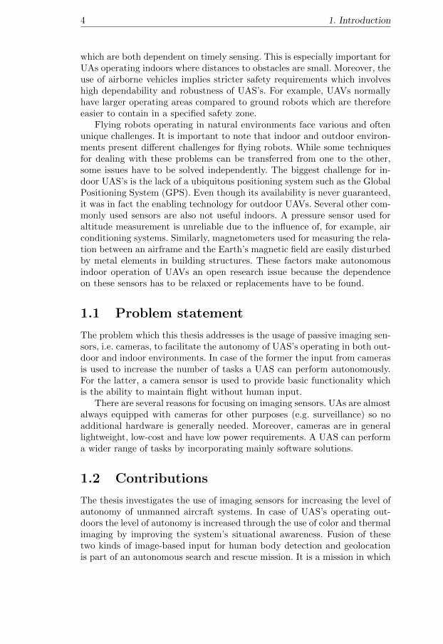
The field of robotics is large and can be categorized in many ways. Mo-bility is one of the ways to categorize robots. Stationary industrial robots(see figure 1.1A) operate in fixed static environments and most often per-form repetitive tasks (e.g. car assembly). Mobile robots, on the other hand,operate in more dynamic domains and require the ability to sense and reactto a changing environment. Issues which need to be addressed in mobilerobotics involve, for example, localization and mapping. The autonomouscar Stanley, developed by the Stanford Racing Team in cooperation withthe Volkswagen Electronics Research Laboratory, is an example of a mobilerobot (see figure 1.1B) [80]. It was able to autonomously navigate for hun-dreds of kilometers during the DARPA Grand Challenge in 2005. This wasachieved by using sensors to localize the vehicle and avoid obstacles on theway.
Another way to categorize robots is by size. In case of airborne platforms,there exist large UAVs, such as the General Atomics MQ-9 Reaper - Predator
2Karel Capek: http://capek.misto.cz/english/presentat.html

3
A
C
B
D
Figure 1.1: A. ABB industrial robots used for car assembly. B. Stanley au-tonomous car. C. Yamaha RMAX unmanned helicopter. D. LinkMAV small-scale unmanned aerial vehicle.
B (4536 kilograms of weight and 20 meters of wing span)3. This thesis, how-ever, focuses on medium and small size UAs. The Autonomous UnmannedAircraft Systems Technologies Lab (UASTechLab, formerly WITAS) RMAXhelicopter [18], presented in figure 1.1C, is an example of a medium size UAV(95 kilograms of weight and length of 3.6 meters). Smaller platforms, alsoreferred to as Micro Air Vehicles (MAVs), which weigh less than 500 gramsand whose largest dimension is smaller than 50 centimeters, are mainly usedfor indoor applications (see figure 1.1D). The smaller the airframe, the nar-rower the range of suitable sensors and computational hardware that can beused. The main restriction is the smaller payload capability which is furtherrestricted by limited on-board power.
Airborne robots face an additional set of issues compared to groundvehicles. The faster dynamics of flying platforms impose strict requirementson timely execution of control tasks as well as on well-timed decision making
3General Atomics Predator B: http://www.ga-asi.com/products/aircraft/
predator_b.php
4 1. Introduction
which are both dependent on timely sensing. This is especially important forUAs operating indoors where distances to obstacles are small. Moreover, theuse of airborne vehicles implies stricter safety requirements which involveshigh dependability and robustness of UAS’s. For example, UAVs normallyhave larger operating areas compared to ground robots which are thereforeeasier to contain in a specified safety zone.
Flying robots operating in natural environments face various and oftenunique challenges. It is important to note that indoor and outdoor environ-ments present different challenges for flying robots. While some techniquesfor dealing with these problems can be transferred from one to the other,some issues have to be solved independently. The biggest challenge for in-door UAS’s is the lack of a ubiquitous positioning system such as the GlobalPositioning System (GPS). Even though its availability is never guaranteed,it was in fact the enabling technology for outdoor UAVs. Several other com-monly used sensors are also not useful indoors. A pressure sensor used foraltitude measurement is unreliable due to the influence of, for example, airconditioning systems. Similarly, magnetometers used for measuring the rela-tion between an airframe and the Earth’s magnetic field are easily disturbedby metal elements in building structures. These factors make autonomousindoor operation of UAVs an open research issue because the dependenceon these sensors has to be relaxed or replacements have to be found.
1.1 Problem statement
The problem which this thesis addresses is the usage of passive imaging sen-sors, i.e. cameras, to facilitate the autonomy of UAS’s operating in both out-door and indoor environments. In case of the former the input from camerasis used to increase the number of tasks a UAS can perform autonomously.For the latter, a camera sensor is used to provide basic functionality whichis the ability to maintain flight without human input.
There are several reasons for focusing on imaging sensors. UAs are almostalways equipped with cameras for other purposes (e.g. surveillance) so noadditional hardware is generally needed. Moreover, cameras are in generallightweight, low-cost and have low power requirements. A UAS can performa wider range of tasks by incorporating mainly software solutions.
1.2 Contributions
The thesis investigates the use of imaging sensors for increasing the level ofautonomy of unmanned aircraft systems. In case of UAS’s operating out-doors the level of autonomy is increased through the use of color and thermalimaging by improving the system’s situational awareness. Fusion of thesetwo kinds of image-based input for human body detection and geolocationis part of an autonomous search and rescue mission. It is a mission in which
1.3 List of publications 5
a user selects a region to be scanned for potential survivors. The result ofthe scanning is a map of victim locations. The generated map can be usedby first responders or a robotic system to, for example, deliver food or med-ical supplies [20, 72]. The car tracking functionality which is also based onthe fusion of color and thermal images provides streams of low level events(i.e. geographical coordinates) of vehicles on the ground. It is then trans-formed into a stream of events that allows for qualitative reasoning aboutthe environment. It allows, for example, for reasoning about vehicles over-taking, entering and leaving crossings. Such a functionality allows for greatlyincreasing the situational awareness of a robotic system [41, 42].
Additionally, two approaches to the UAV indoor localization problemare presented. Both use cameras as the main sensors in the absence of GPS-based positioning. The first approach takes advantage of cooperation with aground robot to provide a UAV with its localization information. The aerialvehicle acts as a remote sensor so that the complete system has a greatersensor range and better reach than any of its components [73]. The secondapproach uses marker-based visual pose estimation where all computationsare done onboard the UAV which increases its autonomy by not relying onexternal computational power [75]. Both approaches have been evaluatedand tested in real flight tests with all components fully functional, withouttethers or other aids.
1.3 List of publications
This thesis is mainly based on the following peer-reviewed publications:
[72] P. Rudol and P. Doherty. Human Body Detection and Geolocaliza-tion for UAV Search and Rescue Missions Using Color and ThermalImagery. Proceedings of the IEEE Aerospace Conference, 2008.
[20] P. Doherty and P. Rudol. A UAV Search and Rescue Scenario withHuman Body Detection and Geolocalization. Proceedings of the 20thAustralian Joint Conference on Artificial Intelligence, 2007.
[42] F. Heintz, P. Rudol, P. Doherty. From Images to Traffic Behavior -A UAV Tracking and Monitoring Application. Proceedings of the 10thInternational Conference on Information Fusion, 2007.
[41] F. Heintz, P. Rudol, P. Doherty. Bridging the Sense-Reasoning GapUsing DyKnow: A Knowledge Processing Middleware Framework. Pro-ceedings of the 30th German Conference on Artificial Intelligence,2007.
[73] P. Rudol, M. Wzorek, P. Doherty. Micro Unmanned Aerial VehicleVisual Servoing for Cooperative Indoor Exploration. Proceedings ofthe IEEE Aerospace Conference, 2008.

6 1. Introduction
[75] P. Rudol, M. Wzorek, P. Doherty. Vision-based Pose Estimation forAutonomous Indoor Navigation of Micro-scale Unmanned AircraftSystems. Proceedings of the IEEE International Conference on Roboticsand Automation, 2010.
The first, third, fifth and sixth publications ([72], [42], [73] and [75],respectively) from the above list are included in the appendix to this thesis.Additionally, the following related publications fall outside the direct scopeof this thesis:
[64] T. Merz, P. Rudol, M. Wzorek. Control System Framework for Au-tonomous Robots Based on Extended State Machines. Proceedings ofthe International Conference on Autonomic and Autonomous Systems,2006.
[90] M. Wzorek, G. Conte, P. Rudol, T. Merz, S. Duranti, and P. Doherty.From Motion Planning to Control - a Navigation Framework for anAutonomous Unmanned Aerial Vehicle. Proceedings of the 21th BristolInternational UAV Systems Conference, 2006.
[23] S. Duranti, G. Conte, D. Lundstrom, P. Rudol, M. Wzorek, and P.Doherty. LinkMAV, a prototype rotary wing micro aerial vehicle. 2007.Proceedings of the 17th IFAC Symposium on Automatic Control inAerospace, 2007.
[13] G. Conte, M. Hempel, P. Rudol, D. Lundstrom, S. Duranti, M. Wzorek,and P. Doherty. High accuracy ground target geo-location using au-tonomous micro aerial vehicle platforms. Proceedings of the AIAAGuidance, Navigation, and Control Conference, 2008.
[74] P. Rudol, M. Wzorek, R. Zalewski, and P. Doherty. Report on senseand avoid techniques and the prototype sensor suite. National Aero-nautics Research Program NFFP04-031, Autonomous flight controland decision making capabilities for Mini-UAVs, 2008.
1.4 Outline
The first part of the thesis deals with the problem of increasing the autonomyof a UAV through improving its situational awareness. Problems of objectdetection, mapping and tracking are addressed. Specifically, human bodydetection and the geolocation problem as well as the issue of vehicle track-ing are addressed in chapter 2. These techniques add functional elementsto outdoor operating UAS’s such as the UASTechLab RMAX autonomoushelicopter.
The problem of localization (determining position and attitude i.e. poseestimation) in indoor environments in the absence of a GPS-based position-ing is addressed in chapter 3. Two approaches which increase the autonomyof UAS’s by allowing for autonomous indoor flight are presented.

1.4 Outline 7
The first one (section 3.4) allows for indoor navigation of a UA in coop-eration with a ground robot. The computationally intensive task of imageprocessing is delegated to a computer on the ground robot which determinesthe UAV’s pose based on a specially designed cube structure attached to theflying vehicle.
In the second approach (section 3.5), a marker-based visual pose esti-mation method is used and all computations are carried out on board theUAV. In both cases, a camera is used to provide both the position of a UAVin flight (replacing the GPS and an altimeter) and attitude angles (mostimportantly heading) replacing a compass.
The thesis concludes and gives directions for future work in chapter 4.

Chapter 2
Fusing thermal and colorimages for objectdetection, tracking andgeolocation
2.1 Introduction and motivation
The use of autonomous unmanned aircraft systems is slowly but steadilybecoming commonplace outside of military application areas. Many of themissions in which UAS’s can be employed include tasks such as ground ob-ject detection, identification, tracking and calculating its geographical loca-tion i.e. geolocation. This chapter presents an algorithm for fusing color andthermal images which is suitable for, for example, detecting and geolocatinghuman bodies as well as for vehicle tracking. Both of these functionalitiescan be used as parts of a UAS mission, effectively increasing the number oftasks which can be carried out without or with minimal human input.
Human body detection and geolocation is an area which is particularlyimportant and beneficial for society in catastrophe or emergency assistancesituations. Rapidly acquiring an awareness of a situation after a man-madeor natural disaster can play an important role in relief efforts. It can supportrescuers by focusing their work where the help is most needed.
The use of autonomous unmanned aircraft to facilitate the help can bevery valuable in such situations since certain types of work can be considereddirty, dull, or dangerous if performed by humans. Specifically, autonomyreduces the involvement of the operator from controlling every movementto supervising the operation. The operator’s load is greatly reduced becausemost of the dull and repetitive work is performed by a robot.
Additionally, performing this task on-board a UAV is beneficial for two
8
2.2 An emergency situation scenario 9
reasons. First, it avoids the need for transmitting the video signal. Onlythe result of the analysis has to be transmitted to an operator. Transmit-ting these results requires less bandwidth which is preferred in catastrophesituations where the necessary infrastructure for transmitting bandwidth-demanding video signal might be unavailable. Second, the situational aware-ness is achieved directly during the flight which would not be the case if thegathered data was gathered for later analysis. Partial information can betransmitted before the complete result is available.
This chapter presents a method for fusing thermal and color video streamsfor creating saliency maps of human bodies as well as vehicle tracking andgeolocation. The saliency maps can be directly used by emergency services.The method can also be an intermediary step in a fully autonomous mis-sion which includes generating a plan of supply (e.g. medicine, food, water)delivery followed by the delivery itself. The vehicle tracking functionality,when used with a road system database, allows for detecting high-level trafficevents. Counting vehicles entering crossing, and detecting reckless overtakesare examples of such events.
The remainder of the chapter is structured as follows. It starts withpresenting an example mission in section 2.2. This is followed by a descrip-tion of the UAS platform used for experimental validation of the proposedtechnique. The existing hardware platform and software architecture arepresented in section 2.3. An overview of the related work in section 2.4 isfollowed by a description of an algorithm for building saliency maps in sec-tion 2.5. Finally, results of using the algorithm are presented in section 2.6followed by a description of how these results can be used in a complete au-tonomous mission in section 2.7. Finally, section 2.8 describes an applicationof the same algorithm in a slightly modified form used for vehicle trackingand geolocation.
2.2 An emergency situation scenario
In order to understand the potential of using UAS’s in emergency situationsit is beneficial to briefly describe an example scenario and outline how arobotic system can be useful in such a setting.
After a natural disaster such as an earthquake or a tsunami wave a largearea has to be searched for potential survivors. This is a prerequisite forplanning the logistics of delivering different kinds of supplies to the survivors.Of course, such a task can be carried out by manned aircraft, but by usinga larger number of smaller autonomous UAVs operating in parallel the taskcan be finished quicker and without risking human pilots’ lives.
A complete mission of this type has to incorporate the following subtasks:
• Scanning an area and searching for salient entities such as injuredhumans, building structures or vehicles.

102. Fusing thermal and color images for object detection, tracking and
geolocation
• Monitoring or surveilling these salient points of interest and continu-ally collecting and communicating information back to ground opera-tors and other platforms to keep them situationally aware of currentconditions.
• Delivering supplies or resources to these salient points of interest ifrequired. For example, identified injured persons should immediatelyreceive a relief package containing food, medical and water supplies.
Although quite an ambitious set of tasks, several of them have alreadybeen achieved to some extent using the existing experimental helicopterplatforms as described in the following subsections.
To be more specific in terms of the scenario, we can assume there aretwo separate parts to the emergency relief scenario in the context sketchedpreviously:
• Part I:
In the first part of the scenario, it is essential that for specific geo-graphic areas, the UAVs cooperatively scan large regions in an attemptto identify injured persons. The result of such a cooperative scan isa saliency map pinpointing potential victims, their geographical co-ordinates but optionally also sensory output such as high resolutionphotos and thermal images. The resulting saliency map can be useddirectly by emergency services or passed on to other UAS’s as a basisfor additional tasks.
• Part II:
In the second part of the scenario, the saliency map generated in Part Ican be used as a basis for generating a logistics plan for several of theUAS’s with the appropriate capabilities to deliver food, water andmedical supplies to the injured. This would also be done in a cooper-ative manner among the platforms.
The remainder of this chapter will focus on Part I of the mission. PartII is briefly described in sections 2.7.1 and 2.7.2 and also in Doherty andRudol [20].
2.3 Experimental platform
This section presents the hardware platform used in the experimental val-idation of the algorithm. The helicopter UAV has been developed duringthe WITAS project ([21]) and is now used in the UASTechLab for outdoorexperimentation [18]. The following subsections present the main aspectsof the UAS hardware as well as the software architecture and the existingsystem components.

2.3 Experimental platform 11
2.3.1 RMAX UAV platform
The UASTechLab platform is a slightly modified Yamaha RMAX helicopter(figure 2.1). It has a total length of 3.6 m (including main rotor) and ispowered by a 21 horsepower two-stroke engine with a maximum takeoffweight of 95 kg. Comparing to a standard RMAX helicopter it has a morepowerful electric generator (200 W) and has a higher landing gear whichallows for placing a camera system underneath the UAV body.
3
Figure 2.1: UASTechLab RMAX autonomous helicopter platform.
The on-board system consists of three PC104 computers. The generalschematic of the system is presented in figure 2.2. The Primary Flight Com-puter (PFC) hosts a Pentium III 700 MHz processor and interfaces with aGPS receiver, a barometric pressure sensor and a magnetic compass. ThePFC also interfaces with the Yamaha RMAX platform through the YamahaAttitude Control System (YACS) (which contains the Yamaha Attitude Sen-sor - YAS) and is the only computer required for maintaining autonomousflight capability when using GPS as a positioning sensor.
The main purpose of the PFC is real-time execution of sensor fusionalgorithms and control modes such as take-off, hovering and 3D path fol-lowing [12].
The Image Processing Computer (IPC) hosts a 700 MHz Pentium IIIprocessor and is responsible for grabbing images from two video camerasand running image processing algorithms (such as the existing vision-basedlanding [63] and vision-based localization [11]). The two cameras (Sony CCD

122. Fusing thermal and color images for object detection, tracking and
geolocation
DRC• 1.4 GHz Pentium M• 1 GB RAM• 512 MB Flash storage
Ethernetswitch
YamahaRMAX
IPC• 700 MHz Pentium III• 256 MB RAM• 512 MB Flash storage
Colorcamera
Thermalcamera
Sensorsuite
Serial
PFC• 700 MHz Pentium III• 256 MB RAM• 512 MB Flash storage
Analog video Ethernet Other
Figure 2.2: Schematic of the computer system and the main hardware com-ponents of the UASTechLab RMAX platform.
block camera FCB-780P1 and a ThermalEye-3600AS2 miniature infraredcamera) are mounted on a pan-tilt unit (PTU-46-17.5W3) and are attachedunder the UA fuselage to a camera platform (see figure 2.3). The platformis vibration isolated by a system of springs.
The video footage from both cameras is additionally recorded at fullframe rate by two miniDV recorders to allow post-flight processing. Theability to record the video in this high fidelity format is very useful forimage processing algorithm development and debugging.
The third on-board system, the Deliberative-Reactive Computer (DRC),hosts a 1.4 GHz Pentium-M and executes all high-level autonomous func-tionalities such as mission and path planning.
All three computers are connected with one-to-one serial lines for real-time communication and with Ethernet links through a switch. The com-munication with the ground station is achieved using a 801.11b/g wirelessEthernet bridge from 3Com.
2.3.2 Software architecture
As the types of missions a UAS can perform become more and more sophisti-cated, a software architecture has to be able to accommodate and coordinatedifferent types of functional modules. The goal when designing and devel-oping the architecture of the UASTechLab system was to enable so called
1Homepage: http://pro.sony.com2Homepage: http://www.l-3com.com3Homepage: http://www.dperception.com

2.3 Experimental platform 13
A B
Figure 2.3: A. Thermal and color cameras (left and right respectively)mounted on a pan-tilt unit underneath the UASTechLab RMAX platform.B. ThermalEye-3600AS thermal camera.
push-button missions, in which the UAS autonomously plans and executestasks from take-off to landing without operator intervention. One such mis-sion is building inspection in which the UAS records video footage of all thefacades of all user selected building structures. The software architecturehas to support many different functional units, such as control modes (take-off, 3D path following, landing), task and path planners, optimal cameraplacement algorithms etc.
The software of the UAS is of a hybrid deliberative/reactive type. It is alayered, hierarchical system with deliberative, reactive and control compo-nents, although the system can easily support both vertical and horizontaldata and control flow. Figure 2.4 presents the functional layer structure ofthe architecture and emphasizes its reactive-concentric nature. The ControlKernel is encapsulated in a Common Object Request Broker Architecture(CORBA) object. Task Procedures (TPs [67]) are high-level procedural exe-cution components which provide a computational mechanism for achievingdifferent robotic behaviors by using both Deliberative Services (DS) andcontrol components in a highly distributed and concurrent manner. De-liberative services provide high-level functionalities such as task and pathplanning and Geographic Information System (GIS) databases.
The Control Kernel is distributed over the three previously mentionedon-board computers as presented in figure 2.5. Execution and coordina-tion of various tasks (from device drivers to continuous control laws) isachieved though the use of event-driven hierarchical concurrent state ma-chines (HCSM; similar to the extended state machines described in [64]). AnHCSM interpreter running in the real-time Linux environment (RTAI Linuxpatch [62]) in each of the machines coordinates the task execution as wellas communication between computers. By using serial lines for communica-

142. Fusing thermal and color images for object detection, tracking and
geolocation
8
Control Kernel
TP
TP
TP
DS
DS
DS
DS - Deliberative ServiceTP - Task Procedure
Functional Layers:ControlReactiveDeliberative
Figure 2.4: Functional structure of the architecture.
tion, the Control Kernel achieves real-time properties despite the physicaldistribution. It is functionally encapsulated into a CORBA object accessibleto TPs (as the Helicopter Server).
The use of a realtime operating system is essential for achieving robustoperation of the Control Kernel. The RTAI Linux patch implements therealtime behavior by executing the code as a Linux kernel module. Theexecution is nonpreemptive and statically scheduled and it has to be peri-odically suspended to allow the non-realtime part of the operating systemto perform its tasks (e.g. keyboard and screen handling, flash memory ac-cess and TCP/IP communication). The three PC104 computers on-boardthe UA have different distribution of processor time between the kernel anduser space parts. On one extreme, PFC is mostly realtime as it performstasks which require strict timing of task execution. On the other extreme,the DRC only uses the realtime execution for timely communication withthe other on-board computers. The IPC is somewhere in between as it han-dles more realtime tasks than the DRC but the execution of tasks is not astime critical as in the case of the PFC.
2.3.3 Existing autonomous functionalities
In order to test the method for fusing thermal and color images, used in thesaliency map building and car tracking algorithms, it has been integratedinto the UASTechLab UAV helicopter system as a new mission functionality.The following existing autonomous functionalities are part of a completemission:

2.4 Related work 15
9
DRC
HCSM interpreter
IPC HCSM interpreter
PFCHCSM interpreter
CORBA Helicopter ServerC Interface
Hardware drivers
KFstate
estimation
Flightcontrol modes
Hardware drivers
PTU control modes
Image processing algorithms
Control Kernel
Task procedures (TPs)
Deliberative services
Figure 2.5: Distributed Control Kernel architecture.
• Take-off: this control mode brings the helicopter platform from theground to a specified altitude.
• Hovering: this is the default control mode of the platform.
• Multiple platform area coverage path planning algorithm: it computespaths for n heterogenous platforms and guarantees complete cameracoverage of the specified area. It takes into account sensor propertiesand platform capabilities when computing the paths.
• 3D path following: this control mode allows for tracking 3D pathsdefined as splines [12].
• Vision-based autonomous landing (without the use of GPS) using aspecially designed landing pattern [63].
2.4 Related work
The task of observing and analyzing human appearance and movement hasbeen of interest to the computer vision community for many years. Theexisting techniques can be categorized in many ways. One of them is the needfor pre-processing, such as background subtraction, which can be achievedby frame differencing [57, 94]. Other factors include the types of features
162. Fusing thermal and color images for object detection, tracking and
geolocation
which are needed for describing human appearance e.g. shape, color andcontours.
A considerable amount of work is based on the idea of detecting humansby parts. For example, a human body can be modeled as an assembly of partswhich are detected separately and represented by co-occurrences of localfeatures [66]. A cascade-of-rejectors with variable size blocks of histogramsof oriented gradients as features can also be used. AdaBoost is used as afeature selection technique to choose appropriate blocks from a large set ofpossible blocks [27]. The use of integral image representation and a rejectioncascade allows for 5 to 30 Hz human detection performance (for images ofsize 320x280 pixels) [95]. Another approach takes advantage of a classifierwhich is a cascade of boosted classifiers working with Haar-like features. Theclassifier is learned using boosting [82]. The details of this technique are arepresented in section 2.5.5.
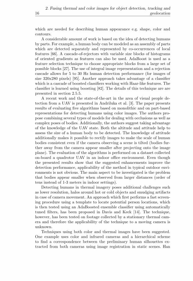
A recent work and the state-of-the-art in the area of visual people de-tection from a UAV is presented in Andriluka et al. [3]. The paper presentsresults of evaluating five algorithms based on monolithic and on part-basedrepresentations for detecting humans using color images. The authors pro-pose combining several types of models for dealing with occlusions as well ascomplex poses of bodies. Additionally, the authors suggest taking advantageof the knowledge of the UAV state. Both the altitude and attitude help toassess the size of a human body to be detected. The knowledge of attitudeadditionally makes it possible to rectify images to make the scale of humanbodies consistent even if the camera observing a scene is tilted (bodies fur-ther away from the camera appear smaller after projecting onto the imageplane). The evaluation of the algorithms is performed on a dataset collectedon-board a quadrotor UAV in an indoor office environment. Even thoughthe presented results show that the suggested enhancements improve thedetection performance, applicability of the method in typical outdoor envi-ronments is not obvious. The main aspect to be investigated is the problemthat bodies appear smaller when observed from larger distances (order oftens instead of 1-3 meters in indoor settings).
Detecting humans in thermal imagery poses additional challenges suchas lower resolution, halos around hot or cold objects and smudging artifactsin case of camera movement. An approach which first performs a fast screen-ing procedure using a template to locate potential person locations, whichis then tested using an AdaBoosted ensemble classifier using automaticallytuned filters, has been proposed in Davis and Keck [14]. The technique,however, has been tested on footage collected by a stationary thermal cam-era and therefore the applicability of the technique to a moving camera isunknown.
Techniques using both color and thermal images have been suggested.One example uses color and infrared cameras and a hierarchical schemeto find a correspondence between the preliminary human silhouettes ex-tracted from both cameras using image registration in static scenes. Han
2.5 A saliency map building algorithm 17
and Bhanu [35] also discuss strategies for probabilistically combining cuesfrom registered color and thermal images. A technique for detecting andtracking moving targets in overlapping electro-optical and infrared sensors(EO/IR) by a probabilistic framework for integrating multiple cues frommultiple sensors also has been proposed [50]. The method has been testedon footage collected by a UAV but its computational requirements are notdiscussed and its usability on-board a UAV is unknown.
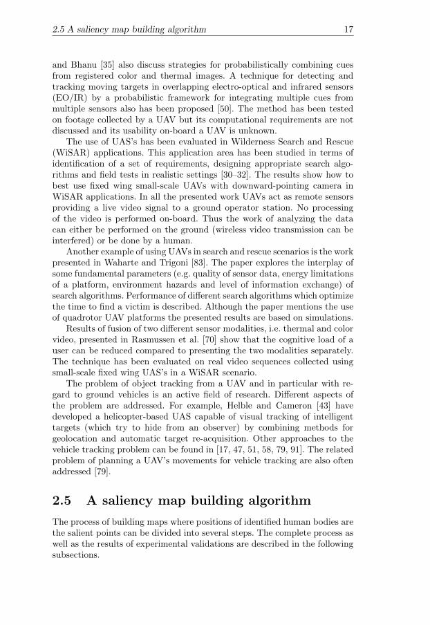
The use of UAS’s has been evaluated in Wilderness Search and Rescue(WiSAR) applications. This application area has been studied in terms ofidentification of a set of requirements, designing appropriate search algo-rithms and field tests in realistic settings [30–32]. The results show how tobest use fixed wing small-scale UAVs with downward-pointing camera inWiSAR applications. In all the presented work UAVs act as remote sensorsproviding a live video signal to a ground operator station. No processingof the video is performed on-board. Thus the work of analyzing the datacan either be performed on the ground (wireless video transmission can beinterfered) or be done by a human.
Another example of using UAVs in search and rescue scenarios is the workpresented in Waharte and Trigoni [83]. The paper explores the interplay ofsome fundamental parameters (e.g. quality of sensor data, energy limitationsof a platform, environment hazards and level of information exchange) ofsearch algorithms. Performance of different search algorithms which optimizethe time to find a victim is described. Although the paper mentions the useof quadrotor UAV platforms the presented results are based on simulations.
Results of fusion of two different sensor modalities, i.e. thermal and colorvideo, presented in Rasmussen et al. [70] show that the cognitive load of auser can be reduced compared to presenting the two modalities separately.The technique has been evaluated on real video sequences collected usingsmall-scale fixed wing UAS’s in a WiSAR scenario.
The problem of object tracking from a UAV and in particular with re-gard to ground vehicles is an active field of research. Different aspects ofthe problem are addressed. For example, Helble and Cameron [43] havedeveloped a helicopter-based UAS capable of visual tracking of intelligenttargets (which try to hide from an observer) by combining methods forgeolocation and automatic target re-acquisition. Other approaches to thevehicle tracking problem can be found in [17, 47, 51, 58, 79, 91]. The relatedproblem of planning a UAV’s movements for vehicle tracking are also oftenaddressed [79].
2.5 A saliency map building algorithm
The process of building maps where positions of identified human bodies arethe salient points can be divided into several steps. The complete process aswell as the results of experimental validations are described in the followingsubsections.
182. Fusing thermal and color images for object detection, tracking and
geolocation
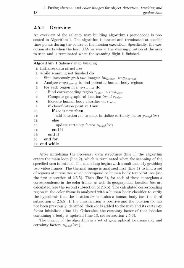
2.5.1 Overview
An overview of the saliency map building algorithm’s pseudocode is pre-sented in Algorithm 1. The algorithm is started and terminated at specifictime points during the course of the mission execution. Specifically, the exe-cution starts when the host UAV arrives at the starting position of the areato scan and is terminated when the scanning flight is finished.
Algorithm 1 Saliency map building
1: Initialize data structures2: while scanning not finished do3: Simultaneously grab two images: imgcolor, imgthermal4: Analyze imgthermal to find potential human body regions5: for each region in imgthermal do6: Find corresponding region rcolor in imgcolor7: Compute geographical location loc of rcolor8: Execute human body classifier on rcolor9: if classification positive then
10: if loc is new then11: add location loc to map, initialize certainty factor pbody(loc)12: else13: update certainty factor pbody(loc)14: end if15: end if16: end for17: end while
After initializing the necessary data structures (line 1) the algorithmenters the main loop (line 2), which is terminated when the scanning of thespecified area is finished. The main loop begins with simultaneously grabbingtwo video frames. The thermal image is analyzed first (line 4) to find a setof regions of intensities which correspond to human body temperatures (seethe first subsection of 2.5.5). Then (line 6), for each of these subregions acorrespondence in the color frame, as well its geographical location loc, arecalculated (see the second subsection of 2.5.5). The calculated correspondingregion in the color frame is analyzed with a human body classifier to verifythe hypothesis that the location loc contains a human body (see the thirdsubsection of 2.5.5). If the classification is positive and the location loc hasnot been previously identified, then loc is added to the map and its certaintyfactor initialized (line 11). Otherwise, the certainty factor of that locationcontaining a body is updated (line 13, see subsection 2.5.6).
The output of the algorithm is a set of geographical locations loci andcertainty factors pbody(loci).

2.5 A saliency map building algorithm 19
2.5.2 Preliminaries
The saliency map building algorithm for the UAS-assisted emergency ser-vices mission has been designed taking into account the following missionrequirements and platform properties.
First, the typical distance between an object of interest and a camera islarge and the algorithm has to be able to cope with objects of small size.Additionally, an object of interest may remain in the camera Field Of View(FOV) only for a short period of time. Even in the case of platforms capableof low velocity flight (such as helicopters) high flight velocity is preferred incase of search and rescue applications because it allows for finding potentialvictims faster. Therefore, the rate of image processing is one of the mostimportant parameters.
α
h
w
FOV
Figure 2.6: Field of view calculation for a downward pointing camera. Theimage plane is schematically depicted with a dashed line.
The optimal altitude for a scanning mission can be computed given thecamera parameters and the requirements of the particular image processingalgorithm. Specifically, the minimal required size of an object in an image,measured in pixels. First, the field of view FOV (see figure 2.6 for illustra-tion) is a function of the altitude h and the view angle α:
FOV = 2 h tan(α
2). (2.1)
Assuming a camera pointing down at a flat ground, the length of theprojection of an object Sw on the image plane Simg can be calculated as:
Simg =Sw w
FOV, (2.2)
where w is the size of the image frame measured in pixels. Both w and αcan be different for vertical and horizontal dimensions of a video frame. Fig-ure 2.7 presents the object projection size for two different frame dimensions

202. Fusing thermal and color images for object detection, tracking and
geolocation
w and two example object sizes resembling a human body (Sw of 1.5 m and1.8 m).
20 30 40 50 60 70 8010
20
30
40
50
60
70
80
height h [m]
S img [p
ixel
s]
w=768, Sw=1.8w=576, Sw=1.8w=768, Sw=1.5w=576, Sw=1.5
Figure 2.7: The size of an object in an image (Simg) depending on the cameraheight (altitude) when FOV is 50 degrees for two different cameras and twodifferent object sizes.
For example, to obtain object projection sizes of at least 20 pixels in theimage for standard PAL resolution4 and a 50 degrees field of view cameralens, the maximum flight altitude is approximately 50 meters. Higher resolu-tion cameras would allow flight at higher altitudes. Flying at lower altitudesmakes the task of image processing easier since a human body appears largerin a video frame. On the other hand, the flight at a lower altitude requiresmore time to complete since the camera covers a smaller area per videoframe.
2.5.3 Image formation
Imaging sensors detect light scattered from viewed scenes and represent theworld as two-dimensional projections. In order to relate a real world objectand its projection in an image plane a perspective model is commonly used.A simple pin-hole camera model (Equation 2.3) expresses the geometricalrelations of a scene and an image where the camera aperture is described asa point and no lenses are used to focus light.
λ
uv1
= A [R|t]
XYZ1
, (2.3)
4PAL resolution: 768×576 for square pixels or 720×576 for non-square pixels

2.5 A saliency map building algorithm 21
where (X,Y, Z) are the coordinates of a point in a three-dimensional sceneand (u, v) are the coordinates of its projection in the image plane. The 3×4matrix [R|t] is the matrix of extrinsic parameters and describes the rotationand translation of the camera in the scene (or vice-versa). Calculating theextrinsic camera parameters R and t is often the task of pose estimationalgorithms. The parameter λ is the homogenous scaling factor. The matrix:
A =
fx 0 cx0 fy cy0 0 1
(2.4)
is composed of the intrinsic parameters and is also referred to as the cameracalibration matrix. It contains focal lengths fx and fy and coordinates ofthe principal point cx and cy. It can also contain a factor which accounts forthe skew due to non-rectangular pixels. In most modern cameras, however,this factor can be neglected.
In practice the pin-hole camera model is insufficient because it does notmodel the effects of distortions introduced by a lens which focuses light on animaging element of a camera. A more comprehensive image formation modelwhich includes radial and tangential lens distortions and is equivalent to 2.3can be rewritten in the following way. For z 6= 0:
xyz
= R
XYZ
+ t (2.5)
x′ = xz ,
y′ = yz
(2.6)
x′′ = x′(1 + k1r2 + k2r
4 + k3r6) + 2p1x
′y′ + p2(r2 + 2x′2)y′′ = y′(1 + k1r
2 + k2r4 + k3r
6) + p1(x2 + 2y′2) + 2p2x′y′,
(2.7)
where r2 = x′2 + y′2, ki and pi are the radial and tangential distortioncoefficients, respectively. Finally, 2.3 becomes:
u = fxx′′ + cx
v = fyy′′ + cy
(2.8)
For efficiency reasons the calculations expressed in Equations 2.7 are oftenimplemented in the form of a lookup table. Such a table maps image coor-dinates distorted by a lens to the ideal ones. The lookup table is initializedwhen the application is started. While using such a table requires allocatinga certain amounts of memory, the speedup can be significant especially onslower hardware.
Calculating the camera matrix P = A[R|t] as well as determining lensdistortion parameters is achieved through a process of camera calibration.Given a number of point correspondences xi ↔ Xi between three-dimensional

222. Fusing thermal and color images for object detection, tracking and
geolocation
points in a scene Xi and two-dimensional points xi in an image the cameramatrix P can be calculated such that xi = PXi for all i. In practice thecamera calibration procedure requires capturing images of a known target(e.g. chessboard-like pattern) of known dimensions to obtain point corre-spondences. Rectangular features are most commonly used in calibrationpatterns because of the ease of determining pixel coordinates of corner fea-tures.
The lens distortion parameters can be calculated together with P orcan be estimated by the requirement that straight lines in scenes have tobe straight in images. The latter method is used with scenes which includestraight line features such as buildings etc. In such a case usage of a calibra-tion pattern is not necessary.
Details of the image formation and camera calibration techniques can befound in Hartley and Zisserman [36].
2.5.4 Thermal camera calibration
Figure 2.8: Schematic view of the procedure used to calibrate the thermalcamera.
While a color camera can be calibrated using the Camera CalibrationToolbox for Matlab [9] the same piece of software cannot be directly usedfor calibrating a thermal camera. The required chessboard-like calibrationpattern is not suitable for use with thermal cameras. The contrast betweenblack and white rectangles which makes it easy to detect corners by visiblelight cameras is not present when viewing the same pattern with a thermalcamera. Additionally, the effects of halos around hot or cold objects typicalfor this kind of camera makes it very difficult to picture sharp corners.
In order to find the focal lengths, principal point and lens distortion pa-rameters, a custom calibration pattern and an add-on to the toolkit havebeen used [86]. To obtain images which look like those taken by a standard
2.5 A saliency map building algorithm 23
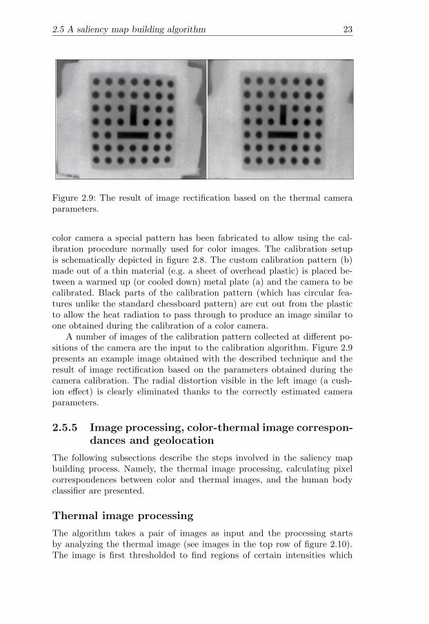
Figure 2.9: The result of image rectification based on the thermal cameraparameters.
color camera a special pattern has been fabricated to allow using the cal-ibration procedure normally used for color images. The calibration setupis schematically depicted in figure 2.8. The custom calibration pattern (b)made out of a thin material (e.g. a sheet of overhead plastic) is placed be-tween a warmed up (or cooled down) metal plate (a) and the camera to becalibrated. Black parts of the calibration pattern (which has circular fea-tures unlike the standard chessboard pattern) are cut out from the plasticto allow the heat radiation to pass through to produce an image similar toone obtained during the calibration of a color camera.
A number of images of the calibration pattern collected at different po-sitions of the camera are the input to the calibration algorithm. Figure 2.9presents an example image obtained with the described technique and theresult of image rectification based on the parameters obtained during thecamera calibration. The radial distortion visible in the left image (a cush-ion effect) is clearly eliminated thanks to the correctly estimated cameraparameters.
2.5.5 Image processing, color-thermal image correspon-dances and geolocation
The following subsections describe the steps involved in the saliency mapbuilding process. Namely, the thermal image processing, calculating pixelcorrespondences between color and thermal images, and the human bodyclassifier are presented.
Thermal image processing
The algorithm takes a pair of images as input and the processing startsby analyzing the thermal image (see images in the top row of figure 2.10).The image is first thresholded to find regions of certain intensities which

242. Fusing thermal and color images for object detection, tracking and
geolocation
correspond to human body temperature. The value of image intensity cor-responding to a certain temperature is usually given by the camera man-ufacturer or can be calibrated by the user. The shapes of the thresholdedregions are analyzed and those which do not resemble a human body (i.e.wrong ratio of minor and major axes of the fitted ellipse and incorrect area)are rejected.
Once human body candidates are found in the thermal image, corre-sponding regions in the color image are calculated.
Figure 2.10: Example input to the image processing algorithm. Thermalimages in the top row and the corresponding color frames in the bottomrow.
Image correspondances and geolocation
Finding corresponding regions using image registration or feature matchingtechniques is infeasible because of mostly different appearance of features incolor and thermal images. For that reason a closed form solution, which takesinto account information about the camera pose in the world is preferred.Computing the corresponding region in the color image starts by calculatingthe coordinates of the target point T (~vT ) whose projection is the pixel inthe thermal image ~ut i.e.
~ut = Pt~vt ~ut ∈ P2 ~vt ∈ P3 (2.9)
where Pt represents extrinsic and intrinsic parameters of the thermal camera.The general scheme of the problem is shown in figure 2.11. A vector lineequation ~g(d) with the direction vector ~vcam which goes through the cameracenter ~vc is:
~g(d) = ~vC + d · ~vcam d ∈ R (2.10)

2.5 A saliency map building algorithm 25
10
World coordinate
system
Camera coordinate
system
X
Y
Z
.
Image plane
X
“lic˙pioru” — 2011/3/7 — 13:28 — page 20 — #30
202. Human body detection and geolocalization by fusing thermal and color
images
16Figure 2.10: Example input to the image processing algorithm. Thermalimages in the top row and the corresponding color frames in the bottomrow.
in color and thermal images. For that reason a closed form solution, whichtakes into account information about the camera pose in the world is pre-ferred.
Computing the corresponding region in the color image starts by calcu-lating the coordinates of the target point T (�vT ) whose projection is thepixel in the thermal image ut i.e.
ut = Ptvt ut ∈ P2 vt ∈ P3 (2.9)
where Pt represents extrinsic and intrinsic parameters of the thermal camera.The general scheme of the problem is shown in figure 2.11. A line equationwith the direction vector vcam which goes through the camera center �vc is:
vT − vC = t · vcam t ∈ R (2.10)
The ground plane is defined by the point G(vG) and the normal vector nwhich is the down component of the NED (North, East, Down) frame:
(vT − vG) · n = 0 (2.11)
Finally, the vector vT which describes the point of intersection of a ray oflight going through the camera center and the pixel of the target can becalculated according to:
vT = vC +(vG − vC) · n
vcam · n· vcam (2.12)
In order to calculate vcam the vector along the X axis of the camera framemust be expressed in the world coordinate frame. This transformation canbe expressed as:
wvcam = PheliPptuPp
�1 0 0
�T(2.13)
“lic˙pioru” — 2011/3/7 — 13:35 — page 20 — #30
202. Human body detection and geolocalization by fusing thermal and color
images
16Figure 2.10: Example input to the image processing algorithm. Thermalimages in the top row and the corresponding color frames in the bottomrow.
in color and thermal images. For that reason a closed form solution, whichtakes into account information about the camera pose in the world is pre-ferred.
Computing the corresponding region in the color image starts by calcu-lating the coordinates of the target point T (�vT ) whose projection is thepixel in the thermal image ut i.e.
ut = Ptvt ut ∈ P2 vt ∈ P3 (2.9)
where Pt represents extrinsic and intrinsic parameters of the thermal camera.The general scheme of the problem is shown in figure 2.11. A line equationwith the direction vector �vcam which goes through the camera center �vc is:
vT = �vC + t · �vcam t ∈ R (2.10)
The ground plane is defined by the point G(vG) and the normal vector nwhich is the down component of the NED (North, East, Down) frame:
(vT − vG) · n = 0 (2.11)
Finally, the vector vT which describes the point of intersection of a ray oflight going through the camera center and the pixel of the target can becalculated according to:
vT = vC +(vG − vC) · n
vcam · n· vcam (2.12)
In order to calculate vcam the vector along the X axis of the camera framemust be expressed in the world coordinate frame. This transformation canbe expressed as:
wvcam = PheliPptuPp
�1 0 0
�T(2.13)
“lic˙pioru” — 2011/3/7 — 13:43 — page 20 — #30
202. Human body detection and geolocalization by fusing thermal and color
images
16Figure 2.10: Example input to the image processing algorithm. Thermalimages in the top row and the corresponding color frames in the bottomrow.
in color and thermal images. For that reason a closed form solution, whichtakes into account information about the camera pose in the world is pre-ferred.
Computing the corresponding region in the color image starts by calcu-lating the coordinates of the target point T (�vT ) whose projection is thepixel in the thermal image �ut i.e.
�ut = Pt�vt �ut ∈ P2 �vt ∈ P3 (2.9)
where Pt represents extrinsic and intrinsic parameters of the thermal camera.The general scheme of the problem is shown in figure 2.11. A vector lineequation �g(d) with the direction vector �vcam which goes through the cameracenter �vc is:
�g(d) = �vC + d · �vcam d ∈ R (2.10)
The ground plane is defined by the point G(vG) and the normal vector nwhich is the down component of the NED (North, East, Down) frame:
(vT − vG) · n = 0 (2.11)
Finally, the vector vT which describes the point of intersection of a ray oflight going through the camera center and the pixel of the target can becalculated according to:
vT = vC +(vG − vC) · n
vcam · n· vcam (2.12)
In order to calculate vcam the vector along the X axis of the camera framemust be expressed in the world coordinate frame. This transformation canbe expressed as:
wvcam = PheliPptuPp
�1 0 0
�T(2.13)
“lic˙pioru” — 2011/3/7 — 13:54 — page 20 — #30
202. Human body detection and geolocalization by fusing thermal and color
images
16Figure 2.10: Example input to the image processing algorithm. Thermalimages in the top row and the corresponding color frames in the bottomrow.
in color and thermal images. For that reason a closed form solution, whichtakes into account information about the camera pose in the world is pre-ferred.
Computing the corresponding region in the color image starts by calcu-lating the coordinates of the target point T (�vT ) whose projection is thepixel in the thermal image �ut i.e.
�ut = Pt�vt �ut ∈ P2 �vt ∈ P3 (2.9)
where Pt represents extrinsic and intrinsic parameters of the thermal camera.The general scheme of the problem is shown in figure 2.11. A vector lineequation �g(d) with the direction vector �vcam which goes through the cameracenter �vc is:
�g(d) = �vC + d · �vcam d ∈ R (2.10)
The ground plane is defined by the point G(�vG) and the normal vector �nwhich is the down component of the NED (North, East, Down) frame:
(�p − �vG) · �n = 0 (2.11)
Finally, the vector �vT which describes the point of intersection of a ray oflight going through the camera center and the target (eq. 2.10) with theground plane (eq. 2.11) can be calculated according to:
�vT = �vC +(�vG − �vC) · �n�vcam · �n · �vcam (2.12)
In order to calculate �vcam the vector along the X axis of the camera framemust be expressed in the world coordinate frame. This transformation canbe expressed as:
�vcam = PheliPptuPp
�1 0 0
�T(2.13)
“lic˙pioru” — 2011/3/7 — 13:38 — page 20 — #30
202. Human body detection and geolocalization by fusing thermal and color
images
16Figure 2.10: Example input to the image processing algorithm. Thermalimages in the top row and the corresponding color frames in the bottomrow.
in color and thermal images. For that reason a closed form solution, whichtakes into account information about the camera pose in the world is pre-ferred.
Computing the corresponding region in the color image starts by calcu-lating the coordinates of the target point T (�vT ) whose projection is thepixel in the thermal image �ut i.e.
ut = Ptvt ut ∈ P2 vt ∈ P3 (2.9)
where Pt represents extrinsic and intrinsic parameters of the thermal camera.The general scheme of the problem is shown in figure 2.11. A line equationwith the direction vector �vcam which goes through the camera center �vc is:
vT = �vC + t · �vcam t ∈ R (2.10)
The ground plane is defined by the point G(vG) and the normal vector nwhich is the down component of the NED (North, East, Down) frame:
(vT − vG) · n = 0 (2.11)
Finally, the vector vT which describes the point of intersection of a ray oflight going through the camera center and the pixel of the target can becalculated according to:
vT = vC +(vG − vC) · n
vcam · n· vcam (2.12)
In order to calculate vcam the vector along the X axis of the camera framemust be expressed in the world coordinate frame. This transformation canbe expressed as:
wvcam = PheliPptuPp
�1 0 0
�T(2.13)
“lic˙pioru” — 2011/3/7 — 13:30 — page 20 — #30
202. Human body detection and geolocalization by fusing thermal and color
images
16Figure 2.10: Example input to the image processing algorithm. Thermalimages in the top row and the corresponding color frames in the bottomrow.
in color and thermal images. For that reason a closed form solution, whichtakes into account information about the camera pose in the world is pre-ferred.
Computing the corresponding region in the color image starts by calcu-lating the coordinates of the target point T (�vT ) whose projection is thepixel in the thermal image ut i.e.
ut = Ptvt ut ∈ P2 vt ∈ P3 (2.9)
where Pt represents extrinsic and intrinsic parameters of the thermal camera.The general scheme of the problem is shown in figure 2.11. A line equationwith the direction vector vcam which goes through the camera center �vc is:
vT − �vC = t · �vcam t ∈ R (2.10)
The ground plane is defined by the point G(vG) and the normal vector nwhich is the down component of the NED (North, East, Down) frame:
(vT − vG) · n = 0 (2.11)
Finally, the vector vT which describes the point of intersection of a ray oflight going through the camera center and the pixel of the target can becalculated according to:
vT = vC +(vG − vC) · n
vcam · n· vcam (2.12)
In order to calculate vcam the vector along the X axis of the camera framemust be expressed in the world coordinate frame. This transformation canbe expressed as:
wvcam = PheliPptuPp
�1 0 0
�T(2.13)
Figure 2.11: Calculating a target’s coordinates.
The ground plane is defined by the point G(~vG) and the normal vector ~nwhich is the down component of the North, East, Down (NED) frame:
(~p− ~vG) · ~n = 0 (2.11)
Finally, the vector ~vT which describes the point of intersection of a ray oflight going through the camera center and the target (eq. 2.10) with theground plane (eq. 2.11) can be calculated according to:
~vT = ~vC +(~vG − ~vC) · ~n~vcam · ~n
· ~vcam (2.12)
In order to calculate ~vcam the vector along the X axis of the camera framemust be expressed in the world coordinate frame. This transformation canbe expressed as:
~vcam = PheliPptuPp(
1 0 0)T
(2.13)
where Pp describes the transformation depending on the undistorted pixelposition ~ut. The matrix Pptu is built to represent the transformation intro-duced by the pan-tilt unit. Pheli represents the attitude of the UAV and isbuilt up from the roll, pitch and yaw angles of the platform.
262. Fusing thermal and color images for object detection, tracking and
geolocation
The method presented can be extended to relax the flat world assumptiongiven the elevation model. The point T can be found by performing ray-tracing along the line described by equation 2.10 to find the intersectionwith the ground elevation map.
The projection in the color image of the world position given by T canbe calculated using the following formula:
~uc = Pc~vT ~uc ∈ P2 ~vT ∈ P3 (2.14)
where Pc constitutes the matrix encoding intrinsic and extrinsic parame-ters of the color camera including the transformation describing the relatingbetween the color and thermal cameras. This transformation can be calcu-lated given a set of known image correspondences uti ↔ u′ci and minimizingthe error between u′ci and uci calculated using equation 2.14 for all i. Thistransformation is constant and is calculated once along with the cameracalibration procedure.
The accuracy of the correspondence calculation is influenced by severalfactors. As can be seen from equation 2.13, all inaccuracies of parametersinvolved in calculating the position and attitude of cameras in the worldcontribute to the overall precision of the solution. The evaluation of the ac-curacy involves investigating the UAV state estimation errors, pan-tilt unitposition accuracy, camera calibration errors etc. In the case of the UASTech-Lab RMAX autonomous helicopter platform, during the experimental val-idation, the corresponding image coordinates were within a subregion oftwenty percent of the video frame size (cf. the marked subregions in colorimages in figure 2.10).
The human body classifier
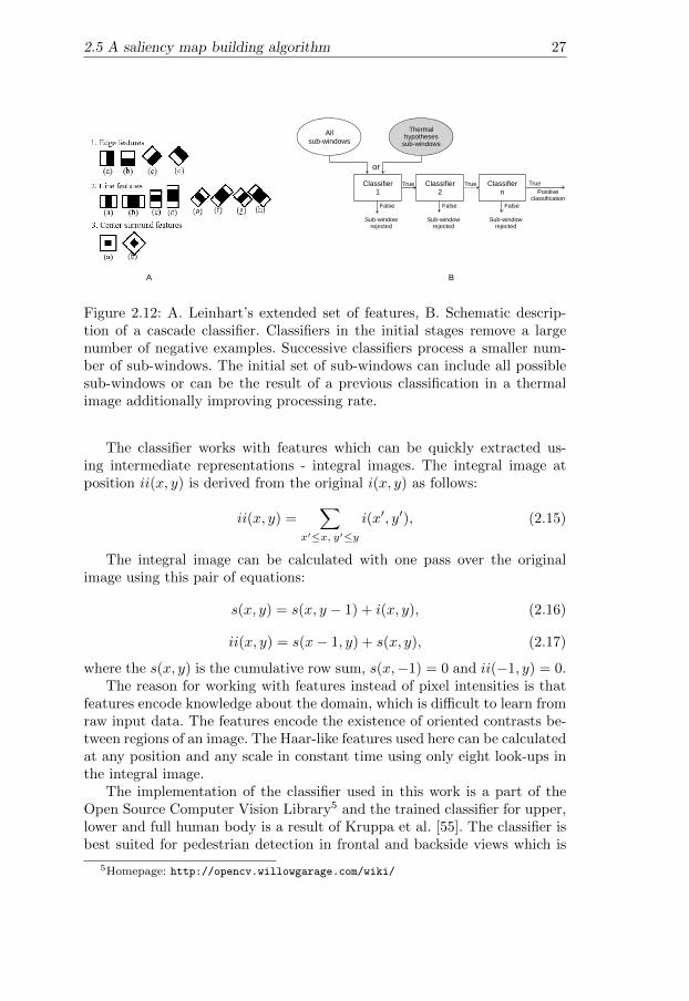
After calculating the coordinates of the pixel in the color image, a region withthe Pc as center (cf. black rectangles in the bottom row images of figure 2.10)is analyzed by an object classifier. The classifier used was first suggestedin Viola and Jones [82]. It uses a cascade of classifiers for object detection.The method also includes a novel image representation, the integral image,for quick detection of features. The method was also extended, for examplein Lienhart and Maydt [59] by extending the original feature set which ispresented in figure 2.12A.
The classifier requires training with positive and negative examples. Dur-ing the learning process the structure of a classifier is built using boosting.The use of a cascade of classifiers allows for dramatic speed up of computa-tions by skipping negative instances and only computing features with highprobability for positive classification. The speed up comes from the fact thatthe classifier, as it slides a window at all scales, works in stages and is ap-plied to a region of interest until at some stage the candidate is rejected orall the stages are passed (see figure 2.12B). This way, the classifier quicklyrejects subregions which most probably do not include features needed forpositive classification (i.e. background processing is quickly terminated).
2.5 A saliency map building algorithm 27
8
A B
Positive classification
TrueClassifier 1
False
Sub-windowrejected
Classifier 2
True
False
Sub-windowrejected
Classifier n
False
Sub-windowrejected
All sub-windows
or
Thermalhypotheses
sub-windows
True
Figure 2.12: A. Leinhart’s extended set of features, B. Schematic descrip-tion of a cascade classifier. Classifiers in the initial stages remove a largenumber of negative examples. Successive classifiers process a smaller num-ber of sub-windows. The initial set of sub-windows can include all possiblesub-windows or can be the result of a previous classification in a thermalimage additionally improving processing rate.
The classifier works with features which can be quickly extracted us-ing intermediate representations - integral images. The integral image atposition ii(x, y) is derived from the original i(x, y) as follows:
ii(x, y) =∑
x′≤x, y′≤yi(x′, y′), (2.15)
The integral image can be calculated with one pass over the originalimage using this pair of equations:
s(x, y) = s(x, y − 1) + i(x, y), (2.16)
ii(x, y) = s(x− 1, y) + s(x, y), (2.17)
where the s(x, y) is the cumulative row sum, s(x,−1) = 0 and ii(−1, y) = 0.The reason for working with features instead of pixel intensities is that
features encode knowledge about the domain, which is difficult to learn fromraw input data. The features encode the existence of oriented contrasts be-tween regions of an image. The Haar-like features used here can be calculatedat any position and any scale in constant time using only eight look-ups inthe integral image.
The implementation of the classifier used in this work is a part of theOpen Source Computer Vision Library5 and the trained classifier for upper,lower and full human body is a result of Kruppa et al. [55]. The classifier isbest suited for pedestrian detection in frontal and backside views which is
5Homepage: http://opencv.willowgarage.com/wiki/
282. Fusing thermal and color images for object detection, tracking and
geolocation
exactly the type of views a UA has when flying above the bodies lying onthe ground.
The classifier parameters have been adjusted to minimize false negativecases. In case of rescue operations it is better to find more false positives thenmissing potential victims. The number of neighboring rectangles needed forsuccessful identification has been set to 1 which makes the classifier acceptvery weak classifications. The factor by which the search window is scaledbetween the subsequent scans has been set to 1.2 meaning that the searchwindow is increased by 20%.
2.5.6 Map building
Since the body classifier is configured to be ”relaxed” it delivers sporadicfalse positive classifications. To deal with most of them the following methodis used to prune the results. Every salient point in the map has two param-eters which are used to calculate the certainty of a location being a humanbody: Tframe which describes the amount of time a certain location was inthe camera view and Tbody which describes the amount of time a certainlocation was classified as a human body. The certainty factor is calculatedas follows:
pbody(loci) =TbodyTframe
(2.18)
A location is considered a body if pbody(loci) is larger than a certain thresh-old (e.g. 0.5 during the flight tests) and Tframe is larger than a desiredminimal observation time. Locations are considered equal if geographicaldistance between them is smaller than a certain threshold (depending onthe geolocation accuracy) and the final value of a geolocated position is anaverage of the observations.
2.6 Experimental validation
The presented technique for geolocation and saliency map building has beenintegrated into the UASTechLab helicopter system and tested in flight tests.The following subsections present an example mission setup and the resultsobtained.
2.6.1 Mission setup
An example complete push button mission setup was as follows:
• The flights were performed at the Swedish Rescue Services AgencyTest Area (figure 2.13A). This is a city-like closed area with road struc-tures, buildings etc. so that the video streams include different typesof textures e.g. grass, asphalt, gravel, water and building rooftops.
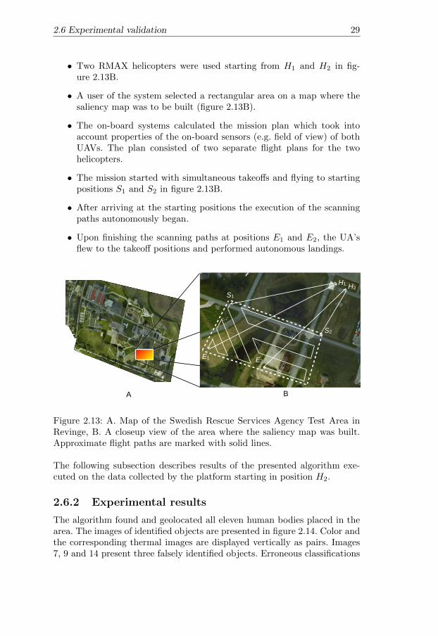
2.6 Experimental validation 29
• Two RMAX helicopters were used starting from H1 and H2 in fig-ure 2.13B.
• A user of the system selected a rectangular area on a map where thesaliency map was to be built (figure 2.13B).
• The on-board systems calculated the mission plan which took intoaccount properties of the on-board sensors (e.g. field of view) of bothUAVs. The plan consisted of two separate flight plans for the twohelicopters.
• The mission started with simultaneous takeoffs and flying to startingpositions S1 and S2 in figure 2.13B.
• After arriving at the starting positions the execution of the scanningpaths autonomously began.
• Upon finishing the scanning paths at positions E1 and E2, the UA’sflew to the takeoff positions and performed autonomous landings.
A B
H1 H2
S2
E2
S1
E1
Figure 2.13: A. Map of the Swedish Rescue Services Agency Test Area inRevinge, B. A closeup view of the area where the saliency map was built.Approximate flight paths are marked with solid lines.
The following subsection describes results of the presented algorithm exe-cuted on the data collected by the platform starting in position H2.
2.6.2 Experimental results
The algorithm found and geolocated all eleven human bodies placed in thearea. The images of identified objects are presented in figure 2.14. Color andthe corresponding thermal images are displayed vertically as pairs. Images7, 9 and 14 present three falsely identified objects. Erroneous classifications

302. Fusing thermal and color images for object detection, tracking and
geolocation
! " # $ % & ' (
) !* !! !" !# !$ !%! " # $ % & ' (
) !* !! !" !# !$ !%
! " # $ % & ' (
) !* !! !" !# !$ !%! " # $ % & ' (
) !* !! !" !# !$ !%
Figure 2.14: Images of classified bodies. Corresponding thermal images areplaced under color images.
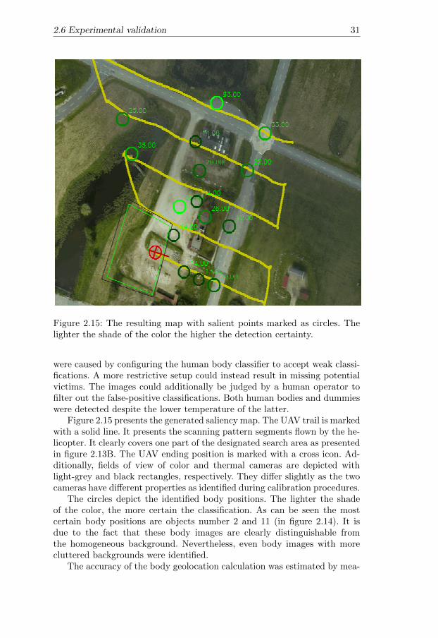
2.6 Experimental validation 31
Figure 2.15: The resulting map with salient points marked as circles. Thelighter the shade of the color the higher the detection certainty.
were caused by configuring the human body classifier to accept weak classi-fications. A more restrictive setup could instead result in missing potentialvictims. The images could additionally be judged by a human operator tofilter out the false-positive classifications. Both human bodies and dummieswere detected despite the lower temperature of the latter.
Figure 2.15 presents the generated saliency map. The UAV trail is markedwith a solid line. It presents the scanning pattern segments flown by the he-licopter. It clearly covers one part of the designated search area as presentedin figure 2.13B. The UAV ending position is marked with a cross icon. Ad-ditionally, fields of view of color and thermal cameras are depicted withlight-grey and black rectangles, respectively. They differ slightly as the twocameras have different properties as identified during calibration procedures.
The circles depict the identified body positions. The lighter the shadeof the color, the more certain the classification. As can be seen the mostcertain body positions are objects number 2 and 11 (in figure 2.14). It isdue to the fact that these body images are clearly distinguishable fromthe homogeneous background. Nevertheless, even body images with morecluttered backgrounds were identified.
The accuracy of the body geolocation calculation was estimated by mea-
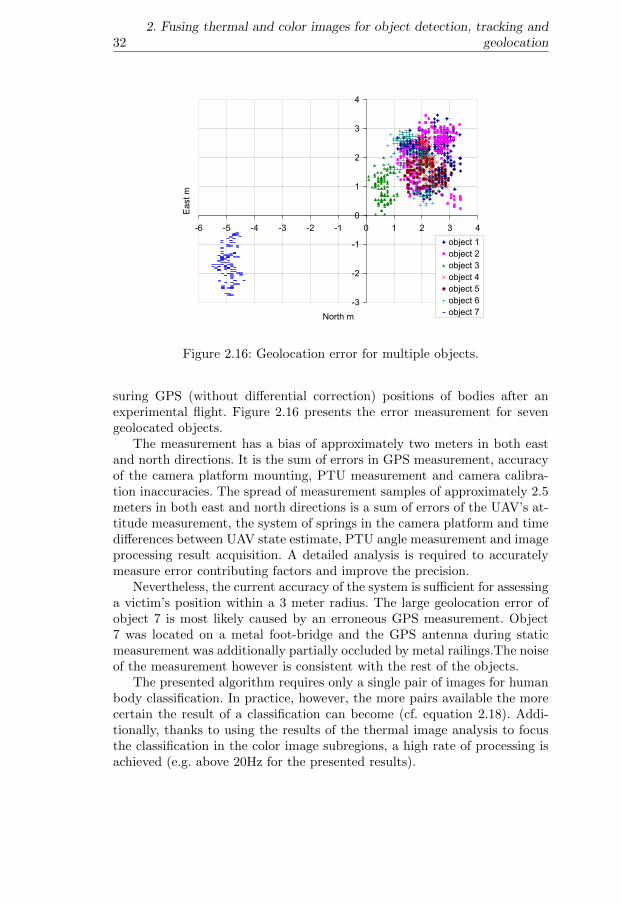
322. Fusing thermal and color images for object detection, tracking and
geolocation
-3
-2
-1
0
1
2
3
4
-6 -5 -4 -3 -2 -1 0 1 2 3 4
North m
East m
object 1
object 2
object 3
object 4
object 5
object 6
object 7
Figure 2.16: Geolocation error for multiple objects.
suring GPS (without differential correction) positions of bodies after anexperimental flight. Figure 2.16 presents the error measurement for sevengeolocated objects.
The measurement has a bias of approximately two meters in both eastand north directions. It is the sum of errors in GPS measurement, accuracyof the camera platform mounting, PTU measurement and camera calibra-tion inaccuracies. The spread of measurement samples of approximately 2.5meters in both east and north directions is a sum of errors of the UAV’s at-titude measurement, the system of springs in the camera platform and timedifferences between UAV state estimate, PTU angle measurement and imageprocessing result acquisition. A detailed analysis is required to accuratelymeasure error contributing factors and improve the precision.
Nevertheless, the current accuracy of the system is sufficient for assessinga victim’s position within a 3 meter radius. The large geolocation error ofobject 7 is most likely caused by an erroneous GPS measurement. Object7 was located on a metal foot-bridge and the GPS antenna during staticmeasurement was additionally partially occluded by metal railings.The noiseof the measurement however is consistent with the rest of the objects.
The presented algorithm requires only a single pair of images for humanbody classification. In practice, however, the more pairs available the morecertain the result of a classification can become (cf. equation 2.18). Addi-tionally, thanks to using the results of the thermal image analysis to focusthe classification in the color image subregions, a high rate of processing isachieved (e.g. above 20Hz for the presented results).

2.7 Complete mission 33
2.7 Complete mission
The following subsections briefly present how the generated saliency map canbe integrated into a complete autonomous mission. For the full descriptionsee Doherty and Rudol [20].
2.7.1 Package delivery
After successful completion of Part I of the scenario, a saliency map withgeolocated positions of the injured people has been generated. In the nextphase of the mission, the goal is to deliver medical, food and water suppliesto the injured. In order to achieve this part of the mission, one would requirea task planner to plan for logistics, a motion planner to plan the paths forone or more UAVs to supply and delivery points and an execution monitorto monitor the execution of highly complex plan operators. Each of thesefunctionalities would also have to be tightly integrated in the system. Thesecomponents are described in subsection 2.7.2.
This part of the mission is developed primarily in simulation with hardware-in-the-loop. The on-board computer system which includes a simulator ofthe UAV dynamics executes all functionalities necessary for completing themission on the actual flight tests hardware. Additionally, a physical proto-type of a mechanism for carrying and releasing packages has been developedand tested. Figure 2.17 presents two images of the prototype system.
Figure 2.17: Two frames of video presenting the prototype mechanism forcarrying and releasing packages using an electromagnet. An arrow points toa package being carried. The top left picture presents the on-board cameraview.
For these logistics missions, the use of one or more UAVs with diverseroles and capabilities is assumed. Additionally, n injured body locations,

342. Fusing thermal and color images for object detection, tracking and
geolocation
several supply depots and several supply carrier depots are assumed to begiven (see figure 2.18). A UAV Search and Rescue Scenario 11
Fig. 8. A Supply Depot (left) and a Carrier Depot (right)
!"#$%&'()*+,
-./
012(+33#$45
012(+33#$45
5*#*)5'6'$*5
5*#*)5'6'$*5
(+33#$45'7)'$('
8+,3)"#'6'$*5
8+,3)"#5#44
5*#*)5'6'$*59!
,)$
5*#*':+";(;'5
9.2:"#$$',<=>$+? 1+33#$4%&'()*+,
%&'()*+,9!
5*#*':+";(;'5
8"#@5'&'()*'
:"#$,'7)'5*
%&'()*;+$A+$;*+,
5*#*'
5*#*)5
:"#$
5*#*'5
Fig. 9. System Architecture Overview
conditions to be monitored during execution of the plan by an execution moni-tor in order to relax the assumption that no failures can occur. Such conditionsare expressed as temporal logical formulas and evaluated on-line using formulaprogression techniques. This execution monitor notifies the plan executor whenactions do not achieve their desired results and one can then move into a planrepair phase.
The plan executor translates operators in the high-level plan returned byTALplanner into lower level command sequences which are given to the commandexecutor. The command executor is responsible for controlling the UAV, eitherby directly calling the functionality exposed by its lowest level Flight Command
Figure 2.18: A supply depot (left) and a carrier depot (right).
2.7.2 Planning, execution and monitoring
Figure 2.19 shows part of the UAV architecture, with an emphasis on thosecomponents that are the most relevant for planning, execution and executionmonitoring.
At the top of the center column is the plan executor which given a mis-sion request, calls DyKnow [39, 40], a knowledge processing middleware, toacquire essential information about the current contextual state of the worldor the UAV’s own internal states. Together with a domain specification anda goal specification related to the logistics scenario, this information is fed toTALplanner [19], a logic-based task planner which outputs a plan that willachieve the designated goals, under the assumption that all actions succeedand no failures occur. Such a plan can also be automatically annotated withglobal and/or operator-specific conditions to be monitored during executionof the plan by an execution monitor in order to relax the assumption that nofailures can occur. Such conditions are expressed as temporal logical formulasand evaluated on-line using formula progression techniques. This executionmonitor notifies the plan executor when actions do not achieve their desiredresults and one can then move into a plan repair phase. The plan execu-tor translates operators in the high-level plan returned by TALplanner intolower level command sequences which are given to the command executor.The command executor is responsible for controlling the UAV, either by di-rectly calling the functionality exposed by its lowest level Flight CommandLanguage (FCL) interface or by using task procedures (TPs) through the TPExecutor subsystem. The TP Executor is part of the Modular Task Architec-ture (MTA) [22], which is a reactive system designed in the procedure-basedparadigm and developed for loosely coupled heterogeneous systems. A task

2.7 Complete mission 35
Fig. 8. A Supply Depot (left) and a Carrier Depot (right)
!"#$%&'()*+,
-./
012(+33#$45
012(+33#$45
5*#*)5'6'$*5
5*#*)5'6'$*5
(+33#$45'7)'$('
8+,3)"#'6'$*5
8+,3)"#5#44
5*#*)5'6'$*59!
,)$
5*#*':+";(;'5
9.2:"#$$',<=>$+? 1+33#$4%&'()*+,
%&'()*+,9!
5*#*':+";(;'5
8"#@5'&'()*'
:"#$,'7)'5*
%&'()*;+$A+$;*+,
5*#*'
5*#*)5
:"#$
5*#*'5
Fig. 9. System Architecture Overview
conditions to be monitored during execution of the plan by an execution moni-tor in order to relax the assumption that no failures can occur. Such conditionsare expressed as temporal logical formulas and evaluated on-line using formulaprogression techniques. This execution monitor notifies the plan executor whenactions do not achieve their desired results and one can then move into a planrepair phase.
The plan executor translates operators in the high-level plan returned byTALplanner into lower level command sequences which are given to the commandexecutor. The command executor is responsible for controlling the UAV, eitherby directly calling the functionality exposed by its lowest level Flight Command
Figure 2.19: System Architecture Overview
is a behavior intended to achieve a goal in a limited set of circumstances. Atask procedure is the computational mechanism that achieves this behavior.The TPs have the ability to use deliberative services, such as the task plan-ner described above or motion planners [89, 90], in a reactive or contingentmanner and to use traditional control services in a reactive or contingentmanner and thereby integrate deliberation and reaction.
During plan execution, the command executor adds formulas to be mon-itored to the execution monitor. DyKnow continuously sends informationabout the development of the world in terms of state sequences to the moni-tor, which uses a progression algorithm to partially evaluate monitor formu-las. If a violation is detected, this is immediately signaled as an event to thecommand executor, which can suspend the execution of the current plan,invoke an emergency brake command, optionally execute an initial recoveryaction and finally signal new status to the plan executor. The plan executoris then responsible for completing the recovery procedure.
The fully integrated system is implemented on the UAVs and can be usedon-board for different configurations of the logistics mission described inPart II of the larger mission. The simulated environments used are in urbanareas and quite complex. Plans are generated in the millisecond to secondsrange using TALplanner and empirical testing shows that this approach

362. Fusing thermal and color images for object detection, tracking and
geolocation
is promising in terms of integrating high-level deliberative capability withlower-level reactive and control functionality.
2.8 A vehicle tracking and geolocation appli-cation
Autonomous vehicle tracking and geolocation can play a major role in ap-plications such as traffic behavior analysis which can contribute to increas-ing road safety. Instead of a human operator trying to maintain situationalawareness about a traffic condition in an area, a UAS equipped with ap-propriate sensors and algorithms can be used. One approach is for a UASto relay video streams and other data to an operator for human inspection.Another, more scalable approach, is for a UAS to monitor the traffic situa-tions which arise and only report back the high level events observed, suchas cars turning in intersections or performing overtakes.
The process of going from images to detection of high-level events canbe divided into two parts. First, an image processing algorithm detects andtracks an object in raw video, geolocates the tracked object and producesa stream of world positions. Second, an algorithm which performs tempo-ral and spacial analysis of the data and detects certain types of behaviors(e.g. entering crossings and overtakes) and maintains situational awareness.
This section describes how the method developed in the previous section(specifically the first and second subsections of 2.5.5) can be used to imple-ment the first part of the task. The second part of the task is described insection 2.8.2.
2.8.1 Image processing
The task of image processing is to calculate world coordinates of vehiclestracked in video sequences. First, an object tracker is used to find pixel co-ordinates of the vehicle of interest based on color and thermal input images.Second, the geographical location of the object is calculated and expressed asworld coordinates. The object tracker developed for the purpose of this workcan be initialized automatically or manually. The automatic mode choosesthe warmest object on a road segment (description of the road system isfetched from a GIS database) within the thermal camera view and withina certain distance from the UAV (cf. the process of calculating the distanceto a tracked object described in section 2.5.5). The area around the initialpoint is checked for homogeneity in thermal and color images. The objectis used to initialize the tracker if its area is consistent with the size of acar signature. This method of initialization works with satisfactory resultsfor distances up to around 50m from the tracked object. If the tracker isinitialized incorrectly the user can choose an object of interest manually byclicking on a frame of the color or thermal video. The corresponding pixel

2.8 A vehicle tracking and geolocation application 37
position (for color and thermal images) is calculated based on the parame-ters of the cameras, the UAV’s position and attitude and the model of theground elevation.
After initialization, the tracking of an object is performed independentlyin the color and thermal video streams. Tracking in the thermal image isachieved by finding the extreme value (warmest or coldest spots) withina small (5 percent of the image size) window around the previous result.Object tracking in color video sequences is also performed within such asmall window and is done by finding the center of mass of a color blob in theHSI (Hue, Saturation, Intensity) color space. The thresholding parametersare continuously updated to compensate for illumination changes. Trackingin both images is performed at full frame rate (i.e. 25Hz) which allows forcompensating for moderate illumination changes and moderate speeds ofrelative motion between the UAV and the tracked object. If either of thetrackers does not find a similar blob in two consecutive frames, the trackingis considered to be lost. The problem of automatic reinitialization as well asmore sophisticated interplay between both trackers, is not addressed in thiswork.
Finding pixel correspondences between the two cameras is difficult toachieved by feature matching commonly used in stereo-vision algorithmssince objects generally appear different in color and infrared images. Be-cause of this, the distance to an object whose projection lies in a given pixelmust be determined. Given the camera parameters, helicopter pose and theground elevation model the distance to an object can be calculated (see thesecond subsection of 2.5.5). It is the distance from the camera center to theintersection between the ground model and the ray going through the pixelbelonging to the object of interest. For the environment in which the flighttests were performed the error introduced by the flat world assumption (i.e.ground elevation model simplified to a plane) is negligible. Finally, calcu-lating pixel correspondences between the two cameras can be achieved byperforming pixel geolocation using the intrinsic and extrinsic parameters ofone of the cameras followed by applying a inverse procedure (i.e. projectionof geographical location) using the other camera’s parameters.
Using the described object tracker, several data series of world coordi-nates of tracked vehicles were generated. Two kinds of video sequences wereused as data sources. In the first kind (figure 2.20A) the UAV is stationaryat altitudes of 50 or 60 meters and observes two vehicles as they drive ona nearby road. In the other kind (figure 2.20B) both the car and the UAVare moving. The ground vehicle drives several hundreds meters on the roadsystem passing through two crossings and the UAV follows the car at alti-tudes from 25 to 50 meters. For sequences containing two cars, the trackerwas executed twice to track both vehicles independently.
A precise measure of the error of the computed world location of thetracked object is not known because the true location of the cars was notrecorded during the flight tests. The accuracy of the computation is influ-
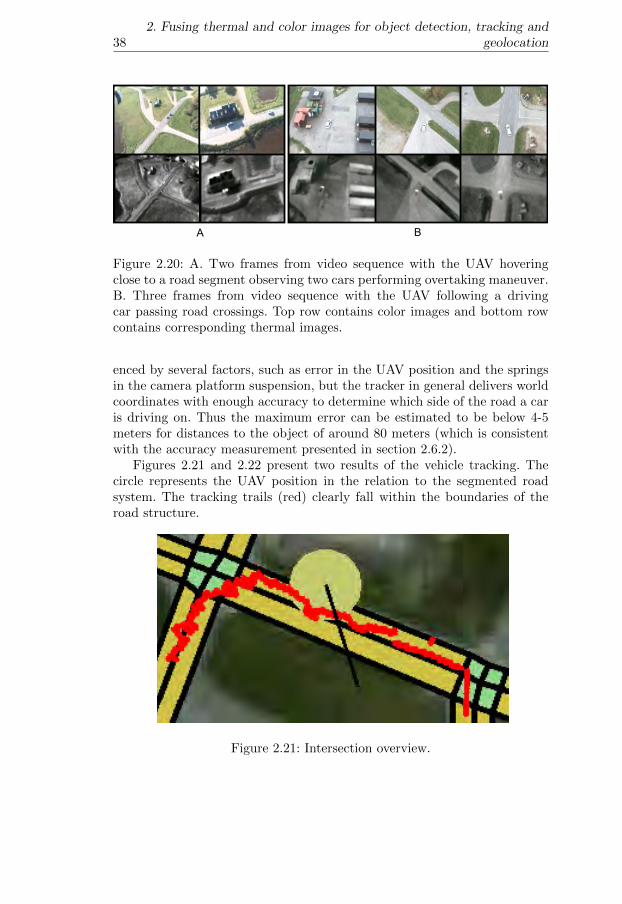
382. Fusing thermal and color images for object detection, tracking and
geolocation
A B
Figure 2.20: A. Two frames from video sequence with the UAV hoveringclose to a road segment observing two cars performing overtaking maneuver.B. Three frames from video sequence with the UAV following a drivingcar passing road crossings. Top row contains color images and bottom rowcontains corresponding thermal images.
enced by several factors, such as error in the UAV position and the springsin the camera platform suspension, but the tracker in general delivers worldcoordinates with enough accuracy to determine which side of the road a caris driving on. Thus the maximum error can be estimated to be below 4-5meters for distances to the object of around 80 meters (which is consistentwith the accuracy measurement presented in section 2.6.2).
Figures 2.21 and 2.22 present two results of the vehicle tracking. Thecircle represents the UAV position in the relation to the segmented roadsystem. The tracking trails (red) clearly fall within the boundaries of theroad structure.
Figure 2.21: Intersection overview.

2.8 A vehicle tracking and geolocation application 39
Figure 2.22: Overtake overview.
2.8.2 High level traffic situation awareness
To achieve complex missions an autonomous UAV operating in dynamicenvironments must create and maintain situational awareness. This can beachieved by continually gathering information from many sources, selectingthe relevant information for the current task, and deriving models aboutthe environment and the UAV itself. Often models close to the sensor data,suitable for traditional control, are not sufficient for deliberation. The needfor more abstract models creates a sense-reasoning gap. This section brieflypresents how DyKnow, a knowledge processing middleware ([39, 40]), canbridge the gap in a concrete UAV traffic monitoring application. Streamsof UAV positions generated as described in previous section are used toconstruct and maintain qualitative object structures modeling the parts ofthe environment necessary to recognize the traffic behavior of the trackedvehicles in real-time.
In a traffic monitoring scenario a human operator tries to maintain sit-uational awareness about a traffic situation in an urban area using UAVslooking for accidents, reckless driving, or other relevant activities. One ap-proach to this scenario would be for one or more UAVs to relay videos andother data to the operator for human inspection. Another, more scalable ap-proach, would be for the UAVs to monitor the traffic situations which ariseand only report back the high level events observed, such as cars turning inintersections and doing overtakes, to reduce the amount of information andhelp the operator focus her attention. This section describes such a traf-fic monitoring application where cars are tracked by a UAV platform andstreams of observations are fused with a model of the road system in orderto draw conclusions about the behavior of the cars in the environment. Theinput consists of images taken by the color and thermal cameras on the UAVwhich are fused and geolocated to a single world position. This stream ofpositions is then correlated with a geographical information system in order
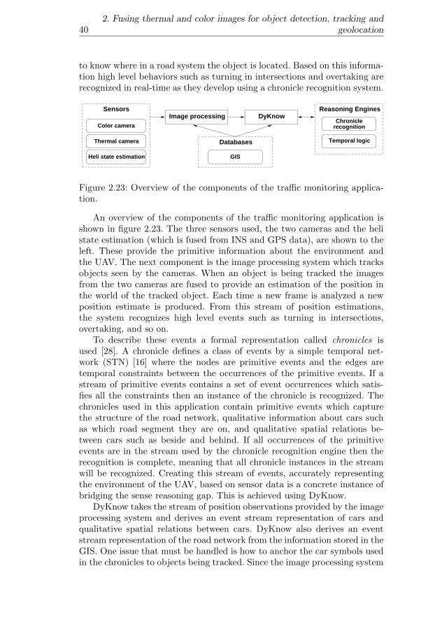
402. Fusing thermal and color images for object detection, tracking and
geolocation
to know where in a road system the object is located. Based on this informa-tion high level behaviors such as turning in intersections and overtaking arerecognized in real-time as they develop using a chronicle recognition system.
Color camera
Thermal camera
Heli state estimation
Chroniclerecognition
Temporal logic
Reasoning Engines
GIS
Databases
Image processing DyKnowSensors
Fig. 1. Overview of the components of the traffic monitoring application.
An overview of the components of the traffic monitoring application is shown inFig. 1. The three sensors used, the two cameras and the heli state estimation (whichis fused from INS and GPS data), are shown to the left. These provide the primitiveinformation about the environment and the UAV. The next component is the imageprocessing system which tracks objects seen by the cameras. When an object is beingtracked the images from the two cameras are fused to provide an estimation of theposition in the world of the tracked object. Each time a new frame is analysed a newposition estimate is produced. From this stream of position estimations, the systemrecognizes high level events such as turning in intersections, overtaking, and so on.
To describe these events a formal representation called chronicles is used [1]. Achronicle defines a class of events by a simple temporal network (STN) [2] where thenodes are primitive events and the edges are temporal constraints between the occur-rences of the primitive events. If a stream of primitive events contains a set of eventoccurrences which satisfies all the constraints then an instance of the chronicle is rec-ognized. The chronicles used in this application contain primitive events which capturethe structure of the road network, qualitative information about cars such as which roadsegment they are on, and qualitative spatial relations between cars such as beside andbehind. If all occurrences of the primitive events are in the stream used by the chron-icle recognition engine then the recognition is complete, meaning that all chronicleinstances in the stream will be recognized. Creating this stream of events, accuratelyrepresenting the environment of the UAV, based on sensor data is a concrete instance ofbridging the sense reasoning gap. This is done by a knowledge processing middlewarecalled DyKnow (see Section 5) [3, 4].
DyKnow takes the stream of position observations provided by the image process-ing system (see Section 4) and derives an event stream representation of cars and qual-itative spatial relations between cars (see Section 7.1). DyKnow also derives an eventstream representation of the road network from the information stored in the GIS. Oneissue that must be handled is how to anchor the car symbols used in the chronicles toobjects being tracked. Since the image processing system may lose track of cars or starttracking other objects than cars DyKnow has to dynamically estimate and continuallymonitor the type and identity of objects being tracked. To do this, the normative behav-ior of different objects and the conditions for assuming that two objects have the sameidentity are described using temporal logic (see Section 6). When a tracked object isfound which satisfies the normative behavior for e.g. a car a new car representation iscreated and the tracked object is linked to the new car representation. From this moment
Figure 2.23: Overview of the components of the traffic monitoring applica-tion.
An overview of the components of the traffic monitoring application isshown in figure 2.23. The three sensors used, the two cameras and the helistate estimation (which is fused from INS and GPS data), are shown to theleft. These provide the primitive information about the environment andthe UAV. The next component is the image processing system which tracksobjects seen by the cameras. When an object is being tracked the imagesfrom the two cameras are fused to provide an estimation of the position inthe world of the tracked object. Each time a new frame is analyzed a newposition estimate is produced. From this stream of position estimations,the system recognizes high level events such as turning in intersections,overtaking, and so on.
To describe these events a formal representation called chronicles isused [28]. A chronicle defines a class of events by a simple temporal net-work (STN) [16] where the nodes are primitive events and the edges aretemporal constraints between the occurrences of the primitive events. If astream of primitive events contains a set of event occurrences which satis-fies all the constraints then an instance of the chronicle is recognized. Thechronicles used in this application contain primitive events which capturethe structure of the road network, qualitative information about cars suchas which road segment they are on, and qualitative spatial relations be-tween cars such as beside and behind. If all occurrences of the primitiveevents are in the stream used by the chronicle recognition engine then therecognition is complete, meaning that all chronicle instances in the streamwill be recognized. Creating this stream of events, accurately representingthe environment of the UAV, based on sensor data is a concrete instance ofbridging the sense reasoning gap. This is achieved using DyKnow.
DyKnow takes the stream of position observations provided by the imageprocessing system and derives an event stream representation of cars andqualitative spatial relations between cars. DyKnow also derives an eventstream representation of the road network from the information stored in theGIS. One issue that must be handled is how to anchor the car symbols usedin the chronicles to objects being tracked. Since the image processing system
2.9 Conclusion 41
may lose track of cars or start tracking other objects than cars DyKnow hasto dynamically estimate and continually monitor the type and identity ofobjects being tracked. To do this, the normative behavior of different objectsand the conditions for assuming that two objects have the same identityare described using temporal logic. When a tracked object is found whichsatisfies the normative behavior for e.g. a car a new car representation iscreated and the tracked object is linked to the new car representation. Fromthis moment the car representation will be updated each time the trackedobject is updated. Since links only represent hypotheses, they are alwayssubject to becoming invalid given additional observations, and thereforethe UAV continually has to verify the validity of the links. This is doneby monitoring that the normative behavior of the assumed object type isnot violated. For example, an object assumed to be a car must not violatethe normative constraints on cars, e.g. leaving the road. If it does violatethe corresponding link is removed, in other words the object is no longerassumed to be a car. To evaluate temporal logical formulas DyKnow has toderive temporal models representing the value of the variables used in theformulas. Since these models are derived from the sensor data it is anotherconcrete example of how DyKnow can be used to bridge the sense reasoninggap.
Further details are provided in Heintz et al. [41, 42].
2.9 Conclusion
This chapter presented a method for fusing thermal and color video streamsfor the purpose of increasing the level of autonomy through improving situ-ational awareness for unmanned aircraft systems. Two methods have beendescribed which rely on color and thermal video streams as the main sourceof information. The first method deals with the problem of building saliencymaps where human body locations are marked as points of interest. Suchmaps can be used in emergency situations to help first responders to quicklyfocus the help effort in places where it is most needed. The task of acquir-ing the first overview of the situation can be delegated to autonomouslyoperating UAS’s.
The second presented functionality deals with the problem of trackingand geolocation of vehicles. The obtained streams of vehicle positions canbe used by a reasoning system to analyze traffic behaviors such as recklessovertakes, speeding and entering crossings. Thanks to an automatic analysisof the traffic situation, the load of an operator can be greatly reduced andthe situational awareness improved.

Chapter 3
Towards autonomousindoor navigation ofsmall-scale UAVs
3.1 Introduction and motivation
Enabling autonomous indoor flight and navigation allows a wide range oftasks to be carried out by UAS’s with minimal or without operator involve-ment. A concrete example where the use of indoor flying UAVs would bebeneficial is the recent earthquake and the resulting tsunami in Japan. Be-cause of the great devastation caused by the tsunami wave and the radiationcaused by a reactor malfunction, the immediate surroundings of the reactorbecame very dangerous for humans. In such a situation the use of UAS’sfrom a safe distance would help to protect the well-being of the rescuers byallowing them to explore and inspect the inside of the reactor building be-fore eventually sending in humans. This is a typical example of a dangeroustask where the use of robots helps saving or protecting human lives.
The progress in the field of autonomous unmanned aircraft has allowedfor the use of UAS’s in many applications in military, academic and com-mercial domains. Thanks to advances in several fields, the range of missionsthat unmanned aerial vehicles can perform today is substantial. The evo-lution of sensor technologies, state estimation techniques, mission and pathplanning methods, software frameworks, to name a few, made this progresspossible. The number UAS’s operating outdoors and the kinds of tasks beingperformed show a high level of maturity.
Autonomous indoor flight and navigation, on the other hand, are still intheir infancy. Even though steady progress is being made, the range of tasksperformed autonomously by indoor UAS’s is small compared to their out-door counterparts. There are several reasons for this. Compared to outdoor
42

3.1 Introduction and motivation 43
operating UAS’s, the solutions to the indoor flight and navigation problemshave to deal with the following issues:
• Lack of a ubiquitous positioning system. Even though the GPS is notalways reliable it was in fact the enabling technology for outdoor au-tonomous navigation. Indoors, however, the GPS cannot be used atall.
• Limited payload of small airframes suitable for indoor use limits thetypes and the number of appropriate sensors. Certain types of sensorsare not available at all in small scale (e.g. radar) and a platform canoften only carry a single sensor of a certain kind.
• Lower sensor accuracy and/or range due to miniaturization. For ex-ample, inertial navigation systems based on Micro Electro MechanicalSystems (MEMS) sensors drift much faster than systems based onlarger Ring Laser Gyroscopes (RLG) used in full size aircraft such asthe Airbus A320; miniature cameras often have very simple lightweightplastic lenses instead of professional glass lenses which influences theimage quality. Additionally, sensors such as Laser Range Finders (LRFs)have shorter measurement ranges. Even though distances to obstaclesin indoor environment are normally smaller compared to outdoor en-vironments, this factor cannot be neglected.
• Limited computational power and lack of dedicated hardware com-ponents such as Floating Point Units (FPUs) impose restrictions onalgorithms. Many of the existing algorithms are inadequate for smallplatforms because the computational requirements prevent them fromdelivering timely results.
• Restricted power due to limited payload available for the power source.The battery power which is used both for propulsion and avionics sys-tems has to be used efficiently to maximize the flight time. Achievingautonomous flight only for a very short time span is not desirablebecause it limits the types of missions a UAS can perform.
• Properties of the indoor environment introduce several challenges. First,an indoor environment imposes strict requirements on timely and ac-curate state estimation in relation to obstacles. While in outdoor envi-ronments there exists, in the general case, a possibility to ”escape” toa safer location (e.g. by increasing the altitude to fly above obstacles)this option is normally not available indoors.
Additionally, the field of view of sensors has a more ”local” character.Outdoors it is often possible to get a bird’s eye view of the environ-ment. Such a view from the top often allows for identifying landmarksto aid the localization task especially in case of the so-called kidnappedlocalization problem (i.e. when there is no initial knowledge about the

44 3. Towards autonomous indoor navigation of small-scale UAVs
robot location). In such a case a more global view allows for quickerlocation determination. One solution to this problem for indoor UAVsis the use of wide field of view camera lenses, but this makes the effec-tive resolution of the cameras smaller which negatively influences theaccuracy of the sensor data. Another solution could be using a cameraon a tilting unit but such a device adds mechanical complexity, weightand consumes electrical power.
All of these issues need to be taken into consideration and addressed toallow indoor UAVs to perform the same wide range of missions as outdoorUA’s perform today.
The key problem which needs to be addressed is localization. This meansestimating at least three translational and three rotational Degrees of Free-dom (DOF) of a vehicle in its environment. This process is also referredto as state or pose estimation. In the case of UAS missions performed inunknown environments, the localization has to be performed along withmapping. This is achieved by means of Simultaneous Localization and Map-ping (SLAM) techniques. However, due to the above listed issues, mainlythe lower sensor accuracy and lower computational power, both efficient androbust solutions are required. In case of larger airframes, with larger payloadcapabilities, the available computational power can compensate for sensorinaccuracies or redundant sensor configurations can be used.
The timing requirements of the indoor state estimation solutions dependon the inherent aerodynamical stability of the type of UAV airframes used.Airships or dirigibles, having slow dynamics, allow for longer periods of timewhen the state is not estimated. This kind of airframe is the most inherentlystable and has the least tendency to drift around and possibly collide withobstacles in the environment. Rotor-based platforms in different configura-tions (e.g. tail-, coaxial-, quad-) require more timely state estimations inorder to navigate safely. For this kind of airframe it is especially importantto design efficient algorithms which allow control inputs to be computedevery few milliseconds.
Like the timing aspect, the accuracy of the state estimation is also veryimportant since distances to obstacles in indoor environments are normallysmall. The accuracy of the sensors that can be used on a small scale airframeis relatively low and therefore requires optimal usage of available informationthrough sensor fusion techniques, which in turn have to be computationallyefficient to be executed on the on-board hardware.
Even though it seems like many solutions could be transferred from thewell developed field of indoor navigation of ground robots, indoor localiza-tion of UAVs suffers from the major drawback of lacking a direct measure oftravelled distance (i.e. odometry). Even though odometers based on wheelencoders are not perfect, obtaining odometry information of equal fidelityon an airborne vehicle is a much more complex task. Instead of reading in-formation delivered by simple wheel encoders, solutions utilizing integrationof the Inertial Measurement Units (IMU) or optic flow are required for UAs.

3.1 Introduction and motivation 45
This makes the adaptation and use of many techniques developed for groundrobots challenging.
This chapter presents two approaches that enable indoor flight and nav-igation of small-scale UAS’s. The first one is based on cooperating with aground robot to facilitate the indoor localization of a UAV. The role of theground robot in this setting is to provide the UAV with location information.This kind of cooperation allows for taking advantage of the well developedtechniques for ground robot localization together with the ability of a flyingrobot to position its sensors in a way normally not available to a groundrobotic system. For example, as can be observed in figure 3.1, the UAV canprovide a view of what is behind an obstacle. Such a view would not beaccessible to the ground robot on its own.
Figure 3.1: The indoor navigation though cooperation. The collaborativesystem has a greater sensor range and better reach than any of its compo-nents.
The second approach is computationally contained on-board a UAV andtakes advantage of fusing a vision-based state estimate with inertial datato provide localization information. The method utilizes a marker-basedcamera pose estimation, often used in augmented reality applications toreplace the information normally provided by a GPS and a compass sensor.Thanks to the possibility of using many markers, the indoor flight can be
46 3. Towards autonomous indoor navigation of small-scale UAVs
performed in a larger area and the solution can be considered a low-costindoor localization system which can rapidly enable indoor flight.
Outline
The remainder of this chapter is structured as follows. First, the differentplatforms and hardware used during validation of the proposed indoor nav-igation techniques are presented in section 3.2, followed by a description ofthe related work in section 3.3. The method for cooperative indoor explo-ration performed by a UAV and a ground robot is presented in section 3.4.Finally, a description of the method for marker-based visual state estimationis presented in section 3.5.
3.2 Experimental platforms
Several hardware platforms and components were used in the process ofdeveloping and validating the two indoor UAV navigation solutions. Thissection describes the micro air vehicles, wheeled ground robots and com-puter systems used for the validation. First, the platforms involved in thevalidation of the collaborative navigation (i.e. the LinkMAV and two groundrobots) are presented. Second, the hardware elements involved in the marker-based visual navigation approach are described including a high accuracyreference system used for validating the accuracy of the method.
3.2.1 Cooperative navigation
Figure 3.8 presents the schematic view of the system used for experimentalvalidation of the system. The main components of the system are presentedin the remainder of this section.
LinkMAV
The LinkMAV, presented in figure 3.3B, is an in-house developed, double-rotor coaxial helicopter platform. This kind of configuration does not requirea tail rotor commonly used in standard helicopter designs. The two rotordisks counter each others’ torques and the heading control is achieved bydifferentiating the rotational velocity of the rotors. The LinkMAV weighsaround 500 grams without payload, its largest dimension is approximately500 millimeters and it can stay in the air for around 20 minutes [23].
In 2005 and 2007 the platform took part in the US-European Micro AirVehicle Competition (MAV051 and MAV072) winning the best rotorcraftaward and scoring the third place in the indoor competition, respectively.
1MAV05: http://aeromav.free.fr/MAV05/aeromav/aero-mav-garmisch-de.htm2MAV07: http://www.recherche.enac.fr/MAV07

3.2 Experimental platforms 47
Onboard MAV System Ground Robot System
Ground Station System
2.4GHz Video Transmitter
2.4GHz Video Transmitter
Robot Computer
Thermal Camera
CCDCamera
2.4GHz Video Receiver
2.4GHz Video Receiver
Flight ControlBoard
2.4GHzWirelessModem
R/CReceiver
CCDCamera
Pan-TiltUnit
GroundControl Station
Computer
868MHzWirelessModem
868MHzWirelessModem
Serial to PPM
Converter
RS232 Analog Video FirewireConnections:
Or
PWM signals PPM signal
WirelessEthernet
Access Point
WirelessEthernetInterface
Ethernet
Backup Pilot System
2.4GHzWirelessModem
Figure 3.2: The cooperative exploration experimental system componentsand interconnections between them.
The LinkMAV is equipped with two lightweight cameras: a thermal cam-era and a color CCD. The thermal camera is a Thermal-Eye 3600AS from L-3Communications3 which delivers a PAL resolution analogue video stream.The CCD camera is a miniature high resolution Panasonic KX141 fromBlack Widow A/V4. Both video signals are sent to the ground station using2.4GHz transmitters and receivers from Black Widow A/V for the groundoperator view or on-ground image processing purposes.
Micropilot flight control board
During the experiments, the LinkMAV used a MicroPilot 2028g flight controlboard5 for attitude stabilization. All control inputs (i.e. roll, pitch, yaw andthrust) to the MicroPilot board are in the form of Pulse Width Modulation(PWM) signals provided by the onboard R/C receiver.
3Homepage: http://www.l-3com.com4Homepage: http://www.blackwidowav.com5Homepage: http://www.micropilot.com

48 3. Towards autonomous indoor navigation of small-scale UAVs
9
BA
Figure 3.3: A. The Pioneer 3 AT ground robot, B. The LinkMAV.
Ground robots
Two ground vehicles were used for experimentation: a Pioneer 3 AT outdoorrobot from MobileRobots Inc.6, presented in figure 3.3A and a Zerg plat-form developed at the Freiburg University [54]. A 1.6GHz Pentium Mobilelaptop was used to control both robots including the pan-tilt unit (Direct-edPerception 46-17.5W7) and to host image processing algorithms. A SonyDCR-HC90E8 video camera was connected to the laptop through a Firewireinterface.
Ground station system
The Ground Station (GS) subsystem receives both thermal and color CCDanalog video signals which can be used by the GS computer for image pro-cessing purposes or ground operator view. The Graphical User Interface(GUI) provides means for controlling the ground robot and the LinkMAVthrough a wireless Ethernet connection.
3.2.2 Marker-based visual indoor navigation
Two quadrotor UAV platforms were used for the validation of the marker-based positioning system. The Hummingbird-based system as well as theLinkQuad platform are presented in the following subsections.
Hummingbird UAV platform.
The Hummingbird quadrotor UAV (see Figure 3.4A) from Ascending Tech-nologies GmbH [34] has been used as one of the test platforms. The Hum-mingbird can carry up to 200 grams of payload and has 20 minutes of
6Homepage: http://www.activrobots.com7Homepage: http://www.dperception.com8Homepage: http://pro.sony.com

3.2 Experimental platforms 49
BA
Figure 3.4: The Hummingbird quadrotor UAV with the LinkBoard I flightcontrol board, B. The LinkQuad quadrotor UAV platform.
endurance. Its diameter is approximately 50 cm and the total weight isaround 500 grams. The platform’s own electronics (X-Base and ResearchPi-lot boards) implements the inner control loop (attitude stabilization) run-ning at 1 kHz. The UAV can be flown by a human pilot via an RC transmitterbut it also accepts control signals (i.e. roll, pitch and yaw angles and thrustcommands) via an RS232 connection.
The LinkBoard (revision I) from UAS Technologies Sweden AB9 hasbeen used as the flight control computer. Thanks to the board’s modulardesign it is capable of performing a wide range of tasks. In this application,the 520 MHz XScale processor running Windows CE 6.0 operating systemhosts the vision-based pose estimation algorithm. A Logitech Quickcam Pro5000 provides a video stream via a USB connection. The result of the poseestimation is delivered via an RS232 link to a second processor (60 MHzARM7) which implements the sensor fusion algorithm. A second processor ofthe same type implements four proportional-integral-derivative (PID) loopscommanding all the control channels of the UAS.
The flight control board interfaces with the ground control station soft-ware using a 2.4 GHz wireless modem from AeroComm10. The ground sta-tion software is used to monitor the on-board software execution by display-ing the telemetry data. The modem can also be used to send commands tothe UAS. For example, the hovering position, altitude, or heading can bechanged during an autonomous flight.
All the additional components, i.e. the LinkBoard flight control board,the camera, the modem and a 330 mAh battery, have a total weight ofapproximately 50 grams.
9Homepage: http://www.uastech.com10Homepage: http://www.aerocomm.com

50 3. Towards autonomous indoor navigation of small-scale UAVs
LinkQuad UAV platform.
The LinkQuad quadrotor UAV (see Figure 3.4B) from UAS TechnologiesSweden AB11 has been used for the validation of the marker-based position-ing system.
The LinkQuad’s airframe is characterized by a modular design whichallows for easy reconfiguration to adopt to a variety of applications. Thanksto a compact design (below 70 centimeters tip-to-tip) the platform is suit-able for both indoor and outdoor use. It is equipped with custom designedoptimized carbon fiber propellers which contribute to an endurance of ap-proximately 30 minutes. Depending on the required flight time, one or two2.6 Ah batteries can be placed inside an easily swappable battery module.The maximum take-off weight of the LinkQuad is 1.4 kilograms with up to300 grams of payload.
The platform is equipped with the LinkBoard III flight control system.The LinkBoard has a modular design and this allows for adjusting the re-quired computational power depending on mission requirements. In the ba-sic configuration the LinkBoard is equipped with two Cortex-M3 microcon-trollers (72 MHz) but can be extended with two Gumstix Overo modules (upto 720 MHz). The integrated sensors include a 3-axis accelerometer (±2/±6g range), 3 rate gyroscopes, an absolute pressure sensor, a differential pres-sure sensor and a 4-channel 12-bit 1 MSPS analog to digital converter. TheLinkQuad communicates with the ground station using a 2.4 GHz (115200bits per second data rate) wireless modem from AeroComm. Additionally,the communication can be achieved using wireless Ethernet (802.11b/g) in-tegrated with the Gumstix boards.
The LinkBoard supports external sensors which can be interfaced withusing RS232 or USB connections. In the configuration used here a 0.3 megapixelFireFly MV monochrome USB camera from Point Grey12 was used. It is ca-pable of delivering images of up to 640× 480 at a rate of up to 60 Hz. Thecamera is mounted on a pan-tilt module attached to the LinkQuad.
The main components of the system used during the validation of themarker-based positioning system are presented in figure 3.5. The high accu-racy reference data (position, velocity and orientation) obtained using thepositioning system described in the following section is sent to the groundstation software (LinkGS) and is immediately forwarded to the on-boardsystem using the wireless modem. The marker-based positioning algorithmreceives inertial data from the Sensor Microcontroller Unit (Sensor MCU)and uses images delivered by the camera to compute the same set of pa-rameters of the UAV in the environment. The results of the algorithm arethen sent to the Control MCU where this data, as well as the reference in-formation are logged at the rate of 500 Hz on a Secure Digital (SD) memorycard.
11Homepage: http://www.uastech.com12Point Grey: http://www.ptgrey.com

3.2 Experimental platforms 51
Sensor MCU
(Inertial data)
Control MCU
(Logging)
GumstixImage processing & Filtering
USBConnections: PWM SPI Ethernet
2.4GHzWirelessModem
LinkBoard III
LinkQuad
2.4GHzWirelessModem
Ground Station System
LinkGS
Reference System
Vicon Tracker
RS232
Figure 3.5: The main system components used for validation of the marker-based positioning system.
3.2.3 Indoor positioning reference system
The UASTechLab uses a commercial indoor motion capture system from Vi-con13 both as the source of indoor positioning information for autonomousflight and as a high accuracy reference system for validating other indoorpositioning solutions. The system consists of ten T10 cameras. Each cam-era has the resolution of 1 megapixel and captures 10-bit greyscale images(maximum 1120 × 896 pixels) up to 2000 times per second. In the full res-olution, however, the rate is limited to 250 frames per second. The systemis installed in a 9.5 × 6 × 2.45 meters room and the camera placement aswell as the coordinate system axes used are depicted in figure 3.6. The T10cameras illuminate the scene with infrared light which is reflected by a setof markers attached to a tracked physical object. The configuration of thereflective markers defines an object and its position and orientation is com-puted in real-time. The cameras are connected to the Vicon MX Giganetswitch which is also responsible for time synchronization of the system. Theswitch connects to a PC running the software for data collection and anal-ysis. From there the motion tracking data can be logged and also retrievedin real-time to be used for, for example, autonomous flight of a UAV.
The accuracy of UASTechLab indoor positioning system for objects inmotion is difficult to estimate as it would require an additional reference sys-tem to compare it to. To assess the static accuracy a set of measurementswas performed. Figure 3.7 shows plots of the measured positions in X and Y
13Vicon: http://www.vicon.com

52 3. Towards autonomous indoor navigation of small-scale UAVs
X
Y
Z
Figure 3.6: The UASTechLab indoor positioning system camera setup.
directions (Z has very similar characteristics as the X direction) and rotationaround the X axis (Y and Z rotations have very similar characteristics) of astationary object placed in the center of the coordinate system. The objecthad a set of reflective markers placed in a rectangular pattern with a sidedimension of 25 cm. Table 3.1 presents maximum values and standard devi-ations of position and orientation of the same object for all dimensions. Themaximum error of position is 0.228 mm and the maximum orientation angleerror is 0.0267 degrees in this particular experiment. Even though the X andZ positions exhibit a larger error and apparent oscillations (see figure 3.7Position X) the static error is minuscule. This makes the system a very highaccuracy reference system for evaluating other positioning solutions.
3.3 Related work
Research with small-scale unmanned aircraft systems is being pursued inseveral different fields. Development of various kinds of airframes is anexample of an active research area [6, 23, 34, 71]. Theoretical and prac-
Table 3.1: Position and rotation maximum error and standard deviations fora static measurement.
Maximum (abs) Standard deviation
X 0.2280 0.1253Position [mm] Y 0.0849 0.0235
Z 0.2036 0.1148X 0.0215 0.0087
Rotation [degree] Y 0.0249 0.0059Z 0.0267 0.0070

3.3 Related work 53
1 1.5 2 2.5 3 3.5 4 4.5 5
−0.2−0.1
00.10.2
Position X
[s]
[mm
]
1 1.5 2 2.5 3 3.5 4 4.5 5
−0.05
0
0.05
[s]
[mm
]
Position Y
1 1.5 2 2.5 3 3.5 4 4.5 5−0.02
−0.01
0
0.01
0.02Rotation X
[s]
[deg
ree]
Figure 3.7: Position in X and Y directions and rotation around the X axisof a static object placed in the center of the coordinate system measuredusing the UASTechLab reference positioning system.
tical solutions to various control problems are also studied by many re-searchers [7, 25, 44, 69, 85]. Many of the solutions address particular typesof control problems, for example aggressive maneuvering and aerobatics withsmall UAVs [29, 49, 61, 65, 68]. Work on particular problems where UAVsare used for experimentation is also often reported. For example, Hoffmannet al. [45] describes an information-theoretic distributed control architec-ture based on particle filters to facilitate search by a mobile sensor network.In this work, four quadrotor UAVs are used to search for a rescue beacon.Other types of work with small-scale UAS’s involve path planning [37], targettracking [38], mapping [52] and obstacle avoidance [8]. From the perspectiveof this chapter, however, the most relevant work can be found in the field ofindoor localization.
Several approaches to the indoor navigation problem take advantage of

54 3. Towards autonomous indoor navigation of small-scale UAVs
the Vicon MX camera system14, usually used for motion capturing applica-tions. It incorporates a set of cameras which also illuminate the environmentwith highly efficient and powerful infrared LED light. The system deliv-ers a 6 Degrees of Freedom (6-DOF) solution using lightweight reflectiveballs attached to a vehicle’s structure. A six camera configuration of theVicon system allows, for example, for simultaneous tracking of four quadro-tor MAVs and multiple ground vehicles in a 5 × 5 × 2 meter flight volumein Schweighofer and Pinz [77]. A disadvantage of this technique is the staticnature of the environment setup where motion capturing or pose estimationtakes place. Once cameras are set up they remain stationary. Explorationof an unknown environment cannot be performed using this method, thusrestricting possible applications. Other examples of using motion capturingsystems for enabling indoor flight are presented in How et al. [48] and Saadet al. [76].
Other approaches to indoor MAV navigation include using artificial mark-ers commonly used in augmented reality applications [4], or fusing visioninformation (obtained from light diodes attached to a MAV) and inertialdata for a real-time attitude estimation of a quadrotor platform [24]. Alter-native solutions take advantage of an artificial beacon on a blimp MAV [15]or use custom low power FPGA (Field-Programmable Gate Arrays) boardsfor vision aided attitude stabilization for a quadrotor MAV [26].
A number of solutions take advantage of different types of artificial fea-tures to enable pose estimation for MAVs. One of them employs two cameras,one mounted on a pan-tilt unit on the ground and one on-board a quadrotorMAV [2]. The two cameras track colored blobs attached both to the UASand to the ground camera. Besides the need for off-board processing, thedisadvantage of this solution is a rather limited flight envelope accessibleto a MAV. This method allows for indoor flight, but preferably above theground camera. This considerably limits the operational range of the MAV.A different method makes use of information obtained from a target whichtakes advantage of a moire pattern [81]. The pose of a camera is calculatedrelative to a novel pattern which requires backlighting. The flight test resultspresented show the applicability of the method for controlling a quadrotorplatform by calculating the position and the yaw angle of the UAS. Thedisadvantage of this system is a limited operational range because it is noteasy to obtain multiple unique instances for this kind of marker. Anotherapproach based on using artificial markers and fusion with the inertial datacan be found in Zhang et al. [92].
Several attempts have been made to solve the indoor navigation problemby means of SLAM. For example, a monocular vision SLAM technique forUAS’s has been proposed in [10]. It exploits the architectural features ofmanmade indoor environments, namely corners detectable in corridors. Thecontribution of this work is ”a new absolute range and bearing measurementalgorithm using monocular camera”. Unfortunately the authors do not pro-
14Webpage: http://www.vicon.com/products/viconmx.html
3.3 Related work 55
vide enough detail to judge the applicability of the method for on-boardexecution nor any results that use the technique in closed-loop experiments.Recently, a vision-based approach, where the vehicle is localized using adownward looking monocular camera has been proposed by Blosch et al.[5]. A visual SLAM algorithm tracks the pose of the camera, while, simul-taneously, building an incremental map of the surrounding region allowingfor autonomous indoor flight.
A single camera solution is a basis for a navigation system in Soumelidiset al. [78].The system is capable of 3D localization but it requires an apriori map of the environment. The proposed algorithm is computationallyintensive and is executed off-board on a wirelessly transmitted video stream.Similarly, Wendel et al. [84] propose a novel algorithm for monocular visuallocalization for MAVs based on the concept of virtual views in 3D space. Thesystem takes advantage of a precomputed map and under the assumptionthat significant parts of the scene do not alter their geometry they serve asnatural landmarks.
A number of solutions suggest incorporating biologically inspired meth-ods in order to deal with limited computational capabilities of small-scaleUAS’s. Utilization of optic flow techniques has received the widest atten-tion. It can be shown that optic flow can constrain the error in velocity andattitude [53]. The technique, however, does not completely eliminate thepositional drift and additional information (such as geo-referenced images)is required for an accurate position estimation as described in [11]. Otherbiologically inspired approaches can be found in Zhang et al. [93] and Zingget al. [96]
Recently, systems based on ranging sensors have gained a considerableamount of attention. A system based on a laser range finder which uses aparticle filter to globally localize a quadrotor platform in a pre-computedmap has been suggested [33]. The need for off-board computation, however,makes the system vulnerable to communication interruptions. Another ap-proach taking advantage of a laser range finder as well as stereo-vision canbe found in Achtelik et al. [1]. Unfortunately, commercially available small-scale laser range finders are much heavier than miniature video cameras.From a platform’s endurance perspective imaging sensors are much moreattractive for UAV navigation.
Recently, work based on gaming console’s hardware has been reported.Wenzel et al. [87] proposed taking advantage of this kind of low-cost andlight-weight commodity consumer hardware. The Nintendo Wii remote in-frared (IR) camera is used for obtaining a relative pose between a UAV anda ground robot. The system is capable of taking-off, following and landingon a pad attached to a UGV [87, 88]. Similarly, Lange et al. [56] suggestusing a RGB-D sensor (Microsoft Kinect gaming control sensor) for UAVindoor navigation. Thanks to the low-cost of such sensors it is foreseeablethat more approaches based on this kind of hardware will be proposed inthe future.

56 3. Towards autonomous indoor navigation of small-scale UAVs
3.4 UAV navigation through cooperation witha ground vehicle
This section describes a solution to the UAV indoor navigation problembased on cooperation between a ground robot and a UAV. The remainderof this section is structured as follows. It starts with a general descriptionof the system in section 3.4.1. Section 3.4.2 presents the image processingand the pose estimation technique used as well as the details of the customLED pattern design. The accuracy evaluation results are presented in sec-tion 3.4.3. It is followed by a description of the control system of the UAVin section 3.4.4. The experimental setup and the results of the flight testsare presented in section 3.4.5.
3.4.1 System overview
The system consists of two main elements as presented in figure 3.8 . Namely,a UAV and a ground robot. The backup pilot’s system is only required toenhance the safety of operation and is used to relay control commands fromthe ground system to the UAV.
Servos, Speed
Controllers
Flight Control Board
R/C Receiver
UAV system
Image Processing
Control
Ground Robot System
Serial to PWM
Converter
868MHzWireless Modem
Backup Pilot System
868MHzWireless Modem
2.4GHzWireless Modem
R/C Transmitter
2.4GHzWireless Modem
Figure 3.8: Main functional components of the system.
A video camera which is connected to a computer performing the image
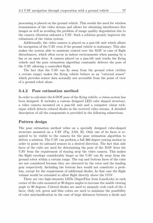
3.4 UAV navigation through cooperation with a ground vehicle 57
processing is placed on the ground vehicle. This avoids the need for wirelesstransmission of the video stream and allows for obtaining interference freeimages as well as avoiding the problem of image quality degradation due tothe camera vibration onboard a UAV. Such a solution greatly improves therobustness of the vision system.
Additionally, the video camera is placed on a pan-tilt unit which allowsfor navigation of the UAV even if the ground vehicle is stationary. This alsomakes the system able to maintain control over the MAV in case of flightdisturbances, which often occur in indoor environments when passing by afan or an open door. A camera placed on a pan-tilt unit tracks the flyingvehicle and the pose estimation algorithm constantly delivers the pose ofthe UAV allowing a controlled flight.
The fact that the UAV can fly away from the ground robot (withina certain range) makes the flying vehicle behave as an ”external sensor”which provides sensor data normally not accessible from the point of viewof a ground robot alone.
3.4.2 Pose estimation method
In order to calculate the 6-DOF pose of the flying vehicle, a vision system hasbeen designed. It includes a custom designed LED cube shaped structure,a video camera mounted on a pan-tilt unit and a computer vision tech-nique which detects colored diodes in the received video stream. A detaileddescription of all the components is provided in the following subsections.
Pattern design
The pose estimation method relies on a specially designed cube-shapedstructure mounted on a UAV (Fig. 3.9A, B). Only one of its faces is re-quired to be visible to the camera for the pose estimation algorithm todeliver a solution. The UAV can perform a full 360 degree yawing motion inorder to point its onboard sensors in a desired direction. The fact that sidefaces of the cube are used for determining the pose of the MAV frees theUAV from the requirement of staying atop the video camera. This makesthe flight envelope considerably larger as the UAV can fly away from theground robot within a certain range. The top and bottom faces of the cubeare not considered because they are obscured by the rotor and the landinggear respectively. Including the bottom face would not constitute a prob-lem, except for the requirement of additional diodes. In that case the flightvolume would be extended to allow flight directly above the UGV.
There are two high-intensity LEDs (SuperFlux from LumiLeds) in eachcorner of the cube mounted at 90 degree angles to increase the usable viewingangle to 90 degrees. Colored diodes are used to uniquely code each of the 4faces. Only red, green and blue colors are used to minimize the possibilityof color misclassification in the case of large distances between a diode and
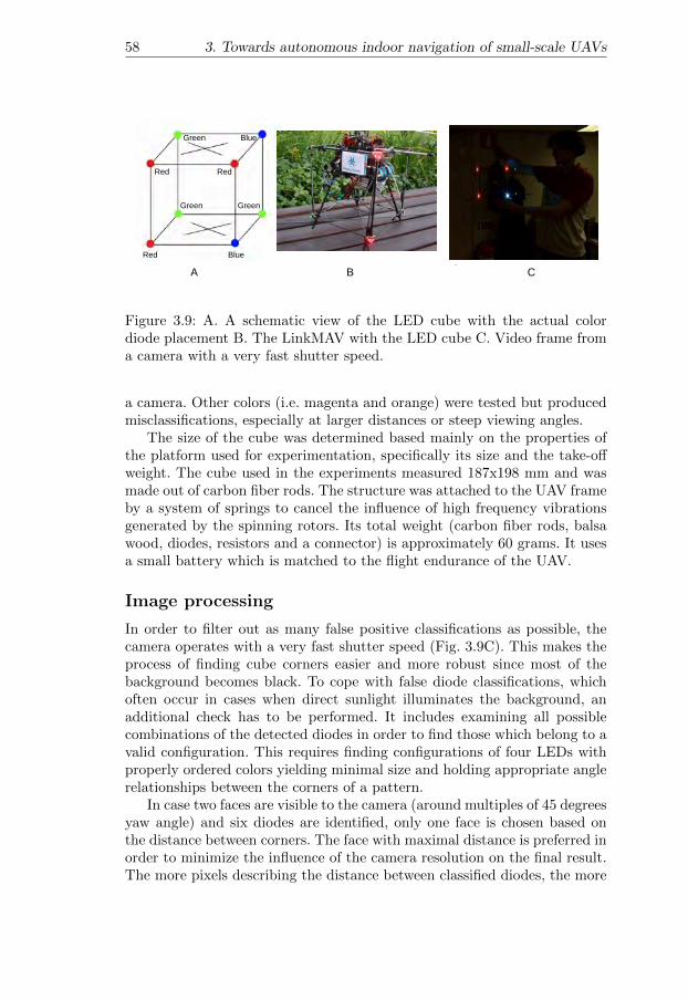
58 3. Towards autonomous indoor navigation of small-scale UAVs
!" #" $"Red
RedRed
Green Green
Green
Blue
Blue
A B C
Figure 3.9: A. A schematic view of the LED cube with the actual colordiode placement B. The LinkMAV with the LED cube C. Video frame froma camera with a very fast shutter speed.
a camera. Other colors (i.e. magenta and orange) were tested but producedmisclassifications, especially at larger distances or steep viewing angles.
The size of the cube was determined based mainly on the properties ofthe platform used for experimentation, specifically its size and the take-offweight. The cube used in the experiments measured 187x198 mm and wasmade out of carbon fiber rods. The structure was attached to the UAV frameby a system of springs to cancel the influence of high frequency vibrationsgenerated by the spinning rotors. Its total weight (carbon fiber rods, balsawood, diodes, resistors and a connector) is approximately 60 grams. It usesa small battery which is matched to the flight endurance of the UAV.
Image processing
In order to filter out as many false positive classifications as possible, thecamera operates with a very fast shutter speed (Fig. 3.9C). This makes theprocess of finding cube corners easier and more robust since most of thebackground becomes black. To cope with false diode classifications, whichoften occur in cases when direct sunlight illuminates the background, anadditional check has to be performed. It includes examining all possiblecombinations of the detected diodes in order to find those which belong to avalid configuration. This requires finding configurations of four LEDs withproperly ordered colors yielding minimal size and holding appropriate anglerelationships between the corners of a pattern.
In case two faces are visible to the camera (around multiples of 45 degreesyaw angle) and six diodes are identified, only one face is chosen based onthe distance between corners. The face with maximal distance is preferred inorder to minimize the influence of the camera resolution on the final result.The more pixels describing the distance between classified diodes, the more
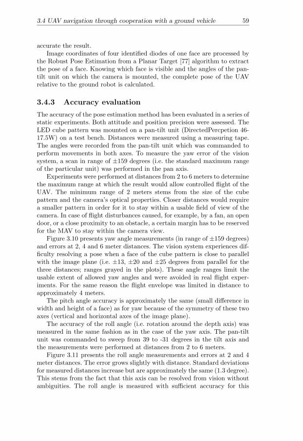
3.4 UAV navigation through cooperation with a ground vehicle 59
accurate the result.Image coordinates of four identified diodes of one face are processed by
the Robust Pose Estimation from a Planar Target [77] algorithm to extractthe pose of a face. Knowing which face is visible and the angles of the pan-tilt unit on which the camera is mounted, the complete pose of the UAVrelative to the ground robot is calculated.
3.4.3 Accuracy evaluation
The accuracy of the pose estimation method has been evaluated in a series ofstatic experiments. Both attitude and position precision were assessed. TheLED cube pattern was mounted on a pan-tilt unit (DirectedPercpetion 46-17.5W) on a test bench. Distances were measured using a measuring tape.The angles were recorded from the pan-tilt unit which was commanded toperform movements in both axes. To measure the yaw error of the visionsystem, a scan in range of ±159 degrees (i.e. the standard maximum rangeof the particular unit) was performed in the pan axis.
Experiments were performed at distances from 2 to 6 meters to determinethe maximum range at which the result would allow controlled flight of theUAV. The minimum range of 2 meters stems from the size of the cubepattern and the camera’s optical properties. Closer distances would requirea smaller pattern in order for it to stay within a usable field of view of thecamera. In case of flight disturbances caused, for example, by a fan, an opendoor, or a close proximity to an obstacle, a certain margin has to be reservedfor the MAV to stay within the camera view.
Figure 3.10 presents yaw angle measurements (in range of ±159 degrees)and errors at 2, 4 and 6 meter distances. The vision system experiences dif-ficulty resolving a pose when a face of the cube pattern is close to parallelwith the image plane (i.e. ±13, ±20 and ±25 degrees from parallel for thethree distances; ranges grayed in the plots). These angle ranges limit theusable extent of allowed yaw angles and were avoided in real flight exper-iments. For the same reason the flight envelope was limited in distance toapproximately 4 meters.
The pitch angle accuracy is approximately the same (small difference inwidth and height of a face) as for yaw because of the symmetry of these twoaxes (vertical and horizontal axes of the image plane).
The accuracy of the roll angle (i.e. rotation around the depth axis) wasmeasured in the same fashion as in the case of the yaw axis. The pan-tiltunit was commanded to sweep from 39 to -31 degrees in the tilt axis andthe measurements were performed at distances from 2 to 6 meters.
Figure 3.11 presents the roll angle measurements and errors at 2 and 4meter distances. The error grows slightly with distance. Standard deviationsfor measured distances increase but are approximately the same (1.3 degree).This stems from the fact that this axis can be resolved from vision withoutambiguities. The roll angle is measured with sufficient accuracy for this

60 3. Towards autonomous indoor navigation of small-scale UAVs
Yaw angle at 6 meters distance
-180
-90
0
90
180
1 201
Vision Reference
Yaw angle error at 6 meters distance
-50
-40
-30
-20
-10
0
10
20
30
40
50
1 201
Yaw angle error at 4 meters distance
-60
-50
-40
-30
-20
-10
0
10
20
1 201
Yaw angle at 4 meters distance
-180
-90
0
90
180
1 201
Vision Reference
Yaw angle at 2 meters distance
-180
-90
0
90
180
1 201
Vision Reference
Yaw angle error at 2 meters distance
-20
-15
-10
-5
0
5
10
1 201
Samples
Degrees
Samples
Degrees
Samples
Degrees
Samples
Degrees
SamplesDegrees
Samples
Degrees
Figure 3.10: Measured values and errors for the yaw axis a three distances.
application.The distance measurement was performed at distances from 1 to 5 me-
ters. For distances up to 3 meters, the error was smaller than the accuracyof the ground truth measurement (e.g. the exact placement of the CCD ele-ment of the camera is unknown). For distances of 4 and 5 meters the absoluteerror was approximately 13 and 45 centimeters, respectively. The absoluteerror and its standard deviation grows with distance because of the growingpenalty of the camera resolution (the ratio between physical distance be-tween diodes to number of pixels increases). Figure 3.12 presents distanceerror standard deviations for distances from 1 to 5 meters. It includes thecases where a pattern face is close to parallel with the image plane.
During a real flight, measurements are expected to be worse due to vi-brations of the platform and the LED pattern cube. For the flight testsperformed, however, it did not pose a noticeable problem. The final vision-only flight envelope is limited to approximately 4 meters distance and byposes where a cube pattern face is parallel to the camera plane as described
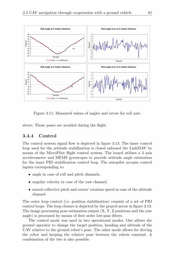
3.4 UAV navigation through cooperation with a ground vehicle 61
Roll angle at 2 meters distance
-40
-30
-20
-10
0
10
20
30
40
50
1 101
Vision Reference
Roll angle error at 2 meters distance
-6
-5
-4
-3
-2
-1
0
1
2
3
4
5
1 101
Roll angle at 4 meters distance
-40
-30
-20
-10
0
10
20
30
40
50
1 101
Vision Reference
Roll angle error at 4 meters distance
-4
-3
-2
-1
0
1
2
3
4
1 101
Samples
Degrees
Samples
Degrees
Samples
Degrees
Samples
Degrees
Figure 3.11: Measured values of angles and errors for roll axis.
above. Those poses are avoided during the flight.
3.4.4 Control
The control system signal flow is depicted in figure 3.13. The inner controlloop used for the attitude stabilization is closed onboard the LinkMAV bymeans of the MicroPilot flight control system. The board utilizes a 3 axisaccelerometer and MEMS gyroscopes to provide attitude angle estimationfor the inner PID stabilization control loop. The autopilot accepts controlinputs corresponding to:
• angle in case of roll and pitch channels,
• angular velocity in case of the yaw channel,
• mixed collective pitch and rotors’ rotation speed in case of the altitudechannel.
The outer loop control (i.e. position stabilization) consists of a set of PIDcontrol loops. The loop closure is depicted by the grayed arrow in figure 3.13.The image processing pose estimation output (X, Y, Z positions and the yawangle) is processed by means of first order low-pass filters.
The control mode was used in two operational modes. One allows theground operator to change the target position, heading and altitude of theUAV relative to the ground robot’s pose. The other mode allows for drivingthe robot and keeping the relative pose between the robots constant. Acombination of the two is also possible.

62 3. Towards autonomous indoor navigation of small-scale UAVs
Distance error standard deviation
0
10
20
30
40
50
60
70
1 2 3 4 5Distance m
mm
Figure 3.12: Standard deviation of distance error for several distances.
3.4.5 Experimental validation
Several hours of flight tests were performed with the described system. Twokinds of experiments are presented here to demonstrate the suitability ofthe system for realistic indoor missions. Test flights were performed with allparts of the system fully operational. No tethers or external power supplieswere used. The system was operated by a single ground operator who wascommanding the ground robot to drive to a certain location and placing theUAV in a desired relation to the ground robot. Autonomous take-off andlanding was not implemented and a backup pilot performed those parts ofthe mission manually. After the UAV entered into the view of the cameraand the system was initialized, the control was handed over to the system.
Exploration
This basic flight mode allows for exploring an environment. The groundoperator commands the UAV to place itself in a certain pose relative to theground robot. Then, the operator commands the ground robot to drive toa desired location. During the driving the UAV does not require any directcontrol input.
”Eye-in-the-sky”
The second flight presented here demonstrates an application of the systemas an extended camera which provides video footage from a position notaccessible from a ground robot’s point of view. A cardboard box was placedon the path of the ground robot simulating an obstacle. A person was lyingbehind the box and the task was to provide footage from behind the obstacle.The box was approximately one meter high and anything behind it was outof reach for the ground robot’s video camera.

3.4 UAV navigation through cooperation with a ground vehicle 63
Onboard MAV System
Flight ControlBoard
2.4GHzWirelessModem
R/CReceiver
Servos,Speed
Controllers
R/CTransmitter
Serial to PPMConverter
868MHzWirelessModem
Ground Robot System
Backup Pilot System
868MHzWirelessModem
GroundRobotComputer
ImageProcessing
Init
x, y, z, yaw
inner loopcontrol inputs
outer loopcontrol inputs
2.4GHzWirelessModem
Low-PassFilter
PID
Figure 3.13: Control flow diagram. The grayed arrow depicts the outer loopclosure.
Experimental results
Figure 3.14A shows six sample frames of the exploration task video. Theground robot drove approximately 10 meters, stopped and turned 40 degreesleft and continued driving forward. Throughout the whole time, the UAVkept a constant relative pose to the ground robot. The second task startedwith a straight drive of about 7 meters and ended with the ground vehiclearriving close to an obstacle. The LinkMAV was commanded to climb severaldecimeters above the box. After that, the UAV was commanded to fly 1meter forward to reach behind the obstacle. Despite turbulence generatedby the close distance between the UAV and the obstacle, the flight wasautonomous at all times. After the person behind the obstacle was spottedby the ground operator, the ground robot was commanded to return toits starting position. Three sample frames of the video are presented in

64 3. Towards autonomous indoor navigation of small-scale UAVs
A
B
Figure 3.14: Top 6: Frames of video of the system during exploration task.Bottom 3: Frames of video of the system reaching behind an obstacle.
figure 3.14B. The bottom-right image presents a frame from the onboardUAV thermal video with the identified human body.
The pose estimation algorithm runs at a frame-rate of around 20Hz andallows for controlling the UAV purely by vision.
3.4.6 Conclusion
A fully implemented and tested method for indoor UAS navigation hasbeen presented. The system is based on cooperating with a ground robotto facilitate the indoor localization of an aerial vehicle. The role of theground robot is to provide the UAV with location information. This kindof cooperation allows for taking advantage of the well developed techniquesfor ground robot localization together with the ability of a flying robot toposition its sensors in a way normally not available to a ground robot.

3.5 Marker-based visual pose estimation for indoor navigation 65
(0,0,0)
P1 P2
Figure 3.15: Schematic view of the marker-based visual pose estimation so-lution.
3.5 Marker-based visual pose estimation forindoor navigation
Solutions which require distributing components of the system among sev-eral wirelessly communicating hardware entities can be effective and allowfor indoor UAV navigation as shown in the previous section. Truly au-tonomous systems, however, should not rely on external help. This sectionpresents a solution to the indoor navigation problem which is computation-ally independent of other entities. All computations are done on-board asmall scale UAV.
The solution is based on a marker-based visual state estimation algo-rithm. It delivers a 6-DOF state of a camera on a vehicle in relation (solidlines in figure 3.15) to low-cost markers placed in the environment. Thevision-based state estimate is then fused with inertial data to provide thefull state estimate which is of higher rate and also includes velocities of thevehicle.
Thanks to incorporating a mapping functionality, the arbitrarily placedmarkers form a map (relations between markers depicted with dashed lines)of the environment and allow for navigation of a UAV within this map. Forexample, autonomous flight between two positions (P1 and P2 in figure 3.15)can be achieved because the state is calculated along the path (dotted line).
The remainder of this section is structured as follows. First, the maincomponents of the system are introduced in section 3.5.1, followed by thedescription of the marker-based visual pose estimation method includingthe technique which allows for mapping of the environment in sections 3.5.2and 3.5.3, respectively. Second, the sensor fusion method is introduced insection 3.5.4 and is followed by an evaluation of the accuracy of the methodin section 3.5.5. The control method used is described in section 3.5.6. Fi-nally, the results of the experimental validation are presented in section 3.5.7followed by the conclusions in section 3.5.8.

66 3. Towards autonomous indoor navigation of small-scale UAVs
Vision-based pose estimation
Video
Sensor fusion
Control
Inertial data
UAS platform
Figure 3.16: The main functional components of the system.
3.5.1 System overview
The main functional components of the system are shown in Figure 3.16.The vision-based pose estimation module makes use of a set of arbitrarilyplaced artificial markers which form a map of the operational environment.This module delivers the complete 6-DOF pose of a UAV i.e. 3D position and3 attitude angles. The implementation of the marker-based state estimationmodule is based on a library used in augmented reality applications, theARToolkitPlus15.
The pose information (excluding roll and pitch angles) is fused usinga Kalman filter with the inertial data (i.e. three accelerations and threeangular rates) to produce the full state of the system. It consists of the poseand 3 velocities (north, east and up). It is used as input to the control modulewhich implements the flight control modes (e.g. hovering and navigation toa given point).
The details of the system components are presented in the remainder ofthis section.
3.5.2 Pose estimation method
The process of calculating a pose is divided into two major steps, markerdetection and pose estimation. Marker detection is accomplished in the fol-lowing manner. First, rectangular regions in an image are found as hypothe-ses of legitimate markers (see Marker boundary in Figure 3.17B). Second,the interior of each hypothesis is analyzed in order to decode the identifyingnumber (see Figure 3.17B ID boundary). The goal of the marker detectionphase is to discern the ID and identify a sequence of the marker corners’ co-ordinates in the image. The pose estimation algorithm calculates the relation(rotational and translational) between the camera and the marker coordi-nate systems. The calculation is based on the coordinates of the detectedmarker corners (i.e. projection of the marker model on the image plane, cf.figure 3.17A).
Both steps of the vision-based pose estimation process perform differ-ently depending on the relation of the marker and the camera in terms oftranslations and rotations. For example, for certain distances and camera
15Homepage: studierstube.icg.tugraz.at/handheld_ar/artoolkitplus.php

3.5 Marker-based visual pose estimation for indoor navigation 67
!"#$%&'(#)%
*#"%+#
,#+-%+
.,
/,
0,
0*1,
.*1,
/*1,
/!,2
.!,2
A C
0
200
400
600
800
10000 200 400 600 800 1000
0
100
200
300
400
500
600
700
800
900
1000
X[mm]
Y[mm]
Z[m
m]
B
Marker boundary
ID boundary
Pi
pi2000
1800
1600
1400
1200
1000
800
600
400
200
400800
12001600
20002000
1600
1200
800
400
!"#$%&'(#)%
*#"%+#
,#+-%+
.,
/,
0,
0*1,
.*1,
/*1,
/!,2
.!,2
A C
0
200
400
600
800
10000 200 400 600 800 1000
0
100
200
300
400
500
600
700
800
900
1000
X[mm]
Y[mm]
Z[m
m]
B
Marker boundary
ID boundary
Pi
pi2000
1800
1600
1400
1200
1000
800
600
400
200
400800
12001600
20002000
1600
1200
800
400
!"#$%&'(#)%
*#"%+#
,#+-%+
.,
/,
0,
0*1,
.*1,
/*1,
/!,2
.!,2
A C
0
200
400
600
800
10000 200 400 600 800 1000
0
100
200
300
400
500
600
700
800
900
1000
X[mm]
Y[mm]
Z[m
m]
B
Marker boundary
ID boundary
Pi
pi2000
1800
1600
1400
1200
1000
800
600
400
200
400800
12001600
20002000
1600
1200
800
400
XM
[mm]
YM [mm]
Z M [m
m]
Figure 3.17: A. Vision-based pose estimation coordinate systems B. Exam-ple marker C. Camera positions (black dots) for the accuracy estimationexperiments.
attitudes estimating the pose is not possible at all or the result has a con-siderable error. The following subsections describe the process and resultsof evaluating the algorithm from the perspective of UAS navigation.
Marker detection
A marker ID can be coded in three different ways in the ARToolkitPluslibrary. The first one uses a template matching technique. This type is themost computationally and memory expensive since the interior of a detectedrectangle is compared with an image loaded at startup. For multiple markersall images have to be stored in memory for comparison. The second type,called Simple ID, supports 512 predefined markers and relies on decoding theID from an array of bits (e.g. 6×6) located inside the rectangular boundaryof a marker. The third type, called BCH ID (depicted in Figure 3.17B),encodes marker IDs using a forward correcting code and supports up to4096 combinations.
Both Simple and BCH ID coding methods were evaluated to assess theoptimal camera placement relative to a marker which assures reliable de-tection. A set of images was produced by projecting a marker (with linearinterpolation) of 100×100 mm size onto the image plane of a camera withimage size of 320×240 pixels, focal lengths fx = fy = 386 and the principalcx = cy = (160, 120).
The camera was placed as schematically depicted by black dots in Fig-ure 3.17C i.e. in 50 mm increments in XM and ZM directions up to 2 m.Three representative rotations around the ZM axis were used: 0, 22.5 and45 degrees (respectively, red, green and blue marked regions). The rotation

68 3. Towards autonomous indoor navigation of small-scale UAVs
0 500 1000 1500 20000
500
1000
1500
2000
distance to pattern [ mm]
Z [m
m]
Z rotation: 0 degrees
0.5
0.6
0.7
0.8
0.9
1
0 500 1000 1500 20000
500
1000
1500
2000
distance to pattern [ mm]
Z [m
m]
Z rotation: 22.5 degrees
0.5
0.6
0.7
0.8
0.9
1
0 500 1000 1500 20000
500
1000
1500
2000
distance to pattern [ mm]
Z [m
m]
Z rotation: 45 degrees
0.5
0.6
0.7
0.8
0.9
1
0 500 1000 1500 20000
500
1000
1500
2000
distance to pattern [ mm]
Z [m
m]
Z rotation: 0 degrees
0.5
0.6
0.7
0.8
0.9
1
0 500 1000 1500 20000
500
1000
1500
2000
distance to pattern [ mm]
Z [m
m]
Z rotation: 22.5 degrees
0.5
0.6
0.7
0.8
0.9
1
0 500 1000 1500 20000
500
1000
1500
2000
distance to pattern [ mm]
Z [m
m]
Z rotation: 45 degrees
0.5
0.6
0.7
0.8
0.9
1
Figure 3.18: BCH Marker detection confidence larger than 0.5 for threerotations around the ZM axis.
around the XCAM axis was chosen so that the camera was always pointingto the center of the marker which was located at the origin of the coordinatesystem. Marker detection was performed on the set of generated images.
The confidence of detecting a marker and decoding its ID for the threerotations around the ZM axis is shown in Figure 3.18. The confidence fordetecting BCH IDs is decreased from 1 by 0.25 for every detected and cor-rected error bit. Results with a confidence factor lower than 0.5 are notincluded in the plot. The result of detecting Simple IDs was on average13 percent worse i.e. detection was successful for fewer camera poses. Theuse of BCH markers adds almost no computational penalty and is preferredfor UAV navigation because it allows for the coverage of large operationalenvironments thanks to a larger number of available IDs.
In order to maximize the marker detection rate, the distance of the cam-era to a marker should not be larger than 75 cm for the given marker sizeand camera. Additionally, the image plane should not be tilted more thanapproximately 60 degrees from the marker. The area with high detectionrate is depicted by the dashed line in Figure 3.18.
The evaluation did not include the effects of lens distortion. However,with accurate camera calibration this is a minimal error contributor. Addi-tionally, the experimental setup did not include effects of blurring when thecamera moves relative to a marker. Depending on the imaging sensor usedthe effect of blooming or streaking can also influence the detection perfor-mance. However, both effects can be minimized by appropriately adjustingthe camera parameters as, for example, described in section 3.5.7.
Pose Estimation
After detecting a marker and extracting its four corners pi=1...4 =[pix , piy
]T
and given four coplanar model points Pi=1...4 =[Pix , Piy , 0
]Ta pose esti-
mation algorithm calculates the rotation expressed in Euler angles R =f (φ, θ, ψ) and translation t = [tx, ty, tz]
Tof a camera such that:
pi ∝ RPi + t (3.1)

3.5 Marker-based visual pose estimation for indoor navigation 69
Since pi is expressed in camera coordinates, it is in practice perturbed bynoise and measured in an image as pi.
In general, calculating a pose i.e. finding R and t can be achieved byminimizing one of the commonly used error functions. For example, an imagespace error function in case of bundle-adjustment algorithms or an objectspace error function (Eos) used in the Robust Pose Estimation Algorithmfor Planar Targets (RPP) [77] can be used. In the latter case, a specialparameterization allows one to deal with pose ambiguities with up to a50 percent better success rate over the standard definition. The algorithmuses an initial pose estimate and finds a second minimum of the Eos errorfunction. If it exists, the correct pose should yield the lower value of the errorfunction. Due to this property, the algorithm exhibits a considerably lower”jerkiness” in the calculated pose. While in augmented reality applicationsthis property gives a better visual result, for UAS navigation it gives morestability and robustness.
Initially, the accuracy and the noise of the RPP algorithm were assessedin a series of Monte Carlo simulations. Poses of the camera were the same asfor the marker detection experiments and are shown in Figure 3.17C. Themodel points Pi were projected onto the image plane for the given R andt and the camera model described earlier. The values of pi were calculatedby perturbing pi with a uniform noise of 2 pixels in 750 iterations. Theerror in attitude angle estimation was measured as a difference between thenominal values of (α, β, γ) and the average results of the algorithm in thepresence of noise. Similarly, the error of position and altitude was measuredas the difference between the nominal value of t and the average result inthe presence of noise. Figure 3.19 shows the standard deviation of the errorin three axes (columns tx, ty and tz) of the camera translation in the markercoordinate system with 2 pixel noise. The three rows correspond to the threerotations around the ZM axis as described earlier. The range of altitude anddistance to a marker were chosen to emphasize the range of marker detectiondescribed in the previous subsection.
The RPP algorithm exhibits a mean and standard deviation errors in arange of several centimeters for distances up to 50 cm for the given set ofparameters (i.e. 10 x 10 cm pattern size, 320 x 240 pixels image size). Theattitude angles are estimated with an average error below 3 degrees witha standard deviation below 6 degrees. In order to assess a usable range ofthe algorithm, the results can be “scaled”. For example, doubling the size ofthe pattern cuts the error in half or doubles the range. The same applies todoubling the resolution of the camera. For an image of size 640 x 480 pixelsand a pattern of size 50 x 50 cm, the error measured in centimeters can bereached for up to 5 meters.
The usable range can additionally be extended by fusing the vision resultwith inertial data. In such cases, increased noise from the vision result canbe handled by, for example, a Kalman filter.
The minimum distance to a marker depends on the field of view of the
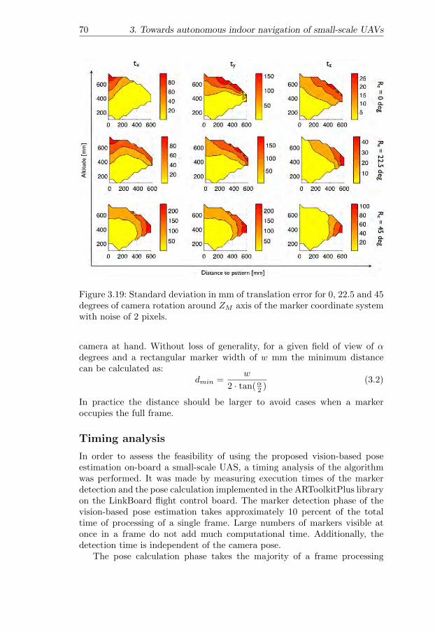
70 3. Towards autonomous indoor navigation of small-scale UAVs
Figure 3.19: Standard deviation in mm of translation error for 0, 22.5 and 45degrees of camera rotation around ZM axis of the marker coordinate systemwith noise of 2 pixels.
camera at hand. Without loss of generality, for a given field of view of αdegrees and a rectangular marker width of w mm the minimum distancecan be calculated as:
dmin =w
2 · tan(α2 )(3.2)
In practice the distance should be larger to avoid cases when a markeroccupies the full frame.
Timing analysis
In order to assess the feasibility of using the proposed vision-based poseestimation on-board a small-scale UAS, a timing analysis of the algorithmwas performed. It was made by measuring execution times of the markerdetection and the pose calculation implemented in the ARToolkitPlus libraryon the LinkBoard flight control board. The marker detection phase of thevision-based pose estimation takes approximately 10 percent of the totaltime of processing of a single frame. Large numbers of markers visible atonce in a frame do not add much computational time. Additionally, thedetection time is independent of the camera pose.
The pose calculation phase takes the majority of a frame processing
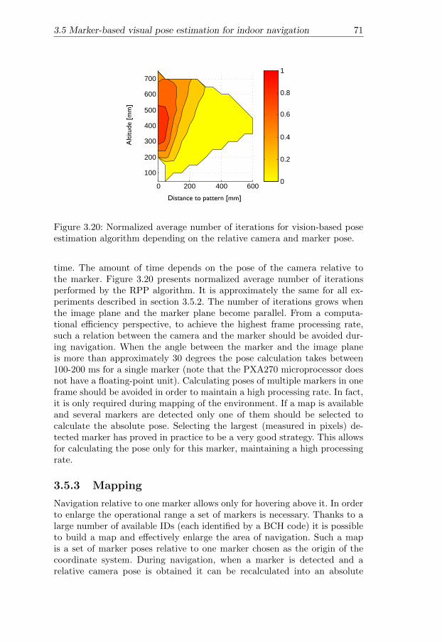
3.5 Marker-based visual pose estimation for indoor navigation 71
0 200 400 600
100
200
300
400
500
600
700
0
0.2
0.4
0.6
0.8
1
Distance to pattern [mm]
Altitude
[mm
]
Figure 3.20: Normalized average number of iterations for vision-based poseestimation algorithm depending on the relative camera and marker pose.
time. The amount of time depends on the pose of the camera relative tothe marker. Figure 3.20 presents normalized average number of iterationsperformed by the RPP algorithm. It is approximately the same for all ex-periments described in section 3.5.2. The number of iterations grows whenthe image plane and the marker plane become parallel. From a computa-tional efficiency perspective, to achieve the highest frame processing rate,such a relation between the camera and the marker should be avoided dur-ing navigation. When the angle between the marker and the image planeis more than approximately 30 degrees the pose calculation takes between100-200 ms for a single marker (note that the PXA270 microprocessor doesnot have a floating-point unit). Calculating poses of multiple markers in oneframe should be avoided in order to maintain a high processing rate. In fact,it is only required during mapping of the environment. If a map is availableand several markers are detected only one of them should be selected tocalculate the absolute pose. Selecting the largest (measured in pixels) de-tected marker has proved in practice to be a very good strategy. This allowsfor calculating the pose only for this marker, maintaining a high processingrate.
3.5.3 Mapping
Navigation relative to one marker allows only for hovering above it. In orderto enlarge the operational range a set of markers is necessary. Thanks to alarge number of available IDs (each identified by a BCH code) it is possibleto build a map and effectively enlarge the area of navigation. Such a mapis a set of marker poses relative to one marker chosen as the origin of thecoordinate system. During navigation, when a marker is detected and arelative camera pose is obtained it can be recalculated into an absolute

72 3. Towards autonomous indoor navigation of small-scale UAVs
pose in the environment. A map can be built online during environmentexploration. A straightforward way to build a map is to iteratively calculaterelative poses of newly detected markers in relation to the one chosen as theorigin. This requires two markers to be visible in the camera frame at once.The result of the pose estimation of two markers is given by the rotationmatrices c
mRi and translations cmti, i = 0, 1. The results describe marker
pose relative to the camera coordinate system. The camera pose relative toa marker can be calculated as m
c R = cmR
T and mc t = m
c R cmt. The relative
pose can be calculated as follows:
RR = mc R0
cmR1 (3.3)
tR = mc R0 (mc t1 −mc t0) (3.4)
These two values are saved. During navigation, when the i-th marker isobserved, the absolute pose (relative to the marker designated as the originM) can be calculated as follows:
cMR = RR
cmRi (3.5)
cM t = RR
mc ti + tR (3.6)
This method has a very small computational footprint but has a drawback.The error of the pose estimation accumulates in relative poses and growswith the distance from the marker chosen as the origin. In other words,the farther away from the origin, the larger the error of the absolute pose.The error can be minimized by measuring the relative displacement of twomarkers several times and using an average. This will make the error smallerbut will not eliminate it.
One solution to this problem is to employ a method for explicit loopclosure which in this case would be a relatively easy task due to the factthat loop detection is solved thanks to using unique IDs.
Another way to solve the problem could be to calculate a globally con-sistent map given all measurements as in [60]. This algorithm operates ona graph where markers are represented as vertices and relative poses of twomarkers as edges. It is more computationally expensive than the simple so-lution and is more suitable for offline calculation.
3.5.4 Sensor fusion
In order to provide a robust navigation solution, the position and headinginformation delivered by the vision-based pose estimation is fused with theinertial data (from 3-axis accelerometers and 3 rate gyroscopes) by meansof a 9 state Extended Kalman Filter (EKF). The use of pitch and roll anglesfrom vision could improve the accuracy of the state estimation but wouldincrease the computational load and was empirically proven not to be neces-sary to achieve good performance. The state of the system is represented by
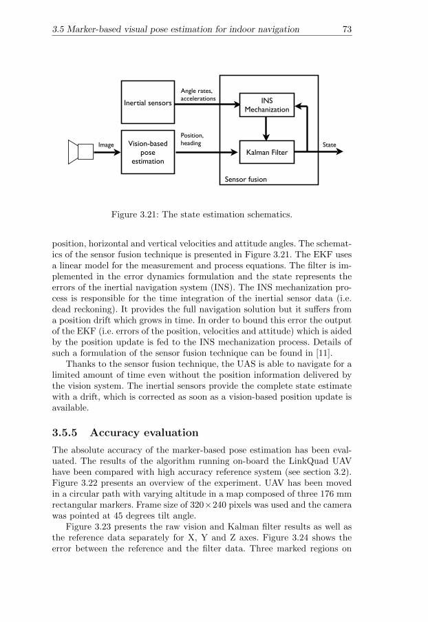
3.5 Marker-based visual pose estimation for indoor navigation 73
Vision-based pose
estimation
Position, headingImage
Inertial sensors
Angle rates, accelerations
State
Sensor fusion
INS Mechanization
Kalman Filter
Figure 3.21: The state estimation schematics.
position, horizontal and vertical velocities and attitude angles. The schemat-ics of the sensor fusion technique is presented in Figure 3.21. The EKF usesa linear model for the measurement and process equations. The filter is im-plemented in the error dynamics formulation and the state represents theerrors of the inertial navigation system (INS). The INS mechanization pro-cess is responsible for the time integration of the inertial sensor data (i.e.dead reckoning). It provides the full navigation solution but it suffers froma position drift which grows in time. In order to bound this error the outputof the EKF (i.e. errors of the position, velocities and attitude) which is aidedby the position update is fed to the INS mechanization process. Details ofsuch a formulation of the sensor fusion technique can be found in [11].
Thanks to the sensor fusion technique, the UAS is able to navigate for alimited amount of time even without the position information delivered bythe vision system. The inertial sensors provide the complete state estimatewith a drift, which is corrected as soon as a vision-based position update isavailable.
3.5.5 Accuracy evaluation
The absolute accuracy of the marker-based pose estimation has been eval-uated. The results of the algorithm running on-board the LinkQuad UAVhave been compared with high accuracy reference system (see section 3.2).Figure 3.22 presents an overview of the experiment. UAV has been movedin a circular path with varying altitude in a map composed of three 176 mmrectangular markers. Frame size of 320×240 pixels was used and the camerawas pointed at 45 degrees tilt angle.
Figure 3.23 presents the raw vision and Kalman filter results as well asthe reference data separately for X, Y and Z axes. Figure 3.24 shows theerror between the reference and the filter data. Three marked regions on
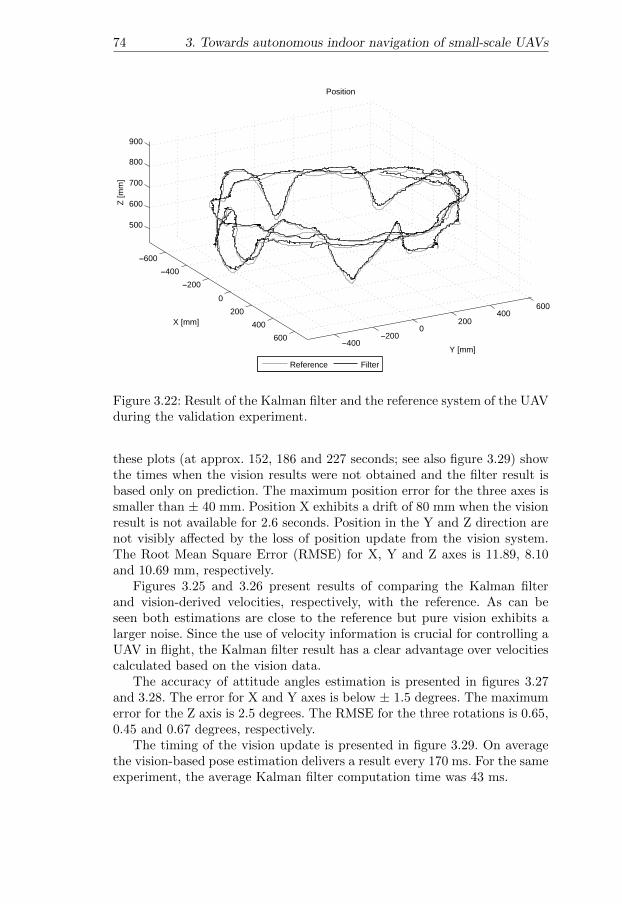
74 3. Towards autonomous indoor navigation of small-scale UAVs
−600−400
−2000
200400
600 −400−200
0200
400600
500
600
700
800
900
Y [mm]
Position
X [mm]
Z [m
m]
Reference Filter
Figure 3.22: Result of the Kalman filter and the reference system of the UAVduring the validation experiment.
these plots (at approx. 152, 186 and 227 seconds; see also figure 3.29) showthe times when the vision results were not obtained and the filter result isbased only on prediction. The maximum position error for the three axes issmaller than ± 40 mm. Position X exhibits a drift of 80 mm when the visionresult is not available for 2.6 seconds. Position in the Y and Z direction arenot visibly affected by the loss of position update from the vision system.The Root Mean Square Error (RMSE) for X, Y and Z axes is 11.89, 8.10and 10.69 mm, respectively.
Figures 3.25 and 3.26 present results of comparing the Kalman filterand vision-derived velocities, respectively, with the reference. As can beseen both estimations are close to the reference but pure vision exhibits alarger noise. Since the use of velocity information is crucial for controlling aUAV in flight, the Kalman filter result has a clear advantage over velocitiescalculated based on the vision data.
The accuracy of attitude angles estimation is presented in figures 3.27and 3.28. The error for X and Y axes is below ± 1.5 degrees. The maximumerror for the Z axis is 2.5 degrees. The RMSE for the three rotations is 0.65,0.45 and 0.67 degrees, respectively.
The timing of the vision update is presented in figure 3.29. On averagethe vision-based pose estimation delivers a result every 170 ms. For the sameexperiment, the average Kalman filter computation time was 43 ms.

3.5 Marker-based visual pose estimation for indoor navigation 75
140 150 160 170 180 190 200 210 220 230 240−600
−400
−200
0
200
400
600Position X
[mm
]
[s]
Vision Reference Filter
140 150 160 170 180 190 200 210 220 230 240−600
−400
−200
0
200
400
600
Position Y
[mm
]
[s]
140 150 160 170 180 190 200 210 220 230 240500
550
600
650
700
750
800
850Position Z
[mm
]
[s]
Figure 3.23: Raw vision, Kalman filter and the reference position in threeaxes. Vertical lines mark regions of vision results not available for longerthan 0.9 seconds.
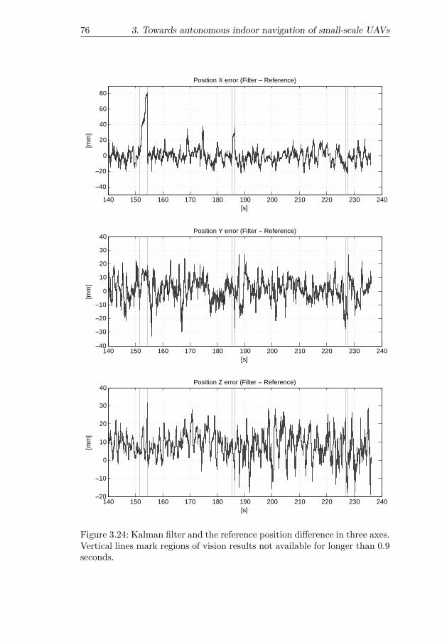
76 3. Towards autonomous indoor navigation of small-scale UAVs
140 150 160 170 180 190 200 210 220 230 240
−40
−20
0
20
40
60
80
Position X error (Filter − Reference)[m
m]
[s]
140 150 160 170 180 190 200 210 220 230 240−40
−30
−20
−10
0
10
20
30
40Position Y error (Filter − Reference)
[mm
]
[s]
140 150 160 170 180 190 200 210 220 230 240−20
−10
0
10
20
30
40Position Z error (Filter − Reference)
[mm
]
[s]
Figure 3.24: Kalman filter and the reference position difference in three axes.Vertical lines mark regions of vision results not available for longer than 0.9seconds.

3.5 Marker-based visual pose estimation for indoor navigation 77
140 150 160 170 180 190 200 210 220 230 240−200
−150
−100
−50
0
50
100
150
200Velocity X
[mm
/s]
[s]
Reference Filter
140 150 160 170 180 190 200 210 220 230 240−250
−200−150−100−50
0
50100150200250
Velocity Y
[mm
/s]
[s]
140 150 160 170 180 190 200 210 220 230 240−200
−150
−100
−50
0
50
100
150
200Velocity Z
[mm
/s]
[s]
Figure 3.25: Kalman filter and the reference velocities in three axes. Verticallines mark regions of vision results not available for longer than 0.9 seconds.
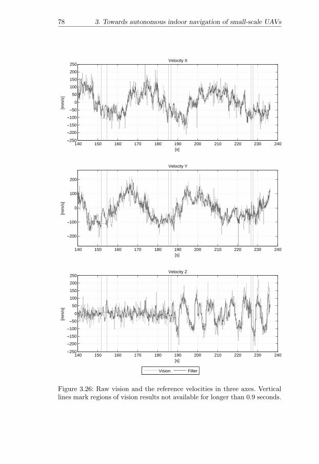
78 3. Towards autonomous indoor navigation of small-scale UAVs
140 150 160 170 180 190 200 210 220 230 240−250
−200−150−100−50
0
50100150200250
Velocity X[m
m/s
]
[s]
Vision Filter
140 150 160 170 180 190 200 210 220 230 240
−200
−100
0
100
200
Velocity Y
[mm
/s]
[s]
140 150 160 170 180 190 200 210 220 230 240−250
−200−150−100−50
0
50100150200250
Velocity Z
[mm
/s]
[s]
Figure 3.26: Raw vision and the reference velocities in three axes. Verticallines mark regions of vision results not available for longer than 0.9 seconds.

3.5 Marker-based visual pose estimation for indoor navigation 79
140 150 160 170 180 190 200 210 220 230 240
−2
−1
0
1
2
3
4
5
6
Roll
[deg
ree]
[s]
Reference Filter
140 150 160 170 180 190 200 210 220 230 240−6
−5
−4
−3
−2
−1
0
1Pitch
[deg
ree]
[s]
140 150 160 170 180 190 200 210 220 230 240−200
−150
−100
−50
0
50
100
150
200Yaw
[deg
ree]
[s]
Figure 3.27: Kalman filter and the reference attitude angles. Vertical linesmark regions of vision results not available for longer than 0.9 seconds.

80 3. Towards autonomous indoor navigation of small-scale UAVs
140 150 160 170 180 190 200 210 220 230 240−1.5
−1
−0.5
0
0.5
1
1.5Roll error (Filter − Reference)
[deg
ree]
[s]
140 150 160 170 180 190 200 210 220 230 240
−1
−0.5
0
0.5
1Pitch error (Filter − Reference)
[deg
ree]
[s]
140 150 160 170 180 190 200 210 220 230 240
−2
−1
0
1
2Yaw error (Filter − Reference)
[deg
ree]
[s]
Figure 3.28: Kalman filter and the reference attitude angles difference inthree axes. Vertical lines mark regions of vision results not available forlonger than 0.9 seconds.

3.5 Marker-based visual pose estimation for indoor navigation 81
140 150 160 170 180 190 200 210 220 230 2400
0.5
1
1.5
2
2.5
3Vision update time
[s]
[s]
0.17
Figure 3.29: Raw vision update timing.
The accuracy of the mapping method described in section 3.5.3 has beenevaluated as well. Figure 3.30 presents the X and Y plot of the Kalman filterresult and the reference. A set of 12 markers (176 mm) has been placed ina L shaped way as presented in figure 3.31. The UAV has been movedfrom the start position (above a marker placed in the origin of the referencesystem) along the L path of markers. Even though the used mapping methodaccumulates error the further away from the origin, the drift within the builtmap of 6× 3 meters was not visible.
3.5.6 Control
All computations in the system are executed on-board the UAS. The innercontrol loop (i.e. attitude stabilization) is performed by the Hummingbirdquadrotor platform electronics. It accepts input through a serial connectionin the form of angles in case of roll and pitch, angular velocity in case ofyaw and the thrust value of the altitude channel.
These signals are produced by the outer control loop (i.e. position sta-bilization) computed on the LinkBoard autopilot. Four PID control loopsare responsible for calculating the control signals. During initialization ofthe outer loop four initial control values are taken from the UAS avionics.They correspond to the values of the sticks of the RC transmitter when theUAS is operated manually. The initialization step is performed when theautonomous flight is engaged and results in a smooth transition betweenthe flight modes.

82 3. Towards autonomous indoor navigation of small-scale UAVs
0 1000 2000 3000 4000 5000
−500
0
500
1000
1500
2000
2500
X [mm]
Y [m
m]
Reference Filter
Start
End
Figure 3.30: Kalman filter and the reference position in X and Y directionsfor a larger map.
Figure 3.31: The marker setup used for evaluating the accuracy of the mapbuilding method. Vicon cameras of the reference system visible at the topof the image.

3.5 Marker-based visual pose estimation for indoor navigation 83
3.5.7 Experimental validation
The system has been evaluated in real flight tests using the Hummingbird-based UAV platform described in section 3.2 with all the described com-ponents operational. No tethers or other aids were used to validate theperformance of the system in fully autonomous flight.
Experimental setup
The flights were performed in an office environment. A set of 20 randomlyplaced artificial markers of size 17×17 cm printed on white paper (see Fig-ure 3.32) were used to compute a map of the environment. The map was con-structed on-line during an exploration flight using the procedure describedin section 3.5.3 and then saved for successive flights.
In order to minimize the influence of the ”rolling shutter” of CMOS sen-sors the camera parameters were adjusted to use the shortest possible expo-sure time. To compensate for the darker images the contrast and brightnessparameters were appropriately adjusted. Due to this, the typical skew andwobble effects were to a large extent removed from the images.
The camera was pointed 45 degrees down to achieve minimal pose es-timation error and a high processing rate (cf. section 3.5.2). The relationbetween the camera and the UAS coordinate systems was measured withcentimeter accuracy. This proved to be sufficient but for the best preci-sion the relation could be fully calibrated using, for example, the methoddescribed in Hol et al. [46].
The camera was calibrated to find intrinsic and lens distortion parame-ters using the Camera Calibration Toolbox for Matlab [9].
Several hours of autonomous flights were performed during developmentand evaluation of the system. The marker size used allowed for stable hov-ering up to approximately 1.5 m altitude at different positions and headingsin a 4×4 meters region. The results achieved confirm the simulation resultspresented in section 3.5.2. Since only 20 out of 4096 markers were used, theoperational range can be substantially extended in the future.
Experimental results
In order to achieve stable hovering, it was also necessary to include the esti-mated velocities especially for the horizontal control and to a lesser degreefor altitude. The yaw channel did not require velocity in the outer controlloop to achieve good performance. Due to battery power depletion over time,it was necessary to include the integral term of the PID controller, especiallyfor the altitude channel. Autonomous flights for up to 20 minutes (i.e. theUAV’s endurance) were achieved.
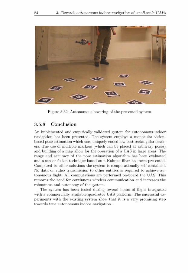
84 3. Towards autonomous indoor navigation of small-scale UAVs
Figure 3.32: Autonomous hovering of the presented system.
3.5.8 Conclusion
An implemented and empirically validated system for autonomous indoornavigation has been presented. The system employs a monocular vision-based pose estimation which uses uniquely coded low-cost rectangular mark-ers. The use of multiple markers (which can be placed at arbitrary poses)and building of a map allow for the operation of a UAS in large areas. Therange and accuracy of the pose estimation algorithm has been evaluatedand a sensor fusion technique based on a Kalman filter has been presented.Compared to other solutions the system is computationally self-contained.No data or video transmission to other entities is required to achieve au-tonomous flight. All computations are performed on-board the UAS. Thisremoves the need for continuous wireless communication and increases therobustness and autonomy of the system.
The system has been tested during several hours of flight integratedwith a commercially available quadrotor UAS platform. The successful ex-periments with the existing system show that it is a very promising steptowards true autonomous indoor navigation.

Chapter 4
Concluding remarks
The number of missions performed by autonomous UAS’s has been steadilygrowing the past decades. Progress is being made in both military, academicand commercial domains.
Outdoor operating autonomous UAS’s have reached a high level of matu-rity and the types of missions have become relatively sophisticated. Not onlydo they take off and execute 3D paths with high precision but also plan theirtrajectories and actions, to finally land without any human involvement.
This thesis presented two functionalities for outdoor operating UAS’swhich rely on color and thermal video streams as the main source of infor-mation. The first functionality deals with the problem of building saliencymaps where human body locations are marked as points of interest. Suchmaps can be used in emergency situations to help first responders to quicklyfocus the help effort in places where it is most needed. The task of acquir-ing the first overview of the situation can be delegated to autonomouslyoperating UAS’s.
The second functionality deals with tracking and geolocation of vehicles.The obtained streams of vehicle positions can be used by a reasoning systemto analyze traffic behaviors such as reckless overtakes, speeding and enter-ing crossings. Thanks to an automatic analysis of the traffic situation, theload on an operator can be greatly reduced and the situational awarenessimproved.
The use of UAS’s in indoor environments suffers from a major drawback,namely the lack of an ubiquitous positioning system such as the GPS. Forthis reason, the range of missions executed autonomously in indoor settingsis quite limited. Before the use of autonomous indoor aerial vehicles becomescommonplace, the problem of indoor pose estimation and localization hasto be solved.
This thesis presented two approaches to addressing these problems. Inboth solutions cameras are used as the main sensor. Their low cost, lightweight and low power consumption fit well with typical issues facing small
85
86 4. Concluding remarks
scale UAVs operating in indoor environments: smaller payloads, limitedpower sources and lower computational power. Both presented solutionshave been fully implemented and tested in series of flight tests demonstrat-ing their effectiveness.
The first approach relies on the cooperation between a UAV and a groundrobot system. The UGV uses its camera and a computer vision algorithmto compute the pose of the aerial vehicle and is responsible for controllingits flight. The UAV, in turn, acts as a remote sensor and allows the overallsystem to obtain sensory input not accessible for either of the componentson their own. Additionally, the use of a UAV in the presented way allowsfor building upon the development in the field of ground robotics by ex-tending the sensing capabilities of UGVs. The use of the presented systemin emergency situations, such as the recent nuclear power plant accident inJapan, would be very helpful in obtaining information (e.g. video feeds) notaccessible to ground robots.
In the second approach all computations are performed solely on theUAV and therefore there is no need for cooperation with other entities. Thesystem makes use of a marker-based visual state estimation and sensor fusiontechnique to provide a UAV with location information. The presented systemconstitutes, in fact, a low-cost indoor UAV testbed by solving the localizationproblem. Building upon the presented system, it is possible to pursue otheraspects of UAS use, such as control mode development (e.g. path execution)or applying artificial intelligence techniques (e.g. task and path planning).
4.1 Future work
Future work will involve further investigations of the indoor localizationproblem. The main objective will be to allow for fully autonomous indoorflight in unmodified environments. The key aspect to building a successfulsolution will be the use and fusion of different sensors’ data (e.g. from laserrange finders or optic flow sensors). A combination of several techniqueseach addressing a particular part of the problem should allow for a robustsolution to the indoor localization and navigation of UAVs.

Bibliography
[1] M. Achtelik, A. Bachrach, R. He, S. Prentice, and N. Roy. Stereo visionand laser odometry for autonomous helicopters in GPS-denied indoorenvironments. In Grant R. Gerhart, Douglas W. Gage, and Charles M.Shoemaker, editors, Unmanned Systems Technology XI, volume 7332,page 733219. SPIE, 2009.
[2] E. Altug, J. P. Ostrowski, and Camillo J. Taylor. Control of a quadrotorhelicopter using dual camera visual feedback. Int. J. Rob. Res., 24(5):329–341, 2005. ISSN 0278-3649.
[3] M. Andriluka, P. Schnitzspan, J. Meyer, S. Kohlbrecher, K. Petersen,O. von Stryk, S. Roth, and B. Schiele. Vision based victim detectionfrom unmanned aerial vehicles. In IEEE/RSJ International Conferenceon Intelligent Robots and Systems (IROS), pages 1740 –1747, oct. 2010.
[4] W. Bath and J. Paxman. UAV localisation & control through com-puter vision. In Proc. of the Australasian Conference on Robotics andAutomation, 2005.
[5] M. Blosch, S. Weiss, D. Scaramuzza, and R. Siegwart. Vision basedmav navigation in unknown and unstructured environments. In IEEEInternational Conference on Robotics and Automation (ICRA), pages21 –28, may. 2010.
[6] B. Bluteau, R. Briand, and O. Patrouix. Design and control of anoutdoor autonomous quadrotor powered by a four strokes rc engine. InIEEE Industrial Electronics, IECON 2006 - 32nd Annual Conferenceon, pages 4136 –4240, nov. 2006.
[7] S. Bouabdallah and A. Noth. PID vs LQ control techniques appliedto an indoor micro quadrotor. In IEEE International Conference onIntelligent Robots and Systems, pages 2451–2456, 2004.
[8] S. Bouabdallah, M. Becker, and V. De Perrot. Computer obstacle avoid-ance on quadrotors. In Proceedings of the XII International Symposiumon Dynamic Problems of Mechanics, 2007.
87

88 BIBLIOGRAPHY
[9] Jean-Yves Bouguet. Camera calibration toolbox for matlab., 2011.http://www.vision.caltech.edu/bouguetj/calib doc.
[10] K. Celik, Soon Jo Chung, and A. Somani. Mono-vision corner slamfor indoor navigation. In IEEE International Conference on Elec-tro/Information Technology, pages 343–348, May 2008.
[11] G. Conte. Vision-Based Localization and Guidance for UnmannedAerial Vehicles. PhD thesis, Linkoping UniversityLinkoping Univer-sity, Department of Computer and Information Science, The Instituteof Technology, 2009.
[12] G. Conte, S. Duranti, and T. Merz. Dynamic 3D Path Following for anAutonomous Helicopter. In Proc. of the IFAC Symposium on IntelligentAutonomous Vehicles, 2004.
[13] G. Conte, M. Hempel, P. Rudol, D. Lundstrom, S. Duranti, M. Wzorek,and P. Doherty. High accuracy ground target geo-location using au-tonomous micro aerial vehicle platforms. In AIAA Guidance, Navi-gation, and Control Conference, 2008, volume 26, Honolulu, Hawaii,2008.
[14] J. W. Davis and M. A. Keck. A Two-Stage Template Approach toPerson Detection in Thermal Imagery. In Workshop on Applications ofComputer Vision, 2005.
[15] L. de Souza Coelho and Mario F. M. Campos. Pose estimation ofautonomous dirigibles using artificial landmarks. In SIBGRAPI ’99:Proceedings of the XII Brazilian Symposium on Computer Graphics andImage Processing, pages 161–170, Washington, DC, USA, 1999. IEEEComputer Society. ISBN 0-7695-0481-7.
[16] R. Dechter, I. Meiri, and J. Pearl. Temporal constraint networks. AIJ,49, 1991.
[17] C.R. del Blanco, F. Jaureguizar, L. Salgado, and N. Garcia. Targetdetection through robust motion segmentation and tracking restrictionsin aerial flir images. In Image Processing, 2007. ICIP 2007. IEEEInternational Conference on, volume 5, pages V –445 –V –448, 16 2007-oct. 19 2007.
[18] P. Doherty. Advanced Research with Autonomous Unmanned AerialVehicles. In Proc. of the International Conference on the Principles ofKnowledge Representation and Reasoning, pages 731–732, 2004.
[19] P. Doherty and J. Kvarnstrom. Talplanner: A temporal logic basedplanner. AI MAGAZINE, 22:2001, 2001.

BIBLIOGRAPHY 89
[20] P. Doherty and P. Rudol. A UAV search and rescue scenario withhuman body detection and geolocalization. In AI’07: Proceedings of the20th Australian joint conference on Advances in artificial intelligence,pages 1–13, Berlin, Heidelberg, 2007. Springer-Verlag. ISBN 3-540-76926-9, 978-3-540-76926-2.
[21] P. Doherty, G. Granlund, K. Kuchinski, E. Sandewall, K. Nordberg,E. Skarman, and J. Wiklund. The WITAS unmanned aerial vehicleproject. In Proc. of the European Conf. on Artificial Intelligence, pages747–755, 2000.
[22] P. Doherty, P. Haslum, F. Heintz, T. Merz, P. Nyblom, T. Persson, andB. Wingman. A distributed architecture for autonomous unmannedaerial vehicle experimentation. In Proceedings of the 7th InternationalSymposium on Distributed Autonomous Robotic Systems, 2004.
[23] S. Duranti, G. Conte, D. Lundstrom, P. Rudol, M. Wzorek, and P. Do-herty. Linkmav, a prototype rotary wing micro aerial vehicle. InProceedings of the 17th IFAC Symposium on Automatic Control inAerospace, 2007.
[24] M. G. Earl and R. D’Andrea. Real-time attitude estimation techniquesapplied to a four rotor helicopter. In 43rd IEEE Conference on Decisionand Control, pages 3956–3961, Paradise Island, Bahamas, December2004.
[25] B. Erginer and E. Altug. Modeling and pd control of a quadrotor vtolvehicle. In Intelligent Vehicles Symposium, 2007 IEEE, pages 894 –899,june 2007.
[26] S. Fowers, D-J. Lee, B. Tippetts, K. D. Lillywhite, A. Dennis, andJ. Archibald. Vision aided stabilization and the development of a quad-rotor micro UAV. In Proc. of the 7th IEEE International Symposiumon Computational Intelligence in Robotics and Automation, pages 143–148, Paradise Island, Bahamas, June 2007.
[27] Y. Freund and R. E. Schapire. A decision-theoretic generalization of on-line learning and an application to boosting. In European Conferenceon Computational Learning Theory, 1995.
[28] M. Ghallab. On chronicles: Representation, on-line recognition andlearning. In Proceedings of the Fifth Intl Conf on Principles of Knowl-edge Representation and Reasoning, 1996. ISBN 1-55860-421-9.
[29] J.H. Gillula, H. Huang, M.P. Vitus, and C.J. Tomlin. Design of guaran-teed safe maneuvers using reachable sets: Autonomous quadrotor aer-obatics in theory and practice. In IEEE International Conference onRobotics and Automation (ICRA), pages 1649 –1654, May 2010.

90 BIBLIOGRAPHY
[30] M. A. Goodrich, J. L. Cooper, J. A. Adams, C. Humphrey, R. Zeeman,and Brian G. Buss. Using a Mini-UAV to Support Wilderness Searchand Rescue Practices for Human-Robot Teaming. In To appear in Pro-ceedings of the IEEE International Conference on Safety, Security andRescue Robotics, 2007.
[31] M. A. Goodrich, B. S. Morse, D. Gerhardt, J. L. Cooper, M. Quigley,J. A. Adams, and C. Humphrey. Supporting wilderness search andrescue using a camera-equipped mini uav: Research articles. J. FieldRobot., 25(1-2):89–110, 2008. ISSN 1556-4959.
[32] M. A. Goodrich, B. S. Morse, D. Gerhardt, J. L. Cooper, M. Quigley,J. A. Adams, and C. M. Humphrey. Supporting wilderness searchand rescue using a camera-equipped mini UAV. Journal of FieldRobotics, 25(1-2):89–110, 2008. ISSN 1556-4959. URL http://www3.
interscience.wiley.com/cgi-bin/fulltext/117865012/PDFSTART.
[33] S. Grzonka, G. Grisetti, and W. Burgard. Towards a navigation systemfor autonomous indoor flying. In IEEE International Conference onRobotics and Automation (ICRA), Kobe, Japan, 2009.
[34] D. Gurdan, J. Stumpf, M. Achtelik, K.-M. Doth, G. Hirzinger, andD. Rus. Energy-efficient autonomous four-rotor flying robot controlledat 1 khz. In IEEE International Conference on Robotics and Automa-tion, pages 361–366, April 2007.
[35] J. Han and B. Bhanu. Detecting moving humans using color and in-frared video. In IEEE International Conference on Multisensor Fusionand Integration for Intelligent Systems, 2003.
[36] R. I. Hartley and A. Zisserman. Multiple View Geometry in ComputerVision. Cambridge University Press, ISBN: 0521540518, second edition,2004.
[37] R. He, S. Prentice, and N. Roy. Planning in information space for aquadrotor helicopter in a GPS-denied environment. In IEEE Inter-national Conference on Robotics and Automation (ICRA), pages 1814–1820, May 2008.
[38] R. He, A. Bachrach, and N. Roy. Efficient planning under uncertaintyfor a target-tracking micro-aerial vehicle. In IEEE International Con-ference on Robotics and Automation (ICRA), pages 1–8, 2010.
[39] F. Heintz and P. Doherty. DyKnow: An approach to middleware forknowledge processing. Journal of Intelligent and Fuzzy Systems, 15(1):3–13, October 2004.
[40] F. Heintz and P. Doherty. A knowledge processing middleware frame-work and its relation to the JDL data fusion model. In Peter Funk,

BIBLIOGRAPHY 91
editor, Proceedings of the Swedish Artificial Intelligence and LearningSystems Workshop 2005, pages 68–77, April 2005.
[41] F. Heintz, P. Rudol, and P. Doherty. Bridging the sense-reasoning gapusing dyknow: A knowledgeprocessing middleware framework. In KI,pages 460–463, 2007.
[42] F. Heintz, P. Rudol, and P. Doherty. From images to traffic behavior- a UAV tracking and monitoring application. In Information Fusion,2007 10th International Conference on, pages 1–8, July 2007.
[43] H. Helble and S. Cameron. Oats: Oxford aerial tracking system.Robotics and Autonomous Systems, 55(9):661–666, 2007.
[44] G. M. Hoffmann, H. Huang, S. L. Waslander, and C. J. Tomlin. Quadro-tor helicopter flight dynamics and control: Theory and experiment. InIn Proc. of the AIAA Guidance, Navigation, and Control Conference,2007.
[45] G.M. Hoffmann, S.L. Waslander, and C.J. Tomlin. Mutual informationmethods with particle filters for mobile sensor network control. In De-cision and Control, 2006 45th IEEE Conference on, pages 1019 –1024,dec. 2006.
[46] J. Hol, T. Schon, and F. Gustafsson. A new algorithm for calibrating acombined camera and imu sensor unit. In Proc. of the 10th InternationalConference on Control, Automation, Robotics and Vision (ICARCV),Hanoi, Vietnam, December 2008.
[47] L. Hong, Y. Ruan, W. Li, D. Wicker, and J. Layne. Energy-basedvideo tracking using joint target density processing with an applicationto unmanned aerial vehicle surveillance. Computer Vision, IET, 2(1):1–12, march 2008. ISSN 1751-9632.
[48] J.P. How, B. Bethke, A. Frank, D. Dale, and J. Vian. Real-time in-door autonomous vehicle test environment. Control Systems Magazine,IEEE, 28(2):51 –64, apr. 2008. ISSN 0272-1708.
[49] H. Huang, G.M. Hoffmann, S.L. Waslander, and C.J. Tomlin. Aerody-namics and control of autonomous quadrotor helicopters in aggressivemaneuvering. In IEEE International Conference on Robotics and Au-tomation (ICRA), pages 3277 –3282, May 2009.
[50] J. Kang, K. Gajera, I. Cohen, and G. Medioni. Detection and Trackingof Moving Objects from Overlapping EO and IR Sensors. In Proceedingsof the 2004 Conference on Computer Vision and Pattern RecognitionWorkshop (CVPRW’04), 2004.
92 BIBLIOGRAPHY
[51] Jinman Kang, I. Cohen, G. Medioni, and Chang Yuan. Detection andtracking of moving objects from a moving platform in presence of strongparallax. In Computer Vision, 2005. ICCV 2005. Tenth IEEE Inter-national Conference on, volume 1, pages 10 – 17 Vol. 1, oct. 2005.
[52] B. Kim, M. Kaess, L. Fletcher, J. Leonard, A. Bachrach, N. Roy, andS. Teller. Multiple relative pose graphs for robust cooperative map-ping. In IEEE International Conference on Robotics and Automation(ICRA), pages 3185 –3192, May 2010.
[53] J. Kim and G. Brambley. Dual optic-flow integrated navigation forsmall-scale flying robots. In Proc. of the Australasian Conference onRobotics and Automation (ACRA’07), 2007.
[54] A. Kleiner, C. Dornhege, R. Kumerle, M. Ruhnke, B. Steder, B. Nebel,P. Doherty, M. Wzorek, P. Rudol, G. Conte, S. Durante, , and D. Lund-str”om. Robocuprescue - robot league team rescuerobots freiburg (ger-many). In RoboCup 2006 (CDROM Proceedings), Team DescriptionPaper, Rescue Robot League, 2006.
[55] H. Kruppa, M. Castrillon-Santana, and B. Schiele. Fast and robustface finding via local context. In Joint IEEE International Workshopon Visual Surveillance and Performance Evaluation of Tracking andSurveillance, October 2003.
[56] S. Lange, Sunderhauf N., P. Neubert, S. Drews, and P. Protzel. Au-tonomous corridor flight of a UAV using a low-cost and light-weightrgb-d camera. In International Symposium on Autonomous Minirobotsfor Research and Edutainment (AMiRE), 2011.
[57] D. J. Lee, P. Zhan, A. Thomas, and R. Schoenberger. Shape-based hu-man intrusion detection. In SPIE International Symposium on Defenseand Security, Visual Information Processing XIII, 2004.
[58] Y. Li. Vehicle extraction using histogram and genetic algorithm basedfuzzy image segmentation from high resolution UAV aerial imagery. InISPRS08, page B3b: 529 ff, 2008.
[59] R. Lienhart and J. Maydt. An Extended Set of Haar-like Features forRapid Object Detection. In Proceedings of International Conference onImage Processing, pages 900–903, 2002.
[60] F. Lu and E. Milios. Globally consistent range scan alignment forenvironment mapping. Autonomous Robots, 4:333–349, 1997.
[61] S. Lupashin, A. Schollig, M. Sherback, and R. D’Andrea. A simplelearning strategy for high-speed quadrocopter multi-flips. In IEEEInternational Conference on Robotics and Automation (ICRA), pages1642–1648, 2010.

BIBLIOGRAPHY 93
[62] P Mantegazza et. al. RTAI: Real time application interface. LinuxJournal, 72, April 2000.
[63] T. Merz, S. Duranti, and G. Conte. Autonomous landing of an un-manned helicopter based on vision and inertial sensing. In Proceedingsof 2004 International Symposium on Experimental Robotics, pages 343–352, 2004.
[64] T. Merz, P. Rudol, and M. Wzorek. Control system framework for au-tonomous robots based on extended state machines. In Autonomic andAutonomous Systems, International Conference on, volume 0, page 14,Los Alamitos, CA, USA, 2006. IEEE Computer Society. ISBN 0-7695-2653-5.
[65] N. Michael, D. Mellinger, Q. Lindsey, and V. Kumar. The GRASPmultiple micro UAV testbed. IEEE Robotics and Automation Magazine,2010.
[66] K. Mikolajczyk, C. Schmid, and A. Zisserman. Human Detection Basedon a Probabilistic Assembly of Robust Part Detectors. In EuropeanConference on Computer Vision, 2004.
[67] P. Nyblom. A language translator for robotic task procedure specifica-tions. Master’s thesis, Linkoping University, 2003.
[68] O. Purwin and R. D’Andrea. Performing aggressive maneuvers using it-erative learning control. In IEEE International Conference on Roboticsand Automation (ICRA), pages 1731–1736, 2009.
[69] G.V. Raffo, M.G. Ortega, and F.R. Rubio. Backstepping/nonlinear hinfcontrol for path tracking of a quadrotor unmanned aerial vehicle. InAmerican Control Conference, 2008, pages 3356 –3361, june 2008.
[70] N.D. Rasmussen, B.S. Morse, M. A. Goodrich, and D. Eggett. Fusedvisible and infrared video for use in wilderness search and rescue. InIEEE Workshop on Applications of Computer Vision (WACV), pages1–8, 2009.
[71] J. F. Roberts, T. Stirling, J-C. Zufferey, and D. Floreano. QuadrotorUsing Minimal Sensing For Autonomous Indoor Flight. In EuropeanMicro Air Vehicle Conference and Flight Competition (EMAV2007),2007. URL www.mav07.org.
[72] P. Rudol and P. Doherty. Human body detection and geolocalizationfor UAV search and rescue missions using color and thermal imagery.In Proceedings of the IEEE Aerospace Conference, 2008.
[73] P. Rudol, M. Wzorek, G. Conte, and P. Doherty. Micro unmannedaerial vehicle visual servoing for cooperative indoor exploration. InProceedings of the IEEE Aerospace Conference, pages 1–10, March 2008.

94 BIBLIOGRAPHY
[74] P. Rudol, M. Wzorek, R. Zalewski, and P. Doherty. Report on sense andavoid techniques and the prototype sensor suite. Technical report, Na-tional Aeronautics Research Program NFFP04-031, Autonomous flightcontrol and decision making capabilities for Mini-UAVs, 2008.
[75] P. Rudol, M. Wzorek, and P. Doherty. Vision-based pose estimationfor autonomous indoor navigation of micro-scale unmanned aircraft sys-tems. In IEEE International Conference on Robotics and Automation,ICRA 2010, pages 1913–1920, May 2010.
[76] E. Saad, J. Vian, G. Clark, and S. Bieniawski. Vehicle swarm rapidprototyping test-bed. In Proc. AIAA Infotech@Aerospace Conferenceand Exhibit, 2009.
[77] G. Schweighofer and A. Pinz. Robust pose estimation from a planartarget. In IEEE Transactions on Pattern Analysis and Machine In-telligence, volume 28, pages 2024–2030, Los Alamitos, CA, USA, 2006.IEEE Computer Society.
[78] A. Soumelidis, P. Gaspar, G. Regula, and B. Lantos. Control of anexperimental mini quad-rotor uav. In Control and Automation, 200816th Mediterranean Conference on, pages 1252 –1257, june 2008.
[79] P. Theodorakopoulos and S. Lacroix. A strategy for tracking a groundtarget with a UAV. In Intelligent Robots and Systems, 2008. IROS2008. IEEE/RSJ International Conference on, pages 1254 –1259, sept.2008.
[80] S. Thrun, M. Montemerlo, H. Dahlkamp, D. Stavens, A. Aron, J. Diebel,P. Fong, J. Gale, M. Halpenny, G. Hoffmann, K. Lau, C. Oakley,M. Palatucci, V. Pratt, P. Stang, S. Strohband, C. Dupont, L.-E. Jen-drossek, C. Koelen, C. Markey, C. Rummel, J. van Niekerk, E. Jensen,P. Alessandrini, G. Bradski, B. Davies, S. Ettinger, A. Kaehler, A. Ne-fian, and P. Mahoney. Stanley: The robot that won the DARPA GrandChallenge. Journal of Field Robotics, 23(9):661–692, September 2006.
[81] G. Tournier, M. Valenti, J. P. How, and E. Feron. Estimation and con-trol of a quadrotor vehicle using monocular vision and moire patterns.In AIAA Guidance, Navigation and Control Conference, 2006.
[82] P. Viola and M. J. Jones. Rapid Object Detection using a BoostedCascade of Simple Features. In Proceedings of Conference on ComputerVision and Pattern Recognition, 2001.
[83] S. Waharte and N. Trigoni. Supporting search and rescue operationswith UAVs. In International Symposiom on Robots and Security, 2010.
[84] A. Wendel, A. Irschara, and H. Bischof. Natural landmark-basedmonocular localization for mavs. In IEEE International Conferenceon Robotics and Automation (ICRA), 2011.

BIBLIOGRAPHY 95
[85] K. Wai Weng and M.S.B. Abidin. Design and control of a quad-rotorflying robot for aerial surveillance. In Research and Development, 2006.SCOReD 2006. 4th Student Conference on, pages 173 –177, june 2006.
[86] C. Wengert. A fully automatic camera and hand eye cali-bration, 2011. URL http://www.vision.ee.ethz.ch/software/
calibration_toolbox/calibration_toolbox.php.
[87] K. Wenzel, P. Rosset, and A. Zell. Low-cost visual tracking of a landingplace and hovering flight control with a microcontroller. Journal ofIntelligent and Robotic Systems, 57:297–311, 2010. ISSN 0921-0296.10.1007/s10846-009-9355-5.
[88] K. Engelbert Wenzel, A. Masselli, and A. Zell. Automatic take off,tracking and landing of a miniature UAV on a moving carrier vehicle.J. Intell. Robotics Syst., 61:221–238, January 2011. ISSN 0921-0296.
[89] M. Wzorek and P. Doherty. A framework for reconfigurable path plan-ning for autonomous unmanned aerial vehicles. Journal of Applied Ar-tificial Intelligence, 2007.
[90] M. Wzorek, G. Conte, P. Rudol, T. Merz, S. Duranti, and P. Doherty.From motion planning to control - a navigation framework for an au-tonomous unmanned aerial vehicle. In Proceedings of the 21th BristolInternational UAV Systems Conference, 2006.
[91] W.S. Yu, X. Yu, P.Q. Zhang, and J. Zhou. A new framework of movingtarget detection and tracking for UAV video application. In Interna-tional Society for Photogrammetry and Remote Sensing Congress, pageB3b: 609 ff, 2008.
[92] T. Zhang, Ye Kang, M. Achtelik, K. Kuhnlenz, and M. Buss. Au-tonomous hovering of a vision/imu guided quadrotor. In InternationalConference on Mechatronics and Automation (ICMA), pages 2870 –2875, aug. 2009.
[93] T. Zhang, W. Li, M. Achtelik, K. Kuhnlenz, and M. Buss. Multi-sensory motion estimation and control of a mini-quadrotor in an air-ground multi-robot system. In 2009 IEEE International Conference onRobotics and Biomimetics (ROBIO), pages 45 –50, dec. 2009.
[94] J. Zhou and J. Hoang. Real time robust human detection and trackingsystem. In IEEE Computer Society Conference on Computer Visionand Pattern Recognition (CVPR) Workshop, page 149, june 2005.
[95] Q. Zhu, M. C. Yeh, K. T. Cheng, and S. Avidan. Fast Human DetectionUsing a Cascade of Histograms of Oriented Gradients. In ComputerVision and Pattern Recognition, 2006.

96 BIBLIOGRAPHY
[96] S. Zingg, D. Scaramuzza, S. Weiss, and R. Siegwart. Mav navigationthrough indoor corridors using optical flow. In IEEE InternationalConference on Robotics and Automation (ICRA), may 2010.
Avdelning, InstitutionDivision, Department
DatumDate
Sprak
Language
� Svenska/Swedish
� Engelska/English
�
RapporttypReport category
� Licentiatavhandling
� Examensarbete
� C-uppsats
� D-uppsats
� Ovrig rapport
�
URL for elektronisk version
ISBN
ISRN
Serietitel och serienummerTitle of series, numbering
ISSN
Linkoping Studies in Science and Technology
Thesis No. 1510
TitelTitle
ForfattareAuthor
SammanfattningAbstract
NyckelordKeywords
The range of missions performed by Unmanned Aircraft Systems (UAS) hasbeen steadily growing in the past decades thanks to continued development inseveral disciplines. The goal of increasing the autonomy of UAS’s is wideningthe range of tasks which can be carried out without, or with minimal, externalhelp. This thesis presents methods for increasing specific aspects of autonomyof UAS’s operating both in outdoor and indoor environments where camerasare used as the primary sensors.
First, a method for fusing color and thermal images for object detection,geolocation and tracking for UAS’s operating primarily outdoors is presented.Specifically, a method for building saliency maps where human body locationsare marked as points of interest is described. Such maps can be used in emer-gency situations to increase the situational awareness of first responders or arobotic system itself. Additionally, the same method is applied to the problemof vehicle tracking. A generated stream of geographical locations of trackedvehicles increases situational awareness by allowing for qualitative reasoningabout, for example, vehicles overtaking, entering or leaving crossings.
Second, two approaches to the UAS indoor localization problem in the ab-sence of GPS-based positioning are presented. Both use cameras as the mainsensors and enable autonomous indoor flight and navigation. The first ap-proach takes advantage of cooperation with a ground robot to provide a UASwith its localization information. The second approach uses marker-based vi-sual pose estimation where all computations are done onboard a small-scaleaircraft which additionally increases its autonomy by not relying on externalcomputational power.
AIICS,Department of Computerand Information Science581 83 Linkoping
2011-11-04
978-91-7393-034-5
LiU-Tek-Lic–2011:49
0280–7971
http://urn.kb.se/resolve?urn=urn:nbn:se:liu:diva-71295
Increasing Autonomy of Unmanned Aircraft Systems Through the Useof Imaging Sensors
Piotr Rudol
××
UAV, UAS, UAV autonomy, human-body detection, color-thermal im-age fusion, vehicle tracking, geolocation, UAV indoor navigation


Department of Computer and Information Science
Linköpings universitet
Licentiate Theses
Linköpings Studies in Science and Technology
Faculty of Arts and Sciences
No 17 Vojin Plavsic: Interleaved Processing of Non-Numerical Data Stored on a Cyclic Memory. (Available at: FOA,
Box 1165, S-581 11 Linköping, Sweden. FOA Report B30062E)
No 28 Arne Jönsson, Mikael Patel: An Interactive Flowcharting Technique for Communicating and Realizing Al-
gorithms, 1984.
No 29 Johnny Eckerland: Retargeting of an Incremental Code Generator, 1984.
No 48 Henrik Nordin: On the Use of Typical Cases for Knowledge-Based Consultation and Teaching, 1985.
No 52 Zebo Peng: Steps Towards the Formalization of Designing VLSI Systems, 1985.
No 60 Johan Fagerström: Simulation and Evaluation of Architecture based on Asynchronous Processes, 1985.
No 71 Jalal Maleki: ICONStraint, A Dependency Directed Constraint Maintenance System, 1987.
No 72 Tony Larsson: On the Specification and Verification of VLSI Systems, 1986.
No 73 Ola Strömfors: A Structure Editor for Documents and Programs, 1986.
No 74 Christos Levcopoulos: New Results about the Approximation Behavior of the Greedy Triangulation, 1986.
No 104 Shamsul I. Chowdhury: Statistical Expert Systems - a Special Application Area for Knowledge-Based Computer
Methodology, 1987.
No 108 Rober Bilos: Incremental Scanning and Token-Based Editing, 1987.
No 111 Hans Block: SPORT-SORT Sorting Algorithms and Sport Tournaments, 1987.
No 113 Ralph Rönnquist: Network and Lattice Based Approaches to the Representation of Knowledge, 1987.
No 118 Mariam Kamkar, Nahid Shahmehri: Affect-Chaining in Program Flow Analysis Applied to Queries of Pro-
grams, 1987.
No 126 Dan Strömberg: Transfer and Distribution of Application Programs, 1987.
No 127 Kristian Sandahl: Case Studies in Knowledge Acquisition, Migration and User Acceptance of Expert Systems,
1987.
No 139 Christer Bäckström: Reasoning about Interdependent Actions, 1988.
No 140 Mats Wirén: On Control Strategies and Incrementality in Unification-Based Chart Parsing, 1988.
No 146 Johan Hultman: A Software System for Defining and Controlling Actions in a Mechanical System, 1988.
No 150 Tim Hansen: Diagnosing Faults using Knowledge about Malfunctioning Behavior, 1988.
No 165 Jonas Löwgren: Supporting Design and Management of Expert System User Interfaces, 1989.
No 166 Ola Petersson: On Adaptive Sorting in Sequential and Parallel Models, 1989.
No 174 Yngve Larsson: Dynamic Configuration in a Distributed Environment, 1989.
No 177 Peter Åberg: Design of a Multiple View Presentation and Interaction Manager, 1989.
No 181 Henrik Eriksson: A Study in Domain-Oriented Tool Support for Knowledge Acquisition, 1989.
No 184 Ivan Rankin: The Deep Generation of Text in Expert Critiquing Systems, 1989.
No 187 Simin Nadjm-Tehrani: Contributions to the Declarative Approach to Debugging Prolog Programs, 1989.
No 189 Magnus Merkel: Temporal Information in Natural Language, 1989.
No 196 Ulf Nilsson: A Systematic Approach to Abstract Interpretation of Logic Programs, 1989.
No 197 Staffan Bonnier: Horn Clause Logic with External Procedures: Towards a Theoretical Framework, 1989.
No 203 Christer Hansson: A Prototype System for Logical Reasoning about Time and Action, 1990.
No 212 Björn Fjellborg: An Approach to Extraction of Pipeline Structures for VLSI High-Level Synthesis, 1990.
No 230 Patrick Doherty: A Three-Valued Approach to Non-Monotonic Reasoning, 1990.
No 237 Tomas Sokolnicki: Coaching Partial Plans: An Approach to Knowledge-Based Tutoring, 1990.
No 250 Lars Strömberg: Postmortem Debugging of Distributed Systems, 1990.
No 253 Torbjörn Näslund: SLDFA-Resolution - Computing Answers for Negative Queries, 1990.
No 260 Peter D. Holmes: Using Connectivity Graphs to Support Map-Related Reasoning, 1991.
No 283 Olof Johansson: Improving Implementation of Graphical User Interfaces for Object-Oriented Knowledge- Bases,
1991.
No 298 Rolf G Larsson: Aktivitetsbaserad kalkylering i ett nytt ekonomisystem, 1991.
No 318 Lena Srömbäck: Studies in Extended Unification-Based Formalism for Linguistic Description: An Algorithm for
Feature Structures with Disjunction and a Proposal for Flexible Systems, 1992.
No 319 Mikael Pettersson: DML-A Language and System for the Generation of Efficient Compilers from Denotational
Specification, 1992.
No 326 Andreas Kågedal: Logic Programming with External Procedures: an Implementation, 1992.
No 328 Patrick Lambrix: Aspects of Version Management of Composite Objects, 1992.
No 333 Xinli Gu: Testability Analysis and Improvement in High-Level Synthesis Systems, 1992.
No 335 Torbjörn Näslund: On the Role of Evaluations in Iterative Development of Managerial Support Systems, 1992.
No 348 Ulf Cederling: Industrial Software Development - a Case Study, 1992.
No 352 Magnus Morin: Predictable Cyclic Computations in Autonomous Systems: A Computational Model and Im-
plementation, 1992.
No 371 Mehran Noghabai: Evaluation of Strategic Investments in Information Technology, 1993.
No 378 Mats Larsson: A Transformational Approach to Formal Digital System Design, 1993.

No 380 Johan Ringström: Compiler Generation for Parallel Languages from Denotational Specifications, 1993.
No 381 Michael Jansson: Propagation of Change in an Intelligent Information System, 1993.
No 383 Jonni Harrius: An Architecture and a Knowledge Representation Model for Expert Critiquing Systems, 1993.
No 386 Per Österling: Symbolic Modelling of the Dynamic Environments of Autonomous Agents, 1993.
No 398 Johan Boye: Dependency-based Groudness Analysis of Functional Logic Programs, 1993.
No 402 Lars Degerstedt: Tabulated Resolution for Well Founded Semantics, 1993.
No 406 Anna Moberg: Satellitkontor - en studie av kommunikationsmönster vid arbete på distans, 1993.
No 414 Peter Carlsson: Separation av företagsledning och finansiering - fallstudier av företagsledarutköp ur ett agent-
teoretiskt perspektiv, 1994.
No 417 Camilla Sjöström: Revision och lagreglering - ett historiskt perspektiv, 1994.
No 436 Cecilia Sjöberg: Voices in Design: Argumentation in Participatory Development, 1994.
No 437 Lars Viklund: Contributions to a High-level Programming Environment for a Scientific Computing, 1994.
No 440 Peter Loborg: Error Recovery Support in Manufacturing Control Systems, 1994.
FHS 3/94 Owen Eriksson: Informationssystem med verksamhetskvalitet - utvärdering baserat på ett verksamhetsinriktat och
samskapande perspektiv, 1994.
FHS 4/94 Karin Pettersson: Informationssystemstrukturering, ansvarsfördelning och användarinflytande - En komparativ
studie med utgångspunkt i två informationssystemstrategier, 1994.
No 441 Lars Poignant: Informationsteknologi och företagsetablering - Effekter på produktivitet och region, 1994.
No 446 Gustav Fahl: Object Views of Relational Data in Multidatabase Systems, 1994.
No 450 Henrik Nilsson: A Declarative Approach to Debugging for Lazy Functional Languages, 1994.
No 451 Jonas Lind: Creditor - Firm Relations: an Interdisciplinary Analysis, 1994.
No 452 Martin Sköld: Active Rules based on Object Relational Queries - Efficient Change Monitoring Techniques, 1994.
No 455 Pär Carlshamre: A Collaborative Approach to Usability Engineering: Technical Communicators and System
Developers in Usability-Oriented Systems Development, 1994.
FHS 5/94 Stefan Cronholm: Varför CASE-verktyg i systemutveckling? - En motiv- och konsekvensstudie avseende
arbetssätt och arbetsformer, 1994.
No 462 Mikael Lindvall: A Study of Traceability in Object-Oriented Systems Development, 1994.
No 463 Fredrik Nilsson: Strategi och ekonomisk styrning - En studie av Sandviks förvärv av Bahco Verktyg, 1994.
No 464 Hans Olsén: Collage Induction: Proving Properties of Logic Programs by Program Synthesis, 1994.
No 469 Lars Karlsson: Specification and Synthesis of Plans Using the Features and Fluents Framework, 1995.
No 473 Ulf Söderman: On Conceptual Modelling of Mode Switching Systems, 1995.
No 475 Choong-ho Yi: Reasoning about Concurrent Actions in the Trajectory Semantics, 1995.
No 476 Bo Lagerström: Successiv resultatavräkning av pågående arbeten. - Fallstudier i tre byggföretag, 1995.
No 478 Peter Jonsson: Complexity of State-Variable Planning under Structural Restrictions, 1995.
FHS 7/95 Anders Avdic: Arbetsintegrerad systemutveckling med kalkylprogram, 1995.
No 482 Eva L Ragnemalm: Towards Student Modelling through Collaborative Dialogue with a Learning Companion,
1995.
No 488 Eva Toller: Contributions to Parallel Multiparadigm Languages: Combining Object-Oriented and Rule-Based
Programming, 1995.
No 489 Erik Stoy: A Petri Net Based Unified Representation for Hardware/Software Co-Design, 1995.
No 497 Johan Herber: Environment Support for Building Structured Mathematical Models, 1995.
No 498 Stefan Svenberg: Structure-Driven Derivation of Inter-Lingual Functor-Argument Trees for Multi-Lingual
Generation, 1995.
No 503 Hee-Cheol Kim: Prediction and Postdiction under Uncertainty, 1995.
FHS 8/95 Dan Fristedt: Metoder i användning - mot förbättring av systemutveckling genom situationell metodkunskap och
metodanalys, 1995.
FHS 9/95 Malin Bergvall: Systemförvaltning i praktiken - en kvalitativ studie avseende centrala begrepp, aktiviteter och
ansvarsroller, 1995.
No 513 Joachim Karlsson: Towards a Strategy for Software Requirements Selection, 1995.
No 517 Jakob Axelsson: Schedulability-Driven Partitioning of Heterogeneous Real-Time Systems, 1995.
No 518 Göran Forslund: Toward Cooperative Advice-Giving Systems: The Expert Systems Experience, 1995.
No 522 Jörgen Andersson: Bilder av småföretagares ekonomistyrning, 1995.
No 538 Staffan Flodin: Efficient Management of Object-Oriented Queries with Late Binding, 1996.
No 545 Vadim Engelson: An Approach to Automatic Construction of Graphical User Interfaces for Applications in
Scientific Computing, 1996.
No 546 Magnus Werner : Multidatabase Integration using Polymorphic Queries and Views, 1996.
FiF-a 1/96 Mikael Lind: Affärsprocessinriktad förändringsanalys - utveckling och tillämpning av synsätt och metod, 1996.
No 549 Jonas Hallberg: High-Level Synthesis under Local Timing Constraints, 1996.
No 550 Kristina Larsen: Förutsättningar och begränsningar för arbete på distans - erfarenheter från fyra svenska företag.
1996.
No 557 Mikael Johansson: Quality Functions for Requirements Engineering Methods, 1996.
No 558 Patrik Nordling: The Simulation of Rolling Bearing Dynamics on Parallel Computers, 1996.
No 561 Anders Ekman: Exploration of Polygonal Environments, 1996.
No 563 Niclas Andersson: Compilation of Mathematical Models to Parallel Code, 1996.

No 567 Johan Jenvald: Simulation and Data Collection in Battle Training, 1996.
No 575 Niclas Ohlsson: Software Quality Engineering by Early Identification of Fault-Prone Modules, 1996.
No 576 Mikael Ericsson: Commenting Systems as Design Support—A Wizard-of-Oz Study, 1996.
No 587 Jörgen Lindström: Chefers användning av kommunikationsteknik, 1996.
No 589 Esa Falkenroth: Data Management in Control Applications - A Proposal Based on Active Database Systems,
1996.
No 591 Niclas Wahllöf: A Default Extension to Description Logics and its Applications, 1996.
No 595 Annika Larsson: Ekonomisk Styrning och Organisatorisk Passion - ett interaktivt perspektiv, 1997.
No 597 Ling Lin: A Value-based Indexing Technique for Time Sequences, 1997.
No 598 Rego Granlund: C3Fire - A Microworld Supporting Emergency Management Training, 1997.
No 599 Peter Ingels: A Robust Text Processing Technique Applied to Lexical Error Recovery, 1997.
No 607 Per-Arne Persson: Toward a Grounded Theory for Support of Command and Control in Military Coalitions, 1997.
No 609 Jonas S Karlsson: A Scalable Data Structure for a Parallel Data Server, 1997.
FiF-a 4 Carita Åbom: Videomötesteknik i olika affärssituationer - möjligheter och hinder, 1997.
FiF-a 6 Tommy Wedlund: Att skapa en företagsanpassad systemutvecklingsmodell - genom rekonstruktion, värdering och
vidareutveckling i T50-bolag inom ABB, 1997.
No 615 Silvia Coradeschi: A Decision-Mechanism for Reactive and Coordinated Agents, 1997.
No 623 Jan Ollinen: Det flexibla kontorets utveckling på Digital - Ett stöd för multiflex? 1997.
No 626 David Byers: Towards Estimating Software Testability Using Static Analysis, 1997.
No 627 Fredrik Eklund: Declarative Error Diagnosis of GAPLog Programs, 1997.
No 629 Gunilla Ivefors: Krigsspel och Informationsteknik inför en oförutsägbar framtid, 1997.
No 631 Jens-Olof Lindh: Analysing Traffic Safety from a Case-Based Reasoning Perspective, 1997
No 639 Jukka Mäki-Turja:. Smalltalk - a suitable Real-Time Language, 1997.
No 640 Juha Takkinen: CAFE: Towards a Conceptual Model for Information Management in Electronic Mail, 1997.
No 643 Man Lin: Formal Analysis of Reactive Rule-based Programs, 1997.
No 653 Mats Gustafsson: Bringing Role-Based Access Control to Distributed Systems, 1997.
FiF-a 13 Boris Karlsson: Metodanalys för förståelse och utveckling av systemutvecklingsverksamhet. Analys och värdering
av systemutvecklingsmodeller och dess användning, 1997.
No 674 Marcus Bjäreland: Two Aspects of Automating Logics of Action and Change - Regression and Tractability,
1998.
No 676 Jan Håkegård: Hierarchical Test Architecture and Board-Level Test Controller Synthesis, 1998.
No 668 Per-Ove Zetterlund: Normering av svensk redovisning - En studie av tillkomsten av Redovisningsrådets re-
kommendation om koncernredovisning (RR01:91), 1998.
No 675 Jimmy Tjäder: Projektledaren & planen - en studie av projektledning i tre installations- och systemutveck-
lingsprojekt, 1998.
FiF-a 14 Ulf Melin: Informationssystem vid ökad affärs- och processorientering - egenskaper, strategier och utveckling,
1998.
No 695 Tim Heyer: COMPASS: Introduction of Formal Methods in Code Development and Inspection, 1998.
No 700 Patrik Hägglund: Programming Languages for Computer Algebra, 1998.
FiF-a 16 Marie-Therese Christiansson: Inter-organisatorisk verksamhetsutveckling - metoder som stöd vid utveckling av
partnerskap och informationssystem, 1998.
No 712 Christina Wennestam: Information om immateriella resurser. Investeringar i forskning och utveckling samt i
personal inom skogsindustrin, 1998.
No 719 Joakim Gustafsson: Extending Temporal Action Logic for Ramification and Concurrency, 1998.
No 723 Henrik André-Jönsson: Indexing time-series data using text indexing methods, 1999.
No 725 Erik Larsson: High-Level Testability Analysis and Enhancement Techniques, 1998.
No 730 Carl-Johan Westin: Informationsförsörjning: en fråga om ansvar - aktiviteter och uppdrag i fem stora svenska
organisationers operativa informationsförsörjning, 1998.
No 731 Åse Jansson: Miljöhänsyn - en del i företags styrning, 1998.
No 733 Thomas Padron-McCarthy: Performance-Polymorphic Declarative Queries, 1998.
No 734 Anders Bäckström: Värdeskapande kreditgivning - Kreditriskhantering ur ett agentteoretiskt perspektiv, 1998.
FiF-a 21 Ulf Seigerroth: Integration av förändringsmetoder - en modell för välgrundad metodintegration, 1999.
FiF-a 22 Fredrik Öberg: Object-Oriented Frameworks - A New Strategy for Case Tool Development, 1998.
No 737 Jonas Mellin: Predictable Event Monitoring, 1998.
No 738 Joakim Eriksson: Specifying and Managing Rules in an Active Real-Time Database System, 1998.
FiF-a 25 Bengt E W Andersson: Samverkande informationssystem mellan aktörer i offentliga åtaganden - En teori om
aktörsarenor i samverkan om utbyte av information, 1998.
No 742 Pawel Pietrzak: Static Incorrectness Diagnosis of CLP (FD), 1999.
No 748 Tobias Ritzau: Real-Time Reference Counting in RT-Java, 1999.
No 751 Anders Ferntoft: Elektronisk affärskommunikation - kontaktkostnader och kontaktprocesser mellan kunder och
leverantörer på producentmarknader, 1999.
No 752 Jo Skåmedal: Arbete på distans och arbetsformens påverkan på resor och resmönster, 1999.
No 753 Johan Alvehus: Mötets metaforer. En studie av berättelser om möten, 1999.

No 754 Magnus Lindahl: Bankens villkor i låneavtal vid kreditgivning till högt belånade företagsförvärv: En studie ur ett
agentteoretiskt perspektiv, 2000.
No 766 Martin V. Howard: Designing dynamic visualizations of temporal data, 1999.
No 769 Jesper Andersson: Towards Reactive Software Architectures, 1999.
No 775 Anders Henriksson: Unique kernel diagnosis, 1999.
FiF-a 30 Pär J. Ågerfalk: Pragmatization of Information Systems - A Theoretical and Methodological Outline, 1999.
No 787 Charlotte Björkegren: Learning for the next project - Bearers and barriers in knowledge transfer within an
organisation, 1999.
No 788 Håkan Nilsson: Informationsteknik som drivkraft i granskningsprocessen - En studie av fyra revisionsbyråer,
2000.
No 790 Erik Berglund: Use-Oriented Documentation in Software Development, 1999.
No 791 Klas Gäre: Verksamhetsförändringar i samband med IS-införande, 1999.
No 800 Anders Subotic: Software Quality Inspection, 1999.
No 807 Svein Bergum: Managerial communication in telework, 2000.
No 809 Flavius Gruian: Energy-Aware Design of Digital Systems, 2000.
FiF-a 32 Karin Hedström: Kunskapsanvändning och kunskapsutveckling hos verksamhetskonsulter - Erfarenheter från ett
FOU-samarbete, 2000.
No 808 Linda Askenäs: Affärssystemet - En studie om teknikens aktiva och passiva roll i en organisation, 2000.
No 820 Jean Paul Meynard: Control of industrial robots through high-level task programming, 2000.
No 823 Lars Hult: Publika Gränsytor - ett designexempel, 2000.
No 832 Paul Pop: Scheduling and Communication Synthesis for Distributed Real-Time Systems, 2000.
FiF-a 34 Göran Hultgren: Nätverksinriktad Förändringsanalys - perspektiv och metoder som stöd för förståelse och
utveckling av affärsrelationer och informationssystem, 2000.
No 842 Magnus Kald: The role of management control systems in strategic business units, 2000.
No 844 Mikael Cäker: Vad kostar kunden? Modeller för intern redovisning, 2000.
FiF-a 37 Ewa Braf: Organisationers kunskapsverksamheter - en kritisk studie av ”knowledge management”, 2000.
FiF-a 40 Henrik Lindberg: Webbaserade affärsprocesser - Möjligheter och begränsningar, 2000.
FiF-a 41 Benneth Christiansson: Att komponentbasera informationssystem - Vad säger teori och praktik?, 2000.
No. 854 Ola Pettersson: Deliberation in a Mobile Robot, 2000.
No 863 Dan Lawesson: Towards Behavioral Model Fault Isolation for Object Oriented Control Systems, 2000.
No 881 Johan Moe: Execution Tracing of Large Distributed Systems, 2001.
No 882 Yuxiao Zhao: XML-based Frameworks for Internet Commerce and an Implementation of B2B e-procurement,
2001.
No 890 Annika Flycht-Eriksson: Domain Knowledge Management in Information-providing Dialogue systems, 2001.
FiF-a 47 Per-Arne Segerkvist: Webbaserade imaginära organisationers samverkansformer: Informationssystemarkitektur
och aktörssamverkan som förutsättningar för affärsprocesser, 2001.
No 894 Stefan Svarén: Styrning av investeringar i divisionaliserade företag - Ett koncernperspektiv, 2001.
No 906 Lin Han: Secure and Scalable E-Service Software Delivery, 2001.
No 917 Emma Hansson: Optionsprogram för anställda - en studie av svenska börsföretag, 2001.
No 916 Susanne Odar: IT som stöd för strategiska beslut, en studie av datorimplementerade modeller av verksamhet som
stöd för beslut om anskaffning av JAS 1982, 2002.
FiF-a-49 Stefan Holgersson: IT-system och filtrering av verksamhetskunskap - kvalitetsproblem vid analyser och be-
slutsfattande som bygger på uppgifter hämtade från polisens IT-system, 2001.
FiF-a-51 Per Oscarsson: Informationssäkerhet i verksamheter - begrepp och modeller som stöd för förståelse av infor-
mationssäkerhet och dess hantering, 2001.
No 919 Luis Alejandro Cortes: A Petri Net Based Modeling and Verification Technique for Real-Time Embedded
Systems, 2001.
No 915 Niklas Sandell: Redovisning i skuggan av en bankkris - Värdering av fastigheter. 2001.
No 931 Fredrik Elg: Ett dynamiskt perspektiv på individuella skillnader av heuristisk kompetens, intelligens, mentala
modeller, mål och konfidens i kontroll av mikrovärlden Moro, 2002.
No 933 Peter Aronsson: Automatic Parallelization of Simulation Code from Equation Based Simulation Languages, 2002.
No 938 Bourhane Kadmiry: Fuzzy Control of Unmanned Helicopter, 2002.
No 942 Patrik Haslum: Prediction as a Knowledge Representation Problem: A Case Study in Model Design, 2002.
No 956 Robert Sevenius: On the instruments of governance - A law & economics study of capital instruments in limited
liability companies, 2002.
FiF-a 58 Johan Petersson: Lokala elektroniska marknadsplatser - informationssystem för platsbundna affärer, 2002.
No 964 Peter Bunus: Debugging and Structural Analysis of Declarative Equation-Based Languages, 2002.
No 973 Gert Jervan: High-Level Test Generation and Built-In Self-Test Techniques for Digital Systems, 2002.
No 958 Fredrika Berglund: Management Control and Strategy - a Case Study of Pharmaceutical Drug Development,
2002.
FiF-a 61 Fredrik Karlsson: Meta-Method for Method Configuration - A Rational Unified Process Case, 2002.
No 985 Sorin Manolache: Schedulability Analysis of Real-Time Systems with Stochastic Task Execution Times, 2002.
No 982 Diana Szentiványi: Performance and Availability Trade-offs in Fault-Tolerant Middleware, 2002.
No 989 Iakov Nakhimovski: Modeling and Simulation of Contacting Flexible Bodies in Multibody Systems, 2002.
No 990 Levon Saldamli: PDEModelica - Towards a High-Level Language for Modeling with Partial Differential
Equations, 2002.
No 991 Almut Herzog: Secure Execution Environment for Java Electronic Services, 2002.

No 999 Jon Edvardsson: Contributions to Program- and Specification-based Test Data Generation, 2002.
No 1000 Anders Arpteg: Adaptive Semi-structured Information Extraction, 2002.
No 1001 Andrzej Bednarski: A Dynamic Programming Approach to Optimal Retargetable Code Generation for Irregular
Architectures, 2002.
No 988 Mattias Arvola: Good to use! : Use quality of multi-user applications in the home, 2003.
FiF-a 62 Lennart Ljung: Utveckling av en projektivitetsmodell - om organisationers förmåga att tillämpa
projektarbetsformen, 2003.
No 1003 Pernilla Qvarfordt: User experience of spoken feedback in multimodal interaction, 2003.
No 1005 Alexander Siemers: Visualization of Dynamic Multibody Simulation With Special Reference to Contacts, 2003.
No 1008 Jens Gustavsson: Towards Unanticipated Runtime Software Evolution, 2003.
No 1010 Calin Curescu: Adaptive QoS-aware Resource Allocation for Wireless Networks, 2003.
No 1015 Anna Andersson: Management Information Systems in Process-oriented Healthcare Organisations, 2003.
No 1018 Björn Johansson: Feedforward Control in Dynamic Situations, 2003.
No 1022 Traian Pop: Scheduling and Optimisation of Heterogeneous Time/Event-Triggered Distributed Embedded
Systems, 2003.
FiF-a 65 Britt-Marie Johansson: Kundkommunikation på distans - en studie om kommunikationsmediets betydelse i
affärstransaktioner, 2003.
No 1024 Aleksandra Tešanovic: Towards Aspectual Component-Based Real-Time System Development, 2003.
No 1034 Arja Vainio-Larsson: Designing for Use in a Future Context - Five Case Studies in Retrospect, 2003.
No 1033 Peter Nilsson: Svenska bankers redovisningsval vid reservering för befarade kreditförluster - En studie vid
införandet av nya redovisningsregler, 2003.
FiF-a 69 Fredrik Ericsson: Information Technology for Learning and Acquiring of Work Knowledge, 2003.
No 1049 Marcus Comstedt: Towards Fine-Grained Binary Composition through Link Time Weaving, 2003.
No 1052 Åsa Hedenskog: Increasing the Automation of Radio Network Control, 2003.
No 1054 Claudiu Duma: Security and Efficiency Tradeoffs in Multicast Group Key Management, 2003.
FiF-a 71 Emma Eliason: Effektanalys av IT-systems handlingsutrymme, 2003.
No 1055 Carl Cederberg: Experiments in Indirect Fault Injection with Open Source and Industrial Software, 2003.
No 1058 Daniel Karlsson: Towards Formal Verification in a Component-based Reuse Methodology, 2003.
FiF-a 73 Anders Hjalmarsson: Att etablera och vidmakthålla förbättringsverksamhet - behovet av koordination och
interaktion vid förändring av systemutvecklingsverksamheter, 2004.
No 1079 Pontus Johansson: Design and Development of Recommender Dialogue Systems, 2004.
No 1084 Charlotte Stoltz: Calling for Call Centres - A Study of Call Centre Locations in a Swedish Rural Region, 2004.
FiF-a 74 Björn Johansson: Deciding on Using Application Service Provision in SMEs, 2004.
No 1094 Genevieve Gorrell: Language Modelling and Error Handling in Spoken Dialogue Systems, 2004.
No 1095 Ulf Johansson: Rule Extraction - the Key to Accurate and Comprehensible Data Mining Models, 2004.
No 1099 Sonia Sangari: Computational Models of Some Communicative Head Movements, 2004.
No 1110 Hans Nässla: Intra-Family Information Flow and Prospects for Communication Systems, 2004.
No 1116 Henrik Sällberg: On the value of customer loyalty programs - A study of point programs and switching costs,
2004.
FiF-a 77 Ulf Larsson: Designarbete i dialog - karaktärisering av interaktionen mellan användare och utvecklare i en
systemutvecklingsprocess, 2004.
No 1126 Andreas Borg: Contribution to Management and Validation of Non-Functional Requirements, 2004.
No 1127 Per-Ola Kristensson: Large Vocabulary Shorthand Writing on Stylus Keyboard, 2004.
No 1132 Pär-Anders Albinsson: Interacting with Command and Control Systems: Tools for Operators and Designers,
2004.
No 1130 Ioan Chisalita: Safety-Oriented Communication in Mobile Networks for Vehicles, 2004.
No 1138 Thomas Gustafsson: Maintaining Data Consistency in Embedded Databases for Vehicular Systems, 2004.
No 1149 Vaida Jakoniené: A Study in Integrating Multiple Biological Data Sources, 2005.
No 1156 Abdil Rashid Mohamed: High-Level Techniques for Built-In Self-Test Resources Optimization, 2005.
No 1162 Adrian Pop: Contributions to Meta-Modeling Tools and Methods, 2005.
No 1165 Fidel Vascós Palacios: On the information exchange between physicians and social insurance officers in the sick
leave process: an Activity Theoretical perspective, 2005.
FiF-a 84 Jenny Lagsten: Verksamhetsutvecklande utvärdering i informationssystemprojekt, 2005.
No 1166 Emma Larsdotter Nilsson: Modeling, Simulation, and Visualization of Metabolic Pathways Using Modelica,
2005.
No 1167 Christina Keller: Virtual Learning Environments in higher education. A study of students’ acceptance of edu-
cational technology, 2005.
No 1168 Cécile Åberg: Integration of organizational workflows and the Semantic Web, 2005.
FiF-a 85 Anders Forsman: Standardisering som grund för informationssamverkan och IT-tjänster - En fallstudie baserad på
trafikinformationstjänsten RDS-TMC, 2005.
No 1171 Yu-Hsing Huang: A systemic traffic accident model, 2005.
FiF-a 86 Jan Olausson: Att modellera uppdrag - grunder för förståelse av processinriktade informationssystem i
transaktionsintensiva verksamheter, 2005.
No 1172 Petter Ahlström: Affärsstrategier för seniorbostadsmarknaden, 2005.
No 1183 Mathias Cöster: Beyond IT and Productivity - How Digitization Transformed the Graphic Industry, 2005.
No 1184 Åsa Horzella: Beyond IT and Productivity - Effects of Digitized Information Flows in Grocery Distribution, 2005.
No 1185 Maria Kollberg: Beyond IT and Productivity - Effects of Digitized Information Flows in the Logging Industry,
2005.
No 1190 David Dinka: Role and Identity - Experience of technology in professional settings, 2005.

No 1191 Andreas Hansson: Increasing the Storage Capacity of Recursive Auto-associative Memory by Segmenting Data,
2005.
No 1192 Nicklas Bergfeldt: Towards Detached Communication for Robot Cooperation, 2005.
No 1194 Dennis Maciuszek: Towards Dependable Virtual Companions for Later Life, 2005.
No 1204 Beatrice Alenljung: Decision-making in the Requirements Engineering Process: A Human-centered Approach,
2005.
No 1206 Anders Larsson: System-on-Chip Test Scheduling and Test Infrastructure Design, 2005.
No 1207 John Wilander: Policy and Implementation Assurance for Software Security, 2005.
No 1209 Andreas Käll: Översättningar av en managementmodell - En studie av införandet av Balanced Scorecard i ett
landsting, 2005.
No 1225 He Tan: Aligning and Merging Biomedical Ontologies, 2006.
No 1228 Artur Wilk: Descriptive Types for XML Query Language Xcerpt, 2006.
No 1229 Per Olof Pettersson: Sampling-based Path Planning for an Autonomous Helicopter, 2006.
No 1231 Kalle Burbeck: Adaptive Real-time Anomaly Detection for Safeguarding Critical Networks, 2006.
No 1233 Daniela Mihailescu: Implementation Methodology in Action: A Study of an Enterprise Systems Implementation
Methodology, 2006.
No 1244 Jörgen Skågeby: Public and Non-public gifting on the Internet, 2006.
No 1248 Karolina Eliasson: The Use of Case-Based Reasoning in a Human-Robot Dialog System, 2006.
No 1263 Misook Park-Westman: Managing Competence Development Programs in a Cross-Cultural Organisation - What
are the Barriers and Enablers, 2006. FiF-a 90 Amra Halilovic: Ett praktikperspektiv på hantering av mjukvarukomponenter, 2006.
No 1272 Raquel Flodström: A Framework for the Strategic Management of Information Technology, 2006.
No 1277 Viacheslav Izosimov: Scheduling and Optimization of Fault-Tolerant Embedded Systems, 2006.
No 1283 Håkan Hasewinkel: A Blueprint for Using Commercial Games off the Shelf in Defence Training, Education and
Research Simulations, 2006.
FiF-a 91 Hanna Broberg: Verksamhetsanpassade IT-stöd - Designteori och metod, 2006.
No 1286 Robert Kaminski: Towards an XML Document Restructuring Framework, 2006.
No 1293 Jiri Trnka: Prerequisites for data sharing in emergency management, 2007.
No 1302 Björn Hägglund: A Framework for Designing Constraint Stores, 2007.
No 1303 Daniel Andreasson: Slack-Time Aware Dynamic Routing Schemes for On-Chip Networks, 2007.
No 1305 Magnus Ingmarsson: Modelling User Tasks and Intentions for Service Discovery in Ubiquitous Computing,
2007.
No 1306 Gustaf Svedjemo: Ontology as Conceptual Schema when Modelling Historical Maps for Database Storage, 2007.
No 1307 Gianpaolo Conte: Navigation Functionalities for an Autonomous UAV Helicopter, 2007.
No 1309 Ola Leifler: User-Centric Critiquing in Command and Control: The DKExpert and ComPlan Approaches, 2007.
No 1312 Henrik Svensson: Embodied simulation as off-line representation, 2007.
No 1313 Zhiyuan He: System-on-Chip Test Scheduling with Defect-Probability and Temperature Considerations, 2007.
No 1317 Jonas Elmqvist: Components, Safety Interfaces and Compositional Analysis, 2007.
No 1320 Håkan Sundblad: Question Classification in Question Answering Systems, 2007.
No 1323 Magnus Lundqvist: Information Demand and Use: Improving Information Flow within Small-scale Business
Contexts, 2007.
No 1329 Martin Magnusson: Deductive Planning and Composite Actions in Temporal Action Logic, 2007.
No 1331 Mikael Asplund: Restoring Consistency after Network Partitions, 2007.
No 1332 Martin Fransson: Towards Individualized Drug Dosage - General Methods and Case Studies, 2007.
No 1333 Karin Camara: A Visual Query Language Served by a Multi-sensor Environment, 2007.
No 1337 David Broman: Safety, Security, and Semantic Aspects of Equation-Based Object-Oriented Languages and
Environments, 2007.
No 1339 Mikhail Chalabine: Invasive Interactive Parallelization, 2007.
No 1351 Susanna Nilsson: A Holistic Approach to Usability Evaluations of Mixed Reality Systems, 2008.
No 1353 Shanai Ardi: A Model and Implementation of a Security Plug-in for the Software Life Cycle, 2008.
No 1356 Erik Kuiper: Mobility and Routing in a Delay-tolerant Network of Unmanned Aerial Vehicles, 2008.
No 1359 Jana Rambusch: Situated Play, 2008.
No 1361 Martin Karresand: Completing the Picture - Fragments and Back Again, 2008.
No 1363 Per Nyblom: Dynamic Abstraction for Interleaved Task Planning and Execution, 2008.
No 1371 Fredrik Lantz:Terrain Object Recognition and Context Fusion for Decision Support, 2008.
No 1373 Martin Östlund: Assistance Plus: 3D-mediated Advice-giving on Pharmaceutical Products, 2008.
No 1381 Håkan Lundvall: Automatic Parallelization using Pipelining for Equation-Based Simulation Languages, 2008.
No 1386 Mirko Thorstensson: Using Observers for Model Based Data Collection in Distributed Tactical Operations, 2008.
No 1387 Bahlol Rahimi: Implementation of Health Information Systems, 2008.
No 1392 Maria Holmqvist: Word Alignment by Re-using Parallel Phrases, 2008.
No 1393 Mattias Eriksson: Integrated Software Pipelining, 2009.
No 1401 Annika Öhgren: Towards an Ontology Development Methodology for Small and Medium-sized Enterprises,
2009.
No 1410 Rickard Holsmark: Deadlock Free Routing in Mesh Networks on Chip with Regions, 2009.
No 1421 Sara Stymne: Compound Processing for Phrase-Based Statistical Machine Translation, 2009.
No 1427 Tommy Ellqvist: Supporting Scientific Collaboration through Workflows and Provenance, 2009.
No 1450 Fabian Segelström: Visualisations in Service Design, 2010.
No 1459 Min Bao: System Level Techniques for Temperature-Aware Energy Optimization, 2010.
No 1466 Mohammad Saifullah: Exploring Biologically Inspired Interactive Networks for Object Recognition, 2011

No 1468 Qiang Liu: Dealing with Missing Mappings and Structure in a Network of Ontologies, 2011.
No 1469 Ruxandra Pop: Mapping Concurrent Applications to Multiprocessor Systems with Multithreaded Processors and
Network on Chip-Based Interconnections, 2011.
No 1476 Per-Magnus Olsson: Positioning Algorithms for Surveillance Using Unmanned Aerial Vehicles, 2011.
No 1481 Anna Vapen: Contributions to Web Authentication for Untrusted Computers, 2011.
No 1485 Loove Broms: Sustainable Interactions: Studies in the Design of Energy Awareness Artefacts, 2011.
FiF-a 101 Johan Blomkvist: Conceptualising Prototypes in Service Design, 2011.
No 1490 Håkan Warnquist: Computer-Assisted Troubleshooting for Efficient Off-board Diagnosis, 2011.
No 1503 Jakob Rosén: Predictable Real-Time Applications on Multiprocessor Systems-on-Chip, 2011.
No 1504 Usman Dastgeer: Skeleton Programming for Heterogeneous GPU-based Systems, 2011.
No 1506 David Landén: Complex Task Allocation for Delegation: From Theory to Practice, 2011.
No 1509 Mariusz Wzorek: Selected Aspects of Navigation and Path Planning in Unmanned Aircraft Systems, 2011.
No 1510 Piotr Rudol: Increasing Autonomy of Unmanned Aircraft Systems Through the Use of Imaging Sensors, 2011.