in this issue install a replaceable kevlar shock cord into ... 338 may 7, 2013 page 3 make a...
TRANSCRIPT

I S S U E 3 3 8 M AY 7 , 2 0 1 3
Apogee Components, Inc. — Your Source For Rocket Supplies That Will Take You To The “Peak-of-Flight”3355 Fillmore Ridge Heights
Colorado Springs, Colorado 80907-9024 USAwww.ApogeeRockets.com e-mail: [email protected]
Phone: 719-535-9335 Fax: 719-534-9050
Install a Replaceable Kevlar Shock Cord Into The Motor Mount Of Your Rocket
In This Issue
Cover Photo: DFR Technologies Delta IV Medium 4+2 rocket kit. http://www.ApogeeEockets.com/Rocket_Kits/Skill_Level_4_Kits/Delta_IV_Medium_4_2

Page 2 I S S U E 3 3 8 M AY 7 , 2 0 1 3
You can subscribe to receive this e-zine FREE at the Apogee Components web site (www.ApogeeRockets.com), or by sending an e-mail to: [email protected] with “SUB-SCRIBE” as the subject line of the message.
About this Newsletter Newsletter Staff
Writer: Tim Van MilliganLayout / Cover Artist: Tim Van MilliganProofreader: Michelle Mason
By Chris Michielssen
Continued on page 3
The inspiration for this idea came from Apogee Peak Of Flight Newsletter #231 (www.ApogeeRockets.com/Education/Downloads/Newsletter231.pdf), which featured an article on a removable shock cord mount by Dr. Roy F. Houchin II and James Wentworth.
Here’s another idea for replacing the Kevlar® on BT-55 and larger engine mounts, although with this design, you have to build the versatility into the rocket at the beginning. It is possible to add the fuctionality after the old shock cord has detached, but it is more difficult at that point because it involves major surgery on the motor mount.
Some background:Kevlar was a great boon to model rocket shock cord
assemblies when it was introduced in Quest kits.
Now a thin static Kevlar line could be tied under the for-ward centering ring of the engine mount. In LPR and some MPR models this eliminates the cardstock tri-fold mount that might block ejection of a parachute.
Contrary to what some think, Kevlar is flame resistant, but not flameproof. After many flights, ejection charges will char and break down a Kevlar line until it breaks.
On most engine mounts, Kevlar is almost impossible to replace once the engine mount is glued in place.
This article shows a simple but effective way to install a replaceable Kevlar line in a standard LPR motor mount.
When properly constructed, you’ll also be able to check the condition of the Kevlar line above the engine mount between flights.
Figure 1 shows a standard LPR engine mount with a loop of Kevlar tied just below the upper centering ring.
Look close at the forward ring. Here’s a tip: when I build models, I’ll punch a small recess in the forward ring (top center) to allow an easier fit over the front end of the engine hook.
On the forward ring, directly below the engine hook recess is a very small hole to allow passage of the Kevlar line.
To easily make these clean holes, you should have a
Install a Replaceable Kevlar Shock Cord Into the Motor Mount of Your Rocket
FORWARD
Ties to Elastic Shock Cord
Engine Hook RecessNotch
Small hole for Kevlar
REAR RING FORWARD RING
Fig. 1 Typical Forward Ring Kevar Tie
ForwardKevlar Loop
Figure 1: Typical Forward Ring Kevlar Tie
Figure 2: A rotary punch makes it easy to make clean holes in cardsock rings.

Page 3I S S U E 3 3 8 M AY 7 , 2 0 1 3
Make A Replacable Shock Cord MountContinued from page 2
Continued on page 4
rotary punch, as shown in Figure 2.
With the rotary punch you can make engine hook slots in centering rings and punch perfect round holes for inter-nal launch lugs.
To make a replaceable Kevlar line: The solution is to tie the Kevlar loop BELOW the lower centering ring.
Compare Figure 3 to Figure 1. While Figure 1 showed a cross section of a typical Kevlar line tied to a motor
mount, notice that in Figure 3, the tied Kelvar loop rests against the lower centering ring. When tied below the rear ring you have access to the Kevlar if replacement is needed.
If the loop isn’t glued in place, you can also pull the Kevlar out the back to check the condition of an older line before a flight.
In Figure 3 (an 18mm mount in a BT-60 tube): between and through the centering rings is the hollow tube, which I created from a cheap cotton swab. Go to a pharmacy and buy the store brand swabs with the blue plastic stick be-tween the cotton ends. Don’t buy the Q-Tip brand, the stick
ww
w.A
pogeeRock
ets.co
m
Guillotine Fin Alignment Jig
• Get Perfectly Aligned Fins Every Time• Holds the Tube In a Horizontal Orientation
to Prevent Glue Drips• Self Adjusts to ANY Size Tube From 13mm
(BT-5) to 66mm (BT-80) • Securely Holds The Fin While The Glue Dries• Kid-Friendly! Helps Them Make Stronger
Fins, Resulting in Straighter Flights • Can Accomodate Fins Up To 1/2” Thick • Allows Any Number of Fins on the Tube
www.ApogeeRockets.com
The Most Versatile Alignment Jig Ever Manufactured
Figure 3: Moving the loop of shock cord behind the lower centering ring allows you to inspect it between flights.
Figure 4: All the parts you’ll need to make a replaceable shock chord anchor.
FORWARD
Ties to Elastic Shock CordSwab Guide Tube
RearKevlar Loop
Small Holes Punched for
Swab “Guide” Tube
Engine Hook RecessNotch
REAR RING FORWARD RING
Page 4 I S S U E 3 3 8 M AY 7 , 2 0 1 3
Continued from page 3
Make A Replacable Shock Cord Mount
Continued on page 5
is hard cardstock and not hollow. This thin hollow blue tube gives you a “tunnel” to feed the flexible Kevlar line through the mount from the bottom.
Figure 4 shows all the parts needed to make the re-placeable Kevlar mount. All parts are standard except for the hollow blue tubes made from the cot-ton swab “sticks”.
Simply twist off the cotton tips as shown in Figure 5. The ends are rough to keep the cotton ends in place. The ends (marked here with a Sharpie pen) will be cut off later after it is taped in place. Don’t cut to size
until after the tube is on the mount.
Before gluing the centering rings onto the motor mount tube, the holes are punched for the Kevlar tunnel tube. Check Figure 3 for the punch positions.
Rotate the wheel and make a few
practice punches on scrap cardstock to find the correct size for the small blue guide tube. You’ll want a tight sliding fit.
In Figure 6, the upper ring is the rear ring, the lower ring is the forward ring.
If there isn’t a slot already cut in the lower ring, you can also punch the rounded “slot” for movement of the engine hook on the opposite side of the small tunnel guide tube. The rear ring gets the large slot.
The forward ring gets a small punch on the inside edge (again, opposite the guide tube punch) to slide easier over the front of the installed engine hook.
Assemble the engine mount as usual.
We’re Paying CashFor Great Articles for This Newsletter
Are you a writer looking for some serious pocket change? We’re paying up to $350 for good how-to articles for this newsletter. If you’re interested, see our submission guidelines on the Apogee web site.
www.ApogeeRockets.com/Newsletter/Newsletter_Guidelines
Figure 5: Remove the cotton swab from the tip.
Figure 6: Punch holes in the rings to all the tube to pass through each ring.
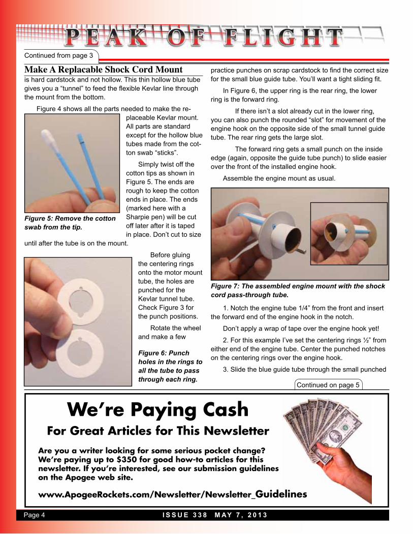
Figure 7: The assembled engine mount with the shock cord pass-through tube.
1. Notch the engine tube 1/4” from the front and insert the forward end of the engine hook in the notch.
Don’t apply a wrap of tape over the engine hook yet!
2. For this example I’ve set the centering rings ½” from either end of the engine tube. Center the punched notches on the centering rings over the engine hook.
3. Slide the blue guide tube through the small punched

Page 5I S S U E 3 3 8 M AY 7 , 2 0 1 3
Continued on page 6
Continued from page 4
Make A Replacable Shock Cord Mount
DON’T GLUE THE KEVLAR LOOP ONTO THE LOW-ER CENTERING RING! Don’t allow the loop to get glued down in a wet centering ring fillet. Install the loop after the centering ring fillets have dried.
The Kevlar loop should be tight enough around the mo-tor mount tube so it won’t slide down during boost.
The loose front end of the Kevlar is ready to be tied onto your choice of elastic shock cord.
holes in the centering rings. Leave the extra length beyond the ring ends for now.
4. Wrap a full turn of tape around the tube over the engine hook and blue guide tube “locking” both in place.
5. Apply glue fillets to the motor mount tube and center-ing ring joints. Let these fillets thoroughly dry before install-ing the Kevlar loop. Keep glue out of the hollow blue guide tube.
After the glue has dried, trim the excess blue guide tube off with a razor blade. Leave a little extra length out-side the flat face of the centering ring.
Before feeding the Kevlar through the blue guide tube, tie the loop of Kevlar around the end of the motor mount tube or a scrap piece of tube the same diameter. It should be tight around the tube but still loose enough that it could be slipped off later on. Tie a strong knot, You can apply a small drop of glue to the just the knot itself to make it permanent.
Leave a 1” long tail on the rear loose end of the Kevlar. When the mount is glued in place, the Kevlar will be trimmed off even with the end of the mainframe tube. You’ll want to leave a tail end that you can get to (and “wiggle” off the loop) with tweezers.
The loose end of the Kevlar is fed through the guide tube from the rear forward. Slide the tied loop over the en-gine hook and end of the tube and against the rear center-ing ring (see Figure 9 on the next page).
AltimeterOne
ww
w.A
pogeeRock
ets.co
mYour Source For Everything
Rock
etry
• Records peak speed and acceleration using 3-axis accelerometer.
• Also tells you how high the rocket flew.
“The one altimeter you’ll use in every rocket you fly.”
AltimeterOne - See how high your rocket flew
Penny shown for size comparisonwww.ApogeeRockets.com
AltimeterTwo - See how fast and high your rocket went
• Records peak altitude up to 29,000 feet (ASL). Displays in meters too!
• Easy-to-read LCD display. No need to count beeps or flashes of light.
Figure 8: Create a loop and tie a square knot on the shock cord.

Page 6 I S S U E 3 3 8 M AY 7 , 2 0 1 3
Continued from page 5
Make A Replacable Shock Cord Mount
Continued on page 7
The replaceable Kevlar mount is finished and ready to be glued into the main airframe tube.
After the mount is glued in place, cut off the excess Kevlar tail even with the end of the main body tube. This tail end gives you something to
Space Foundation certified as an excellent teaching aid. For further information, call Apogee Components at: 719-535-9335.
www.RockSim.comv9
Your Cool Rocket Designs Look So Much Better In
RockSim Version 9!
Design It.Launch It.
Figure 9: The bottom and top of the engine mount, with the Kevlar anchor installed. The inset shows the forward end of the mount.
Figure 11: The completed mount on a rocket with fins.
Figure 10: Leave a small tail so you can grab the loop easily when you want to inspect it.
grab onto when you want to check the condition of the Kev-lar or replace it if necessary. Simply grab the Kevlar tail with tweezers and work it off the end of the engine mount tube.
Figure 11 shows the replaceable mount inside the
Quest Aerospace One. It’s already been through a few flights. I can easily pull out the Kevlar line to check it’s condition.
This rear-tied replaceable Kevlar loop works best on engine mounts in BT-55 diameter and above airframe tubes.
It is possible to use this design in a BT-50 tube with a

Page 7I S S U E 3 3 8 M AY 7 , 2 0 1 3
Continued from page 6
Make A Replacable Shock Cord Mount This type of mount isn’t recommended or possible on mini-mum diameter BT-20 sized models.
In a future article I’ll explore some ideas on re-placeable Kevlar in BT-20 sized tubing. But you can see a technique called the “Lariat Loop” in Apogee’s Peak-of-Flight Newsletter #95 (www.ApogeeRockets.com/Educa-tion/Downloads/Newsletter95.pdf)
About the author:Chris Michielssen is an avid designer, builder and flyer
of low power model rockets. He produces Odd’l Rockets and accessories, available from Apogee Rockets.
His building blog: www.modelrocketbuilding.blogspot.com is followed by 650 people each day worldwide.
High-Power Reload Casings ww
w.A
pogeeRock
ets.co
m
• Reusable Rocket Motors Save Money• Holds Aerotech’s Reload Propellant• Sizes: 24mm To 98mm Diameter• Power Range: E Through N• Cases For Any Project• Rouse-Tech Quality• Affordable!
Your Source For Everything R
ocketry
FORWARD
Ties to Elastic Shock CordRearKevlar Loop
REAR VIEW
Feed slot filed or cut into 20/50 solid, round centering ring
SIDE VIEW
Figure 12: For smaller diameter rockets, you can cut or file a channel on the inside of the centering ring.
18mm engine mount with single, solid centering ring, such as shown in Figure 12.
A “tunnel” notch is cut or filed directly opposite the engine hook position. The continual long notch would guide a new Kevlar line through the mount from the rear.
The smaller the main airframe diameter, the harder it is to retrieve the end of the Kevlar tail for pulling and removal. Long thin tweezers can help grab the Kevlar tail.
Yes...We Have Engine
Mounts Too.