cobalt - d11fdyfhxcs9cr.cloudfront.net · cobalt tube marking guide a. hold the yellow kevlar cord...
TRANSCRIPT

1”
w w w . q u e s t a e r o s p a c e . c o m
Technique Tip
Step 11
Step 10
A. Apply a small line of wood glue to the root edge of the fin.B. Attach it to the body tube in correct position.C. Remove the fin and wipe away any excess glue on the fin and the body tube so there is only a very thin layer of glue left.D. Wait until the glue is dry, then re-apply a new line of glue to the root edge of the fin and re-attach the fin.
How to make a "Double Glue Joint" for extra fin strength
How to make a "Fin Fillet" for extra fin strength
Technique Tip
YES NO
A. After the Fin glue joints have completely dried, apply a thin bead of Wood Glue to both sides of a fin-body joint.
A. B.
B. Smooth out the glue with your finger. Wipe excess glue off your finger onto a tissue or paper towel.
PAGE 03
Step 09A. Carefully remove each of the Laser Cut Balsa Fins from the sheet with a sharp hobby knife.
B. Stack like fins together and sand all edges smooth.
Slide stack of Fins back and forth across sandpaper
A. Apply Wood Glue to the root edge of one Fin.B. Glue the Fin to the Body Tube along the Fin Line so it’s trailing edge is even with the end of the Body Tube.C. Check Alignment with drawing.D. Allow to dry.E. Repeat this step for the remaining Fins.
A. Apply Wood Glue to one side of the Launch Lug.B. Glue the Launch Lug the Body Tube along the Launch Lug Line.C. Check that so it's trailing edge is 1 inch from the end of the Body Tube.D. Allow to dry.
Step 07A. Cut out the Tube Marking Guide found on Page 02. Wrap the Tube Marking Guide over the White Body Tube and make a mark at each of the arrows with a pencil.
B. Use a door frame as a guide and extend each of the fin and launch lug pencil marks to about 3 inches from the end of the Body Tube. Draw a solid line for the fins, a dotted line for the Launch Lug.
Glue Bead
Step 08A. Apply a thick bead of Glue inside the Body Tube 1/2 inch from the end of the BodyTube. Thread the Shock Cord throughthe Body Tube, then using a twistingmotion, slide the completedMotor Mount Assembly intothe Body Tube so that theMotor Mount Tube isflush with theBody Tube.
B. Add another bead of Glue where the Centering Ring meets the Body Tube.
COBALTw w w . q u e s t a e r o s p a c e . c o m
PAGE 02
Step 01
Step 02
Step 03
Step 05
A. Insert the Motor Clip into the slit in the Yellow Motor Mount Tube.
B. Wrap a piece of tape all the way around the Yellow Motor Mount Tube to hold the Motor Clip in place.
A. Place the pre-slit Yellow Motor Mount Tube up against the ruler provided below. Make a pencil mark on the Tube 1/2 inch from the both ends.
A. Apply a bead of wood glue around inside edge of Yellow Motor Mount Tube as shown.
B. Insert the Blue Thrust Ring into the Yellow Motor Mount Tube so it is even with the end of the Yellow Motor Mount Tube.
Glue Bead
Knots Overhand Knot
A. Use two overhand knots to tie the Yellow Kevlar Cord around the Yellow Motor Mount Tube as shown.
Step 04
Cobalt TubeMarking guide
A. Hold the Yellow Kevlar Cord and the White Shock Cord side by side. Pull one end of each cord so that they are even with each other. While holding the two cords together, tie a single parallel overhand knot approximately one inch from the ends as shown.
B. Gently pull on both cords to set the knot and prevent it from slipping.
Yellow KevlarWhite Shock
Single Parallel Overhand Knot
Knot
NOTE THIS IS A VERY IMPORTANT STEP. IF YOU TIE A DIFFERENTTYPE OF KNOT THE SHOCK CORDS MAY SEPARATE DURING FLIGHT!
C. Apply a small amount of Wood Glue on the ends of both cords to prevent them from fraying.
Place Yellow Motor Mount Tube here. Place pencil marks on tube here.
COBALT
Visit our websitewww.questaerospace.com
Step 06
Glue Bead
Glue Bead
B. Slip the Centering Ring over the Yellow Motor Mount Tube so that it is aligned with Glue Bead on the pencil mark. Repeat for other Centering Ring.
A. Apply a bead of Glue along one pencil mark on the Yellow Motor Mount Tube. Thread the Shock Cord through one of the Centering Rings.
YES!
NO!

PAGE 01
Wood Glue
Alphatic Resin glues work best such as TITEBOND or ELMER'S CARPENTER'S WOOD GLUE
Spray Paint
Gloss Whiteand Royal Blue
Clear Tape
Scotch, 3M or similar
Masking Tape
Hobby Knife
Pencil
Things you'll need to assemble this kit
Prod No. 1021
40mm Tube 4” long, White Blowmold Nose Cone - WhiteLaser-cut Balsa Fin SheetYellow Motor Mount Tube w/slitMotor Mount ClipBlue Thrust Ring2” Launch LugDie-cut Centering RingSingle Hang Tab24“ Streamer18” Kevlar Cord18” White Elastic CordDecal Sheet Instruction SheetInstruction Sheet
1
1
1
1
1
1
1
2
1
1
1
1
1
1
1
A
B
C
D
E
F
G
H
I
J
K
L
M
N
P
A
B
H
F
C
G
D
E
J
M
K
L
I
115202080633028
10303S49000C
14000100011600728004281505005150011
1021-10301021-1010A1021-1010B
Parts for theCOBALT
BEFORE STARTING ASSEMBLY READ THROUGH THESE INSTRUCTIONS.IT IS BEST TO TEST FIT ALL PARTS BEFORE APPLYING ANY GLUE.
READ AND FOLLOW THE NAR MODEL ROCKET SAFETY CODE.
Manufactured by:
Quest Aerospace, Inc.
PO Box 2409
Pagosa Springs, CO 81147
1-800-858-7302
www.questaerospace.com
©2010-All Rights Reserved
1021-1010A
COBALTCOBALTw w w . q u e s t a e r o s p a c e . c o m
PAGE 04
Step 13A. Place a rolled up newspaper in the Motor Mount to act as a handle to hold while painting the rocket. Paint the entire rocket with White Enamel Spray Paint.
Step 14A. After the White Paint has thoroughly dried, use Masking Tape to mask off the White Fins. Place a strip on each White Fin, right up against the root edge. Then use newspaper to cover the rest of each White Fin.
B. Place a rolled up newspaper in the Motor Mount to act as a handle to hold while painting the rocket. Cover the entire rocket with Blue Enamel Spray Paint.
When paint is dry, carefully remove Masking Tape.
Step 12A. Peel the backing off the Gripper Tab and attach it to one end of the plastic Streamer.
B. Feed the loose end of the Shock Cord through the hole in the Gripper Tab.
C. Use two overhand knots to tie the loose end of the Shock Cord to the Nose Cone. Step 15
Place on other side of rocket opposite “COBALT” decal.
A.
A.
B.
E.
E.
C.
C.
D.
D. B.
The Decals in this kit are peel and stick, no wetting with water is required.
To allow more versatility in the placement of the Decals, cut them apart, peel off backing, then dip them in a shallow bowl of water with a drop of dish soap. The Decals can then be repositioned for a short time, then burnished down.
Place the decals in the appropriate positions shown.
COBALT
w w w . q u e s t a e r o s p a c e . c o m
PAGE 05
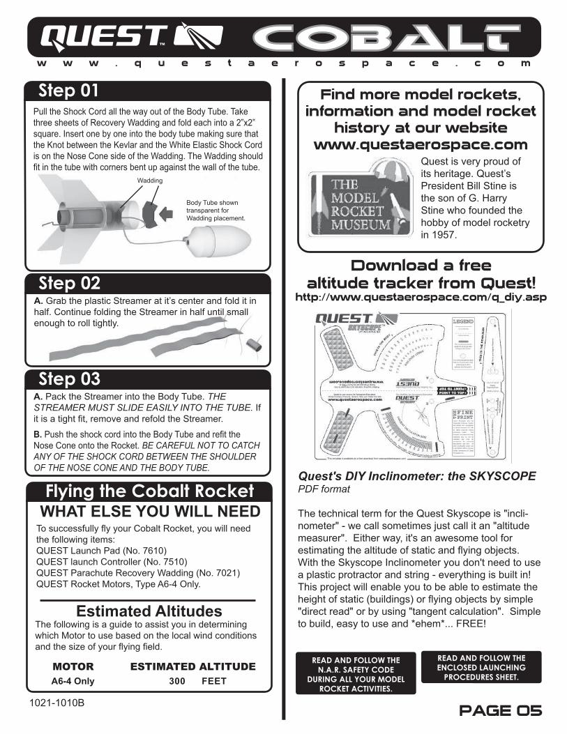
Flying the Cobalt RocketWHAT ELSE YOU WILL NEED
Estimated Altitudes
A6-4 Only 300 FEET
To successfully fly your Cobalt Rocket, you will need the following items:QUEST Launch Pad (No. 7610)QUEST launch Controller (No. 7510)QUEST Parachute Recovery Wadding (No. 7021)QUEST Rocket Motors, Type A6-4 Only.
The following is a guide to assist you in determining which Motor to use based on the local wind conditions and the size of your flying field.
MOTOR ESTIMATED ALTITUDEREAD AND FOLLOW THE ENCLOSED LAUNCHING
PROCEDURES SHEET.
READ AND FOLLOW THE N.A.R. SAFETY CODE
DURING ALL YOUR MODEL ROCKET ACTIVITIES.
COBALT
1021-1010B
Step 01Pull the Shock Cord all the way out of the Body Tube. Take three sheets of Recovery Wadding and fold each into a 2”x2” square. Insert one by one into the body tube making sure that the Knot between the Kevlar and the White Elastic Shock Cord is on the Nose Cone side of the Wadding. The Wadding should fit in the tube with corners bent up against the wall of the tube.
Step 02A. Grab the plastic Streamer at it’s center and fold it in half. Continue folding the Streamer in half until small enough to roll tightly.
Body Tube shown transparent for Wadding placement.
Wadding
Step 03A. Pack the Streamer into the Body Tube. THE STREAMER MUST SLIDE EASILY INTO THE TUBE. If it is a tight fit, remove and refold the Streamer.
B. Push the shock cord into the Body Tube and refit the Nose Cone onto the Rocket. BE CAREFUL NOT TO CATCH ANY OF THE SHOCK CORD BETWEEN THE SHOULDER OF THE NOSE CONE AND THE BODY TUBE.
Download a freealtitude tracker from Quest!
http://www.questaerospace.com/q_diy.asp
Quest's DIY Inclinometer: the SKYSCOPE PDF format The technical term for the Quest Skyscope is "incli-nometer" - we call sometimes just call it an "altitude measurer". Either way, it's an awesome tool for estimating the altitude of static and flying objects. With the Skyscope Inclinometer you don't need to use a plastic protractor and string - everything is built in! This project will enable you to be able to estimate the height of static (buildings) or flying objects by simple "direct read" or by using "tangent calculation". Simple to build, easy to use and *ehem*... FREE!
Find more model rockets,information and model rocket
history at our websitewww.questaerospace.com
Quest is very proud of its heritage. Quest’s President Bill Stine is the son of G. Harry Stine who founded the hobby of model rocketry in 1957.