in power module - phase adaptived
TRANSCRIPT

®SPECIF ICAT ION SUBMITTAL Page
Job Name:
Job Number:
Model Numbers:
myRoom DIN Power Module Low Capacity Phase Adaptive
369849h 1 11.29.18
DIN Power Module - Phase Adaptive The Phase Adaptive Power Module family is a group of
modular products for the control of lighting loads. This product is compatible with Lutron myRoom guestroom systems only.
Features• Leading-edge or trailing-edge dimming for
incandescent / halogen, electronic / magnetic low-voltage, and neon / cold cathode light sources.
• Controls dimmable CFL / LED loads. Refer to www.lutron.com/LEDTool for compatibility with dimmable CFL / LED light sources.
• RTISS Equipped technology compensates for incoming line-voltage variations (up to ± 2% change in frequency /second) such as changes in Root Mean Square (RMS) voltage, frequency shifts, harmonics, and line noise.
• NEMA® SSL7A-2015 compliant for compatibility with solid-state lighting.
• Includes QS link for seamless integration of lights, motorized window treatments, and control stations.
• Provides 4 Power Draw Units (PDUs) to power QS devices on the QS link.
• LEDs on the module provide diagnostic information.• Buttons on module provide load override control.• Power failure memory.
Models Available *
MQSE-4A1-D (shown)
CO
M
MU
X
MU
X
24 V-Zn. 1Prog. Zn. 2 Zn. 3 Zn. 4
N N N N DL1 DL2 DL3 DL4NL
100 - 120 V~ 220 - 240 V~ 50 / 60 Hz 4 A
220 - 240 V~ 50 / 60 Hz 4 A ε 1 A x 4, 1 AX x 4
myRoomMQSE-4A1-D
lutron.com
24 V- 132 mA
* Not all models are available in all countries.
Model Number Maximum Input Current Input Voltage OutputsMQSE-4A1-D 4 A 100–120 V~, 220–240 V~ 50/60 Hz 1 A per output, 4 outputsMQSE-3A1-D 3 A 120–240 V~ 50/60 Hz 1 A per output, 3 outputsMQSE-2A1-D 2 A 120–240 V~ 50/60 Hz 1 A per output, 2 outputs

®SPECIF ICAT ION SUBMITTAL Page
Job Name:
Job Number:
Model Numbers:
myRoom DIN Power Module Low Capacity Phase Adaptive
369849h 2 11.29.18
1 2 3 4
CC
I CO
M
CC
O N
.O.
CC
O C
OM
24 V-
CO
M
CC
I
CC
O N
.C.
MU
X
MU
XZn. 1Prog. Zn. 2 Zn. 3 Zn. 4
N N N NNL
24 V- 132 mA
1 AX, 1 FLA / 6 LRAM
1 A
myRoomMQSE-4S1-D
lutron.com
100 - 120 V~
220 - 240 V~ 50 / 60 Hz 4 A
220 - 240 V~ 50 / 60 Hz 4 A
CO
M
MU
X
MU
X
24 V-Zn. 1Prog. Zn. 2 Zn. 3 Zn. 4
N N N N DL1 DL2 DL3 DL4NL
100 - 120 V~ 220 - 240 V~ 50 / 60 Hz 4 A
220 - 240 V~ 50 / 60 Hz 4 A ε 1 A x 4, 1 AX x 4
myRoomMQSE-4A1-D
lutron.com
24 V- 132 mA
GCU-HOSPmyRoom
lutron.com
QS L1
1 2 3 4 5
COM
V+ MUX
DMUX
L1 TX / RX
PWRERR
L1L1
L1
FD/C
ol
Con/Act
RJ45
24 – 36 V- 250 mA
FD/C
ol
Con/Act
RJ45
PWR
2 1
CO
MP
5 4 3
L2 L1
2.0 A / L1, L224 – 36 V-
250 mA
L2 TX / RXL2
QS L2
1 2 3 4 5
COM
V+ MUX
DMUX
QS Link
Switching Power
Module
GCU-HOSP (for setup only)
To additional QS devices
Wireless Communication
QS Sensor Module (QSM) QS Power Supply (optional)
Radio Powr Savr Occupancy Sensor (up to 10 per QSM)
Pico Wireless Controller (up to 10 per QSM)
Multiple QS Sensor Modules can be added to increase the number of wireless inputs
and Pico wireless controllers.
System Example - myRoom Prime
3rd Party Magnetic Door Switch
CCI
CCO
Dimming Power Module
Room Thermostat (LR-HVAC-230-S) or3rd Party Thermostat
Palladiom Keypad
Palladiom Thermostat
QS Wired Shades and Draperies
®SPECIF ICAT ION SUBMITTAL Page
Job Name:
Job Number:
Model Numbers:
myRoom DIN Power Module Low Capacity Phase Adaptive
369849h 3 11.29.18
8 7 6 5 4 3 2 1PGM
CC
O 5
CC
O 4
CC
O 3
CC
O 2
CC
O 1
Sta
tus
4 3 2 1
CO
M
V+
MU
X
MU
X
QS
CC
O 1
NC
CC
O 1
NO
CC
O 2
NC
CC
O 2
NO
1-2
CO
M
CC
O 3
NC
CC
O 4
NO
CC
O 3
NO
CC
O 4
NC
3-4
CO
M
CC
O 5
NC
5 C
OM
CC
O 5
NO
CC
I 1
CC
I 2
CC
I 3
CC
I 4
CO
M
CC
I 5
V
RV0-36 V-0-36 V~ ½ A
R
1 A
ON
QSE-IO
lutron.com
24 – 36 V- 100 mA
GCU-HOSPmyRoom
lutron.com
QS L1
1 2 3 4 5
COM
V+ MUX
DMUX
L1 TX / RX
PWRERR
L1L1
L1
FD/C
ol
Con/Act
RJ45
24 – 36 V- 250 mA
FD/C
ol
Con/Act
RJ45
PWR
2 1
CO
MP
5 4 3
L2 L1
2.0 A / L1, L224 – 36 V-
250 mA
L2 TX / RXL2
QS L2
1 2 3 4 5
COM
V+ MUX
DMUX
CO
M
MU
X
MU
X
24 V-Zn. 1Prog. Zn. 2 Zn. 3 Zn. 4
N N N N DL1 DL2 DL3 DL4NL
100 - 120 V~ 220 - 240 V~ 50 / 60 Hz 4 A
220 - 240 V~ 50 / 60 Hz 4 A ε 1 A x 4, 1 AX x 4
myRoomMQSE-4A1-D
lutron.com
24 V- 132 mA
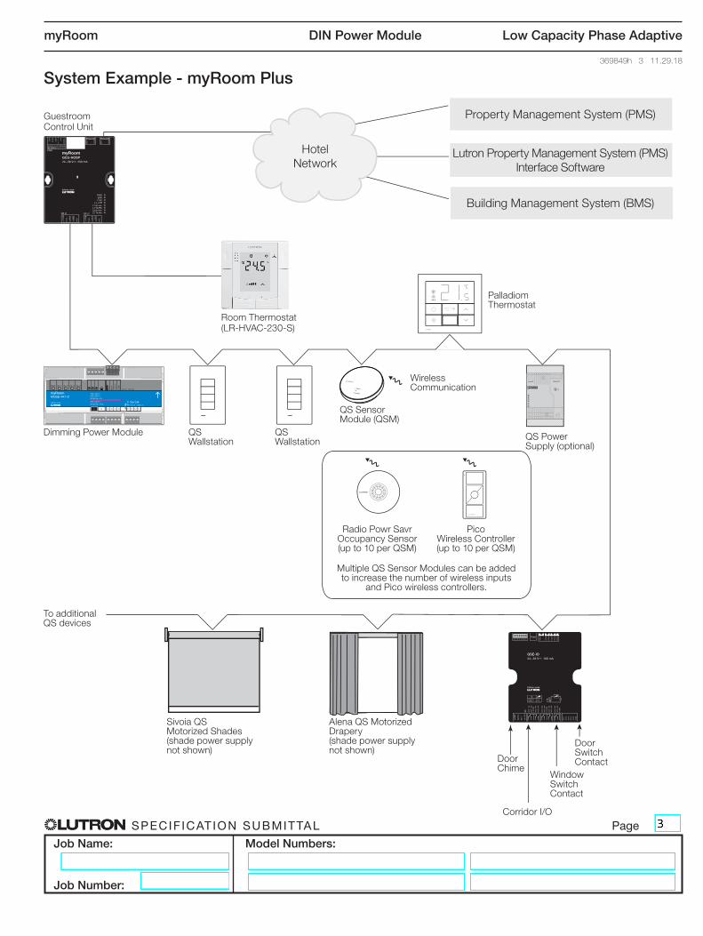
System Example - myRoom Plus
Guestroom Control Unit
Hotel Network
Property Management System (PMS)
Lutron Property Management System (PMS) Interface Software
Building Management System (BMS)
Room Thermostat(LR-HVAC-230-S)
Dimming Power Module QS Wallstation
Sivoia QS Motorized Shades (shade power supply not shown)
Alena QS Motorized Drapery (shade power supply not shown)
QS Wallstation
QS Sensor Module (QSM)
Door Chime
Window Switch Contact
Door Switch Contact
Corridor I/O
Palladiom Thermostat
Wireless Communication
Radio Powr Savr Occupancy Sensor (up to 10 per QSM)
Pico Wireless Controller (up to 10 per QSM)
Multiple QS Sensor Modules can be added to increase the number of wireless inputs
and Pico wireless controllers.
QS Power Supply (optional)
To additional QS devices
®SPECIF ICAT ION SUBMITTAL Page
Job Name:
Job Number:
Model Numbers:
myRoom DIN Power Module Low Capacity Phase Adaptive
369849h 4 11.29.18
Specifications
Regulatory Approvals• UL® Listed • cUL Listed• NOM Certified• RoHS Compliant• IEC / EN 60669 (220 –240 V~ 50/60 Hz only)• Lutron Quality Systems registered to ISO 9001.2015
Power• See Models Available table on page 1• Single input feed• Maximum Input Current: – MQSE-4A1-D = 4 A – MQSE-3A1-D = 3 A – MQSE-2A1-D = 2 A• Lightning strike protection meets ANSI / IEEE standard
C62.41 and IEC 61000-4-5. Can withstand voltage surges of up to 6 000 V~ and current surges of up to 3 000 A
• Standby power: <2 W (wired devices on QS link excluded)
• Provides 4 PDUs to power QS devices on QS link• ESD protection exceeds agency requirements per
IEC-61000-4-2• QS Link output: 24 V-
• For ungrounded delta feed applications, contact Lutron
Environment• For thermal specifications, see Output Zone Rating
and Mounting sections• Relative humidity: less than 90% non-condensing• For indoor use only
Terminals• Mains wiring: 1.0 mm² to 2.5 mm² (18 AWG to 12 AWG)
(single wire, solid or stranded)• Zone wiring: 1.0 mm² to 2.5 mm² (18 AWG to 12 AWG)
(single wire, solid or stranded)• QS Link: 0.5 mm² to 2.5 mm² (22 AWG to 12 AWG)
(single wire, solid or stranded)
Manual Mode Operation• By default, each zone is set to auto-detect the load
type and fade to only 100% (non-dim). See QS Dimming and Switching Power Module Installation Guide at www.lutron.com for details on programming the load type
• Zone buttons on the unit can be used to: – Turn loads on and off – Dim loads up and down when configured to a
dimmed load type

®SPECIF ICAT ION SUBMITTAL Page
Job Name:
Job Number:
Model Numbers:
myRoom DIN Power Module Low Capacity Phase Adaptive
369849h 5 11.29.18
Specifications (continued)
Output Zone Ratings• No Derating is required if all the conditions below are met:
– Calibration point maximum is 70 ºC (158 ºF) – Room ambient temperature is between 0 ºC and 30 ºC
(32 ºF and 86 ºF). – Panel ambient temperature, within 20 mm (0.80 in) of
unit, is between 0 ºC and 50 ºC (32 ºF and 122 ºF).• 25 W (100 – 120 V~) / 50 W (220 – 240 V~): Derating
on all zones is required for a single module in a non-ventilated enclosure if the room ambient temperature is between 30 ºC and 40 ºC (86 ºF and 104 ºF).
• 50 W (100 – 120 V~) / 100 W (220 – 240 V~): Derating on all zones is required in a multiple row non-ventilated enclosure if the temperature is between 30 ºC and 40 ºC (86 ºF and 104 ºF).
• Each zone has a 5 W (incandescent) minimum load requirement. For LED compatibility details, see www.lutron.com/LEDTool and Application Note #557 (P/N 048557) at www.lutron.com.
• When programmed to “auto” mode, the unit starts in reverse-phase and if an incompatible load is detected, it will convert to forward-phase.
• Does not support non-dimmable loads.• One load type per zone.• This module is designed to control loads with ratings
as noted in the table below. Outputs cannot be used to control general purpose receptacles.
A Refer to www.lutron.com/LEDtool for compatibility with dimmable CFL / LED light sources. B Only use iron core transformers intended for use with an electronic switch or dimmer per Clause 8.3 of IEC / EN 60669-2-1. C Actual lamp wattage.
Each zone is rated for the following wattage and load types A:
Load TypeZones 1 – 4
100 V~ 120 V~ 220 V~ 230 V~ 240 V~
Incandescent / Halogen 100 W 120 W 220 W 230 W 240 WElectronic Low-Voltage 100 W 120 W 220 W 230 W 240 WMagnetic Low-VoltageB 100 VA (75 W C) 120 VA (90 W C) 220 VA (165 W C) 230 VA (172 W C) 240 VA (180 W C)Neon / Cold CathodeB 100 VA (75 W C) 120 VA (90 W C) 220 VA (165 W C) 230 VA (172 W C) 240 VA (180 W C)Hi-lume A-Series LTE N/A 120 VA 1-6 drivers N/A N/A N/A
• Special considerations: – Outputs are not compatible with load-side switching
(i.e., breakers, switches, lamps with integral switch control, etc.)
– When controlling lamps, Lutron recommends using permanently installed fixtures. Output should not be used to control general purpose receptacles. Doing so will void the warranty.
– If controlling plug-in lamps, installation must ensure a method of preventing non-rated loads being plugged into the unit. An example is a dedicated receptacle with an alternate plug load such as a Duplex Dimming Receptacle (NTR-15-DDTR-) and Dimming Lamp Plug (RP-FDU-10-). Lamps must not be switched using the controls integral to the lamp.
– Controlling loads outside the parameters listed in the table below may damage the device and void the warranty.
• Run a separate neutral for each load circuit. A common neutral connection is not recommended.
• Unit may be powered by Ground Fault Interrupter (GFI) or Residual Current Circuit Breaker with Overload (RCBO) protected circuit if required. Load circuit wiring (from breaker to unit to load) must be run in its own non-metallic conduit, or nuisance tripping may occur.
• For applications requiring 0 –10 V- control, use 10 V- Interface (GRX-TVI).
• For applications requiring higher wattage ratings, use multiple individual circuits and group them into a single zone via software, or use a PHPM-PA for 120 V~ installations.
• Maximum wire length between Phase Adaptive Power Module and the load must be less than 30.5 m (100 ft).

®SPECIF ICAT ION SUBMITTAL Page
Job Name:
Job Number:
Model Numbers:
myRoom DIN Power Module Low Capacity Phase Adaptive
369849h 6 11.29.18
Mounting• Mount in IP20 (minimum) rated consumer panel or breaker
panel with integrated DIN rail.• For United States and Canada, use NEMA Type 1 minimum
rated enclosure.• Unit is 9 DIN modules (161.7 mm [6.37 in]) wide.• Mount in an accessible and serviceable location.• Unit may be mounted by pressing the unit onto the DIN rail
with the clips locked. To remove the unit from the DIN rail, unlock the clips using a screwdriver.
• Mount with arrows facing up to ensure adequate cooling.• See Lutron Application Note #466 (P/N 048466) at
www.lutron.com for more information on mounting and installation in panels with integrated DIN rail.
• Mount the Power Module where audible noise is acceptable (internal relay click).
• Unit generates heat, maximum 35 BTUs/Hour.• Mount unit such that all the conditions below are met: – Room ambient temperature is between 0 ºC and
40 ºC (32 ºF and 104 ºF). Zone derating applies for unventilated enclosures when ambient temperature is >30 ºC (86 ºF).
– Temperature inside mounting panel, within 20 mm (0.80 in) of unit, is between 0 ºC and 50 ºC (32 ºF and 122 ºF).
– Calibration point maximum: 70 ºC (158 ºF).
60.6 mm(2.38 in)
CO
M
MU
X
MU
X
24 V-Zn. 1Prog. Zn. 2 Zn. 3 Zn. 4
N N N N DL1 DL2 DL3 DL4NL
100 - 120 V~ 220 - 240 V~ 50 / 60 Hz 4 A
220 - 240 V~ 50 / 60 Hz 4 A ε 1 A x 4, 1 AX x 4
myRoomMQSE-4A1-D
lutron.com
24 V- 132 mA
89.7 mm(3.53 in)
161.7 mm(6.37 in)
Mechanical Dimensions
CO
M
MU
X
MU
X
24 V-Zn. 1Prog. Zn. 2 Zn. 3 Zn. 4
N N N N DL1 DL2 DL3 DL4NL
100 - 120 V~ 220 - 240 V~ 50 / 60 Hz 4 A
220 - 240 V~ 50 / 60 Hz 4 A ε 1 A x 4, 1 AX x 4
myRoomMQSE-4A1-D
lutron.com
24 V- 132 mACO
M
MU
X
MU
X
24 V-Zn. 1Prog. Zn. 2 Zn. 3 Zn. 4
N N N N DL1 DL2 DL3 DL4NL
100 - 120 V~ 220 - 240 V~ 50 / 60 Hz 4 A
220 - 240 V~ 50 / 60 Hz 4 A ε 1 A x 4, 1 AX x 4
myRoomMQSE-4A1-D
lutron.com
24 V- 132 mACO
M
MU
X
MU
X
24 V-Zn. 1Prog. Zn. 2 Zn. 3 Zn. 4
N N N N DL1 DL2 DL3 DL4NL
100 - 120 V~ 220 - 240 V~ 50 / 60 Hz 4 A
220 - 240 V~ 50 / 60 Hz 4 A ε 1 A x 4, 1 AX x 4
myRoomMQSE-4A1-D
lutron.com
24 V- 132 mACO
M
MU
X
MU
X
24 V-Zn. 1Prog. Zn. 2 Zn. 3 Zn. 4
N N N N DL1 DL2 DL3 DL4NL
100 - 120 V~ 220 - 240 V~ 50 / 60 Hz 4 A
220 - 240 V~ 50 / 60 Hz 4 A ε 1 A x 4, 1 AX x 4
myRoomMQSE-4A1-D
lutron.com
24 V- 132 mACO
M
MU
X
MU
X
24 V-Zn. 1Prog. Zn. 2 Zn. 3 Zn. 4
N N N N DL1 DL2 DL3 DL4NL
100 - 120 V~ 220 - 240 V~ 50 / 60 Hz 4 A
220 - 240 V~ 50 / 60 Hz 4 A ε 1 A x 4, 1 AX x 4
myRoomMQSE-4A1-D
lutron.com
24 V- 132 mA
Mounting clips (4) on unitLocked Unlocked

®SPECIF ICAT ION SUBMITTAL Page
Job Name:
Job Number:
Model Numbers:
myRoom DIN Power Module Low Capacity Phase Adaptive
369849h 7 11.29.18
Wiring from Distribution to Phase Adaptive Power Module• Turn off all circuit breakers or isolators feeding the Phase Adaptive Power Module at the distribution panel.• Run line / hot and neutral wires from a 100 –120 / 220 –240 V~ 50 / 60 Hz feed to the Phase Adaptive Power
Module unit.• Run a separate neutral for each load circuit. A common neutral connection is not recommended.• All loads should be fully wired and tested for short circuits BEFORE connecting to the module.
Mains Wiring and IEC PELV / NEC® Class 2 Separation• Follow appropriate local and national codes to avoid violating required separation guidelines.
Wiring: Mains and Output Zones
CO
M
MU
X
MU
X
24 V-Zn. 1Prog. Zn. 2 Zn. 3 Zn. 4
N N N N DL1 DL2 DL3 DL4NL
100 - 120 V~ 220 - 240 V~ 50 / 60 Hz 4 A
220 - 240 V~ 50 / 60 Hz 4 A ε 1 A x 4, 1 AX x 4
myRoomMQSE-4A1-D
lutron.com
24 V- 132 mA
Zone 1
Zone 2
Zone 3
Zone 4
CO
M
MU
X
MU
X
24 V-Zn. 1Prog. Zn. 2 Zn. 3 Zn. 4
N N N N DL1 DL2 DL3 DL4NL
100 - 120 V~ 220 - 240 V~ 50 / 60 Hz 4 A
220 - 240 V~ 50 / 60 Hz 4 A ε 1 A x 4, 1 AX x 4
myRoomMQSE-4A1-D
lutron.com
24 V- 132 mA
Mains Neutral Outputs
CO
M
MU
X
MU
X
24 V-Zn. 1Prog. Zn. 2 Zn. 3 Zn. 4
N N N N DL1 DL2 DL3 DL4NL
100 - 120 V~ 220 - 240 V~ 50 / 60 Hz 4 A
220 - 240 V~ 50 / 60 Hz 4 A ε 1 A x 4, 1 AX x 4
myRoomMQSE-4A1-D
lutron.com
24 V- 132 mA
Distribution Panel100 – 120 /
220 – 240 V~
Line/Hot
Neutral
To additional modules
Note: If feeding through Lutron modules using mains terminals, total current of all modules must be less than or equal to 15 A.
IEC PELV/NEC® Class 2QS Link
CO
M
MU
X
MU
X
24 V-Zn. 1Prog. Zn. 2 Zn. 3 Zn. 4
N N N N DL1 DL2 DL3 DL4NL
100 - 120 V~ 220 - 240 V~ 50 / 60 Hz 4 A
220 - 240 V~ 50 / 60 Hz 4 A ε 1 A x 4, 1 AX x 4
myRoomMQSE-4A1-D
lutron.com
24 V- 132 mAEarth

®SPECIF ICAT ION SUBMITTAL Page
Job Name:
Job Number:
Model Numbers:
myRoom DIN Power Module Low Capacity Phase Adaptive
369849h 8 11.29.18
Wiring: QS Link
IEC PELV/NEC® Class 2 QS Link Wiring• Link communicates using IEC PELV / NEC®
Class 2 wiring.• Follow all applicable national and local codes for
proper circuit separation and protection.• Turn off all breakers or isolators feeding the Phase
Adaptive Power Module before servicing.• Wiring may be t-tapped or daisy-chained.• Total length of QS link must not exceed 610 m
(2 000 ft). – For the Lutron All-In-One cable specification, see
Lutron P / N 369596 or 369597 at www.lutron.com.• Control power link (COM, 24 V-) wiring: – For lengths under 150 m (500 ft), use 1.0 mm2
(18 AWG) conductors. – For lengths over 150 m (500 ft), use 2.5 mm2
(12 AWG) conductors.• Data link (MUX, MUX) wiring: – Use one, twisted-shielded pair of 1.0 mm2
(18 AWG). – Alternate data-only cable: use approved data link
cable (0.5 mm2 [22 AWG] twisted, shielded) from Belden, model #9461.
• Each QS link IEC PELV/NEC® Class 2 terminal will accept up to two 1.0 mm2 (18 AWG) wires; two 2.5 mm2 (12 AWG) wires will not fit. If using two 2.5 mm2 (12 AWG) wires, connect using appropriate wire connectors.
Note: For more information on PDUs, refer to the Power Draw Units on the QS Link document (P/N 369405) at www.lutron.com
CO
M
MU
X
MU
X
24 V-Zn. 1Prog. Zn. 2 Zn. 3 Zn. 4
N N N N DL1 DL2 DL3 DL4NL
100 - 120 V~ 220 - 240 V~ 50 / 60 Hz 4 A
220 - 240 V~ 50 / 60 Hz 4 A ε 1 A x 4, 1 AX x 4
myRoomMQSE-4A1-D
lutron.com
24 V- 132 mACO
M
MU
X
MU
X
24 V-Zn. 1Prog. Zn. 2 Zn. 3 Zn. 4
N N N N DL1 DL2 DL3 DL4NL
100 - 120 V~ 220 - 240 V~ 50 / 60 Hz 4 A
220 - 240 V~ 50 / 60 Hz 4 A ε 1 A x 4, 1 AX x 4
myRoomMQSE-4A1-D
lutron.com
24 V- 132 mA
CO
M
MU
X
MU
X
24 V-Zn. 1Prog. Zn. 2 Zn. 3 Zn. 4
N N N N DL1 DL2 DL3 DL4NL
100 - 120 V~ 220 - 240 V~ 50 / 60 Hz 4 A
220 - 240 V~ 50 / 60 Hz 4 A ε 1 A x 4, 1 AX x 4
myRoomMQSE-4A1-D
lutron.com
24 V- 132 mA
Control Link
Data Link
1: COM
2: 24 V-
3: MUX
4: MUX
)Lutron, Lutron, RTISS Equipped, Palladiom, Pico, Alena, Sivoia, and Hi-lume are trademarks of Lutron Electronics Co., Inc., registered in the U.S. and other countries.myRoom and Radio Powr Savr are trademarks of Lutron Electronics Co., Inc.
UL is a trademark of UL LLC.
NEC is a registered trademark of National Fire Protection Association, Quincy, Massachusetts.
NEMA is the registered trademark and service mark of the National Electrical Manufacturers Association.