i.mxrt1010 product lifetime usage estimates
TRANSCRIPT
1 IntroductionThis document describes the estimated product lifetimes for the i.MX RT1010applications processors based on the criteria used in the qualification process.
The product lifetimes described here are estimates and do not represent aguaranteed lifetime of the processor.
The i.MX RT series consist of an extensive number of processors thatdeliver a wide range of processing and multimedia capabilities across variousqualification levels.
This document guides on how to interpret different i.MX RT1010 qualificationlevels in terms of the target operating frequency of the device, the maximumsupported junction temperature (Tj) of the processor, and how this relates tothe lifetime of the device.
Each qualification level supported, commercial and industrial, defines a number of Power-on Hours (PoH) available to theprocessor under a given set of conditions, such as:
• The target frequency for the application, commercial and industrial.
— The target frequency is determined by the input voltage to the processor’s core complex (VDD_SOC_IN).
— The use of the DCDC-enabled or DCDC-bypass modes.
— When using the DCDC-bypass mode, the target voltage should not be set to the minimum specified in the datasheet.All power management ICs have allowable tolerances. The target voltage must be set higher than the minimumspecified voltage to account for the tolerance of the PMIC. The tolerance assumed in the calculations in thisdocument is +/25 mV.
— The DCDC-enabled mode uses the DCDC module to create a power supply for the core logic on the i.MX RT series.The DCDC module is well characterized and can be set to output the exact minimum specified voltage. LongerPower-on-Hours can be achieved using the DCDC-enabled mode.
• The percentage of active use compared to standby.
— Active use means that the processor is running in an active performance mode.
— For the commercial tiers, there are two performance modes available: 500 MHz and 400 MHz.
— In the DSM mode, the datasheet defines lower operating conditions for VDD_SOC_IN, reducing the powerconsumption and junction temperature. In this mode, the voltage and temperature are set low enough so that theeffect on the lifetime calculations is negligible and treated as if the device was powered off.
• The junction temperature (Tj) of the processor.
— The maximum junction temperature of the device is different for each tier of the product. For example, 95 ℃ forcommercial and 105 ℃ for industrial. This maximum temperature is guaranteed by the final test.
Ensure that your device is appropriately thermally managed and the maximum junction temperature is not exceeded.
Contents
1 Introduction......................................12 Device qualification level and
available PoH.................................. 22.1 Commercial qualification..............22.2 Industrial qualification.................. 43 Combining use cases......................63.1 Scenario 1: Switching between two
power states with differentvoltages........................................6
3.2 Scenario 2: Switching between twopower states with differenttemperatures................................7
3.3 Scenario 3: Using three or morepower states.................................8
AN13025i.MXRT1010 Product Lifetime Usage EstimatesRev. 0 — 10/2020 Application Note
All data provided within this document are estimates for the PoH that are based on extensive qualificationexperience and testing with the i.MX RT series. These statistically derived estimates must not be viewed as a limiton an individual device’s lifetime, nor construed as a guarantee by NXP as to the actual lifetime of the device. Thesales and warranty terms and conditions still apply.
NOTE
2 Device qualification level and available PoH
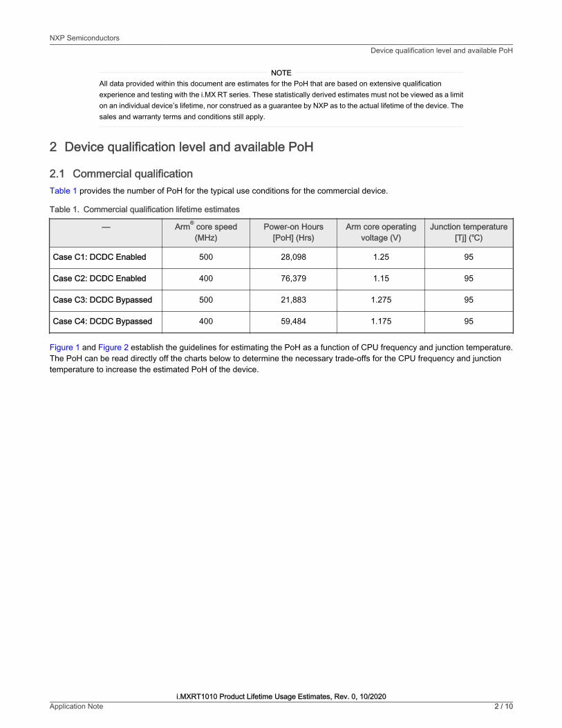
2.1 Commercial qualificationTable 1 provides the number of PoH for the typical use conditions for the commercial device.
Table 1. Commercial qualification lifetime estimates
— Arm® core speed(MHz)
Power-on Hours[PoH] (Hrs)
Arm core operatingvoltage (V)
Junction temperature[Tj] (℃)
Case C1: DCDC Enabled 500 28,098 1.25 95
Case C2: DCDC Enabled 400 76,379 1.15 95
Case C3: DCDC Bypassed 500 21,883 1.275 95
Case C4: DCDC Bypassed 400 59,484 1.175 95
Figure 1 and Figure 2 establish the guidelines for estimating the PoH as a function of CPU frequency and junction temperature.The PoH can be read directly off the charts below to determine the necessary trade-offs for the CPU frequency and junctiontemperature to increase the estimated PoH of the device.
NXP SemiconductorsDevice qualification level and available PoH
i.MXRT1010 Product Lifetime Usage Estimates, Rev. 0, 10/2020Application Note 2 / 10

Figure 1. i.MXRT1010 commercial lifetime estimates, DCDC-enabled mode
NXP SemiconductorsDevice qualification level and available PoH
i.MXRT1010 Product Lifetime Usage Estimates, Rev. 0, 10/2020Application Note 3 / 10

Figure 2. i.MXRT1010 commercial lifetime estimates, DCDC-bypass mode
2.2 Industrial qualificationTable 2 provides the number of PoH for the typical use conditions for the industrial device.
Table 2. Industrial qualification lifetime estimates
— Arm core speed (MHz) Power-on Hours [PoH](Hrs)
Arm core operatingvoltage (V)
Junction temperature[Tj] (℃)
Case I1: DCDC enabled 400 88,407 1.15 105
Case I2:DCDC bypassed
400 68,851 1.175 105
Figure 3 and Figure 4 establish the guidelines for estimating the PoH as a function of CPU frequency and junction temperature.The PoH can be read directly off the charts below to determine the necessary trade-offs for the CPU frequency and junctiontemperature to increase the estimated PoH of the device.
NXP SemiconductorsDevice qualification level and available PoH
i.MXRT1010 Product Lifetime Usage Estimates, Rev. 0, 10/2020Application Note 4 / 10

Figure 3. i.MXRT1010 Industrial lifetime estimates DCDC-enabled mode
NXP SemiconductorsDevice qualification level and available PoH
i.MXRT1010 Product Lifetime Usage Estimates, Rev. 0, 10/2020Application Note 5 / 10

Figure 4. i.MXRT1010 Industrial lifetime estimates DCDC-bypass mode
3 Combining use casesIn some applications, a constant operating use case cannot deliver the target PoH. In this case, it is better to use multiple operatingconditions. This method provides some of the lifetime benefits of running at a lower performance use case, while keeping the abilityof the system to use the highest performance state dictated by the application’s demands.
3.1 Scenario 1: Switching between two power states with different voltagesIn this scenario, the system is using the 500 MHz full-power state, and the 400 MHz reduced-power state. For these calculations,it is assumed that the temperature stays constant in either mode. If thesystem spends 50 % of its power-on-time at 500 MHz and50 % of its power-on-time at 400 MHz, the two POH, as shown in Figure 5, can be combined with using those percentages: 31,698× 0.5 + 86,165 × 0.5 = 58,931 PoH.
NXP SemiconductorsCombining use cases
i.MXRT1010 Product Lifetime Usage Estimates, Rev. 0, 10/2020Application Note 6 / 10

Figure 5. Multiple power state use case
3.2 Scenario 2: Switching between two power states with different temperaturesThis scenario assumes that the system can achieve a drop-in temperature by throttling back the performance while stillmaintaining a constant voltage. This temperature change can be achieved by changing the frequency or by simply scaling backthe load on the Arm cores (or processing units). This use case is particularly useful for users who need to take advantage of thefull commercial temperature range of the i.MX RT MCUs. In this scenario, the system spends 30 % of its PoH at 93 °C and 70 %of its power-on hours at 85 °C, as shown in Figure 6. The two PoHs can be combined as follows: 31,698 × 0.3 + 52,038 × 0.7 =45,932 PoH.
NXP SemiconductorsCombining use cases
i.MXRT1010 Product Lifetime Usage Estimates, Rev. 0, 10/2020Application Note 7 / 10

Figure 6. Multiple temperature use case
3.3 Scenario 3: Using three or more power statesThis scenario shows how to extend this strategy to more than two power states. While this example has only three power states,there is no limit to the actual number of the power states that can be combined. The power states that are being used in thisscenario are 400 MHz (at 93 °C) and 500 MHz (at 85 °C and 93 °C). Each state is used one third of the time. These power statescan be combined as follows: 86,165 × 0.34 + 52,038 × 0.33 + 31,298 × 0.33 = 56,796 PoH.
NXP SemiconductorsCombining use cases
i.MXRT1010 Product Lifetime Usage Estimates, Rev. 0, 10/2020Application Note 8 / 10

Figure 7. Various use cases
NXP SemiconductorsCombining use cases
i.MXRT1010 Product Lifetime Usage Estimates, Rev. 0, 10/2020Application Note 9 / 10

How To Reach Us
Home Page:
nxp.com
Web Support:
nxp.com/support
Information in this document is provided solely to enable system and software implementersto use NXP products. There are no express or implied copyright licenses granted hereunderto design or fabricate any integrated circuits based on the information in this document. NXPreserves the right to make changes without further notice to any products herein.
NXP makes no warranty, representation, or guarantee regarding the suitability of its productsfor any particular purpose, nor does NXP assume any liability arising out of the applicationor use of any product or circuit, and specifically disclaims any and all liability, includingwithout limitation consequential or incidental damages. “Typical” parameters that may beprovided in NXP data sheets and/or specifications can and do vary in different applications,and actual performance may vary over time. All operating parameters, including “typicals,”must be validated for each customer application by customer's technical experts. NXP doesnot convey any license under its patent rights nor the rights of others. NXP sells productspursuant to standard terms and conditions of sale, which can be found at the following address:nxp.com/SalesTermsandConditions.
While NXP has implemented advanced security features, all products may be subject tounidentified vulnerabilities. Customers are responsible for the design and operation of theirapplications and products to reduce the effect of these vulnerabilities on customer’s applicationsand products, and NXP accepts no liability for any vulnerability that is discovered. Customersshould implement appropriate design and operating safeguards to minimize the risks associatedwith their applications and products.
NXP, the NXP logo, NXP SECURE CONNECTIONS FOR A SMARTER WORLD, COOLFLUX,EMBRACE, GREENCHIP, HITAG, ICODE, JCOP, LIFE VIBES, MIFARE, MIFARE CLASSIC,MIFARE DESFire, MIFARE PLUS, MIFARE FLEX, MANTIS, MIFARE ULTRALIGHT,MIFARE4MOBILE, MIGLO, NTAG, ROADLINK, SMARTLX, SMARTMX, STARPLUG, TOPFET,TRENCHMOS, UCODE, Freescale, the Freescale logo, AltiVec, CodeWarrior, ColdFire,ColdFire+, the Energy Efficient Solutions logo, Kinetis, Layerscape, MagniV, mobileGT, PEG,PowerQUICC, Processor Expert, QorIQ, QorIQ Qonverge, SafeAssure, the SafeAssure logo,StarCore, Symphony, VortiQa, Vybrid, Airfast, BeeKit, BeeStack, CoreNet, Flexis, MXC, Platformin a Package, QUICC Engine, Tower, TurboLink, EdgeScale, EdgeLock, eIQ, and Immersive3Dare trademarks of NXP B.V. All other product or service names are the property of theirrespective owners. AMBA, Arm, Arm7, Arm7TDMI, Arm9, Arm11, Artisan, big.LITTLE, Cordio,CoreLink, CoreSight, Cortex, DesignStart, DynamIQ, Jazelle, Keil, Mali, Mbed, Mbed Enabled,NEON, POP, RealView, SecurCore, Socrates, Thumb, TrustZone, ULINK, ULINK2, ULINK-ME,ULINK-PLUS, ULINKpro, µVision, Versatile are trademarks or registered trademarks of ArmLimited (or its subsidiaries) in the US and/or elsewhere. The related technology may be protectedby any or all of patents, copyrights, designs and trade secrets. All rights reserved. Oracleand Java are registered trademarks of Oracle and/or its affiliates. The Power Architecture andPower.org word marks and the Power and Power.org logos and related marks are trademarksand service marks licensed by Power.org.
© NXP B.V. 2020. All rights reserved.
For more information, please visit: http://www.nxp.comFor sales office addresses, please send an email to: [email protected]
Date of release: 10/2020Document identifier: AN13025