im 7600-cln 1 0599 b - abb ltd · 7600 series abb instrumentation. ... information in this manual...
TRANSCRIPT

Operating Instructions
Ultrasonic & MechanicalElectrode Cleaning Systems
Models:7651, 7654, 7655, 7656,7660, 7661, 7664, 7665
7600 Series
ABB Instrumentation

ABB INSTRUMENTATION
✶ Note.Clarification of an instruction or additional information.
Information.Further reference for more detailed information ortechnical details.
Although Warning hazards are related to personal injury, and Caution hazards are associated with equipment or property damage,it must be understood that operation of damaged equipment could, under certain operational conditions, result in degradedprocess system performance leading to personal injury or death. Therefore, comply fully with all Warning and Caution notices.
Information in this manual is intended only to assist our customers in the efficient operation of our equipment. Use of this manualfor any other purpose is specifically prohibited and its contents are not to be reproduced in full or part without prior approval ofTechnical Communications Department, ABB Instrumentation.
The Company
ABB Instrumentation is an established world force in the design and manufacture ofinstrumentation for industrial process control, flow measurement, gas and liquid analysis andenvironmental applications.
As a part of ABB, a world leader in process automation technology, we offer customersapplication expertise, service and support worldwide.
We are committed to teamwork, high quality manufacturing, advanced technology andunrivalled service and support.
The quality, accuracy and performance of the Company’s products result from over 100 yearsexperience, combined with a continuous program of innovative design and development toincorporate the latest technology.
The NAMAS Calibration Laboratory No. 0255(B) is just one of the ten flow calibration plantsoperated by the Company, and is indicative of ABB Instrumentation’s dedication to qualityand accuracy.
RE
GIS T E R E D F
IRM
BS EN ISO 9001
St Neots, U.K. – Cert. No. Q5907Stonehouse, U.K. – Cert. No. FM 21106
Stonehouse, U.K. – Cert. No. 0255
EN 29001 (ISO 9001)
Lenno, Italy – Cert. No. 9/90A
Use of Instructions
Warning.An instruction that draws attention to the risk of injury ordeath.
Caution.An instruction that draws attention to the risk of damage tothe product, process or surroundings.
Health and SafetyTo ensure that our products are safe and without risk to health, the following points must be noted:
1. The relevant sections of these instructions must be read carefully before proceeding.
2. Warning labels on containers and packages must be observed.
3. Installation, operation, maintenance and servicing must only be carried out by suitably trained personnel and in accordance with theinformation given.
4. Normal safety precautions must be taken to avoid the possibility of an accident occurring when operating in conditions of high pressureand/or temperature.
5. Chemicals must be stored away from heat, protected from temperature extremes and powders kept dry. Normal safe handling proceduresmust be used.
6. When disposing of chemicals ensure that no two chemicals are mixed.
Safety advice concerning the use of the equipment described in this manual or any relevant hazard data sheets (where applicable) may beobtained from the Company address on the back cover, together with servicing and spares information.

1
SECTION A – MODEL 7650 020 FLOW POWERED CLEANING SYSTEM
CONTENTS
Section Page Section Page
INTRODUCTION ............................................................ 2
A1 DESCRIPTION ............................................................ 3
A2 LOCATION ............................................................ 3
A3 INSTALLATION ........................................................... 4A3.1 Existing Installation ........................................... 4A3.2 New Installation ................................................ 4
A4 OPERATION 4A4.1 Setting-up ......................................................... 4A4.2 Routine 4
A5 MAINTENANCE .......................................................... 5A5.1 Examination of FPD .......................................... 5A5.2 Replacement of FPD ........................................ 5
A6 SPARE PARTS ............................................................ 5
A7 SPECIFICATION ......................................................... 5
B1 INTRODUCTION ......................................................... 6
B2 DESCRIPTION7B2.1 Transducer Element ......................................... 7B2.2 Generator Unit .................................................. 7B2.3 Glass Electrodes .............................................. 8
B3 INSTALLATION ........................................................... 8B3.1 Mounting the Generator Unit ............................ 8B3.2 Fitting the Transducer ....................................... 8
B3.2.1 Models 7651/7660 ‘flow’ Systems ....... 9B3.2.2 Models 7654 , 7655 or 7656
‘dip’ Systems ....................................... 9B3.3 Electrical Connections .................................... 10
B4 SETTING-UP .......................................................... 11
B5 ROUTINE MAINTENANCE ....................................... 12B5.1 Changing the Sensors .................................... 12
B6 SPARE PARTS .......................................................... 12
B7 SPECIFICATION ........................................................ 13
SECTION B – ULTRASONIC CLEANINGSYSTEM
SECTION C – MECHANICAL WIPERCLEANING SYSTEM
C1 INTRODUCTION ....................................................... 14
C2 DESCRIPTION .......................................................... 15C2.1 Principle of Operation ..................................... 15C2.2 Model 7610 Control Unit ................................. 15
C3 INSTALLATION ......................................................... 16C3.1 Mounting the Control Unit ............................... 16C3.2 Fitting the Wiper Mechanism .......................... 16C3.3 Pneumatic Connections .................................. 18C3.4 Electrical Connections .................................... 20
C4 SETTING-UP .......................................................... 20
C5 MAINTENANCE ......................................................... 21C5.1 Changing the Wiper Assembly ....................... 21C5.2 Changing the Sensor ...................................... 21C5.3 Fuses .......................................................... 21
C6 SPARE PARTS .......................................................... 22
C7 SPECIFICATION ........................................................ 22

2
INTRODUCTION
This manual gives the information required by users of thevarious types of Kent-Taylor electrode cleaning systems.
The systems are as follows:
• Model 7650 020 Flow Powered Cleaning System• Model 7612/13 Ultrasonic Cleaning System• Model 7610/11 Mechanical Wiper Cleaning System
The 7650 020 system uses a flow powered device for directmechanical cleaning of the sensor tip. The 7612/13 systemuses ultrasonic pressure waves for indirect cleaning of thesensor. The 7610/11 system uses an air powered wiper fordirect mechanical cleaning of the sensor tip.
The cleaning systems are supplied for fitting to certain modelsof the Kent-Taylor 7650/60 series of industrial electrodesystems as indicated in Tables A1.1, B1.1 and C1.1. Forinformation on the various Kent-Taylor industrial electrodesystems refer to the operating manual for the 7650/60 seriesof Electrode Systems.
For information on a particular cleaning system model refer tothe appropriate section of this manual. Information is given forthe separate supply of system items for new or existingelectrode system installations. When a cleaning system isfitted into an electrode system, it is not normally necessaryto remove any of the cleaning system components whenremoving the sensors.
Although information relates to the current series of industrialelectrode systems, the information on the 7612/ 13 ultrasonicand 7610/ 11 wiper cleaning systems themselves is also validfor the earlier 7600 series of industrial electrode systems.There are installation differences within the electrode systemson the earlier series. These differences can be established byreference to the operating manual for the original electrodesystem.
General Notes:
a) The term ‘high purity water’ is used throughout this manualto mean distilled or double de-ionised water with abackground impurity level of less than 0.01mgl–1 (ppm).
b) Where parts for fitting are mentioned in the text, it may beassumed that they are of new supply with the cleaningsystems, unless specifically mentioned as being retainedfrom existing equipment.
c) Where appropriate, Kent-Taylor part numbers are given inthe text thus: (XXXX XXX)
c) Where an instruction is given to ‘discard’ an item, thismeans that the item is not required in the modified system.The actual disposal policy for the redundant item is a userdecision.
3
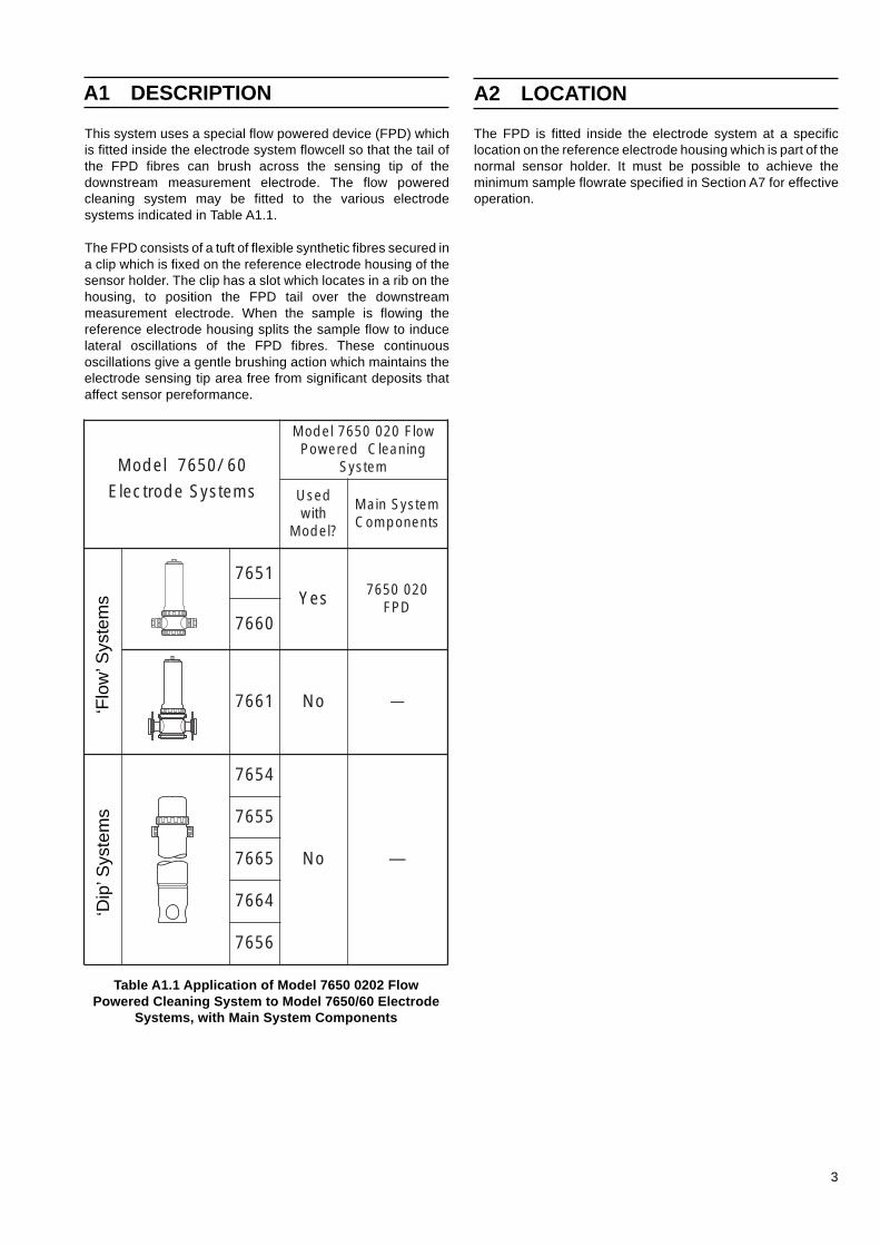
This system uses a special flow powered device (FPD) whichis fitted inside the electrode system flowcell so that the tail ofthe FPD fibres can brush across the sensing tip of thedownstream measurement electrode. The flow poweredcleaning system may be fitted to the various electrodesystems indicated in Table A1.1.
The FPD consists of a tuft of flexible synthetic fibres secured ina clip which is fixed on the reference electrode housing of thesensor holder. The clip has a slot which locates in a rib on thehousing, to position the FPD tail over the downstreammeasurement electrode. When the sample is flowing thereference electrode housing splits the sample flow to inducelateral oscillations of the FPD fibres. These continuousoscillations give a gentle brushing action which maintains theelectrode sensing tip area free from significant deposits thataffect sensor pereformance.
‘Flo
w’ S
yste
ms
‘Dip
’ Sys
tem
sA1 DESCRIPTION
The FPD is fitted inside the electrode system at a specificlocation on the reference electrode housing which is part of thenormal sensor holder. It must be possible to achieve theminimum sample flowrate specified in Section A7 for effectiveoperation.
A2 LOCATION
Table A1.1 Application of Model 7650 0202 FlowPowered Cleaning System to Model 7650/60 Electrode
Systems, with Main System Components
06/0567ledoM
wolF0200567ledoMgninaelCderewoP
metsyS
smetsySedortcelE desUhtiw
?ledoM
metsySniaMstnenopmoC
1567seY 0200567
DPF0667
1667 oN —
4567
oN —
5567
5667
4667
6567
4
A4.1 Setting-upThere are no setting-up requirements for the system, otherthan ensuring that the sample flowrate conforms to therequirements given in Section A7.
A4.2 RoutineThere are no routine activities for checking the operation of thesystem other than using instrument readings as an indirectcheck.
A3 INSTALLATION
A3.1 Existing InstallationTo fit the flow powered cleaning system to an existing ‘flow’electrode system installation, carry out the procedure asfollows:
Warning. Always ensure in the case of in-linesystems that the sample line pressure is reduced to zerobefore removing the electrode assembly from thesampling point.
Caution. Complete this procedure within 2 hours,or take steps to avoid drying out and degradation ofelectrodes.
a) Isolate the sample line.
b) Release the clamp ring securing the top cover and lift offthe cover with the sensor holder.
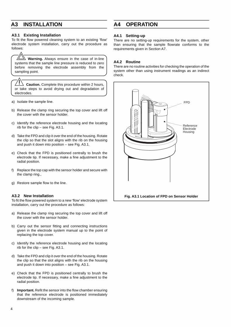
c) Identify the reference electrode housing and the locatingrib for the clip – see Fig. A3.1.
d) Take the FPD and clip it over the end of the housing. Rotatethe clip so that the slot aligns with the rib on the housingand push it down into position – see Fig. A3.1.
e) Check that the FPD is positioned centrally to brush theelectrode tip. If necessary, make a fine adjustment to theradial position.
f) Replace the top cap with the sensor holder and secure withthe clamp ring.,
g) Restore sample flow to the line.
A3.2 New InstallationTo fit the flow powered system to a new ‘flow’ electrode systeminstallation, carry out the procedure as follows:
a) Release the clamp ring securing the top cover and lift offthe cover with the sensor holder.
b) Carry out the sensor fitting and connecting instructionsgiven in the electrode system manual up to the point ofreplacing the top cover.
c) Identify the reference electrode housing and the locatingrib for the clip – see Fig. A3.1.
d) Take the FPD and clip it over the end of the housing. Rotatethe clip so that the slot aligns with the rib on the housingand push it down into position – see Fig. A3.1.
e) Check that the FPD is positioned centrally to brush theelectrode tip. If necessary, make a fine adjustment to theradial position.
f) Important. Refit the sensor into the flow chamber ensuringthat the reference electrode is positioned immediatelydownstream of the incoming sample.
A4 OPERATION
Fig. A3.1 Location of FPD on Sensor Holder
FPD
ReferenceElectrodeHousing

5
A5 MAINTENANCE
The following spare parts are available for the flow poweredcleaning system direct from ABB Kent-Taylor, Oldends Lane,Stonehouse, Gloucs., GL10 3TA, England or through ourworldwide organisation :
Item Kent-Taylor Part No.Flow Powered Device (FPD) 7650 020
✶ Note. Individual items can only be supplied againstthe current Kent-Taylor minimum order value.
A7 SPECIFICATION
Minimum sample flowrate: 3.5 lmin-1 with oriface fitted7 lmin-1 with no oriface
fitted
Optimum sample flowrate: 7 lmin-1
Sample Temperature: 0 to 50°C
Materials in sample system:Nylon (polyamide), rigid polypropylene
A6 SPARE PARTS
A5.1 Examination of FPDAfter extended use, the FPD will lose efficiency and depositswill accumulate on the sensor. This can be indicated byinterpretation of the readings on the indicator/transmitterinstrument.
The procedure is as follows:
a) Isolate the sample line.
Warning. Always ensure in the case of in-linesystems that the sample line pressure is reduced to zerobefore removing the electrode assembly from thesampling point.
Caution. Complete this procedure within 2 hours,or take steps to avoid drying out and degradation ofelectrodes.
b) Release the clamp ring securing the top cover and lift off thecover with the sensor holder.
c) Visually examine the electrode tip for surface deposits andthe condition of the FPD fibres. If there is evidence ofdeposits and loss or degradation of fibres, replace theFPD.
This task should be undertaken to coincide with othermaintenance tasks on the electrode system and at maximuminterval of 3 months.
A5.2 Replacement of FPDThe procedure is as follows:
a) Isolate the sample line.
Caution. Complete this procedure within 2 hours,or take steps to avoid drying out and degradation ofelectrodes.
b) Release the clamp ring securing the top cover and lift offthe cover with the sensor holder.
c) Release the clip from the reference electrode housing anddiscard the FPD.
d) Take a new FPD and carry out steps (d) and (e) given inSection A3.2.
e) Replace the top cover with the sensor holder and securewith the clamp ring.
f) Restore sample flow to the line.

6
It is strongly recommended that this instruction manual is readin conjunction with the 7650 /60 Series Instruction Manualwhere appropriate: the present manual covers the ‘add on’features ofan ultrasonic cleaning system for keeping the pH electrodefree from accumulated deposits and maintaining itsperformance under adverse sample conditions. Installationand operation of the pH measurement system is covered bythe 7650 /60 Series manual.
This section describes the installation and operation of theModel 7612 pH electrode ultrasonic cleaning system. Thesystem comprises a generator unit (the Model 7612) and apiezoelectric transducer (model 7613) fitted to a flow or dipsystem of the 7650 /60 Series together with a speciallydeveloped pH glass electrode. The application of this systemto the 7650/60 Series is indicated in Table B1.1.
The transducer element, which is contained within a stainlesssteel cylinder, connects to the generator unit using a length ofcoaxial cable: it may be fitted retrospectively to existing 7650 /60 Series electrode systems, or fitted to a completely newsystem. Installation details are given for both theserequirements.
B1 INTRODUCTION
Table B1.1 Application of Model 7612 Ultrasonic Cleaning System to Model 7650/60 Electrode Systems, with MainSystem Components
‘Flo
w’ S
yste
ms
‘Dip
’ Sys
tem
s
edortcelE06/0567ledoMsmetsyS
metsySgninaelCcinosartlU2167ledoM
htiwdesU?ledoM
stnenopmoCmetsySniaM
1567 seY 0002167rotareneG
tinU
htiwtiK00231670123167
recudsnarT—
0667 seY
1667 oN — — —
4567 seY0002167rotareneG
tinU
htiwtiK00131670113167
recudsnarT
rosneS6500567redloH5567 seY
6567 seY
4667 oN — — —
5667 oN — — —
7
Fig. B2.1 Installation Requirements for UltrasonicTransducer in 'Flow' Electrode System
Fig. B2.2 Installation Requirements for UltrasonicTransducer in 'Dip' Electrode System
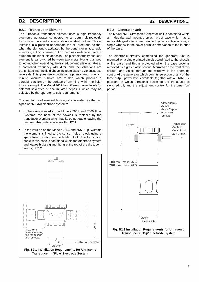
B2.1 Transducer ElementThe ultrasonic transducer element uses a high frequencyelectronic generator connected to a robust piezoelectrictransducer mounted inside a stainless steel holder. This isinstalled in a position underneath the pH electrode so thatwhen the element is activated by the generator unit, a rapidscrubbing action is carried out on the glass surface to free it ofstubborn and insoluble deposits. The piezoelectric transducerelement is sandwiched between two metal blocks clampedtogether. When operating, the transducer end plate vibrates ata controlled frequency (40 kHz), and the vibrations aretransmitted into the fluid above the plate causing violent stressreversals. This gives rise to cavitation, a phenomenon in whichminute vacuum bubbles are formed which produce ascrubbing action on the surface of anything within the fluid,thus cleaning it. The Model 7612 has different power levels fordifferent severities of accumulated deposits which may beselected by the operator to suit requirements.
The two forms of element housing are intended for the twotypes of 7650/60 electrode systems:
• In the version used in the Models 7651 and 7660 FlowSystems, the base of the flowcell is replaced by thetransducer element which has its output cable leaving theunit from the underside – see Fig. B2.1.
• In the version on the Models 7654 and 7655 Dip Systemsthe element is fitted to the sensor holder block using aspare fixing position on the holder block. The transducercable in this case is contained within the electrode systemand leaves it via a gland fitting at the top of the dip tube –see Fig. B2.2
B2.2 Generator UnitThe Model 7612 Ultrasonic Generator unit is contained withinan industrial wall mounted splash proof case which has aremovable gasketted cover retained by two captive screws; asingle window in the cover permits observation of the interiorof the case.
The electronic circuitry comprising the generator unit ismounted on a single printed circuit board fixed to the chassisof the case, and this is protected when the case cover isremoved by a grey plastic shroud. Mounted on the front of thisshroud, and visible through the window, is the operatingcontrol of the generator which permits selection of any of thethree output power levels available, together with a STANDBYposition, in which ultrasonic power to the transducer isswitched off, and the adjustment control for the timer 'on'period.
B2 DESCRIPTION B2 DESCRIPTION…
Ø61mmCable to Generator
90m
m
Allow 75mmbelow clampingring for accessand removal.
Allow approx.75 mm.above Cap foraccess andremoval
TransducerCable toControl Unit20 m. max.
75mm.Nominal Dia.
1181 mm. model 76042181 mm. model 7605
95 mm

8
…B2 DESCRIPTION
B3.1 Mounting the Generator UnitThe location selected for installing the Model 7612 will bedetermined by the position of the pH electrode system; thegenerator unit should ideally be as close to its associatedelectrode system as possible. The maximum permitted cablelength between transducer and generator is 20m (65ft).
The generator can be fixed to any convenient vertical surfacewith sufficient access to the front and with enough overheadclearance to enable the cover to be removed from its tophinges.
The overall dimensions of the case are shown in Fig. B3.1 thecase should be fixed with the two cable glands downwards ona clean dry surface in a reasonably sheltered location. Thethree fixing holes are suitable for either M6 or 1/4 in. bolts.
B3.2 Fitting the TransducerThe instructions which follow are for fitting a transducerelement to Models 7651/7660 Flow Systems or Models 7654/7655/7656 Dip Systems which is already installed and inoperation, i.e., the ultrasonic equipment is being supplied asan ‘add on’ feature to an existing installation. However, wherethe installation is new and it is required to fit the ultrasoniccleaning facility at the outset, a completely assembled systemcan be installed. The dimensions of these complete systemsare shown in Fig. B2.1 and B2.2.
B3 INSTALLATION
Fig. B3.1 Installation Requirements for Model 7612 Ultrasonic Generator
The generator unit is fitted with an electronic sequence timermounted on a single printed circuit board with a singleadjustable control (TRANSDUCER 'ON' TIME - MIN/MAX).This timer circuit, which is independent of the generator,serves to switch the generator circuit on and off in a variablemark-space mode with a total cycle time of 16 minutesapproximately. When the operating control is set at MIN(imum), the ultrasonic frequency in on for only a few seconds,whilst when it is set for MAX (imum), the ultrasonic frequencyis on for almost all the total cycle time, and switched off for onlya few seconds.
Electrical connections to the generator unit are made totwo separate screw terminal blocks mounted directly onthe chassis of the case. They are normally covered by aprotective cover which contains details of the wiringconnections – see Fig. B3.5 and Section B3.3. Cableconnections to the unit enter the case through the twosealed cable glands located at the bottom of the unit. Themaximum cable length is fitted as standard to thetransducer.
B2.3 Glass ElectrodesThe correct pH glass electrode for use when operating theModel 7612 Ultrasonic Generator is a specially developedcone head type (Part No. 1721 000 or Part No. 1723 000).These electrodes are filled with a special gel which minimisesthe effect of cavitation: they are installed in the 7650 /60 Serieselectrode systems in the same way as the conventional glasselectrodes listed in the 7650 /60 Series instruction manual.
196 mm. Fixing Centres
Earthing Screw
2 Cable Glandsfor Power Supplyand Cable toTransducer
227 mm.
202 mm.
15 mm.
3 Fixing Holesø6.4mm
Clearance for Removalof Cover 15mm.
305 mm.Fixing Centres 337 mm.
130 mm.
9
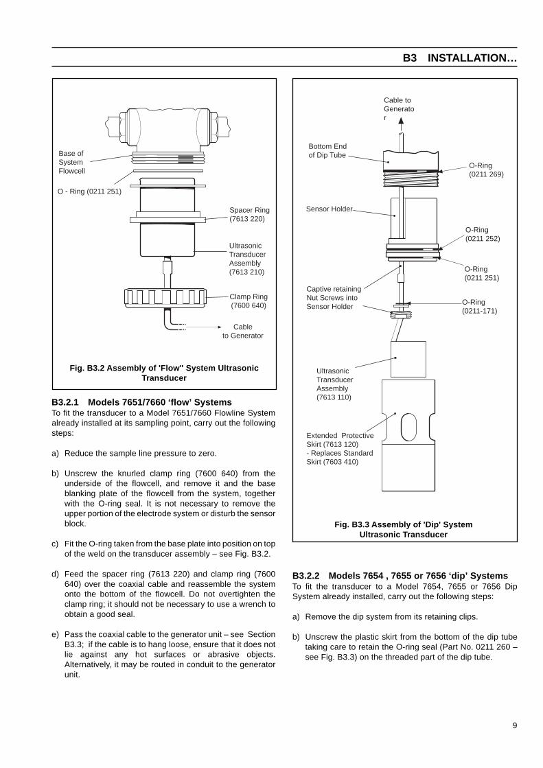
Fig. B3.2 Assembly of 'Flow" System UltrasonicTransducer
Fig. B3.3 Assembly of 'Dip' SystemUltrasonic Transducer
B3 INSTALLATION…
B3.2.2 Models 7654 , 7655 or 7656 ‘dip’ SystemsTo fit the transducer to a Model 7654, 7655 or 7656 DipSystem already installed, carry out the following steps:
a) Remove the dip system from its retaining clips.
b) Unscrew the plastic skirt from the bottom of the dip tubetaking care to retain the O-ring seal (Part No. 0211 260 –see Fig. B3.3) on the threaded part of the dip tube.
B3.2.1 Models 7651/7660 ‘flow’ SystemsTo fit the transducer to a Model 7651/7660 Flowline Systemalready installed at its sampling point, carry out the followingsteps:
a) Reduce the sample line pressure to zero.
b) Unscrew the knurled clamp ring (7600 640) from theunderside of the flowcell, and remove it and the baseblanking plate of the flowcell from the system, togetherwith the O-ring seal. It is not necessary to remove theupper portion of the electrode system or disturb the sensorblock.
c) Fit the O-ring taken from the base plate into position on topof the weld on the transducer assembly – see Fig. B3.2.
d) Feed the spacer ring (7613 220) and clamp ring (7600640) over the coaxial cable and reassemble the systemonto the bottom of the flowcell. Do not overtighten theclamp ring; it should not be necessary to use a wrench toobtain a good seal.
e) Pass the coaxial cable to the generator unit – see SectionB3.3; if the cable is to hang loose, ensure that it does notlie against any hot surfaces or abrasive objects.Alternatively, it may be routed in conduit to the generatorunit.
Base ofSystemFlowcell
O - Ring (0211 251)
Spacer Ring(7613 220)
UltrasonicTransducerAssembly(7613 210)
Cableto Generator
Clamp Ring(7600 640)
O-Ring(0211 269)
Bottom Endof Dip Tube
Sensor Holder
UltrasonicTransducerAssembly(7613 110)
Extended ProtectiveSkirt (7613 120)- Replaces StandardSkirt (7603 410)
Captive retainingNut Screws intoSensor Holder
O-Ring(0211-171)
Cable toGenerator
O-Ring(0211 252)
O-Ring(0211 251)
10
c) Rinse the sensors and sensor block with clean water anddetach it from the end of the dip tube by pulling it firmly.Unscrew and remove the glass pH electrode, temperaturecompensation sensor and sealed reference electrode fromthe sensor block. Always avoid handling the glass pHelectrode as far as possible.
d) Discard the sensor holder and take the special sensorholder (7605 056) supplied with the cleaning system.
e) Take the small O-ring seal (0211 171) and feed it over thetransducer coaxial cable until it is against the weldedflange as shown in Fig. B3.3.
f) Pass the transducer coaxial cable through the sensorblock and using a wrench (3/4 in. or 19mm A/F) screw thestainless steel captive retaining nut into the recessed hole.It is advisable to use PTFE thread seal tape to ensure agood seal. When the retaining nut is screwed in firmly, thetop surface of the transducer casing should locate beneaththe glass bulb of the pH electrode at approximately. 10mm (3/8 in.) below it.
g) Fit the glass electrode and sealed reference electrode tothe sensor block, taking care to retain their O-ring seals inposition.
h) Fit the sensor block (with transducer now attached) to thebottom of the dip tube: the block locates with a smallkeyway and should be firmly inserted home.
i) Screw onto the bottom of the dip tube the extendedprotective skirt (7613 120) in place of the skirt removed instep b). The replacement skirt is longer and serves to givesome degree of mechanical protection against debris, etc.,when the dip system is installed at its sampling point.
j) Remove the orange top cap from the dip system and feedthe coaxial cable from the transducer up the length of thedip tube and out of the side cable gland diametricallyopposite the gland carrying the multiway cable to the pHmeter. To obtain a satisfactory seal on the transducercable, the existing cable bush in the gland should bereplaced by the bush (7613 150).
k) Replace the orange top cap and tighten the cable gland.
l) Replace the dip system in its sampling point and pass thetransducer cable to the generator unit (see next section forelectrical connections): if the cable is to hang loose, ensurethat it does not lay against any hot surfaces or abrasiveobjects. Alternatively, it may be routed in conduit to thegenerator unit.
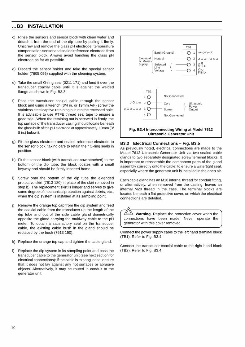
Fig. B3.4 Interconnecting Wiring at Model 7612Ultrasonic Generator Unit
TB1
1
2
3
4
E A R T HEarth (Ground)
Neutral
SelectedLineVoltage
Electricalac MainsSupply
N E U T R A L
95/
120
V
220/
250
V
TB2
1
2
3
4
C O R E
S C R E E N
Not Connected
Core
Screen
Not Connected
UltrasonicPowerOutput
…B3 INSTALLATION
B3.3 Electrical Connections – Fig. B3.5As previously noted, electrical connections are made to theModel 7612 Ultrasonic Generator Unit via two sealed cableglands to two separately designated screw terminal blocks. Itis important to reassemble the component parts of the glandassembly correctly onto the cable, to ensure a watertight seal,especially where the generator unit is installed in the open air.
Each cable gland has an M16 internal thread for conduit fitting,or alternatively, when removed from the casting, leaves aninternal M20 thread in the case. The terminal blocks arelocated beneath a flat protective cover, on which the electricalconnections are detailed.
Warning. Replace the protective cover when theconnections have been made. Never operate thegenerator with this cover removed.
Connect the power supply cable to the left hand terminal block(TB1). Refer to Fig. B3.4.
Connect the transducer coaxial cable to the right hand block(TB2). Refer to Fig. B3.4.

11
Fig. B3.5 Controls and ElectricalInterconnections on Model 7612 Ultrasonic
Generator Unit
When the electrical connections to the generator unit havebeen satisfactorily completed, and the modified electrodesystem reinstalled at its sampling point, the ultrasonic cleaningsystem can be set in operation by simply turning the frontpanel control switch from STANDBY to one of the threeavailable power levels - LOW, MEDIUM or HIGH. Refer to Fig.B3.5.
The choice of power setting is determined largely by theparticular application in which the pH measurement is beingmade: if it has already been established that ultrasoniccleaning is desirable, some impression will already have beengained of the rate of accumulation of debris, fouling of theglass membrane etc. Similarly, the rate of cleaning(determined by the MIN/MAX control setting) will depend uponthe application. Adjustment over a period will determine theoptimum setting to ensure satisfactory cleaning withoutunnecessary power consumption.
Two points concerning the operation of the generator unitshould be particularly noted:
• Never operate the generator with the transducerdisconnected i.e. open circuit output.
• Do not operate the generator with the transducer dry i.e.not immersed in sample: the power dissipation in thetransducer will cause overheating after a short period andconsequent possible damage to the piezoelectric ceramicif the temperature rises too high. Thus it should always bechecked that sample is available in the case of the flowsystem (Model 7651) before operating the generator unit.
Replace the cover on the generator unit after setting the powerselector switch to the desired position, and the MIN/MAXcontrol to the optimum setting.
B4 SETTING-UP …B4 SETTING-UP
DANGER LIVE TERMINALSISOLATE SUPPLY BEFORE REMOVING
THIS COVER
ULTRASONICPOWER
STANDBY
LOW
MED
HIGHMIN MAX
TRANSDUCER'ON' TIME
7612
EARTH
NEUTRAL
95/120V
220/250V
CORE
SCREEN
A.C.PowerSupply Connections
Transducer CoaxialCable Connections
TB1 TB2

12
Apart from an occasional check that the ultrasonic cleaningaction is operating (the action should be audible whenstanding close to the electrode system), it is not anticipatedthat the generator unit or the transducer assembly will requireany regular maintenance. However, the sensors in theelectrode system will require changing when they reach theend of their useful life, and a quick check of the cleanliness ofthe transducer will indicate the efficiency of the cleaningsystem. At the same time, the coaxial transducer cable shouldbe checked for signs of possible wear or fraying.
B5.1 Changing the SensorsInstructions are given in the 7600 Series instruction manual forreplacing any of the sensors in the electrode system, and theinstruction manual (normally supplied with the electrodesystem) should be consulted when this becomes necessary.When the electrode system is fitted with an ultrasonictransducer, it should not be necessary to remove thetransducer when changing sensors. When replacing a glasselectrode ensure that it is firmly held in the sensor block by itsO-ring seal and clamp nut, so that it is absolutely rigid. Thebulb of the electrode should be positioned approximately10mm (3/8 in.) above the top surface of the transducer whencorrectly located.
B5 ROUTINE MAINTENANCE
The following suggested spare items are available from ABBKent-Taylor Limited, Oldends Lane, Stonehouse,Gloucestershire, England, GL10 3TA by quoting the Part No.below.
Spares items for the appropriate electrode system are listed inthe 7650 /60 Series instruction manual.
Item Kent-Taylor Part No.
Printed circuit board assembly,complete (ultrasonic generator) 0232 042Printed circuit board assembly,complete (electronic timer) 7612 200Supply transformer 0315 210Transducer assembly(for 76517660 flow systems) 7613 210Transducer assembly(for 7654 or 7655 dip system) 7613 110pH glass electrode (industrial) 1021 000pH glass electrode (low temp.) 1023 000
The ‘add-on’ kit for converting an existing 76517660 flowsystem contains the following items, as shown in Fig. B3.2:
Item Kent-Taylor Part No.Kit 7613 200
Contents:O-ring (0211 251)(to seal welded flangeto bottom of flowcell)Spacer ring (7613 220)Transducer (7613 210)assembly (flow type)
The ‘add-on’ kit for converting an existing 7654 or 7655 dipsystem contains the following items, as shown in Fig. B3.3.
ItemKent-Taylor Part No.Kit 7613 100
Contents:O-ring (0211 171)(to seal weldedflange of transducerstem to sensor block)Special extended skirt (7613 120)(replaces the standardskirt fitted)Gland bush (7613 150)(has enlarged hole fortransducer coaxial cable)Transducer assembly (7613 110)(dip type)
Sensor holder (7650 056)
B6 SPARE PARTS

13
Generator output: Three settings of 9, 18 or 35 watts approximately.
Output frequency:40kHz nominal
Sequence timer:Single variable control alters on/off ratio from aminimum of a few seconds to a maximum ofapproximately. 15 minutes., within a total cycle time of16 minutes approximately.
SamplePressure:172kNm–2 (25lbfin–2) max. (flow system)
Power supply:95 to 120V or 220 to 250V, 50 to 60Hz
Power consumption:Max. approximately 80VA
B7 SPECIFICATION …B7 SPECIFICATION
Separation:Max. cable length between transducer and generator20m (65ft). Standard cable length 20m (65ft)approximately.
Dimensions of Generator:227 x 337 x 130mm – see Fig. B3.1 (8.94 x 13.25 x
5.13in.)
Fixing:Three fixing holes ø6.4mm (0.2in.) on centres 196mm(7.72in.) and 305mm (12.0in.) – see Fig. B3.1.
Dimensions of transducer:When fitted to a Model 7651 or 7660 system, addsapproximately 38mm (1.5in.) to the overall length of theelectrode system – see Fig. B2.1. When fitted to aModel 7654, 7655 or 7656 system, addsapproximately. 64mm (2.52in.) to the overall length ofthe electrode system –see Fig. B2.2
14
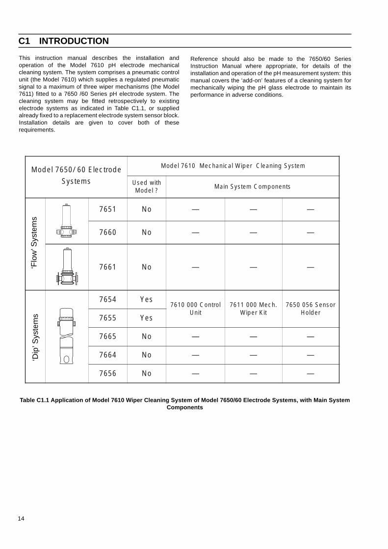
Table C1.1 Application of Model 7610 Wiper Cleaning System of Model 7650/60 Electrode Systems, with Main SystemComponents
This instruction manual describes the installation andoperation of the Model 7610 pH electrode mechanicalcleaning system. The system comprises a pneumatic controlunit (the Model 7610) which supplies a regulated pneumaticsignal to a maximum of three wiper mechanisms (the Model7611) fitted to a 7650 /60 Series pH electrode system. Thecleaning system may be fitted retrospectively to existingelectrode systems as indicated in Table C1.1, or suppliedalready fixed to a replacement electrode system sensor block.Installation details are given to cover both of theserequirements.
C1 INTRODUCTION
Reference should also be made to the 7650/60 SeriesInstruction Manual where appropriate, for details of theinstallation and operation of the pH measurement system: thismanual covers the ‘add-on’ features of a cleaning system formechanically wiping the pH glass electrode to maintain itsperformance in adverse conditions.
‘Flo
w’ S
yste
ms
‘Dip
’ Sys
tem
s
edortcelE06/0567ledoM metsySgninaelCrepiWlacinahceM0167ledoM
smetsyS htiwdesU?ledoM
stnenopmoCmetsySniaM
1567 oN — — —
0667 oN — — —
1667 oN — — —
4567 seYlortnoC0000167
tinU.hceM0001167
tiKrepiWrosneS6500567
redloH5567 seY
5667 oN — — —
4667 oN — — —
6567 oN — — —

15
C2.2 Model 7610 Control UnitThe Control Unit is mounted inside a cast-alloy weatherproofcase suitable for direct wall-mounting at a convenient locationnear the associated pH electrode system. The case has aremovable gasketted cover fastened with a central quick-release knob and an inset plastic lens covering the RUN lampon the front panel.
Removal of the cover permits access to the front panel andcontrols of the unit: the front panel is supported by pillars ateach corner of the chassis so that a small printed circuit boardassembly is mounted beneath it, and space remains under theboard for the pneumatic components fixed to the chassis.
The front panel controls (see Fig. C3.4) and their functions areas follows:
RUN/STANDBY: miniature toggle switch
In the STANDBY (down) position, power isdisconnected from the electronic circuitry and solenoidvalve : in the RUN (up) position power is connected tothe instrument and the RUN lamp (green lens on thecover) illuminates.
RESET: toggle switch, biased to the ‘up’ position
Depressing this switch resets the electronic timing tothe beginning of its cycle.
Interval Selector: slide switch (8 positions) C, 1, 4, 16,32 minutes) 1, 2, 8 hours )
Sets the interval duration between the cleaning actionsin the C position wiping is continuous, in the remainingpositions four wiping cycles occur at the beginning ofthe selected period.
In addition to the electrical controls listed above there are twopneumatic adjustment controls located at the bottom of thecase – see also Fig. C3.4). These are the air pressureregulator control knob (fitted with a red locking ring), used toset the operating pressure for the actuator at 4 bars (58lbfin–2)approximately, and the restrictor adjuster fitted to the exhaustoutlet. Adjusting the restrictor gives some control over thesmoothness of the wiping action : depending upon the type anddegree of accumulation of deposits on the pH electrode, thebrush can be wiped smoothly or abruptly across the tip of theglass bulb. These adjustments are described more fully in the‘Setting up’ section.
Pneumatic connections to the Model 7610 are made usingplastic bulkhead connectors at the bottom of the case suitablefor 6mm nylon tubing.
Power supply cable enters the Model 7610 by a single sealedcable gland and connects directly to a small terminal blocklocated under a protective cover on the left-hand side of theunit. An additional earthing connector (screw terminal) isprovided at the side of the instrument panel, if required.
C2 DESCRIPTION C2 DESCRIPTION…
C2.1 Principle of Operation (Fig. 3.2)Clean dry filtered air is supplied to the Model 7610 Control Unitfrom an air-line or other source in the range 550 to 690kNm–2
(80 to 100lbfin–2), regulated and passed via a multi-portsolenoid valve to a double-acting pneumatic actuator mountedalongside the pH sensors on the electrode system sensorblock (see Fig. C3.5). This pneumatic actuator is a small brasscylinder with two pipe couplings to which are connected to thetwo pneumatic lines from the Control Unit. When the solenoidvalve is energised, the transmitted air pressure operates theactuator piston to provide a stroke of about 25mm (1in.) andthis is converted to arc motion (about 45°) by a cleaning rodfixed so that a transverse pin on the end of the actuator pistonlocates in a spiral groove on the top of the rod. At the bottomend of the rod is fitted the wiper assembly which is a smallpolypropylene brush positioned so that the twisting motion ofthe cleaning rod wipes the brush across the tip of the glassbulb of the pH electrode, serving to keep it clean of deposits oraccumulated debris.
A printed circuit board assembly in the Control Unit contains atiming circuit to energise the solenoid valve, so that the wiperoperates continuously or at set intervals, depending on aposition selected by a front panel slide switch.
16
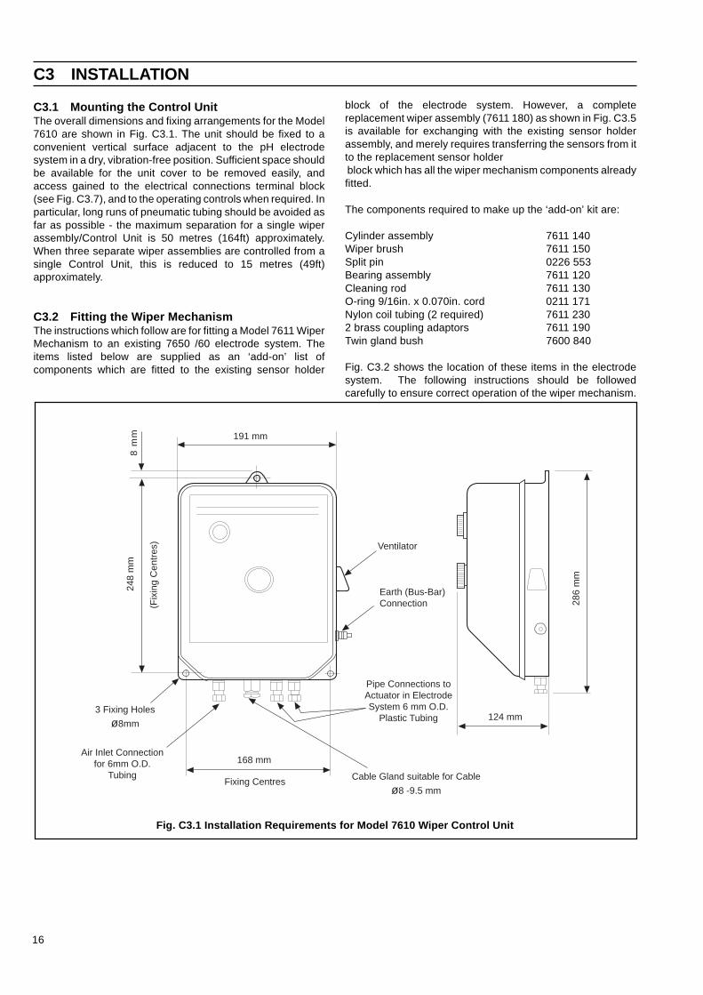
C3.1 Mounting the Control UnitThe overall dimensions and fixing arrangements for the Model7610 are shown in Fig. C3.1. The unit should be fixed to aconvenient vertical surface adjacent to the pH electrodesystem in a dry, vibration-free position. Sufficient space shouldbe available for the unit cover to be removed easily, andaccess gained to the electrical connections terminal block(see Fig. C3.7), and to the operating controls when required. Inparticular, long runs of pneumatic tubing should be avoided asfar as possible - the maximum separation for a single wiperassembly/Control Unit is 50 metres (164ft) approximately.When three separate wiper assemblies are controlled from asingle Control Unit, this is reduced to 15 metres (49ft)approximately.
C3.2 Fitting the Wiper MechanismThe instructions which follow are for fitting a Model 7611 WiperMechanism to an existing 7650 /60 electrode system. Theitems listed below are supplied as an ‘add-on’ list ofcomponents which are fitted to the existing sensor holder
block of the electrode system. However, a completereplacement wiper assembly (7611 180) as shown in Fig. C3.5is available for exchanging with the existing sensor holderassembly, and merely requires transferring the sensors from itto the replacement sensor holder block which has all the wiper mechanism components alreadyfitted.
The components required to make up the ‘add-on’ kit are:
Cylinder assembly 7611 140Wiper brush 7611 150Split pin 0226 553Bearing assembly 7611 120Cleaning rod 7611 130O-ring 9/16in. x 0.070in. cord 0211 171Nylon coil tubing (2 required) 7611 2302 brass coupling adaptors 7611 190Twin gland bush 7600 840
Fig. C3.2 shows the location of these items in the electrodesystem. The following instructions should be followedcarefully to ensure correct operation of the wiper mechanism.
C3 INSTALLATION
Fig. C3.1 Installation Requirements for Model 7610 Wiper Control Unit
3 Fixing Holes
ø8mm
Air Inlet Connectionfor 6mm O.D.
Tubing
168 mm
Fixing Centres
Ventilator
Earth (Bus-Bar)Connection
Pipe Connections toActuator in ElectrodeSystem 6 mm O.D.
Plastic Tubing
Cable Gland suitable for Cable
ø8 -9.5 mm
124 mm
286
mm
191 mm
8 m
m 2
48 m
m
(Fix
ing
Cen
tres
)

17
Warning. Always ensure in the case of in-linesystems that the sample line pressure is reduced to zerobefore removing the electrode assembly from thesampling point.
Caution. Complete this procedure within 2 hours,or take steps to avoid drying out and degradation ofelectrodes.
a) Dismantle the electrode system so as to gain access to thesensor holder assembly; steps are given in the 7650 /60Series instruction manual to do this.
b) Rinse the sensor holder assembly in clean water andremove the glass pH electrode, the temperaturecompensation sensor and the reference electrode from thesensor holder .
c) Discard the sensor holder and take the special sensorholder (7605 056) supplied with the cleaning system.
d) Take the cylinder assembly from the kit and using a pair ofpliers, push the pin fitted to the end of the actuator rod fromits central position to one side. This will now permit thecylinder (with actuator extended) to be screwed into thesensor holder from the top side. The interior thread of theactuator housing has a slotted cut-out to enable the pin topass through the sensor block completely.
e) Screw the cylinder assembly firmly into the sensor blockand use the brass locking nut on the threaded portion toposition the cylinder so that the pipe fitting on the side ofthe cylinder does not obstruct either the glass electrodeclamp nut or the reference electrode, when these are fittedback into the sensor block. Tighten the locking nut.
f) Using a pair of pliers, push the pin back to its centralposition.
g) Fit the O-ring (0211 171) from the kit into the groove on thesensor side of the block (position as shown in Fig. C3.2)and fit the cleaning rod (7611 130) so that the pin locates inthe end of the rod in its spiral grooves.
h) Pass the bearing assembly (7611 120) over the cleaningrod and screw into the sensor block to hold the completeassembly together firmly.
i) Fit the wiper brush onto the squared end of the cleaningrod by pushing it on. The brush should locate over theglass electrode position, so that when the electrode isinserted in the block, the brush just touches the tip of theglass bulb. See Fig. C3.3. Fit the split pin in the locatinghole and bend over the ends with pliers.
INSTALLATION…
Fig. C3.2 Assembly of Wiper Unit
PolypropyleneWiper Assembly(7611 150)
O-Rings(0211 139)
BearingAssembly(7611 120)
Split Pin0226 553
ReferenceElectrode
TemperatureCompensator Cleaning
Rod(7611 130)
GlassElectrode
O-Ring(0211 171)
PneumaticActuator(7611 140)
Performed CoiledNylon Tubing(7611 230)
To 7610 Control Unit (viaCoupling Adaptors 7611 190 )
O-Ring(0211 252)
O-Ring(0211 252)

18
Fig. C3.3 Positioning of Wiper Relative to MeasurementElectrode
j) Take the two nylon preformed coils (7611 230) from the kitand fit one to each of the pipe fittings on the cylinderassembly. It is important in order to obtain a good seal thatthe brass gland couplings are tightly clamped onto thetubing. Depending upon the particular type of 7650 /60system, it will be necessary to cut the nylon tubing so thatit can be accommodated within the electrode system tube.The other ends of the preformed coils should be fed out ofthe side cable gland, using the twin gland bush (7600 840)from the kit to replace the existing sealing bush.
Tighten the gland nut firmly onto the bush. The reason forusing a preformed coil inside the tube is so that it will bepossible at a later date to detach the sensor blockassembly from the system tube (for examination orreplacement of sensors) without needing to disturb thepneumatic connections to the cylinder assembly – see Fig.C3.5.
k) Refit the pH glass electrode, temperature compensationsensor and reference electrode assembly into the sensorholder in accordance with the information given in the7650/60 electrode system manual.
l) Re-assemble the electrode system by inserting the sensorblock into the bottom of the electrode holder unit (locateusing the keyway on the sensor holder block) and clampingthe holder unit to the in-line process fitting using theclamping ring.
Where the complete replacement wiper assembly (7611 180)is supplied, it is of course not necessary to carry out theassembly steps detailed above. In this case, it remains only totransfer the pH glass electrode, the reference electrode andtemperature compensator to the replacement sensor holderblock and fit it to the electrode system. Take care to handle thesensors carefully at all times, and remember to fill thetemperature compensator housing with paraffin oil (supplied inthe kit) before inserting the compensator with its snap-onconnector.
Fig.C3.4 Controls, Indicators and MechanicalInterconnections on Model 7610 Wiper Control Unit
C3.3 Pneumatic ConnectionsAs shown on Fig. C3.1 the air inlet to the Model 7610 ControlUnit is suitable for 6mm o.d. tubing; the connection is the left-hand gland fitting on the underside of the Control Unit. The airsupply should be dry clean filtered air at a maximum pressureof 690kNm–2 (100lbfin–2).
The other two gland fittings on the underside of the Model7610 are the connections to the two lengths of preformednylon tubing fixed to the actuator. The gland fittings on theModel 7610 are suitable for 6mm o.d. nylon tubing and mustbe joined to the wiper mechanism tubing, using the brassadaptors (7611 190) supplied in the kit. These adaptors can belocated conveniently just outside the electrode system (asshown in Fig. C3.5 (It is not important which way round theconnections are made, since the actuator is a double-actingcylinder).
Where more than one electrode system is to be supplied froma single Model 7610, the brass adaptors will need to bereplaced by an appropriate adaptor Tee-piece fitting (6mminlet and 6mm outlet).
…INSTALLATION
MeasurementElectrodePositionWiper
Approximately 30°
INTERVALSELECTOR
RUN
STANDBY RESET
7610 ELECTRODE CLEANING CONTROL UNIT
Air in Air toactuator
Air toactuator
Restrictor

19
Fig. C3.5 Wiper Unit and Interconnecting Air Lines
INSTALLATION…
Sensor Holder
Wiper Brush
PneumaticActuator
Split Pin

20
Fig. C3.7 Location of Items and electricalInterconnections on Model 7610 Wiper Control Unit
C3.4 Electrical ConnectionsThe electrical power supply connections to the Model 7610enter the instrument via a single waterproof gland which canaccommodate a single three-core cable in the range 8 to 9mm( 0.31 to 0.38in) diameter. Care should be taken to re-assemble the component parts to ensure a watertight fit.
Cable connections are made to a single multi-way terminalblock (TB1) which is located beneath a labelled cover plate onthe left-hand side of the main chassis (see Fig. C3.7). Thecable passes through a grommet fixing on the connectionbracket and is then connected to the labelled terminals asindicated in Fig. C3.6. Select the required LINE terminaldepending on the electrical power supply.
✶ Note. There is an additional earth point on the case(see Fig. C3.1) where an earthing (bus-bar) screwconnection is provided.
Always replace the terminal coverplate after making the wiringconnections.
C4 SETTING-UP
When the installation steps detailed above have beencompleted, the Model 7610 is ready for operation. Carry outthe following steps:
a) With the air-line connected to the Model 7610 (maximumpressure 690 kN/m2 or 100 lbf/in2), remove the lid of theunit and first check that the pressure regulator control knob(the black plastic knob with red locking ring) is turned fullyanti-clockwise (as viewed from the underside of the unit) toclose off the air supply. See Fig. C3.7.
Fig. C3.6 Interconnecting Wiring at Model 7610 WiperControl Unit
…INSTALLATION
b) Pull the red locking ring downwards to disengage it, andslowly turn the black control knob clockwise until thepressure gauge indicates an operating pressure of 4 bars(58lbfin–2) approx. For long pipe runs over 30 metres (98ft)it is recommended to open the pressure regulator fully sothat the gauge indicates the inlet pressure supply of 6.9bars (100 lbfin–2).
c) Push the red locking ring upwards to hold the control knobin position.
d) Set the INTERVAL SELECTOR slide switch to theappropriate position estimated for a satisfactory cleaningaction. This will depend largely on the particular applicationand previous experience of the degree of electrode foulingwill be a useful guide to selecting the optimum frequency ofcleaning.
e) Connect the power supply to the instrument, and set theRUN/STANDBY switch to RUN. Note that the RUN lamp(green lens) illuminates.
f) Depress the RESET switch : the unit should now performfour cycles (four wipes in each direction) and then wait fora period set by the INTERVAL SELECTOR switch beforerepeating the wiping action. If the INTERVAL SELECTORswitch is set to C (for continuous action), it is not necessaryto operate the RESET switch a the cleaning action willstart immediately.
C4 SETTING-UP…
TB1
1
2
3
4
5
6
E
N
95/105V
110/120V
220/230V
240/250V
Earth (Ground)
Neutral
SelectedLineVoltage
Electricalac MainsSupply
Solenoid Valve
200 mA 20 x 5 mm FuseholderPrinted Circuit Board Assembly'Run' Lamp300 mA 20 x 5 mm Fuseholder
Run/Standby Switch
Coverplate foTerminals
Terminal Block Label(Power Supply Connections)
Pressure Gauge
Cable Grommet
Red Locking Ring
Regulator Control Knob
E
N
95/105
110/120V
220/230V
220/250V

21
…C4 SETTING-UP
C5.2 Changing the SensorInstructions are given in the 7650/60 Series instruction manualfor replacing any of the sensors in the electrode system, andthe instruction manual should be consulted when thisbecomes necessary. When the electrode system is fitted witha wiper mechanism, it should not be necessary to remove anyof the wiper components from the sensor block to exchangesensors. When fitting a new glass electrode ensure that it istightly held in the block by its clamp nut so that the electrode isrigid. The bulb of the electrode should just touch the bottom ofthe ‘trough’ section of the wiper bristles when correctly locatedin position.
C5.3 FusesOn the top left-hand side of the printed circuit board (as viewedfrom the front) are located two fuseholders which containminiature 20x5mm DIN cartridge fuses.
The upper fuse is a 200mA fuse and protects the 16.5V a.c.supply to the timing circuit. If it fails, the timing and wipingaction will cease completely. The part number for areplacement fuse is 0231 546.
The lower fuse is a 300mA fuse and protects the solenoidvalve supply (24V a.c.). If it fails, the solenoid will not operateand the wiping action will cease completely. The part numberfor a replacement fuse is 0231 547.
g) If at any time it is required to check that the cleaning actionis still operating, depressing the RESET switch will cause acleaning cycle to restart immediately.
h) If necessary, adjustment of the flow restrictor can be madeto provide a smoother wiping action or a more abrupt ‘wipe’if this is required. Loosening the brass restrictor ensures astronger ‘kick’ of the wiper arm across the electrode, whilstfrom the front) are located two fuseholders which containminiature 20 x 5mm DIN glass cartridge fuses.
Tightening the restrictor has the effect of slowing down thewiper stroke and produces a smoother ‘wipe’. Again,experience is the best guide for finding an optimumadjustment position for a particular application.
i) When the system is operating satisfactorily, replace thecover on the unit.
C5 MAINTENANCE
Apart from an occasional check that the cleaning action is stilloperating periodically, it is not anticipated that once set inoperation the Model 7610 will require any maintenance on aregular basis apart from changing the wiper brush. The brushwill after extended use eventually no longer wipe satisfactorilyand clean the electrode bulb, and it will be necessary to fit anew brush assembly.
Supplied in the spares kit is a sachet of lubricating grease,which should be used to lubricate the O-rings in the system.
C5.1 Changing the Wiper AssemblyWhen it becomes apparent from the pH readings that thebrush is no longer wiping satisfactorily, carry out the followingsteps:
a) Set the RUN/STANDBY.
b) Remove the electrode holder unit from its samplingposition by unscrewing the large clamping ring holding thetwo halves of the electrode system together.
Warning. In the case of in-line systems, firstensure that the sample line pressure is reduced to zerobefore separating the holder unit from the system.
c) Remove the split pin and pull off the wiper assembly fromthe end of the cleaning rod and replace with a new wiper(7611 150). Discard the old wiper assembly. It is importantthat the new wiper is fitted in exactly the same position onthe squared end of the cleaning rod as the old wiper, toensure that the arc motion across the electrode bulb is inthe same position to maintain the cleaned area on the bulb.
…C5 MAINTENANCE
22
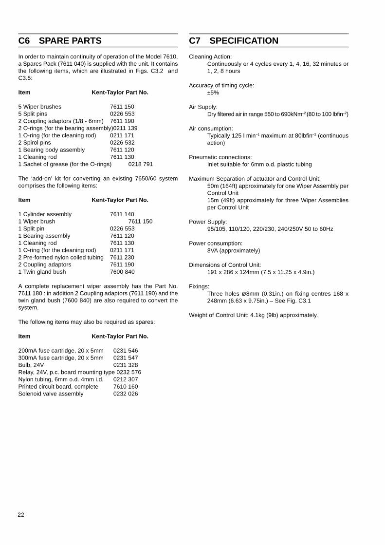
C6 SPARE PARTS
In order to maintain continuity of operation of the Model 7610,a Spares Pack (7611 040) is supplied with the unit. It containsthe following items, which are illustrated in Figs. C3.2 andC3.5:
Item Kent-Taylor Part No.
5 Wiper brushes 7611 1505 Split pins 0226 5532 Coupling adaptors (1/8 - 6mm) 7611 1902 O-rings (for the bearing assembly)0211 1391 O-ring (for the cleaning rod) 0211 1712 Spirol pins 0226 5321 Bearing body assembly 7611 1201 Cleaning rod 7611 1301 Sachet of grease (for the O-rings) 0218 791
The ‘add-on’ kit for converting an existing 7650/60 systemcomprises the following items:
Item Kent-Taylor Part No.
1 Cylinder assembly 7611 1401 Wiper brush 7611 1501 Split pin 0226 5531 Bearing assembly 7611 1201 Cleaning rod 7611 1301 O-ring (for the cleaning rod) 0211 1712 Pre-formed nylon coiled tubing 7611 2302 Coupling adaptors 7611 1901 Twin gland bush 7600 840
A complete replacement wiper assembly has the Part No.7611 180 : in addition 2 Coupling adaptors (7611 190) and thetwin gland bush (7600 840) are also required to convert thesystem.
The following items may also be required as spares:
Item Kent-Taylor Part No.
200mA fuse cartridge, 20 x 5mm 0231 546300mA fuse cartridge, 20 x 5mm 0231 547Bulb, 24V 0231 328Relay, 24V, p.c. board mounting type 0232 576Nylon tubing, 6mm o.d. 4mm i.d. 0212 307Printed circuit board, complete 7610 160Solenoid valve assembly 0232 026
Cleaning Action:Continuously or 4 cycles every 1, 4, 16, 32 minutes or1, 2, 8 hours
Accuracy of timing cycle:±5%
Air Supply:Dry filtered air in range 550 to 690kNm–2 (80 to 100 lbfin–2)
Air consumption:Typically 125 l min–1 maximum at 80lbfin–2 (continuousaction)
Pneumatic connections:Inlet suitable for 6mm o.d. plastic tubing
Maximum Separation of actuator and Control Unit:50m (164ft) approximately for one Wiper Assembly perControl Unit15m (49ft) approximately for three Wiper Assembliesper Control Unit
Power Supply:95/105, 110/120, 220/230, 240/250V 50 to 60Hz
Power consumption:8VA (approximately)
Dimensions of Control Unit:191 x 286 x 124mm (7.5 x 11.25 x 4.9in.)
Fixings:Three holes ø8mm (0.31in.) on fixing centres 168 x248mm (6.63 x 9.75in.) – See Fig. C3.1
Weight of Control Unit: 4.1kg (9lb) approximately.
C7 SPECIFICATION

PRODUCTS & CUSTOMER SUPPORT
A Comprehensive Instrumentation Range
Analytical Instrumentation• Transmitters
On-line pH, conductivity, and dissolved oxygentransmitters and associated sensing systems.
• SensorspH, redox, selective ion, conductivity and dissolvedoxygen.
• Laboratory InstrumentationpH and dissolved oxygen meters and associatedsensors.
• Water AnalyzersFor water quality monitoring in environmental, powergeneration and general industrial applications including:pH, conductivity, ammonia, nitrate, phosphate, silica,sodium, chloride, fluoride, dissolved oxygen andhydrazine.
• Gas AnalyzersZirconia, katharometers, hydrogen purity and purge-gasmonitors, thermal conductivity.
Controllers & Recorders• Controllers
Digital display, electronic, pneumatic. Discrete single-loop and multi-loop controllers which can be linked to acommon display station, process computer or personalcomputer.
• RecordersCircular and strip-chart types (single and multi-point) fortemperature, pressure, flow and many other processmeasurements.
Electronic Transmitters• Smart & Analog Transmitters
For draft, differential, gauge and absolute pressuremeasurement. Also, liquid level and temperature.
• I to P Converters and Field Indicators
Flow Metering• Magnetic Flowmeters
Electromagnetic, insertion type probes and watermeters.
• Turbine Flowmeters
• Wedge Flow Elements
• Mass Flow MetersTransmitters, sensors, controllers and batch/displayunits.
Level Control• Submersible, Capacitance & Conductivity.
Pneumatic Instrumentation• Transmitters
• Indicating Controllers
• Recording Controllers
Customer Support
ABB Instrumentation provides a comprehensive after salesservice via a Worldwide Service Organization. Contact one ofthe following offices for details on your nearest Service andRepair Centre.
United KingdomABB Instrumentation LimitedTel: +44 (0)1480 475321Fax: +44 (0)1480 470787
United States of AmericaABB Instrumentation Inc.Tel: +1 716 292 6050Fax: +1 716 273 6207
ItalyABB Kent-Taylor SpATel: +39 (0) 344 58111Fax: +39 (0) 344 58278
Client Warranty
Prior to installation, the equipment referred to in this manualmust be stored in a clean, dry environment, in accordance withthe Company's published specification. Periodic checks must bemade on the equipment's condition.
In the event of a failure under warranty, the followingdocumentation must be provided as substantiation:
1. A listing evidencing process operation and alarm logs at timeof failure.
2. Copies of operating and maintenance records relating to thealleged faulty unit.

The Company’s policy is one of continuous productimprovement and the right is reserved to modify the informationcontained herein without notice.
© ABB 1999 Printed in UK (5.99)
ABB Instrumentation LtdSt. NeotsCambs.England, PE19 3EUTel: +44 (0) 1480 475321Fax: +44 (0) 1480 217948
ABB Automation IncInstrumentation DivisionPO Box 20550, RochesterNew York 14602-0550USATel: +1 716 292 6050Fax: +1 716 273 6207
ABB Kent-Taylor SpA22016 LennoComoItalyTel: +39 (0) 344 58111Fax: +39 (0) 344 58278
IM/7
600–
CLN
Issu
e 1