ranger 7600 downloadable control communicator installation...
TRANSCRIPT
RANGER 7600
DOWNLOADABLE CONTROL COMMUNICATOR
INSTALLATION MANUAL
CADDX-CADDI CONTROLS INC.
GLADEWATER, TEXAS
800-727-2339
TABLE OF CONTENTS
1. TABLE OF CONTENTS ....................................................................................................................... P.1 2. GENERAL DESCRIPTION................................................................................................................... P.2.........3. STANDARD AND OPTIONAL PARTS LIST ......................................................................................... P.2.........4. FEATURE DEFINITIONS ..................................................................................................................... P.3
5. TERMINAL DRAWING AND SPECIAL NOTES .................................................................................... P.4
6. TERMINAL DESCRIPTION.................................................................................................................. P.5
7. HOW TO PROGRAM THE RANGER 7600 .......................................................................................... P.6
8. KEYPAD PROGRAMMING EXAMPLES .............................................................................................. P.7
9. OPTIONAL #8950 PROGRAMMER EXAMPLE .................................................................................... P.7
10. REQUIRED PROGRAMMING INSTRUCTIONS.............................................................................. P.8-9
11. COMMUNICATOR FORMAT SELECTION GUIDE............................................................................. P.9
12. OPTIONAL PROGRAMMING INSTRUCTIONS........................................................................... P.10-25
13. DOWNLOAD PROGRAMMING INSTRUCTIONS............................................................................. P.26
14. PROGRAMMING WORKSHEETS............................................................................................... P.27-30
15. APPENDIX 1.................................................................................................................................... P.31
16. APPENDIX 2.................................................................................................................................... P.32
17. LOCAL TELEPHONE COMPANY INTERFACE INFORMATION ...................................................... P.33
18. SPECIFICATIONS & WARRANTY .......................................................... .............................. P.34

2
RANGER 7600INSTALLATION MANUAL
General Description
The Ranger 7600 is a versatile up/downloadable security control with four EOL supervised zones and two non-supervised normally closed zones. Its microcomputer design provides some of the most versatile, yet easy to usefeatures available for most security applications today. Each of the four supervised zones can be programmed tobe one of nine different types including 24 Hour, Interior Follower, and Day zone. The two non-supervised zonescan be programmed for any of the available zone types excluding "FIRE". Each zone is individually annunciatedand can be bypassed from the keypad. See page 11 for a description of all zone types.
Read the OPERATORS MANUAL before you begin the installation for the best overall description of how theRanger 7600 functions. After installation of the security system, complete the information on page 1 of theoperators manual and explain the system operation to all security system owners/operators.
Standard Parts List
The Ranger 7600 is shipped with the parts listed below.
QUANTITY PART DESCRIPTION PART NO.
1 MASTER CONTROL PANEL W / O Keypad 7605
8 3.3K, 1/2 WATT E.O.L. RESISTORS EOL-33
1 INSTALLATION MANUAL IM-7600
1 OPERATORS MANUAL OM-7600
Optional Parts List.
The following parts are available for use with the Ranger 7600.
OPTIONAL PARTS DESCRIPTION PART NO.
LED REMOTE KEYPAD 8002
LCD ALPHA NUMERIC DISPLAY KEYPAD 9050
AC POWER SUPPLY 16.5V 25 VA T-16.5-25
PROGRAMMER WITH DIGITAL NUMERIC DISPLAY 8950
SMART PROGRAMMER WITH LCD DISPLAY 9075
DOWNLOADING SOFTWARE PACKAGE DL900
3
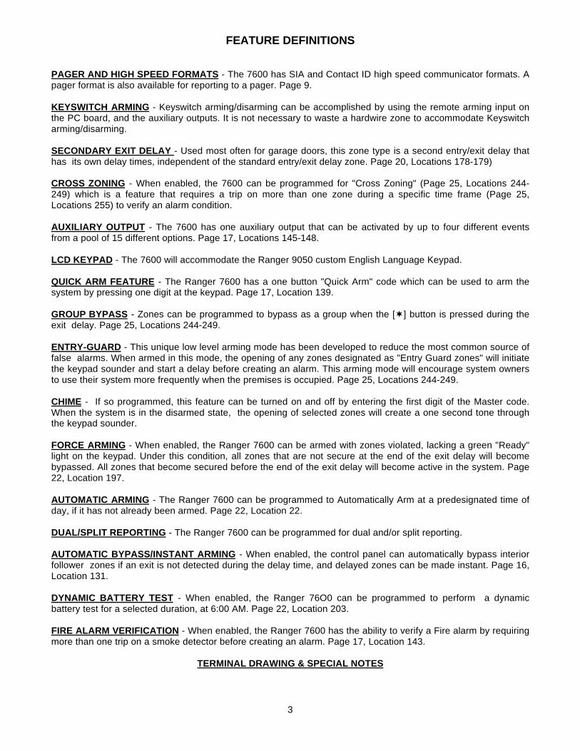
FEATURE DEFINITIONS
PAGER AND HIGH SPEED FORMATS - The 7600 has SIA and Contact ID high speed communicator formats. Apager format is also available for reporting to a pager. Page 9.
KEYSWITCH ARMING - Keyswitch arming/disarming can be accomplished by using the remote arming input onthe PC board, and the auxiliary outputs. It is not necessary to waste a hardwire zone to accommodate Keyswitcharming/disarming.
SECONDARY EXIT DELAY - Used most often for garage doors, this zone type is a second entry/exit delay thathas its own delay times, independent of the standard entry/exit delay zone. Page 20, Locations 178-179)
CROSS ZONING - When enabled, the 7600 can be programmed for "Cross Zoning" (Page 25, Locations 244-249) which is a feature that requires a trip on more than one zone during a specific time frame (Page 25,Locations 255) to verify an alarm condition.
AUXILIARY OUTPUT - The 7600 has one auxiliary output that can be activated by up to four different eventsfrom a pool of 15 different options. Page 17, Locations 145-148.
LCD KEYPAD - The 7600 will accommodate the Ranger 9050 custom English Language Keypad.
QUICK ARM FEATURE - The Ranger 7600 has a one button "Quick Arm" code which can be used to arm thesystem by pressing one digit at the keypad. Page 17, Location 139.
GROUP BYPASS - Zones can be programmed to bypass as a group when the [¬] button is pressed during theexit delay. Page 25, Locations 244-249.
ENTRY-GUARD - This unique low level arming mode has been developed to reduce the most common source offalse alarms. When armed in this mode, the opening of any zones designated as "Entry Guard zones" will initiatethe keypad sounder and start a delay before creating an alarm. This arming mode will encourage system ownersto use their system more frequently when the premises is occupied. Page 25, Locations 244-249.
CHIME - If so programmed, this feature can be turned on and off by entering the first digit of the Master code.When the system is in the disarmed state, the opening of selected zones will create a one second tone throughthe keypad sounder.
FORCE ARMING - When enabled, the Ranger 7600 can be armed with zones violated, lacking a green "Ready"light on the keypad. Under this condition, all zones that are not secure at the end of the exit delay will becomebypassed. All zones that become secured before the end of the exit delay will become active in the system. Page22, Location 197.
AUTOMATIC ARMING - The Ranger 7600 can be programmed to Automatically Arm at a predesignated time ofday, if it has not already been armed. Page 22, Location 22.
DUAL/SPLIT REPORTING - The Ranger 7600 can be programmed for dual and/or split reporting.
AUTOMATIC BYPASS/INSTANT ARMING - When enabled, the control panel can automatically bypass interiorfollower zones if an exit is not detected during the delay time, and delayed zones can be made instant. Page 16,Location 131.
DYNAMIC BATTERY TEST - When enabled, the Ranger 76O0 can be programmed to perform a dynamicbattery test for a selected duration, at 6:00 AM. Page 22, Location 203.
FIRE ALARM VERIFICATION - When enabled, the Ranger 7600 has the ability to verify a Fire alarm by requiringmore than one trip on a smoke detector before creating an alarm. Page 17, Location 143.
TERMINAL DRAWING & SPECIAL NOTES
4
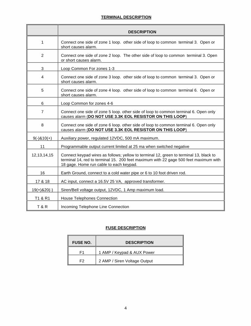
TERMINAL DESCRIPTION
DESCRIPTION
1 Connect one side of zone 1 loop. other side of loop to common terminal 3. Open orshort causes alarm.
2 Connect one side of zone 2 loop. The other side of loop to common terminal 3. Openor short causes alarm.
3 Loop Common For zones 1-3
4 Connect one side of zone 3 loop. other side of loop to common terminal 3. Open orshort causes alarm.
5 Connect one side of zone 4 loop. other side of loop to common terminal 6. Open orshort causes alarm.
6 Loop Common for zones 4-6
7 Connect one side of zone 5 loop. other side of loop to common terminal 6. Open onlycauses alarm (DO NOT USE 3.3K EOL RESISTOR ON THIS LOOP)
8 Connect one side of zone 6 loop. other side of loop to common terminal 6. Open onlycauses alarm (DO NOT USE 3.3K EOL RESISTOR ON THIS LOOP)
9(-)&10(+) Auxiliary power, regulated 12VDC, 500 mA maximum.
11 Programmable output current limited at 25 ma when switched negative
12,13,14,15 Connect keypad wires as follows; yellow to terminal 12, green to terminal 13, black toterminal 14, red to terminal 15. 200 feet maximum with 22 gage 500 feet maximum with18 gage. Home run cable to each keypad.
16 Earth Ground, connect to a cold water pipe or 6 to 10 foot driven rod.
17 & 18 AC input, connect a 16.5V 25 VA, approved transformer.
19(+)&20(-) Siren/Bell voltage output, 12VDC, 1 Amp maximum load.
T1 & R1 House Telephones Connection
T & R Incoming Telephone Line Connection
FUSE DESCRIPTION
FUSE NO. DESCRIPTION
F1 1 AMP / Keypad & AUX Power
F2 2 AMP / Siren Voltage Output

5
PROGRAMMING
The 7600 can be placed into the "Program" mode by use of the new 9075 Smart Programmer, or theoriginal 8950 programmer, or for Keypad programming, by utilizing the 9050 LCD Keypad (thepreferred method) or the 8601 LED Keypad. These methods are described below.
Using a Programmer
The 9075 Smart Programmer has been designed to make programming of the 7600 simpler as well asmore efficient for users. The 9075 programmer features up to 16 resident standard programs to allowfor separate system standardization. Plug the optional model 9075 programmer into the 4-pin maleoutlet marked "program" on the 7600 P.C. Board.
Using The LCD Keypad
The most straightforward method of Keypad programming is to utilize the 9050 LCD Keypad in theprogramming mode. To access the programming mode enter [C] [0] [0], followed by the four digit "GoTo Program" access code which is factory default [9] [0] [5] [0] (this code can be reprogrammed), andfollow the Keypad prompts. (See using the LED Keypad below.)
Using The LED Keypad
The 7600 can also be programmed by the standard binary method of Keypad programming describedbelow. When the 8601 LED Keypad is used for programming, enter the factory default four digit "Go ToProgram" access code of [9] [7] [1] [3]. NOTE: The 7600 must be disarmed to gain access toprogramming with this code. After entry of this code, the 7600 will be in the "Program" mode, and theyellow LED's will display the data in location 000. The data is displayed using a Binary system. Withthis system the yellow zone 1 LED equals "1" when illuminated. The zone 2 LED equals "2" whenilluminated. The zone 3 LED equals "4" when illuminated. The zone 4 LED equals "8" when illuminated.Thus if the data in location 000 is "9", the LED for zone 1 (=1) and zone 4 (=8) would be illuminated. Byadding the two values together, (1+8=9) you would determine that the data in location 000 is "9". If thedata in location 000 is "6", the LEDs for zone 2 (=2) and zone 3 (=4) would be added (2+4=6) indicatingthe data in that location to be "6". If no LED's are illuminated, the location contains a "0". To advancefrom location 000 through 255, press the [#] key. To go to a specific location, press the location numberfollowed by the [#] key. The yellow LED's will then display the data in that location. Data is changed byentering a number 0 to 15 followed by [¬] (¬ = data enter). Review the examples in figure 1 on thefollowing page.
Important Function Codes
[9]-[1]-[0]-[#] When in the program mode, this function code can be used to write original factorydefault codes into the 7600.[9]-[3]-[0]-[#] This function code is used to exit the programming mode after it was accessed via theKeypad.

6
PROGRAMMING EXAMPLE - FIGURE 2
8950 PROGRAMMER - FIGURE 3
7
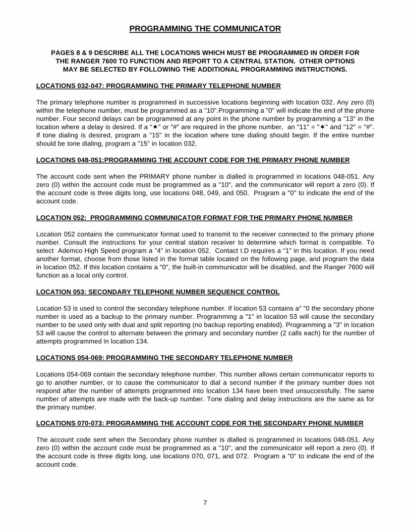
PROGRAMMING THE COMMUNICATOR
PAGES 8 & 9 DESCRIBE ALL THE LOCATIONS WHICH MUST BE PROGRAMMED IN ORDER FORTHE RANGER 7600 TO FUNCTION AND REPORT TO A CENTRAL STATION. OTHER OPTIONS
MAY BE SELECTED BY FOLLOWING THE ADDITIONAL PROGRAMMING INSTRUCTIONS.
LOCATIONS 032-047: PROGRAMMING THE PRIMARY TELEPHONE NUMBER
The primary telephone number is programmed in successive locations beginning with location 032. Any zero (0)within the telephone number, must be programmed as a "10".Programming a "0" will indicate the end of the phonenumber. Four second delays can be programmed at any point in the phone number by programming a "13" in thelocation where a delay is desired. If a "¬" or "#" are required in the phone number, an "11" = "¬" and "12" = "#".If tone dialing is desired, program a "15" in the location where tone dialing should begin. If the entire numbershould be tone dialing, program a "15" in location 032.
LOCATIONS 048-051:PROGRAMMING THE ACCOUNT CODE FOR THE PRIMARY PHONE NUMBER
The account code sent when the PRIMARY phone number is dialled is programmed in locations 048-051. Anyzero (0) within the account code must be programmed as a "10", and the communicator will report a zero (0). Ifthe account code is three digits long, use locations 048, 049, and 050. Program a "0" to indicate the end of theaccount code.
LOCATION 052: PROGRAMMING COMMUNICATOR FORMAT FOR THE PRIMARY PHONE NUMBER
Location 052 contains the communicator format used to transmit to the receiver connected to the primary phonenumber. Consult the instructions for your central station receiver to determine which format is compatible. Toselect Ademco High Speed program a "4" in location 052. Contact I.D requires a "1" in this location. If you needanother format, choose from those listed in the format table located on the following page, and program the datain location 052. If this location contains a "0", the built-in communicator will be disabled, and the Ranger 7600 willfunction as a local only control.
LOCATION 053: SECONDARY TELEPHONE NUMBER SEQUENCE CONTROL
Location 53 is used to control the secondary telephone number. If location 53 contains a" "0 the secondary phonenumber is used as a backup to the primary number. Programming a "1" in location 53 will cause the secondarynumber to be used only with dual and split reporting (no backup reporting enabled). Programming a "3" in location53 will cause the control to alternate between the primary and secondary number (2 calls each) for the number ofattempts programmed in location 134.
LOCATIONS 054-069: PROGRAMMING THE SECONDARY TELEPHONE NUMBER
Locations 054-069 contain the secondary telephone number. This number allows certain communicator reports togo to another number, or to cause the communicator to dial a second number if the primary number does notrespond after the number of attempts programmed into location 134 have been tried unsuccessfully. The samenumber of attempts are made with the back-up number. Tone dialing and delay instructions are the same as forthe primary number.
LOCATIONS 070-073: PROGRAMMING THE ACCOUNT CODE FOR THE SECONDARY PHONE NUMBER
The account code sent when the Secondary phone number is dialled is programmed in locations 048-051. Anyzero (0) within the account code must be programmed as a "10", and the communicator will report a zero (0). Ifthe account code is three digits long, use locations 070, 071, and 072. Program a "0" to indicate the end of theaccount code.
8
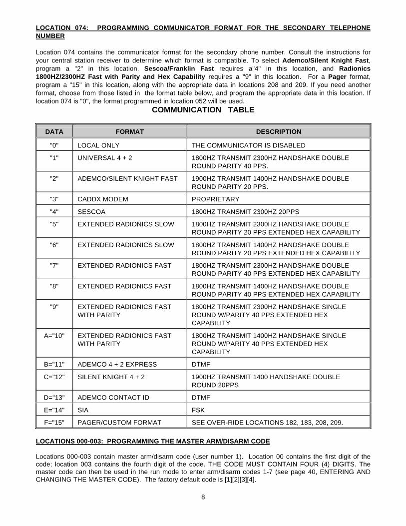
LOCATION 074: PROGRAMMING COMMUNICATOR FORMAT FOR THE SECONDARY TELEPHONENUMBER
Location 074 contains the communicator format for the secondary phone number. Consult the instructions foryour central station receiver to determine which format is compatible. To select Ademco/Silent Knight Fast,program a "2" in this location. Sescoa/Franklin Fast requires a"4" in this location, and Radionics1800HZ/2300HZ Fast with Parity and Hex Capability requires a "9" in this location. For a Pager format,program a "15" in this location, along with the appropriate data in locations 208 and 209. If you need anotherformat, choose from those listed in the format table below, and program the appropriate data in this location. Iflocation 074 is "0", the format programmed in location 052 will be used.
COMMUNICATION TABLE
DATA FORMAT DESCRIPTION
"0" LOCAL ONLY THE COMMUNICATOR IS DISABLED
"1" UNIVERSAL 4 + 2 1800HZ TRANSMIT 2300HZ HANDSHAKE DOUBLEROUND PARITY 40 PPS.
"2" ADEMCO/SILENT KNIGHT FAST 1900HZ TRANSMIT 1400HZ HANDSHAKE DOUBLEROUND PARITY 20 PPS.
"3" CADDX MODEM PROPRIETARY
"4" SESCOA 1800HZ TRANSMIT 2300HZ 20PPS
"5" EXTENDED RADIONICS SLOW 1800HZ TRANSMIT 2300HZ HANDSHAKE DOUBLEROUND PARITY 20 PPS EXTENDED HEX CAPABILITY
"6" EXTENDED RADIONICS SLOW 1800HZ TRANSMIT 1400HZ HANDSHAKE DOUBLEROUND PARITY 20 PPS EXTENDED HEX CAPABILITY
"7" EXTENDED RADIONICS FAST 1800HZ TRANSMIT 2300HZ HANDSHAKE DOUBLEROUND PARITY 40 PPS EXTENDED HEX CAPABILITY
"8" EXTENDED RADIONICS FAST 1800HZ TRANSMIT 1400HZ HANDSHAKE DOUBLEROUND PARITY 40 PPS EXTENDED HEX CAPABILITY
"9" EXTENDED RADIONICS FASTWITH PARITY
1800HZ TRANSMIT 2300HZ HANDSHAKE SINGLEROUND W/PARITY 40 PPS EXTENDED HEXCAPABILITY
A="10" EXTENDED RADIONICS FASTWITH PARITY
1800HZ TRANSMIT 1400HZ HANDSHAKE SINGLEROUND W/PARITY 40 PPS EXTENDED HEXCAPABILITY
B="11" ADEMCO 4 + 2 EXPRESS DTMF
C="12" SILENT KNIGHT 4 + 2 1900HZ TRANSMIT 1400 HANDSHAKE DOUBLEROUND 20PPS
D="13" ADEMCO CONTACT ID DTMF
E="14" SIA FSK
F="15" PAGER/CUSTOM FORMAT SEE OVER-RIDE LOCATIONS 182, 183, 208, 209.
LOCATIONS 000-003: PROGRAMMING THE MASTER ARM/DISARM CODE
Locations 000-003 contain master arm/disarm code (user number 1). Location 00 contains the first digit of thecode; location 003 contains the fourth digit of the code. THE CODE MUST CONTAIN FOUR (4) DIGITS. Themaster code can then be used in the run mode to enter arm/disarm codes 1-7 (see page 40, ENTERING ANDCHANGING THE MASTER CODE). The factory default code is [1][2][3][4].
9
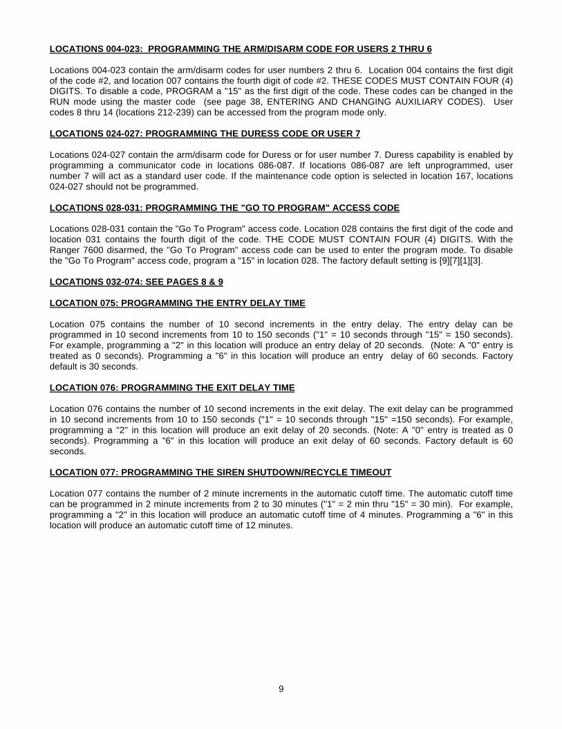
LOCATIONS 004-023: PROGRAMMING THE ARM/DISARM CODE FOR USERS 2 THRU 6
Locations 004-023 contain the arm/disarm codes for user numbers 2 thru 6. Location 004 contains the first digitof the code #2, and location 007 contains the fourth digit of code #2. THESE CODES MUST CONTAIN FOUR (4)DIGITS. To disable a code, PROGRAM a "15" as the first digit of the code. These codes can be changed in theRUN mode using the master code (see page 38, ENTERING AND CHANGING AUXILIARY CODES). Usercodes 8 thru 14 (locations 212-239) can be accessed from the program mode only.
LOCATIONS 024-027: PROGRAMMING THE DURESS CODE OR USER 7
Locations 024-027 contain the arm/disarm code for Duress or for user number 7. Duress capability is enabled byprogramming a communicator code in locations 086-087. If locations 086-087 are left unprogrammed, usernumber 7 will act as a standard user code. If the maintenance code option is selected in location 167, locations024-027 should not be programmed.
LOCATIONS 028-031: PROGRAMMING THE "GO TO PROGRAM" ACCESS CODE
Locations 028-031 contain the "Go To Program" access code. Location 028 contains the first digit of the code andlocation 031 contains the fourth digit of the code. THE CODE MUST CONTAIN FOUR (4) DIGITS. With theRanger 7600 disarmed, the "Go To Program" access code can be used to enter the program mode. To disablethe "Go To Program" access code, program a "15" in location 028. The factory default setting is [9][7][1][3].
LOCATIONS 032-074: SEE PAGES 8 & 9
LOCATION 075: PROGRAMMING THE ENTRY DELAY TIME
Location 075 contains the number of 10 second increments in the entry delay. The entry delay can beprogrammed in 10 second increments from 10 to 150 seconds ("1" = 10 seconds through "15" = 150 seconds).For example, programming a "2" in this location will produce an entry delay of 20 seconds. (Note: A "0" entry istreated as 0 seconds). Programming a "6" in this location will produce an entry delay of 60 seconds. Factorydefault is 30 seconds.
LOCATION 076: PROGRAMMING THE EXIT DELAY TIME
Location 076 contains the number of 10 second increments in the exit delay. The exit delay can be programmedin 10 second increments from 10 to 150 seconds ("1" = 10 seconds through "15" =150 seconds). For example,programming a "2" in this location will produce an exit delay of 20 seconds. (Note: A "0" entry is treated as 0seconds). Programming a "6" in this location will produce an exit delay of 60 seconds. Factory default is 60seconds.
LOCATION 077: PROGRAMMING THE SIREN SHUTDOWN/RECYCLE TIMEOUT
Location 077 contains the number of 2 minute increments in the automatic cutoff time. The automatic cutoff timecan be programmed in 2 minute increments from 2 to 30 minutes ("1" = 2 min thru "15" = 30 min). For example,programming a "2" in this location will produce an automatic cutoff time of 4 minutes. Programming a "6" in thislocation will produce an automatic cutoff time of 12 minutes.
10
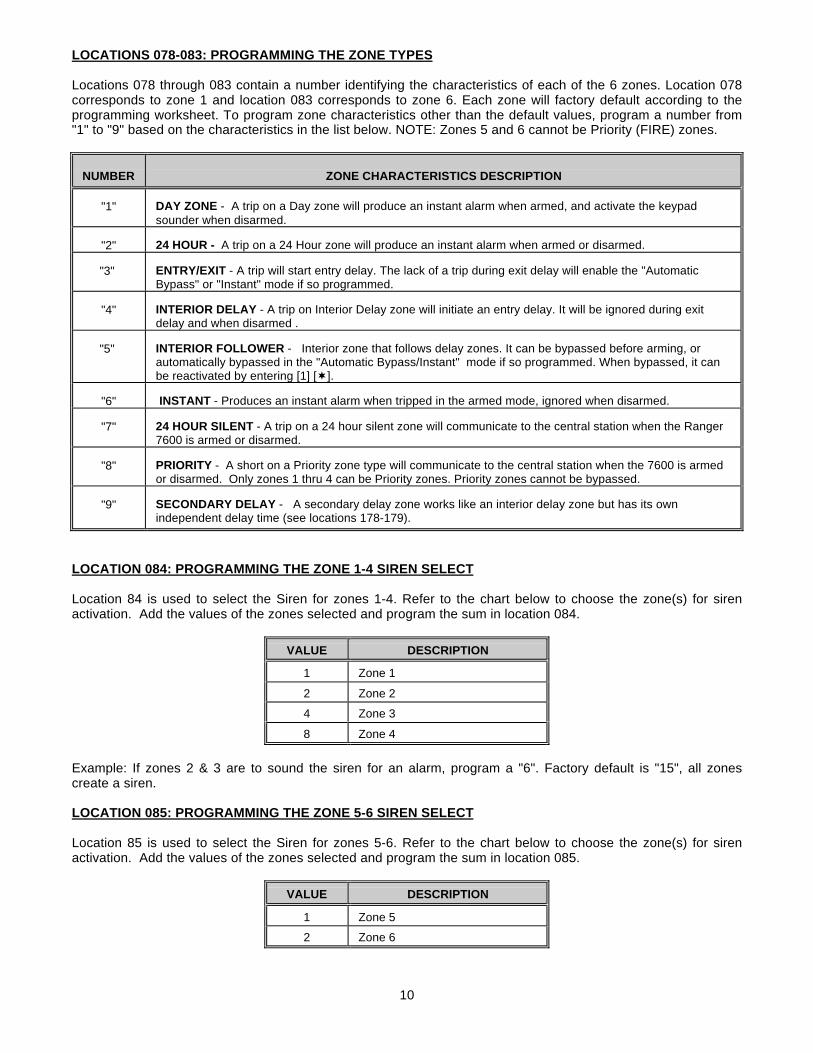
LOCATIONS 078-083: PROGRAMMING THE ZONE TYPES
Locations 078 through 083 contain a number identifying the characteristics of each of the 6 zones. Location 078corresponds to zone 1 and location 083 corresponds to zone 6. Each zone will factory default according to theprogramming worksheet. To program zone characteristics other than the default values, program a number from"1" to "9" based on the characteristics in the list below. NOTE: Zones 5 and 6 cannot be Priority (FIRE) zones.
NUMBER ZONE CHARACTERISTICS DESCRIPTION
"1" DAY ZONE - A trip on a Day zone will produce an instant alarm when armed, and activate the keypadsounder when disarmed.
"2" 24 HOUR - A trip on a 24 Hour zone will produce an instant alarm when armed or disarmed.
"3" ENTRY/EXIT - A trip will start entry delay. The lack of a trip during exit delay will enable the "AutomaticBypass" or "Instant" mode if so programmed.
"4" INTERIOR DELAY - A trip on Interior Delay zone will initiate an entry delay. It will be ignored during exitdelay and when disarmed .
"5" INTERIOR FOLLOWER - Interior zone that follows delay zones. It can be bypassed before arming, orautomatically bypassed in the "Automatic Bypass/Instant" mode if so programmed. When bypassed, it canbe reactivated by entering [1] [¬].
"6" INSTANT - Produces an instant alarm when tripped in the armed mode, ignored when disarmed.
"7" 24 HOUR SILENT - A trip on a 24 hour silent zone will communicate to the central station when the Ranger7600 is armed or disarmed.
"8" PRIORITY - A short on a Priority zone type will communicate to the central station when the 7600 is armedor disarmed. Only zones 1 thru 4 can be Priority zones. Priority zones cannot be bypassed.
"9" SECONDARY DELAY - A secondary delay zone works like an interior delay zone but has its ownindependent delay time (see locations 178-179).
LOCATION 084: PROGRAMMING THE ZONE 1-4 SIREN SELECT
Location 84 is used to select the Siren for zones 1-4. Refer to the chart below to choose the zone(s) for sirenactivation. Add the values of the zones selected and program the sum in location 084.
VALUE DESCRIPTION
1 Zone 1
2 Zone 2
4 Zone 3
8 Zone 4
Example: If zones 2 & 3 are to sound the siren for an alarm, program a "6". Factory default is "15", all zonescreate a siren.
LOCATION 085: PROGRAMMING THE ZONE 5-6 SIREN SELECT
Location 85 is used to select the Siren for zones 5-6. Refer to the chart below to choose the zone(s) for sirenactivation. Add the values of the zones selected and program the sum in location 085.
VALUE DESCRIPTION
1 Zone 5
2 Zone 6
11
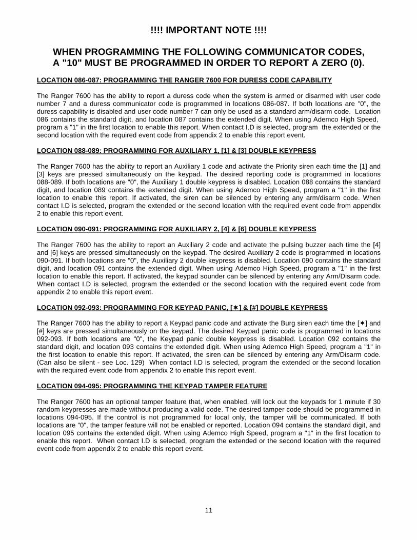
!!!! IMPORTANT NOTE !!!!
WHEN PROGRAMMING THE FOLLOWING COMMUNICATOR CODES, A "10" MUST BE PROGRAMMED IN ORDER TO REPORT A ZERO (0).
LOCATION 086-087: PROGRAMMING THE RANGER 7600 FOR DURESS CODE CAPABILITY
The Ranger 7600 has the ability to report a duress code when the system is armed or disarmed with user codenumber 7 and a duress communicator code is programmed in locations 086-087. If both locations are "0", theduress capability is disabled and user code number 7 can only be used as a standard arm/disarm code. Location086 contains the standard digit, and location 087 contains the extended digit. When using Ademco High Speed, program a "1" in the first location to enable this report. When contact I.D is selected, program the extended or thesecond location with the required event code from appendix 2 to enable this report event.
LOCATION 088-089: PROGRAMMING FOR AUXILIARY 1, [1] & [3] DOUBLE KEYPRESS
The Ranger 7600 has the ability to report an Auxiliary 1 code and activate the Priority siren each time the [1] and[3] keys are pressed simultaneously on the keypad. The desired reporting code is programmed in locations088-089. If both locations are "0", the Auxiliary 1 double keypress is disabled. Location 088 contains the standarddigit, and location 089 contains the extended digit. When using Ademco High Speed, program a "1" in the firstlocation to enable this report. If activated, the siren can be silenced by entering any arm/disarm code. Whencontact I.D is selected, program the extended or the second location with the required event code from appendix2 to enable this report event.
LOCATION 090-091: PROGRAMMING FOR AUXILIARY 2, [4] & [6] DOUBLE KEYPRESS
The Ranger 7600 has the ability to report an Auxiliary 2 code and activate the pulsing buzzer each time the [4]and [6] keys are pressed simultaneously on the keypad. The desired Auxiliary 2 code is programmed in locations090-091. If both locations are "0", the Auxiliary 2 double keypress is disabled. Location 090 contains the standarddigit, and location 091 contains the extended digit. When using Ademco High Speed, program a "1" in the firstlocation to enable this report. If activated, the keypad sounder can be silenced by entering any Arm/Disarm code.When contact I.D is selected, program the extended or the second location with the required event code fromappendix 2 to enable this report event.
LOCATION 092-093: PROGRAMMING FOR KEYPAD PANIC, [¬¬] & [#] DOUBLE KEYPRESS
The Ranger 7600 has the ability to report a Keypad panic code and activate the Burg siren each time the [¬] and[#] keys are pressed simultaneously on the keypad. The desired Keypad panic code is programmed in locations092-093. If both locations are "0", the Keypad panic double keypress is disabled. Location 092 contains thestandard digit, and location 093 contains the extended digit. When using Ademco High Speed, program a "1" inthe first location to enable this report. If activated, the siren can be silenced by entering any Arm/Disarm code.(Can also be silent - see Loc. 129) When contact I.D is selected, program the extended or the second locationwith the required event code from appendix 2 to enable this report event.
LOCATION 094-095: PROGRAMMING THE KEYPAD TAMPER FEATURE
The Ranger 7600 has an optional tamper feature that, when enabled, will lock out the keypads for 1 minute if 30random keypresses are made without producing a valid code. The desired tamper code should be programmed inlocations 094-095. If the control is not programmed for local only, the tamper will be communicated. If bothlocations are "0", the tamper feature will not be enabled or reported. Location 094 contains the standard digit, andlocation 095 contains the extended digit. When using Ademco High Speed, program a "1" in the first location toenable this report. When contact I.D is selected, program the extended or the second location with the requiredevent code from appendix 2 to enable this report event.
12
LOCATION 096-097: PROGRAMMING TO REPORT DOWNLOADING COMPLETE
Locations 096-097 contain the communicator report sent each time a download session has been completed. Thereport will come in after a disconnect has been made from a downloading session. Location 096 contains thestandard communicator code, and location 097 contains the extended communicator code. When using AdemcoHigh Speed, program a "1" in the first location to enable this report. If locations 096-097 are "0", this report isdisabled. When contact I.D is selected, program the extended or the second location with the required event codefrom appendix 2 to enable this report event.
LOCATION 098-099: PROGRAMMING FOR AUTOTEST REPORTS
The Ranger 7600 has the ability to send autotest reports at intervals from 1 to 15 days. Locations 098-099 containthe communicator codes sent for autotest. Location 098 contains the standard communicator code, and location099 contains the extended code. When using Ademco High Speed, program a "1" in the first location to enablethis report. If locations 098-099 are "0", autotest is disabled. When contact I.D is selected, program theextended, or second location with the required event code from appendix 2 to enable this report.
(NOTE: WHEN USING AUTOTEST, LOCATIONS 152-166 MUST BE PROGRAMMED.)
LOCATION 100-101: PROGRAMMING THE 7600 TO REPORT FAIL TO COMMUNICATE
The 7600 has the ability to send a failure to communicate report each time communication is re-established aftera signal has been unable the report. The data that failed to communicate will not be sent but it can be recoveredfrom the log. The desired Fail to communicate code is programmed in locations 100-101. If both locations are "0",Fail to Communicate will not be reported. Location 100 contains the standard digit, and location 101 contains theextended digit. When using 4+2 format, the number programmed in location 100 is sent as the second or "ones"digit. The first or "tens" digit is programmed in location 101.
LOCATION 102: PROGRAMMING TO REPORT CLOSING
The Ranger 7600 has the ability to report a closing code each time the control is armed. Program a "1" in thislocation to enable this report. If this location contains a "0", closing will not be reported. When using a one button"Quick Arm" code the man number is 1. The closing report will not be initiated until the end of the exit delay.
LOCATION 103: PROGRAMMING TO REPORT OPENINGS
The Ranger 7600 has the ability to report an opening code each time the control is disarmed. Program a "1" inthis location to enable this report. If this location contains "0", openings will not be reported. When using theremote arming input, the man number is 1.
LOCATION 104-105: PROGRAMMING THE COMMUNICATOR CODE FOR ZONE 1
Locations 104-105 contain the communicator code to be reported each time zone 1 creates an alarm. Location104 contains the standard digit, and location 105 contains the extended digit. When using Ademco High Speed,program a "1" in the first location to enable this report.
LOCATION 106-107: PROGRAMMING THE COMMUNICATOR CODE FOR ZONE 2
Locations 106-107 contain the communicator code to be reported each time zone 2 creates an alarm. Location106 contains the standard digit, and location 107 contains the extended digit. When using Ademco High Speed,program a "1" in the first location to enable this report.
LOCATION 108-109: PROGRAMMING THE COMMUNICATOR CODE FOR ZONE 3
Locations 108-109 contain the communicator code to be reported each time zone 3 creates an alarm. Location108 contains the standard digit, and location 109 contains the extended digit. When using Ademco High Speed,program a "1" in the first location to enable this report.
13
LOCATION 110-111: PROGRAMMING THE COMMUNICATOR CODE FOR ZONE 4
Locations 110-111 contain the communicator code to be reported each time zone 4 creates an alarm. Location110 contains the standard digit, and location 111 contains the extended digit. When using Ademco High Speed,program a "1" in the first location to enable this report.
LOCATION 112-113: PROGRAMMING THE COMMUNICATOR CODE FOR ZONE 5
Locations 112-113 contain the communicator code to be reported each time zone 5 creates an alarm. Location112 contains the standard digit, and location 113 contains the extended digit. When using Ademco High Speed,program a "1" in the first location to enable this report.
LOCATION 114-115: PROGRAMMING THE COMMUNICATOR CODE FOR ZONE 6
Locations 114-115 contain the communicator code to be reported each time zone 6 creates an alarm. Location114 contains the standard digit, and location 115 contains the extended digit. When using Ademco High Speed,program a "1" in the first location to enable this report.
LOCATION 116-117: PROGRAMMING TO REPORT START OF TEST MODE
The Ranger 7600 has the ability to signal the central station that a test mode has begun. This test mode can beused to alert the central station not to dispatch alarms sent during the test. The test mode is entered bypressing[¬]-[9]-[0]-[#] (followed by the master code). Locations 116-117 contain the communicator code sentwhen the control is in the test mode. Location 116 contains the standard digit and location 117 contains theextended digit.
LOCATION 118-119: PROGRAMMING TO REPORT END OF TEST MODE
The 7600 has the ability to signal the central station that a test mode has ended. This test mode can be used toalert the central station to begin dispatch alarms again. The test mode is exited by pressing[¬]-[9]-[0]-[#] (followedby the master code). The test mode will automatically expire after 1 hour. Locations 118-119 contain thecommunicator code sent when the control exits the test mode. Location 118 contains the standard digit andlocation 119 contains the extended digit.
LOCATION 120-121: PROGRAMMING TO REPORT AC POWER LOSS
The Ranger 7600 has the ability to report an AC power failure code when AC power is lost. This report can beimmediate, or delayed depending on the information programmed in location 150 (AC POWER LOSS DELAY).The desired AC failure mode should be programmed in locations 120-121. If both locations are "0", AC powerfailures will not be reported. Location 120 contains the standard digit, and location 121 contains the extendeddigit. When using Ademco High Speed, program a "1" in the first location to enable this report. When contact I.Dis selected, program the extended or the second location with the required event code from appendix 2 to enablethis report event.
LOCATION 122-123: PROGRAMMING TO REPORT LOW BATTERY
The Ranger 7600 has the ability to report a low battery code when AC power has been lost and the battery hasdischarged down to 10.3 volts. The desired low battery code is programmed in locations 122-123. If both locationsare "0", low battery will not be reported. Location 122 contains the standard digit, and, location 123 contains theextended digit. When using Ademco High Speed, program a "1" in the first location to enable this report. Whencontact I.D is selected, program the extended or the second location with the required event code from appendix2 to enable this report event.
LOCATION 124: PROGRAMMING FOR PRIORITY ZONE TROUBLE REPORTING
The Ranger 7600 has the ability to report a trouble code each time a Priority zone opens. The desired troublecode is programmed in location 124. If this location contains a "0", the Priority Trouble will not be reported. Whenusing Ademco High Speed, program a "1" in this location to enable this report. When contact I.D is selected,program the extended or the second location with the required event code from appendix 2 to enable this reportevent.
14
LOCATION 125: PROGRAMMING FOR ZONE BYPASS REPORTING
The Ranger 7600 has the ability to report a bypass on zones 1-6. The desired bypass code is programmed inlocation 125. If this location contains a "0", zone bypass will not be reported. When using 4+2 format, the numberprogrammed in this location is sent as the first, or "tens" digit. The second, or "ones" digit is the zonecommunicator code. The bypass will be reported at the end of the exit delay for non-24 hour zones. 24 hourzones will report a bypass immediately. When a bypass is removed, a restore will be reported if "Restore" isenabled in location 126. When using Ademco High Speed, program a "1" in this location to enable this report.
LOCATION 126: PROGRAMMING THE COMMUNICATOR CODE FOR RESTORAL
Location 126 contains the communicator code that will be sent for restoral of a zone. If this location contains a "0",no restorals will be reported. If a restoral code is programmed and an extended format is selected, the restoralswill be reported by zone. If a restoral code is programmed and an extended format is not selected, a restoral codewill be sent when all of the previously reported conditions have restored. When using Ademco High Speed,program a "1" in this location to enable this report.
LOCATION 127: PROGRAMMING THE COMMUNICATOR CODE FOR CANCEL (EXCEPTION OPENING)
Location 127 contains the communicator code that will be sent for cancel. The cancel code programmed in thislocation will be sent if an arm/disarm code is entered after a trip on zones 1 through 6 has been reported(excluding 24 hour zones). After a cancel has been reported, no loop restorals will be transmitted on non-24 Hourzones. If this location contains a "0", cancel is disabled. When using Ademco High Speed, program a "1" in thislocation to enable this report.
LOCATION 128: PROGRAMMING DELAY BEFORE DIAL TIME
Location 128 is used to enable the communicator abort. The number programmed in location 128 is the numberof 2 second increments the communicator will delay before dial of a burglary alarm. If an arm/disarm code isentered during this delay the 7600 will abort the transmission. If this location contains a "0", the Ranger 7600 willnot abort any reports.
LOCATION 129: PROGRAMMING FOR SILENT PANIC/HOLD-UP
Location 129 is used to silence the audible output for a panic/hold-up alarm. Programming a "1" in this locationwill silence the audible output during a panic/hold-up alarm. If this location contains a "0", the Ranger 7600 willhave an audible panic/hold-up output.
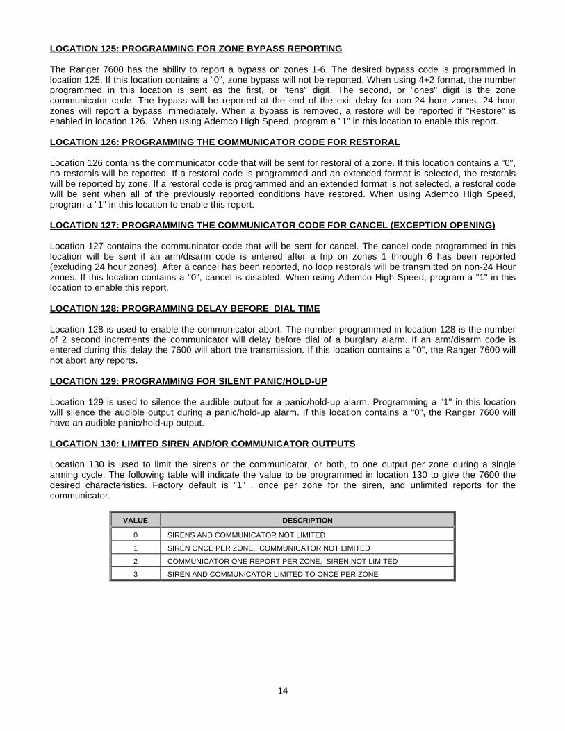
LOCATION 130: LIMITED SIREN AND/OR COMMUNICATOR OUTPUTS
Location 130 is used to limit the sirens or the communicator, or both, to one output per zone during a singlearming cycle. The following table will indicate the value to be programmed in location 130 to give the 7600 thedesired characteristics. Factory default is "1" , once per zone for the siren, and unlimited reports for thecommunicator.
VALUE DESCRIPTION
0 SIRENS AND COMMUNICATOR NOT LIMITED
1 SIREN ONCE PER ZONE, COMMUNICATOR NOT LIMITED
2 COMMUNICATOR ONE REPORT PER ZONE, SIREN NOT LIMITED
3 SIREN AND COMMUNICATOR LIMITED TO ONCE PER ZONE
15
LOCATION 131: AUTOMATIC BYPASS / INSTANT ARMING
Location 131 is used to enable automatic "Instant Arming". Programming a "1" in this location will cause thecontrol to automatically enter the "Instant" mode and bypass interior follower zones if a fault is not detected on anentry/exit zone during the exit delay. Programming a "3" in this location (Automatic Bypass), will cause the interiorfollower zones to become bypassed if a fault is not detected on an entry/exit zone, yet will not change the statusof the entry/exit zone. If this location contains a "0", these features are disabled. Pressing the [¬] key when thesystem is armed, will cause the "Instant" light to toggle. When the "Instant" light is on, the entry/exit zone isinstant; when off, the entry/exit zone is delayed. The [¬] key will toggle the "Instant" mode regardless of theprogramming data in this location. When the system is armed, bypassed interior follower zones can bereactivated by entering [first digit of master code] followed by [¬]. Once the interior is reactivated they cannot bebypassed again without disarming the control.
LOCATION 132: ENABLE KEYPAD SIREN SOUNDER
The built-in keypad siren of the 8001 is enabled in location 132. program a "1" in location 132 to enable.
LOCATION 133: L.E.D. EXTINGUISH FEATURE
Keypad LEDs (with the exception of the A.C. LED) will be extinguished after 60 seconds of keypad inactivity, if a"1" is programmed in location 133. The LEDs will become illuminated immediately upon a keypress or alarmcondition.
LOCATION 134: ENTERING THE NUMBER OF DIAL ATTEMPTS
Location 134 is used to enter the number of dial attempts (1 to 15 attempts) the communicator will try for theappropriate phone number(s) before ending the notification process. If this location contains an "8", thecommunicator will make 8 attempts to the first number, and then eight attempts to a second number, if a secondnumber is programmed as backup.
LOCATION 135: POWER UP CONDITION
If a "1" is programmed in location 135, the Ranger 7600 will power-up disarmed if there is a total power shutdownand battery failure. If a "2" is programmed in this location, it will power up armed. If this location contains a "0", theRanger 7600 will maintain the condition it was in at power down. A watchdog circuit reset will cause the Ranger7600 to reset to the selected condition.
LOCATION 136: POWER UP DELAY
If a one "1" is programmed in location 136, the Ranger 7600 will not delay 60 seconds before accepting open orshort inputs from any zone. If a "0" is programmed, sensors on all zones are allowed 60 seconds to stabilize atpower-up, or after exiting the program mode. After 60 seconds, the Ranger will once again accept loop opens orshorts as an alarm condition. This 60 second period will also be initiated after a watchdog circuit reset condition.
LOCATION 137: IMMEDIATE RESTORE BY ZONE
If a "1" is programmed in location 137, restoral signals will follow the restore condition and report restoresimmediately after the condition has unfaulted. A non-extended format will not send a restore message until allzones and trouble conditions have restored. If this location contains a "0", the restore signal or signals will bereported only after siren timeout.
LOCATION 138: NO ARMING WITH A ZONE BYPASSED
If a "1" is programmed in location 138, the Ranger 7600 will not arm with any zone bypassed.
16
LOCATION 139: ENABLING QUICK ARM
The Ranger 7600 can be programmed to "Quick Arm" with the 3 key by programming a "1" in location 139. A "0"in this location will disable this feature. If the "Quick Arm" digit is the same as the first digit of the "Go To ProgramCode", the "Quick Arm" code will not function.
LOCATION 140: RESERVED FOR FUTURE USE
LOCATION 141: PROGRAMMING LOCAL SYSTEM FUNCTIONS
Location 141 is used to enable the exit warning tone and the missing battery test. The exit warning tone sounds along beep followed by 3 short beeps, 10 seconds before the exit delay expires. To enable the exit warning,program a "1" in location 141. Location 141 is also used to enable the missing battery test. When enabled thisfeature will cause the system to test the standby battery once every 40 seconds to see if it is present. If it is not, alow battery will be detected. To enable missing battery detection program a "2" in location 141. To enable bothexit warning and missing battery detection program a "3".
LOCATION 142: SIREN/BELL TEST FEATURE
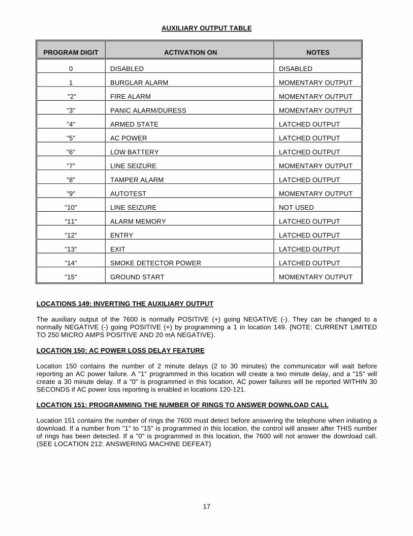
The siren/bell can be programmed to activate upon different conditions. Using the chart below, add the values ofthe desired condition(s) and program the sum of those values in location 142. When the siren/bell is activated bypressing the [1] and [7] keys simultaneously, the communicator will not report a message, the siren/bell will beactivated and a 1 minute battery test will begin. The bell/siren can be silenced by entering an arm/disarm code.
VALUE DESCRIPTION
1 Activation by pressing [1] and [7] keys simultaneously
2 Momentary activation at arming
4 Momentary at end of exit delay
8 Momentary at kiss off ringback
LOCATION 143: SMOKE POWER RESET AND/OR FIRE ALARM VERIFICATION
Programming a "1" in location 143 will cause the 7600 (when in the disarmed state) to interrupt the smokedetector power each time the [#] button is pressed. If this location contains a "0", the smoke detector power willreset only after the [#] button is pressed when the corresponding LED(s) for zones designated as "Priority" are onsteady for alarm or blinking for trouble. Programming a "2" in this location will enable the "Fire Alarm Verification"feature. When the "Fire Alarm Verification" feature is enabled, a smoke detector will be powered down and resetautomatically after the first trip, waiting for a second trip within a 30 minute time frame (thus verifying a fire alarmcondition) before creating an alarm and communicating a message.
LOCATION 144: RESERVED FOR FUTURE USE
LOCATION 145-148: PROGRAMMING THE AUXILIARY OUTPUT
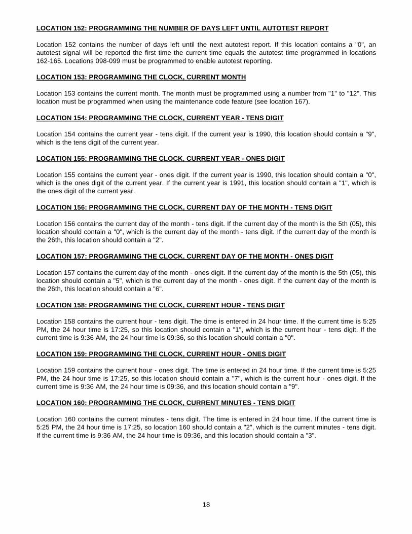
The 7600 has one auxiliary output located on terminal 11 on the control PC board. This output can be activatedby four different conditions selected from the 15 options in the following table. To utilize this output, programlocations 145-148 with a number from "0" to "14" in accordance with the desired characteristics listed below. Theoutput will trigger for any of the activations programmed in any of these locations.
17
AUXILIARY OUTPUT TABLE
PROGRAM DIGIT ACTIVATION ON NOTES
0 DISABLED DISABLED
1 BURGLAR ALARM MOMENTARY OUTPUT
"2" FIRE ALARM MOMENTARY OUTPUT
"3" PANIC ALARM/DURESS MOMENTARY OUTPUT
"4" ARMED STATE LATCHED OUTPUT
"5" AC POWER LATCHED OUTPUT
"6" LOW BATTERY LATCHED OUTPUT
"7" LINE SEIZURE MOMENTARY OUTPUT
"8" TAMPER ALARM LATCHED OUTPUT
"9" AUTOTEST MOMENTARY OUTPUT
"10" LINE SEIZURE NOT USED
"11" ALARM MEMORY LATCHED OUTPUT
"12" ENTRY LATCHED OUTPUT
"13" EXIT LATCHED OUTPUT
"14" SMOKE DETECTOR POWER LATCHED OUTPUT
"15" GROUND START MOMENTARY OUTPUT
LOCATIONS 149: INVERTING THE AUXILIARY OUTPUT
The auxiliary output of the 7600 is normally POSITIVE (+) going NEGATIVE (-). They can be changed to anormally NEGATIVE (-) going POSITIVE (+) by programming a 1 in location 149. {NOTE: CURRENT LIMITEDTO 250 MICRO AMPS POSITIVE AND 20 mA NEGATIVE).
LOCATION 150: AC POWER LOSS DELAY FEATURE
Location 150 contains the number of 2 minute delays (2 to 30 minutes) the communicator will wait beforereporting an AC power failure. A "1" programmed in this location will create a two minute delay, and a "15" willcreate a 30 minute delay. If a "0" is programmed in this location, AC power failures will be reported WITHIN 30SECONDS if AC power loss reporting is enabled in locations 120-121.
LOCATION 151: PROGRAMMING THE NUMBER OF RINGS TO ANSWER DOWNLOAD CALL
Location 151 contains the number of rings the 7600 must detect before answering the telephone when initiating adownload. If a number from "1" to "15" is programmed in this location, the control will answer after THIS numberof rings has been detected. If a "0" is programmed in this location, the 7600 will not answer the download call.(SEE LOCATION 212: ANSWERING MACHINE DEFEAT)
18
LOCATION 152: PROGRAMMING THE NUMBER OF DAYS LEFT UNTIL AUTOTEST REPORT
Location 152 contains the number of days left until the next autotest report. If this location contains a "0", anautotest signal will be reported the first time the current time equals the autotest time programmed in locations162-165. Locations 098-099 must be programmed to enable autotest reporting.
LOCATION 153: PROGRAMMING THE CLOCK, CURRENT MONTH
Location 153 contains the current month. The month must be programmed using a number from "1" to "12". Thislocation must be programmed when using the maintenance code feature (see location 167).
LOCATION 154: PROGRAMMING THE CLOCK, CURRENT YEAR - TENS DIGIT
Location 154 contains the current year - tens digit. If the current year is 1990, this location should contain a "9",which is the tens digit of the current year.
LOCATION 155: PROGRAMMING THE CLOCK, CURRENT YEAR - ONES DIGIT
Location 155 contains the current year - ones digit. If the current year is 1990, this location should contain a "0",which is the ones digit of the current year. If the current year is 1991, this location should contain a "1", which isthe ones digit of the current year.
LOCATION 156: PROGRAMMING THE CLOCK, CURRENT DAY OF THE MONTH - TENS DIGIT
Location 156 contains the current day of the month - tens digit. If the current day of the month is the 5th (05), thislocation should contain a "0", which is the current day of the month - tens digit. If the current day of the month isthe 26th, this location should contain a "2".
LOCATION 157: PROGRAMMING THE CLOCK, CURRENT DAY OF THE MONTH - ONES DIGIT
Location 157 contains the current day of the month - ones digit. If the current day of the month is the 5th (05), thislocation should contain a "5", which is the current day of the month - ones digit. If the current day of the month isthe 26th, this location should contain a "6".
LOCATION 158: PROGRAMMING THE CLOCK, CURRENT HOUR - TENS DIGIT
Location 158 contains the current hour - tens digit. The time is entered in 24 hour time. If the current time is 5:25PM, the 24 hour time is 17:25, so this location should contain a "1", which is the current hour - tens digit. If thecurrent time is 9:36 AM, the 24 hour time is 09:36, so this location should contain a "0".
LOCATION 159: PROGRAMMING THE CLOCK, CURRENT HOUR - ONES DIGIT
Location 159 contains the current hour - ones digit. The time is entered in 24 hour time. If the current time is 5:25PM, the 24 hour time is 17:25, so this location should contain a "7", which is the current hour - ones digit. If thecurrent time is 9:36 AM, the 24 hour time is 09:36, and this location should contain a "9".
LOCATION 160: PROGRAMMING THE CLOCK, CURRENT MINUTES - TENS DIGIT
Location 160 contains the current minutes - tens digit. The time is entered in 24 hour time. If the current time is5:25 PM, the 24 hour time is 17:25, so location 160 should contain a "2", which is the current minutes - tens digit.If the current time is 9:36 AM, the 24 hour time is 09:36, and this location should contain a "3".
19
LOCATION 161: PROGRAMMING THE CLOCK, CURRENT MINUTES - ONES DIGIT
Location 161 contains the current minutes - ones digit. The time is entered in 24 hour time. If the current time is5:25 PM, the 24 hour time is 17:25, so this location should contain a "5", which is the current minutes - ones digit.If the current time is 9:36 AM, the 24 hour time is 09:36, and this location should contain a "6".
LOCATION 162: PROGRAMMING THE AUTOTEST TIME, HOUR - TENS DIGIT
Location 162 contains the tens digit of the hour that the autotest report is initiated. The time is entered in 24 hourtime. If the desired autotest time is 5:25 PM, the 24 hour time is 17:25, so this location should contain a "1", whichis the tens digit of the desired hour for autotest. If the desired autotest time is 9:36 AM, the 24 hour time is 09:36,and this location should contain a "0".
LOCATION 163: PROGRAMMING THE AUTOTEST TIME, HOUR - ONES DIGIT
Location 163 contains the ones digit of the hour that the autotest report is desired. The time is entered in 24 hourtime. If the desired autotest time is 5:25 PM, the 24 hour time is 17:25, so this location should contain a "7", whichis the ones digit of the hour for autotest. If the desired autotest time is 9:36 AM, the 24 hour time is 09:36, and thislocation should contain a "9".
LOCATION 164: PROGRAMMING THE AUTOTEST TIME, MINUTES - TENS DIGIT
Location 164 contains the tens digit, of the minutes after the hour that the autotest is desired. The time is enteredin 24 hour time. If the desired autotest time is 5:25 PM, the 24 hour time is 17:25, so this location should contain a"2", which is the tens digit of the minutes for autotest time. If the desired autotest time is 9:36 AM, the 24 hourtime is 09:36, this location should contain a "3".
LOCATION 165: PROGRAMMING THE AUTOTEST TIME, MINUTES - ONES DIGIT
Location 165 contains the ones digit, of the minutes after the hour that the autotest is desired. The time is enteredin 24 hour time. If the desired autotest time is 5:25 PM, the 24 hour time is 17:25, so this location should contain a"5", which is the ones digit of the minutes for autotest time. If the desired autotest time is 9:36 AM, the 24 hourtime is 09:36, and this location should contain a "6".
LOCATION 166: PROGRAMMING THE AUTOTEST TIME REPORTING INTERVALS
Location 166 contains the number of days between automatic test reports. If a report is desired every 7 days, thislocation should contain a "7". Valid entries are "1" to "15" days.
LOCATION 167: PROGRAMMING USER 14 AS A SIREN SILENCE CODE
Programming an 8 in location 167 will cause the user 14 code to be a siren silence code. Entering this code whenthe siren is on will cause the 7600 to silence the siren but leave the control in the disarmed state. Entering thecode when the siren is not on will restart the exit delay. When location 167 is programmed with an" 8", user 14can never be used to disarm the control.
LOCATION 168-178: RESERVED FOR FUTURE USE
LOCATION 179: PROGRAMMING THE SECONDARY EXIT DELAY (ZONE TYPE 9)
Location 179 contains the number of 10 second increments after arming, before trips will be recognized on a zonetype 9. The exit delay can be programmed in 10 second increments from 10 to 150 seconds ("1" = 10 secondsthrough "15" = 150 seconds). (Note: A "0" entry is treated as zero (0) seconds). If the exit delay time in thislocation is less than that of location 076, this secondary delay will follow the amount of time in location 076.
20
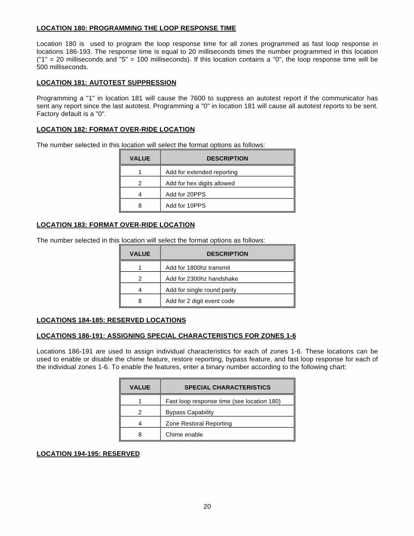
LOCATION 180: PROGRAMMING THE LOOP RESPONSE TIME
Location 180 is used to program the loop response time for all zones programmed as fast loop response inlocations 186-193. The response time is equal to 20 milliseconds times the number programmed in this location("1" = 20 milliseconds and "5" = 100 milliseconds). If this location contains a "0", the loop response time will be500 milliseconds.
LOCATION 181: AUTOTEST SUPPRESSION
Programming a "1" in location 181 will cause the 7600 to suppress an autotest report if the communicator hassent any report since the last autotest. Programming a "0" in location 181 will cause all autotest reports to be sent.Factory default is a "0".
LOCATION 182: FORMAT OVER-RIDE LOCATION
The number selected in this location will select the format options as follows:
VALUE DESCRIPTION
1 Add for extended reporting
2 Add for hex digits allowed
4 Add for 20PPS
8 Add for 10PPS
LOCATION 183: FORMAT OVER-RIDE LOCATION
The number selected in this location will select the format options as follows:
VALUE DESCRIPTION
1 Add for 1800hz transmit
2 Add for 2300hz handshake
4 Add for single round parity
8 Add for 2 digit event code
LOCATIONS 184-185: RESERVED LOCATIONS LOCATIONS 186-191: ASSIGNING SPECIAL CHARACTERISTICS FOR ZONES 1-6
Locations 186-191 are used to assign individual characteristics for each of zones 1-6. These locations can beused to enable or disable the chime feature, restore reporting, bypass feature, and fast loop response for each ofthe individual zones 1-6. To enable the features, enter a binary number according to the following chart:
VALUE SPECIAL CHARACTERISTICS
1 Fast loop response time (see location 180)
2 Bypass Capability
4 Zone Restoral Reporting
8 Chime enable
LOCATION 194-195: RESERVED
21
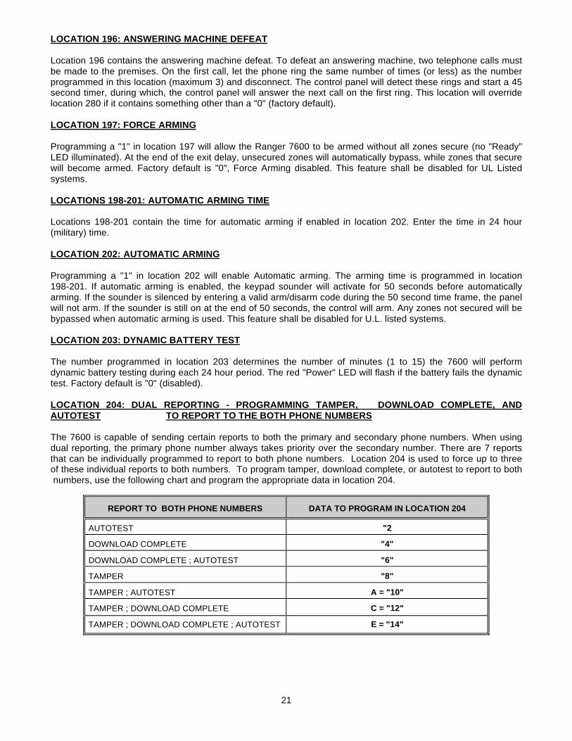
LOCATION 196: ANSWERING MACHINE DEFEAT Location 196 contains the answering machine defeat. To defeat an answering machine, two telephone calls mustbe made to the premises. On the first call, let the phone ring the same number of times (or less) as the numberprogrammed in this location (maximum 3) and disconnect. The control panel will detect these rings and start a 45second timer, during which, the control panel will answer the next call on the first ring. This location will overridelocation 280 if it contains something other than a "0" (factory default).
LOCATION 197: FORCE ARMING Programming a "1" in location 197 will allow the Ranger 7600 to be armed without all zones secure (no "Ready"LED illuminated). At the end of the exit delay, unsecured zones will automatically bypass, while zones that securewill become armed. Factory default is "0", Force Arming disabled. This feature shall be disabled for UL Listedsystems.
LOCATIONS 198-201: AUTOMATIC ARMING TIME
Locations 198-201 contain the time for automatic arming if enabled in location 202. Enter the time in 24 hour(military) time.
LOCATION 202: AUTOMATIC ARMING Programming a "1" in location 202 will enable Automatic arming. The arming time is programmed in location198-201. If automatic arming is enabled, the keypad sounder will activate for 50 seconds before automaticallyarming. If the sounder is silenced by entering a valid arm/disarm code during the 50 second time frame, the panelwill not arm. If the sounder is still on at the end of 50 seconds, the control will arm. Any zones not secured will bebypassed when automatic arming is used. This feature shall be disabled for U.L. listed systems.
LOCATION 203: DYNAMIC BATTERY TEST The number programmed in location 203 determines the number of minutes (1 to 15) the 7600 will performdynamic battery testing during each 24 hour period. The red "Power" LED will flash if the battery fails the dynamictest. Factory default is "0" (disabled). LOCATION 204: DUAL REPORTING - PROGRAMMING TAMPER, DOWNLOAD COMPLETE, ANDAUTOTEST TO REPORT TO THE BOTH PHONE NUMBERS The 7600 is capable of sending certain reports to both the primary and secondary phone numbers. When usingdual reporting, the primary phone number always takes priority over the secondary number. There are 7 reportsthat can be individually programmed to report to both phone numbers. Location 204 is used to force up to threeof these individual reports to both numbers. To program tamper, download complete, or autotest to report to both numbers, use the following chart and program the appropriate data in location 204.
REPORT TO BOTH PHONE NUMBERS DATA TO PROGRAM IN LOCATION 204
AUTOTEST "2
DOWNLOAD COMPLETE "4"
DOWNLOAD COMPLETE ; AUTOTEST "6"
TAMPER "8"
TAMPER ; AUTOTEST A = "10"
TAMPER ; DOWNLOAD COMPLETE C = "12"
TAMPER ; DOWNLOAD COMPLETE ; AUTOTEST E = "14"
22
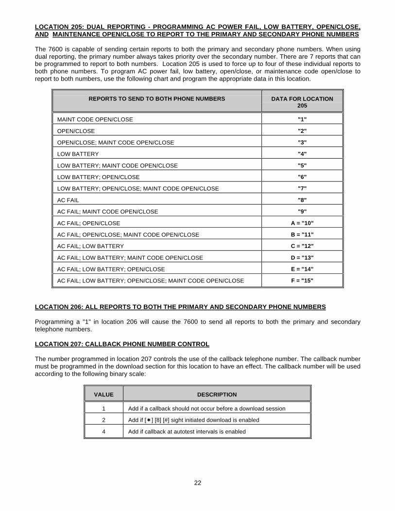
LOCATION 205: DUAL REPORTING - PROGRAMMING AC POWER FAIL, LOW BATTERY, OPEN/CLOSE,AND MAINTENANCE OPEN/CLOSE TO REPORT TO THE PRIMARY AND SECONDARY PHONE NUMBERS The 7600 is capable of sending certain reports to both the primary and secondary phone numbers. When usingdual reporting, the primary number always takes priority over the secondary number. There are 7 reports that canbe programmed to report to both numbers. Location 205 is used to force up to four of these individual reports toboth phone numbers. To program AC power fail, low battery, open/close, or maintenance code open/close toreport to both numbers, use the following chart and program the appropriate data in this location.
REPORTS TO SEND TO BOTH PHONE NUMBERS DATA FOR LOCATION205
MAINT CODE OPEN/CLOSE "1"
OPEN/CLOSE "2"
OPEN/CLOSE; MAINT CODE OPEN/CLOSE "3"
LOW BATTERY "4"
LOW BATTERY; MAINT CODE OPEN/CLOSE "5"
LOW BATTERY; OPEN/CLOSE "6"
LOW BATTERY; OPEN/CLOSE; MAINT CODE OPEN/CLOSE "7"
AC FAIL "8"
AC FAIL; MAINT CODE OPEN/CLOSE "9"
AC FAIL; OPEN/CLOSE A = "10"
AC FAIL; OPEN/CLOSE; MAINT CODE OPEN/CLOSE B = "11"
AC FAIL; LOW BATTERY C = "12"
AC FAIL; LOW BATTERY; MAINT CODE OPEN/CLOSE D = "13"
AC FAIL; LOW BATTERY; OPEN/CLOSE E = "14"
AC FAIL; LOW BATTERY; OPEN/CLOSE; MAINT CODE OPEN/CLOSE F = "15"
LOCATION 206: ALL REPORTS TO BOTH THE PRIMARY AND SECONDARY PHONE NUMBERS
Programming a "1" in location 206 will cause the 7600 to send all reports to both the primary and secondarytelephone numbers. LOCATION 207: CALLBACK PHONE NUMBER CONTROL The number programmed in location 207 controls the use of the callback telephone number. The callback numbermust be programmed in the download section for this location to have an effect. The callback number will be usedaccording to the following binary scale:
VALUE DESCRIPTION
1 Add if a callback should not occur before a download session
2 Add if [¬] [8] [#] sight initiated download is enabled
4 Add if callback at autotest intervals is enabled
23
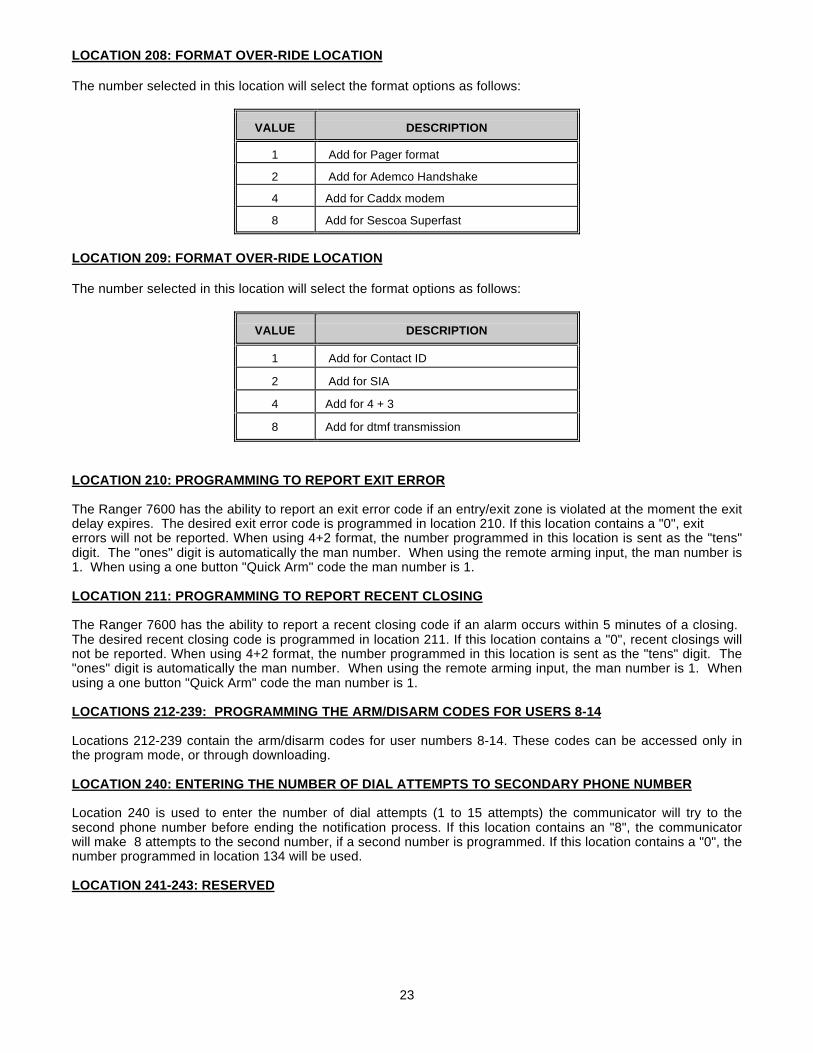
LOCATION 208: FORMAT OVER-RIDE LOCATION The number selected in this location will select the format options as follows:
VALUE DESCRIPTION
1 Add for Pager format
2 Add for Ademco Handshake
4 Add for Caddx modem
8 Add for Sescoa Superfast
LOCATION 209: FORMAT OVER-RIDE LOCATION The number selected in this location will select the format options as follows:
VALUE DESCRIPTION
1 Add for Contact ID
2 Add for SIA
4 Add for 4 + 3
8 Add for dtmf transmission
LOCATION 210: PROGRAMMING TO REPORT EXIT ERROR The Ranger 7600 has the ability to report an exit error code if an entry/exit zone is violated at the moment the exitdelay expires. The desired exit error code is programmed in location 210. If this location contains a "0", exiterrors will not be reported. When using 4+2 format, the number programmed in this location is sent as the "tens"digit. The "ones" digit is automatically the man number. When using the remote arming input, the man number is1. When using a one button "Quick Arm" code the man number is 1. LOCATION 211: PROGRAMMING TO REPORT RECENT CLOSING
The Ranger 7600 has the ability to report a recent closing code if an alarm occurs within 5 minutes of a closing. The desired recent closing code is programmed in location 211. If this location contains a "0", recent closings willnot be reported. When using 4+2 format, the number programmed in this location is sent as the "tens" digit. The"ones" digit is automatically the man number. When using the remote arming input, the man number is 1. Whenusing a one button "Quick Arm" code the man number is 1. LOCATIONS 212-239: PROGRAMMING THE ARM/DISARM CODES FOR USERS 8-14
Locations 212-239 contain the arm/disarm codes for user numbers 8-14. These codes can be accessed only inthe program mode, or through downloading.
LOCATION 240: ENTERING THE NUMBER OF DIAL ATTEMPTS TO SECONDARY PHONE NUMBER
Location 240 is used to enter the number of dial attempts (1 to 15 attempts) the communicator will try to thesecond phone number before ending the notification process. If this location contains an "8", the communicatorwill make 8 attempts to the second number, if a second number is programmed. If this location contains a "0", thenumber programmed in location 134 will be used.
LOCATION 241-243: RESERVED
24
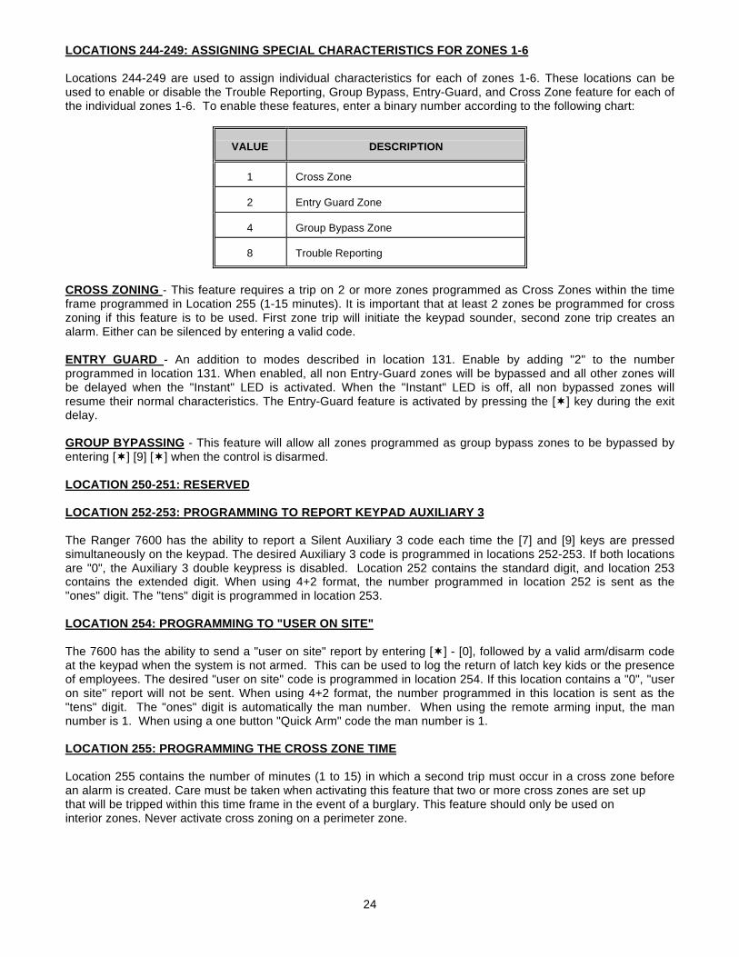
LOCATIONS 244-249: ASSIGNING SPECIAL CHARACTERISTICS FOR ZONES 1-6
Locations 244-249 are used to assign individual characteristics for each of zones 1-6. These locations can beused to enable or disable the Trouble Reporting, Group Bypass, Entry-Guard, and Cross Zone feature for each ofthe individual zones 1-6. To enable these features, enter a binary number according to the following chart:
VALUE DESCRIPTION
1 Cross Zone
2 Entry Guard Zone
4 Group Bypass Zone
8 Trouble Reporting
CROSS ZONING - This feature requires a trip on 2 or more zones programmed as Cross Zones within the timeframe programmed in Location 255 (1-15 minutes). It is important that at least 2 zones be programmed for crosszoning if this feature is to be used. First zone trip will initiate the keypad sounder, second zone trip creates analarm. Either can be silenced by entering a valid code.
ENTRY GUARD - An addition to modes described in location 131. Enable by adding "2" to the numberprogrammed in location 131. When enabled, all non Entry-Guard zones will be bypassed and all other zones willbe delayed when the "Instant" LED is activated. When the "Instant" LED is off, all non bypassed zones willresume their normal characteristics. The Entry-Guard feature is activated by pressing the [¬] key during the exitdelay. GROUP BYPASSING - This feature will allow all zones programmed as group bypass zones to be bypassed byentering [¬] [9] [¬] when the control is disarmed.
LOCATION 250-251: RESERVED
LOCATION 252-253: PROGRAMMING TO REPORT KEYPAD AUXILIARY 3
The Ranger 7600 has the ability to report a Silent Auxiliary 3 code each time the [7] and [9] keys are pressedsimultaneously on the keypad. The desired Auxiliary 3 code is programmed in locations 252-253. If both locationsare "0", the Auxiliary 3 double keypress is disabled. Location 252 contains the standard digit, and location 253contains the extended digit. When using 4+2 format, the number programmed in location 252 is sent as the"ones" digit. The "tens" digit is programmed in location 253. LOCATION 254: PROGRAMMING TO "USER ON SITE"
The 7600 has the ability to send a "user on site" report by entering [¬] - [0], followed by a valid arm/disarm codeat the keypad when the system is not armed. This can be used to log the return of latch key kids or the presenceof employees. The desired "user on site" code is programmed in location 254. If this location contains a "0", "useron site" report will not be sent. When using 4+2 format, the number programmed in this location is sent as the"tens" digit. The "ones" digit is automatically the man number. When using the remote arming input, the mannumber is 1. When using a one button "Quick Arm" code the man number is 1. LOCATION 255: PROGRAMMING THE CROSS ZONE TIME
Location 255 contains the number of minutes (1 to 15) in which a second trip must occur in a cross zone beforean alarm is created. Care must be taken when activating this feature that two or more cross zones are set upthat will be tripped within this time frame in the event of a burglary. This feature should only be used oninterior zones. Never activate cross zoning on a perimeter zone.
25
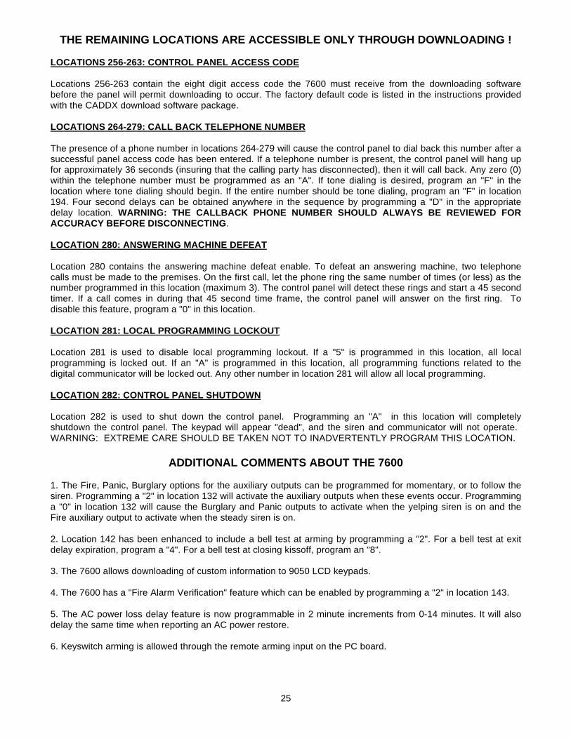
THE REMAINING LOCATIONS ARE ACCESSIBLE ONLY THROUGH DOWNLOADING !
LOCATIONS 256-263: CONTROL PANEL ACCESS CODE
Locations 256-263 contain the eight digit access code the 7600 must receive from the downloading softwarebefore the panel will permit downloading to occur. The factory default code is listed in the instructions providedwith the CADDX download software package. LOCATIONS 264-279: CALL BACK TELEPHONE NUMBER The presence of a phone number in locations 264-279 will cause the control panel to dial back this number after asuccessful panel access code has been entered. If a telephone number is present, the control panel will hang upfor approximately 36 seconds (insuring that the calling party has disconnected), then it will call back. Any zero (0)within the telephone number must be programmed as an "A". If tone dialing is desired, program an "F" in thelocation where tone dialing should begin. If the entire number should be tone dialing, program an "F" in location194. Four second delays can be obtained anywhere in the sequence by programming a "D" in the appropriatedelay location. WARNING: THE CALLBACK PHONE NUMBER SHOULD ALWAYS BE REVIEWED FORACCURACY BEFORE DISCONNECTING.
LOCATION 280: ANSWERING MACHINE DEFEAT Location 280 contains the answering machine defeat enable. To defeat an answering machine, two telephonecalls must be made to the premises. On the first call, let the phone ring the same number of times (or less) as thenumber programmed in this location (maximum 3). The control panel will detect these rings and start a 45 secondtimer. If a call comes in during that 45 second time frame, the control panel will answer on the first ring. Todisable this feature, program a "0" in this location.
LOCATION 281: LOCAL PROGRAMMING LOCKOUT
Location 281 is used to disable local programming lockout. If a "5" is programmed in this location, all localprogramming is locked out. If an "A" is programmed in this location, all programming functions related to thedigital communicator will be locked out. Any other number in location 281 will allow all local programming.
LOCATION 282: CONTROL PANEL SHUTDOWN Location 282 is used to shut down the control panel. Programming an "A" in this location will completelyshutdown the control panel. The keypad will appear "dead", and the siren and communicator will not operate. WARNING: EXTREME CARE SHOULD BE TAKEN NOT TO INADVERTENTLY PROGRAM THIS LOCATION.
ADDITIONAL COMMENTS ABOUT THE 7600
1. The Fire, Panic, Burglary options for the auxiliary outputs can be programmed for momentary, or to follow thesiren. Programming a "2" in location 132 will activate the auxiliary outputs when these events occur. Programminga "0" in location 132 will cause the Burglary and Panic outputs to activate when the yelping siren is on and theFire auxiliary output to activate when the steady siren is on.
2. Location 142 has been enhanced to include a bell test at arming by programming a "2". For a bell test at exitdelay expiration, program a "4". For a bell test at closing kissoff, program an "8".
3. The 7600 allows downloading of custom information to 9050 LCD keypads.
4. The 7600 has a "Fire Alarm Verification" feature which can be enabled by programming a "2" in location 143.
5. The AC power loss delay feature is now programmable in 2 minute increments from 0-14 minutes. It will alsodelay the same time when reporting an AC power restore.
6. Keyswitch arming is allowed through the remote arming input on the PC board.
26
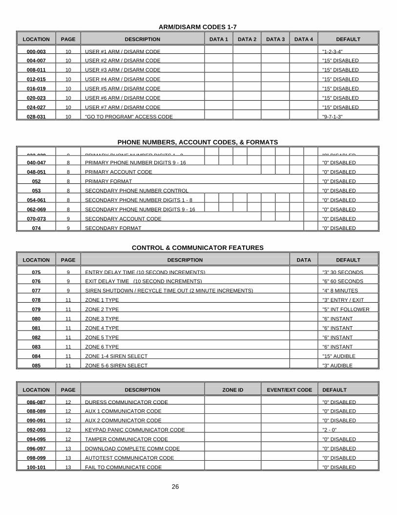
ARM/DISARM CODES 1-7
LOCATION PAGE DESCRIPTION DATA 1 DATA 2 DATA 3 DATA 4 DEFAULT
000-003 10 USER #1 ARM / DISARM CODE "1-2-3-4"
004-007 10 USER #2 ARM / DISARM CODE "15" DISABLED
008-011 10 USER #3 ARM / DISARM CODE "15" DISABLED
012-015 10 USER #4 ARM / DISARM CODE "15" DISABLED
016-019 10 USER #5 ARM / DISARM CODE "15" DISABLED
020-023 10 USER #6 ARM / DISARM CODE "15" DISABLED
024-027 10 USER #7 ARM / DISARM CODE "15" DISABLED
028-031 10 "GO TO PROGRAM" ACCESS CODE "9-7-1-3"
PHONE NUMBERS, ACCOUNT CODES, & FORMATS
032-039 8 PRIMARY PHONE NUMBER DIGITS 1 - 8 "0" DISABLED040-047 8 PRIMARY PHONE NUMBER DIGITS 9 - 16 "0" DISABLED
048-051 8 PRIMARY ACCOUNT CODE "0" DISABLED
052 8 PRIMARY FORMAT "0" DISABLED
053 8 SECONDARY PHONE NUMBER CONTROL "0" DISABLED
054-061 8 SECONDARY PHONE NUMBER DIGITS 1 - 8 "0" DISABLED
062-069 8 SECONDARY PHONE NUMBER DIGITS 9 - 16 "0" DISABLED
070-073 9 SECONDARY ACCOUNT CODE "0" DISABLED
074 9 SECONDARY FORMAT "0" DISABLED
CONTROL & COMMUNICATOR FEATURES
LOCATION PAGE DESCRIPTION DATA DEFAULT
075 9 ENTRY DELAY TIME (10 SECOND INCREMENTS) "3" 30 SECONDS
076 9 EXIT DELAY TIME (10 SECOND INCREMENTS) "6" 60 SECONDS
077 9 SIREN SHUTDOWN / RECYCLE TIME OUT (2 MINUTE INCREMENTS) "4" 8 MINUTES
078 11 ZONE 1 TYPE "3" ENTRY / EXIT
079 11 ZONE 2 TYPE "5" INT FOLLOWER
080 11 ZONE 3 TYPE "6" INSTANT
081 11 ZONE 4 TYPE "6" INSTANT
082 11 ZONE 5 TYPE "6" INSTANT
083 11 ZONE 6 TYPE "6" INSTANT
084 11 ZONE 1-4 SIREN SELECT "15" AUDIBLE
085 11 ZONE 5-6 SIREN SELECT "3" AUDIBLE
LOCATION PAGE DESCRIPTION ZONE ID EVENT/EXT CODE DEFAULT
086-087 12 DURESS COMMUNICATOR CODE "0" DISABLED
088-089 12 AUX 1 COMMUNICATOR CODE "0" DISABLED
090-091 12 AUX 2 COMMUNICATOR CODE "0" DISABLED
092-093 12 KEYPAD PANIC COMMUNICATOR CODE "2 - 0"
094-095 12 TAMPER COMMUNICATOR CODE "0" DISABLED
096-097 13 DOWNLOAD COMPLETE COMM CODE "0" DISABLED
098-099 13 AUTOTEST COMMUNICATOR CODE "0" DISABLED
100-101 13 FAIL TO COMMUNICATE CODE "0" DISABLED
27
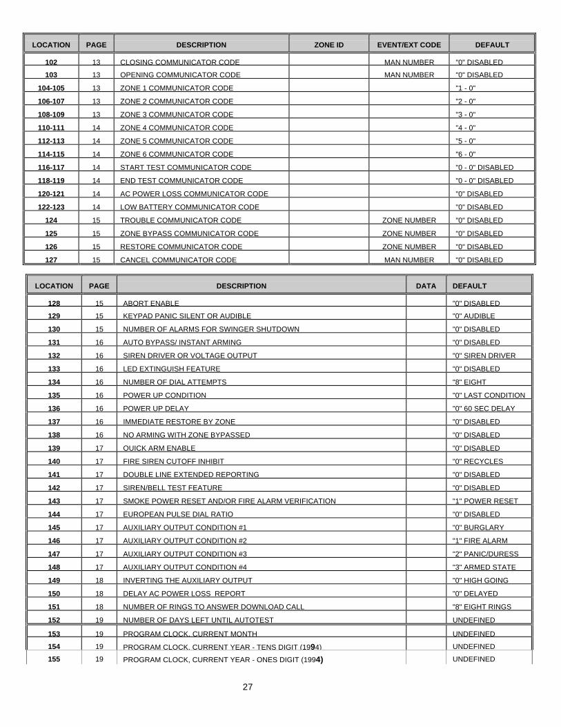
LOCATION PAGE DESCRIPTION ZONE ID EVENT/EXT CODE DEFAULT
102 13 CLOSING COMMUNICATOR CODE MAN NUMBER "0" DISABLED
103 13 OPENING COMMUNICATOR CODE MAN NUMBER "0" DISABLED
104-105 13 ZONE 1 COMMUNICATOR CODE "1 - 0"
106-107 13 ZONE 2 COMMUNICATOR CODE "2 - 0"
108-109 13 ZONE 3 COMMUNICATOR CODE "3 - 0"
110-111 14 ZONE 4 COMMUNICATOR CODE "4 - 0"
112-113 14 ZONE 5 COMMUNICATOR CODE "5 - 0"
114-115 14 ZONE 6 COMMUNICATOR CODE "6 - 0"
116-117 14 START TEST COMMUNICATOR CODE "0 - 0" DISABLED
118-119 14 END TEST COMMUNICATOR CODE "0 - 0" DISABLED
120-121 14 AC POWER LOSS COMMUNICATOR CODE "0" DISABLED
122-123 14 LOW BATTERY COMMUNICATOR CODE "0" DISABLED
124 15 TROUBLE COMMUNICATOR CODE ZONE NUMBER "0" DISABLED
125 15 ZONE BYPASS COMMUNICATOR CODE ZONE NUMBER "0" DISABLED
126 15 RESTORE COMMUNICATOR CODE ZONE NUMBER "0" DISABLED
127 15 CANCEL COMMUNICATOR CODE MAN NUMBER "0" DISABLED
LOCATION PAGE DESCRIPTION DATA DEFAULT
128 15 ABORT ENABLE "0" DISABLED
129 15 KEYPAD PANIC SILENT OR AUDIBLE "0" AUDIBLE
130 15 NUMBER OF ALARMS FOR SWINGER SHUTDOWN "0" DISABLED
131 16 AUTO BYPASS/ INSTANT ARMING "0" DISABLED
132 16 SIREN DRIVER OR VOLTAGE OUTPUT "0" SIREN DRIVER
133 16 LED EXTINGUISH FEATURE "0" DISABLED
134 16 NUMBER OF DIAL ATTEMPTS "8" EIGHT
135 16 POWER UP CONDITION "0" LAST CONDITION
136 16 POWER UP DELAY "0" 60 SEC DELAY
137 16 IMMEDIATE RESTORE BY ZONE "0" DISABLED
138 16 NO ARMING WITH ZONE BYPASSED "0" DISABLED
139 17 QUICK ARM ENABLE "0" DISABLED
140 17 FIRE SIREN CUTOFF INHIBIT "0" RECYCLES
141 17 DOUBLE LINE EXTENDED REPORTING "0" DISABLED
142 17 SIREN/BELL TEST FEATURE "0" DISABLED
143 17 SMOKE POWER RESET AND/OR FIRE ALARM VERIFICATION "1" POWER RESET
144 17 EUROPEAN PULSE DIAL RATIO "0" DISABLED
145 17 AUXILIARY OUTPUT CONDITION #1 "0" BURGLARY
146 17 AUXILIARY OUTPUT CONDITION #2 "1" FIRE ALARM
147 17 AUXILIARY OUTPUT CONDITION #3 "2" PANIC/DURESS
148 17 AUXILIARY OUTPUT CONDITION #4 "3" ARMED STATE
149 18 INVERTING THE AUXILIARY OUTPUT "0" HIGH GOING
150 18 DELAY AC POWER LOSS REPORT "0" DELAYED
151 18 NUMBER OF RINGS TO ANSWER DOWNLOAD CALL "8" EIGHT RINGS
152 19 NUMBER OF DAYS LEFT UNTIL AUTOTEST UNDEFINED
153 19 PROGRAM CLOCK, CURRENT MONTH UNDEFINED
154 19 PROGRAM CLOCK, CURRENT YEAR - TENS DIGIT (1994) UNDEFINED
155 19 PROGRAM CLOCK, CURRENT YEAR - ONES DIGIT (1994) UNDEFINED
28
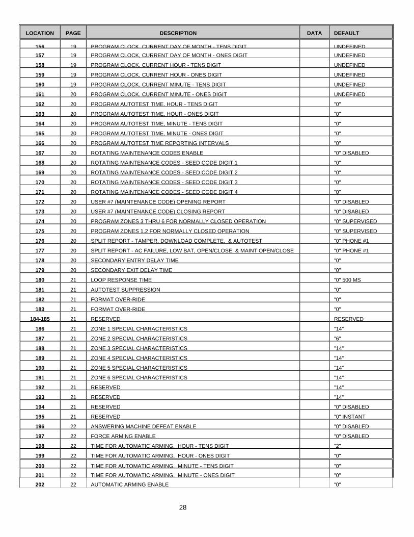
LOCATION PAGE DESCRIPTION DATA DEFAULT
156 19 PROGRAM CLOCK, CURRENT DAY OF MONTH - TENS DIGIT UNDEFINED
157 19 PROGRAM CLOCK, CURRENT DAY OF MONTH - ONES DIGIT UNDEFINED
158 19 PROGRAM CLOCK, CURRENT HOUR - TENS DIGIT UNDEFINED
159 19 PROGRAM CLOCK, CURRENT HOUR - ONES DIGIT UNDEFINED
160 19 PROGRAM CLOCK, CURRENT MINUTE - TENS DIGIT UNDEFINED
161 20 PROGRAM CLOCK, CURRENT MINUTE - ONES DIGIT UNDEFINED
162 20 PROGRAM AUTOTEST TIME, HOUR - TENS DIGIT "0"
163 20 PROGRAM AUTOTEST TIME, HOUR - ONES DIGIT "0"
164 20 PROGRAM AUTOTEST TIME, MINUTE - TENS DIGIT "0"
165 20 PROGRAM AUTOTEST TIME, MINUTE - ONES DIGIT "0"
166 20 PROGRAM AUTOTEST TIME REPORTING INTERVALS "0"
167 20 ROTATING MAINTENANCE CODES ENABLE "0" DISABLED
168 20 ROTATING MAINTENANCE CODES - SEED CODE DIGIT 1 "0"
169 20 ROTATING MAINTENANCE CODES - SEED CODE DIGIT 2 "0"
170 20 ROTATING MAINTENANCE CODES - SEED CODE DIGIT 3 "0"
171 20 ROTATING MAINTENANCE CODES - SEED CODE DIGIT 4 "0"
172 20 USER #7 (MAINTENANCE CODE) OPENING REPORT "0" DISABLED
173 20 USER #7 (MAINTENANCE CODE) CLOSING REPORT "0" DISABLED
174 20 PROGRAM ZONES 3 THRU 6 FOR NORMALLY CLOSED OPERATION "0" SUPERVISED
175 20 PROGRAM ZONES 1,2 FOR NORMALLY CLOSED OPERATION "0" SUPERVISED
176 20 SPLIT REPORT - TAMPER, DOWNLOAD COMPLETE, & AUTOTEST "0" PHONE #1
177 20 SPLIT REPORT - AC FAILURE, LOW BAT, OPEN/CLOSE, & MAINT OPEN/CLOSE "0" PHONE #1
178 20 SECONDARY ENTRY DELAY TIME "0"
179 20 SECONDARY EXIT DELAY TIME "0"
180 21 LOOP RESPONSE TIME "0" 500 MS
181 21 AUTOTEST SUPPRESSION "0"
182 21 FORMAT OVER-RIDE "0"
183 21 FORMAT OVER-RIDE "0"
184-185 21 RESERVED RESERVED
186 21 ZONE 1 SPECIAL CHARACTERISTICS "14"
187 21 ZONE 2 SPECIAL CHARACTERISTICS "6"
188 21 ZONE 3 SPECIAL CHARACTERISTICS "14"
189 21 ZONE 4 SPECIAL CHARACTERISTICS "14"
190 21 ZONE 5 SPECIAL CHARACTERISTICS "14"
191 21 ZONE 6 SPECIAL CHARACTERISTICS "14"
192 21 RESERVED "14"
193 21 RESERVED "14"
194 21 RESERVED "0" DISABLED
195 21 RESERVED "0" INSTANT
196 22 ANSWERING MACHINE DEFEAT ENABLE "0" DISABLED
197 22 FORCE ARMING ENABLE "0" DISABLED
198 22 TIME FOR AUTOMATIC ARMING, HOUR - TENS DIGIT "2"
199 22 TIME FOR AUTOMATIC ARMING, HOUR - ONES DIGIT "0"
200 22 TIME FOR AUTOMATIC ARMING, MINUTE - TENS DIGIT "0"
201 22 TIME FOR AUTOMATIC ARMING, MINUTE - ONES DIGIT "0"
202 22 AUTOMATIC ARMING ENABLE "0"
29
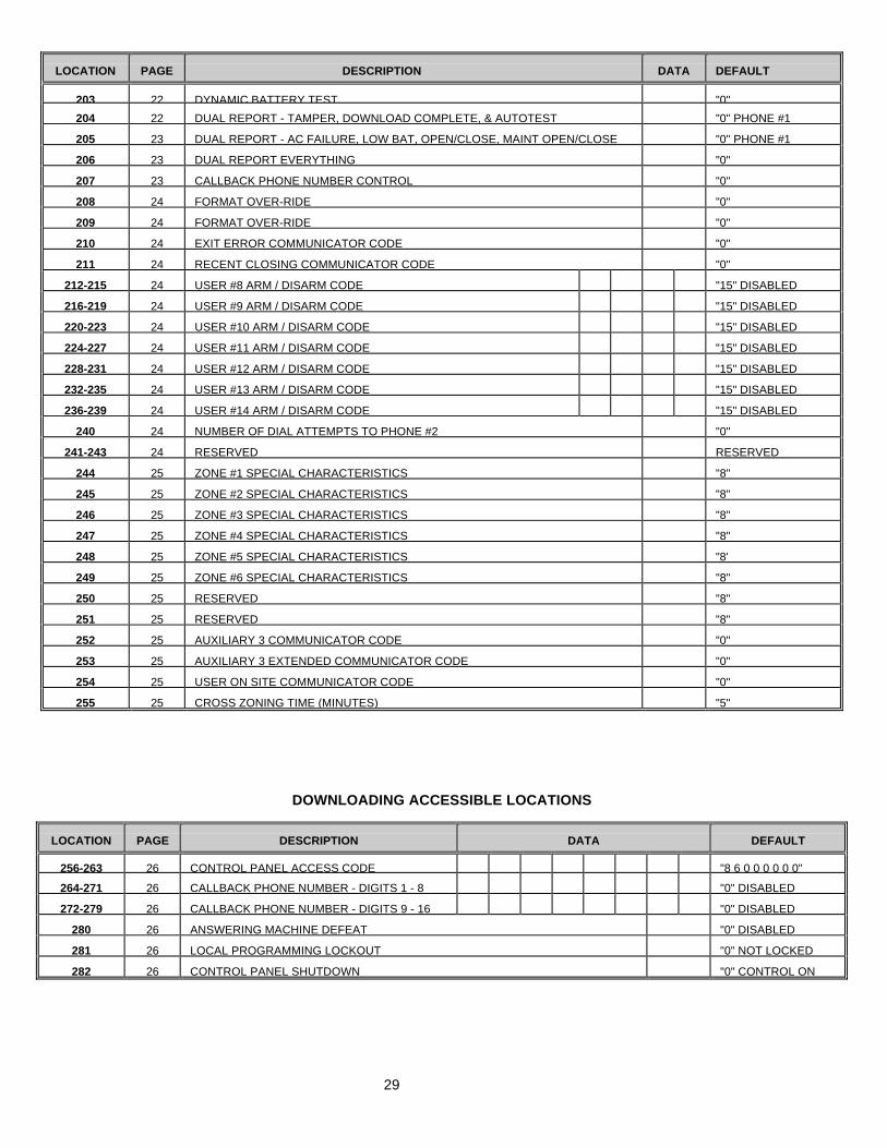
LOCATION PAGE DESCRIPTION DATA DEFAULT
203 22 DYNAMIC BATTERY TEST "0"
204 22 DUAL REPORT - TAMPER, DOWNLOAD COMPLETE, & AUTOTEST "0" PHONE #1
205 23 DUAL REPORT - AC FAILURE, LOW BAT, OPEN/CLOSE, MAINT OPEN/CLOSE "0" PHONE #1
206 23 DUAL REPORT EVERYTHING "0"
207 23 CALLBACK PHONE NUMBER CONTROL "0"
208 24 FORMAT OVER-RIDE "0"
209 24 FORMAT OVER-RIDE "0"
210 24 EXIT ERROR COMMUNICATOR CODE "0"
211 24 RECENT CLOSING COMMUNICATOR CODE "0"
212-215 24 USER #8 ARM / DISARM CODE "15" DISABLED
216-219 24 USER #9 ARM / DISARM CODE "15" DISABLED
220-223 24 USER #10 ARM / DISARM CODE "15" DISABLED
224-227 24 USER #11 ARM / DISARM CODE "15" DISABLED
228-231 24 USER #12 ARM / DISARM CODE "15" DISABLED
232-235 24 USER #13 ARM / DISARM CODE "15" DISABLED
236-239 24 USER #14 ARM / DISARM CODE "15" DISABLED
240 24 NUMBER OF DIAL ATTEMPTS TO PHONE #2 "0"
241-243 24 RESERVED RESERVED
244 25 ZONE #1 SPECIAL CHARACTERISTICS "8"
245 25 ZONE #2 SPECIAL CHARACTERISTICS "8"
246 25 ZONE #3 SPECIAL CHARACTERISTICS "8"
247 25 ZONE #4 SPECIAL CHARACTERISTICS "8"
248 25 ZONE #5 SPECIAL CHARACTERISTICS "8'
249 25 ZONE #6 SPECIAL CHARACTERISTICS "8"
250 25 RESERVED "8"
251 25 RESERVED "8"
252 25 AUXILIARY 3 COMMUNICATOR CODE "0"
253 25 AUXILIARY 3 EXTENDED COMMUNICATOR CODE "0"
254 25 USER ON SITE COMMUNICATOR CODE "0"
255 25 CROSS ZONING TIME (MINUTES) "5"
DOWNLOADING ACCESSIBLE LOCATIONS
LOCATION PAGE DESCRIPTION DATA DEFAULT
256-263 26 CONTROL PANEL ACCESS CODE "8 6 0 0 0 0 0 0"
264-271 26 CALLBACK PHONE NUMBER - DIGITS 1 - 8 "0" DISABLED
272-279 26 CALLBACK PHONE NUMBER - DIGITS 9 - 16 "0" DISABLED
280 26 ANSWERING MACHINE DEFEAT "0" DISABLED
281 26 LOCAL PROGRAMMING LOCKOUT "0" NOT LOCKED
282 26 CONTROL PANEL SHUTDOWN "0" CONTROL ON
30
LOCAL TELEPHONE COMPANY INTERFACE INFORMATION
TELEPHONE CONNECTION REQUIREMENTS
Except for telephone company provided ringers, all connections to the telephone network shall be made throughstandard plugs and standard telephone company provided jacks or equivalent in such a manner as to allow forimmediate disconnection of the terminal equipment. Standard jacks shall be so arranged that if the plugconnected thereto is withdrawn, no interference to the operation of the equipment at the customers premiseswhich remains connected to the telephone network, shall occur by reason of such withdrawal. INCIDENCE OF HARM
Should terminal equipment or protective circuitry cause harm to the telephone network, the telephone companyshall, where practical, notify the customer that temporary discontinuance of service may be required; however,where prior notice is not practical, the telephone company may temporarily discontinue service if such action isdeemed reasonable in the circumstances. In the case of such temporary discontinuance, the telephone companyshall promptly notify the customer who will be given the opportunity to correct the situation. The customer alsohas the right to bring a complaint to the FCC if he feels the disconnection is not warranted.
CHANGES IN TELEPHONE COMPANY EQUIPMENT OR FACILITIES The telephone company may make changes in its communications facilities, equipment, operations, orprocedures where such action is reasonably required and proper in its business. Should any such change renderthe customers terminal equipment incompatible with the telephone company facilities, the customer shall be givenadequate notice to make modifications to maintain uninterrupted service.
GENERAL
The FCC prohibits customer provided terminal equipment be connected to party lines.
IMPORTANCE OF THE RINGER EQUIVALENCE NUMBER
The Ringer Equivalence Number of this device is 0.0 B. This number is a representation of the electrical load thatit applies to your telephone line.
MALFUNCTION OF THE EQUIPMENT
In the event that the device should fail to operate properly, the customer shall disconnect the equipment from thetelephone line to determine if it is the customers equipment that is not functioning properly. If the problem is withthe device the customer shall discontinue use until it is repaired.
EQUIPMENT INFORMATION MANUFACTURER OF CONNECTING EQUIPMENT: CADDX-CADDI CONTROLS INC., FCC REGISTRATIONNUMBER: GCQ4DC-17266-AL-E, RINGER EQUIVALENCE: 0.0 B
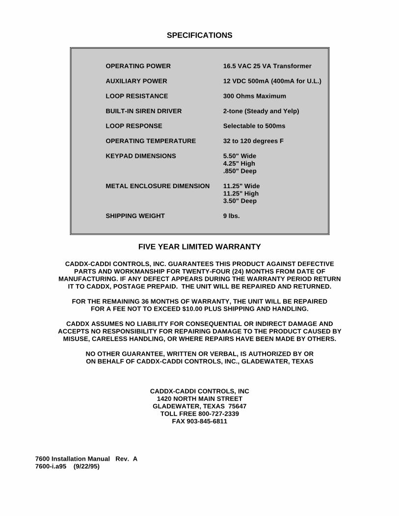
SPECIFICATIONS
OPERATING POWER 16.5 VAC 25 VA Transformer
AUXILIARY POWER 12 VDC 500mA (400mA for U.L.)
LOOP RESISTANCE 300 Ohms Maximum
BUILT-IN SIREN DRIVER 2-tone (Steady and Yelp)
LOOP RESPONSE Selectable to 500ms
OPERATING TEMPERATURE 32 to 120 degrees F
KEYPAD DIMENSIONS 5.50" Wide4.25" High.850" Deep
METAL ENCLOSURE DIMENSION 11.25" Wide11.25" High3.50" Deep
SHIPPING WEIGHT 9 lbs.
FIVE YEAR LIMITED WARRANTY
CADDX-CADDI CONTROLS, INC. GUARANTEES THIS PRODUCT AGAINST DEFECTIVEPARTS AND WORKMANSHIP FOR TWENTY-FOUR (24) MONTHS FROM DATE OF
MANUFACTURING. IF ANY DEFECT APPEARS DURING THE WARRANTY PERIOD RETURNIT TO CADDX, POSTAGE PREPAID. THE UNIT WILL BE REPAIRED AND RETURNED.
FOR THE REMAINING 36 MONTHS OF WARRANTY, THE UNIT WILL BE REPAIREDFOR A FEE NOT TO EXCEED $10.00 PLUS SHIPPING AND HANDLING.
CADDX ASSUMES NO LIABILITY FOR CONSEQUENTIAL OR INDIRECT DAMAGE ANDACCEPTS NO RESPONSIBILITY FOR REPAIRING DAMAGE TO THE PRODUCT CAUSED BY
MISUSE, CARELESS HANDLING, OR WHERE REPAIRS HAVE BEEN MADE BY OTHERS.
NO OTHER GUARANTEE, WRITTEN OR VERBAL, IS AUTHORIZED BY ORON BEHALF OF CADDX-CADDI CONTROLS, INC., GLADEWATER, TEXAS
CADDX-CADDI CONTROLS, INC1420 NORTH MAIN STREET
GLADEWATER, TEXAS 75647TOLL FREE 800-727-2339
FAX 903-845-6811
7600 Installation Manual Rev. A7600-i.a95 (9/22/95)