ieee 802.11e enhanced qos
TRANSCRIPT

Outlines Introduction Traffic Differentiation Hybrid Coordination Function (HCF)
Contention-Based Channel Access – EDCA Controlled Channel Access – HCCA
Block Acknowledgement Direct Link Protocol (DLP)
3
Characteristics of IEEE 802.11e The major enhancement of 802.11e
Traffic differentiation Concept of Transmission Opportunity (TXOP) Enhanced DCF (contention-based) HCP controlled channel access (contention free) Burst ACK (optional) Direct link protocol (DLP)

4
MAC Architecture
• DCF : A contention-base access for 802.11. • PCF : An option to support contention-free access in 802.11.• Hybrid Coordination Function (HCF): IEEE 802.11 Task Group E (TGe)
proposes HCF to provide QoS for real-time applications.
IEEE 802.11 MAC Architecture IEEE 802.11e MAC Architecture
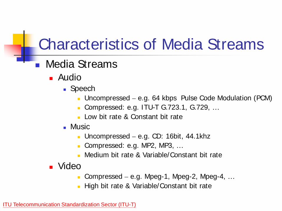
Characteristics of Media Streams Media Streams
Audio Speech
Uncompressed – e.g. 64 kbps Pulse Code Modulation (PCM) Compressed: e.g. ITU-T G.723.1, G.729, … Low bit rate & Constant bit rate
Music Uncompressed – e.g. CD: 16bit, 44.1khz Compressed: e.g. MP2, MP3, … Medium bit rate & Variable/Constant bit rate
Video Compressed – e.g. Mpeg-1, Mpeg-2, Mpeg-4, … High bit rate & Variable/Constant bit rate
ITU Telecommunication Standardization Sector (ITU-T)
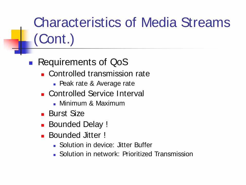
Characteristics of Media Streams (Cont.) Requirements of QoS
Controlled transmission rate Peak rate & Average rate
Controlled Service Interval Minimum & Maximum
Burst Size Bounded Delay ! Bounded Jitter !
Solution in device: Jitter Buffer Solution in network: Prioritized Transmission

Is 802.11 enough for QoS?
DCF can not provide QoS trivially PCF is not enough
Only 1 frame can be sent at each polling Point Coordinator (PC) does not know the QoS
requirement of traffic Can not guarantee the delay and jitter bound

PCF
NAV
SIFS
SIFS
Busy CF-D1
CF-U1
CF-D2
SIFS
CF-U2
CF-D3
SIFS
SIFS SIFS
CF-D4
CF-U4
CF-End
PIFS
SIFS
CFP
Super Frame
CP
Reset NAV
CF_Max_Duration
Dx = Down TrafficUx = Up Traffic
B
PIFS
D1+Poll
U1+Ack
D2+Ack+Poll
U2+Ack
Ack+Poll
D4+Poll
U4+Ack
CF-End+Ack
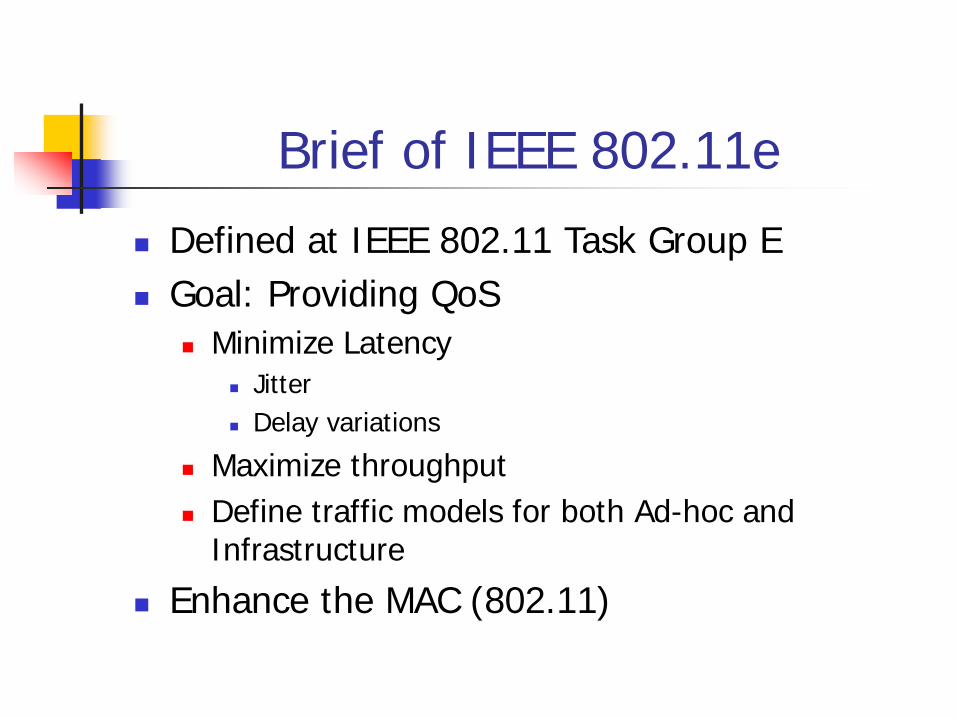
Brief of IEEE 802.11e Defined at IEEE 802.11 Task Group E Goal: Providing QoS
Minimize Latency Jitter Delay variations
Maximize throughput Define traffic models for both Ad-hoc and
Infrastructure Enhance the MAC (802.11)
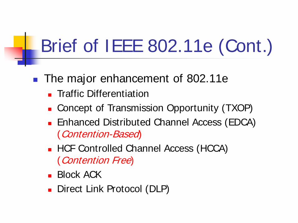
Brief of IEEE 802.11e (Cont.) The major enhancement of 802.11e
Traffic Differentiation Concept of Transmission Opportunity (TXOP) Enhanced Distributed Channel Access (EDCA)
(Contention-Based) HCF Controlled Channel Access (HCCA)
(Contention Free) Block ACK Direct Link Protocol (DLP)
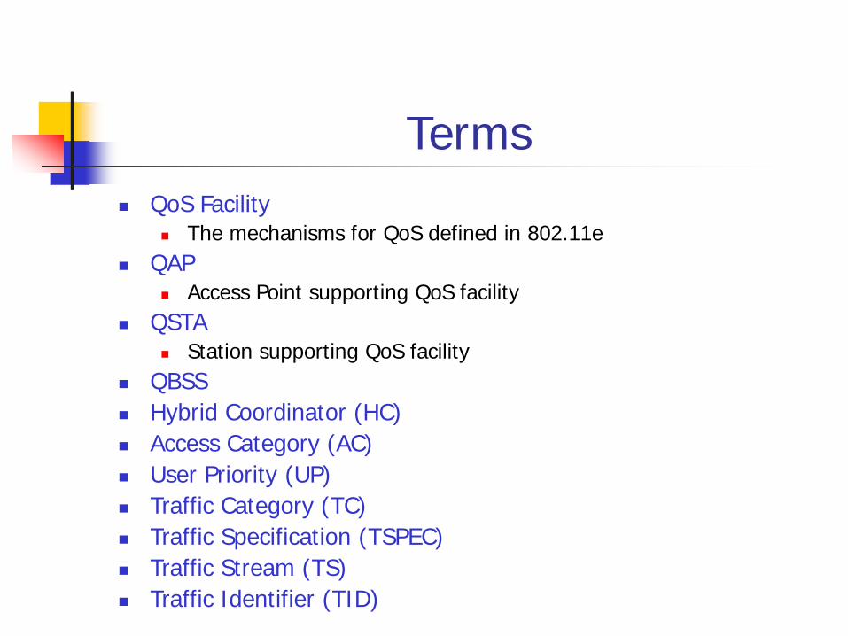
Terms QoS Facility
The mechanisms for QoS defined in 802.11e QAP
Access Point supporting QoS facility QSTA
Station supporting QoS facility QBSS Hybrid Coordinator (HC) Access Category (AC) User Priority (UP) Traffic Category (TC) Traffic Specification (TSPEC) Traffic Stream (TS) Traffic Identifier (TID)

Traffic Differentiation
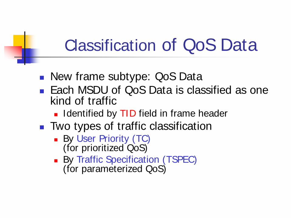
Classification of QoS Data New frame subtype: QoS Data Each MSDU of QoS Data is classified as one
kind of traffic Identified by TID field in frame header
Two types of traffic classification By User Priority (TC)
(for prioritized QoS) By Traffic Specification (TSPEC)
(for parameterized QoS)
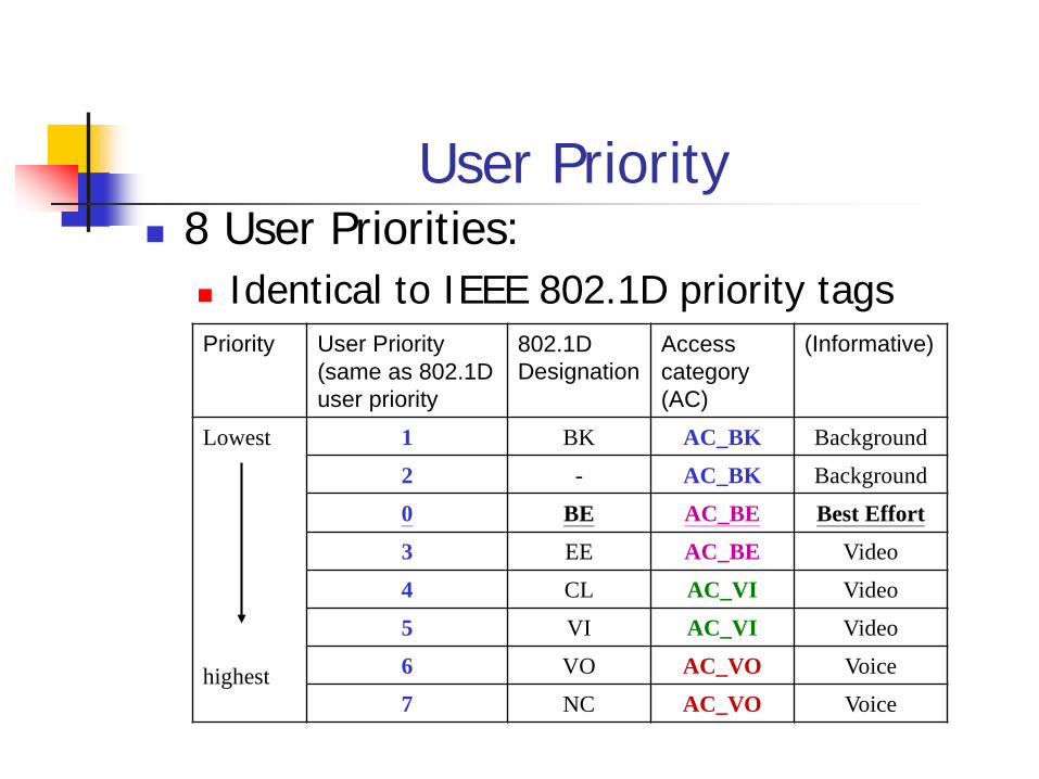
User Priority 8 User Priorities:
Identical to IEEE 802.1D priority tagsPriority User Priority
(same as 802.1D user priority
802.1D Designation
Access category (AC)
(Informative)
Lowest
highest
1 BK AC_BK Background2 - AC_BK Background0 BE AC_BE Best Effort3 EE AC_BE Video4 CL AC_VI Video5 VI AC_VI Video6 VO AC_VO Voice7 NC AC_VO Voice
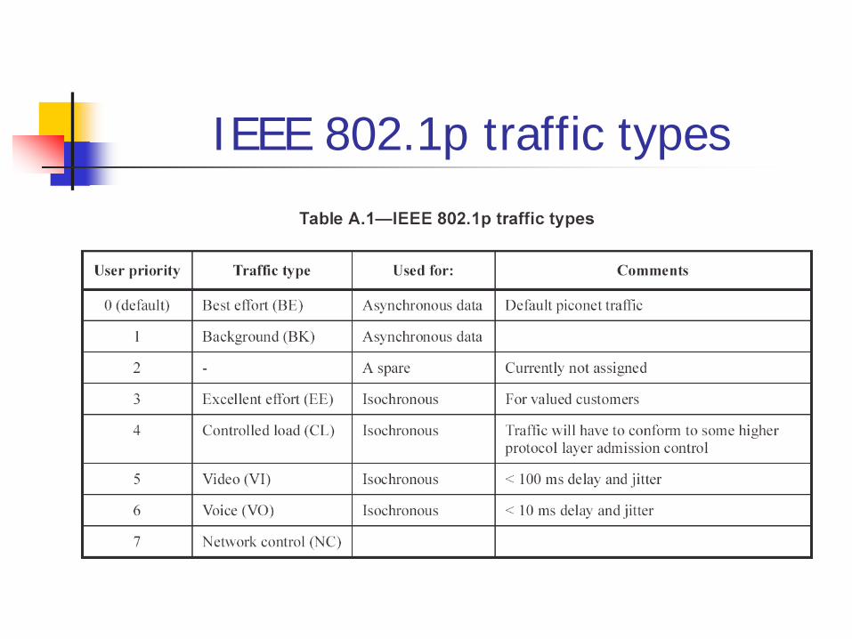
IEEE 802.1p traffic types
User Priority (cont.)
Priority Determination of MSDU Directly: provided at MAC SAP Indirectly: defined in TSPEC’s
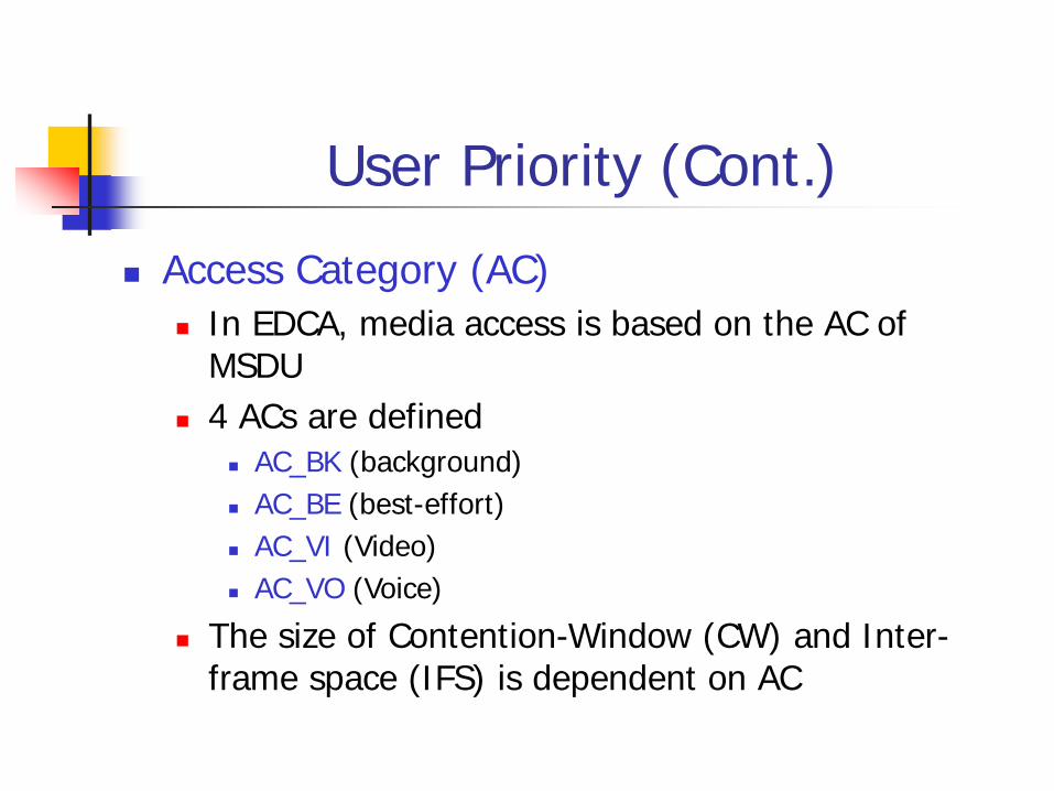
User Priority (Cont.) Access Category (AC)
In EDCA, media access is based on the AC of MSDU
4 ACs are defined AC_BK (background) AC_BE (best-effort) AC_VI (Video) AC_VO (Voice)
The size of Contention-Window (CW) and Inter-frame space (IFS) is dependent on AC

Traffic Specification Traffic Specification (TSPEC)
Characteristics of traffic streams created by negotiation between QSTA and Hybrid Coordinator (HC)
Hybrid Coordinator can schedule the polling within CFP and the data transmission of the traffic stream accordingly
TSPEC Setup & Delete Use Management Frame with new subtype
Action containing TSPEC Element

Frame FormatsMAC frame format:
QoS Control Field:
Traffic Identifier (TID)
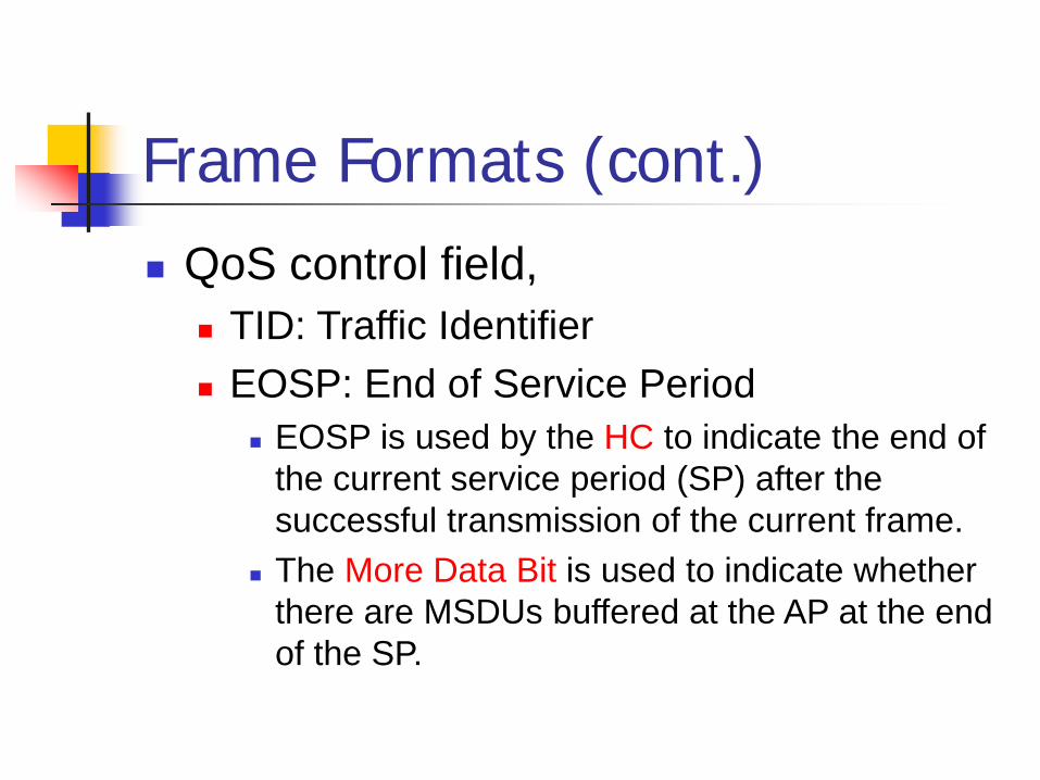
Frame Formats (cont.) QoS control field,
TID: Traffic Identifier EOSP: End of Service Period
EOSP is used by the HC to indicate the end of the current service period (SP) after the successful transmission of the current frame.
The More Data Bit is used to indicate whether there are MSDUs buffered at the AP at the end of the SP.
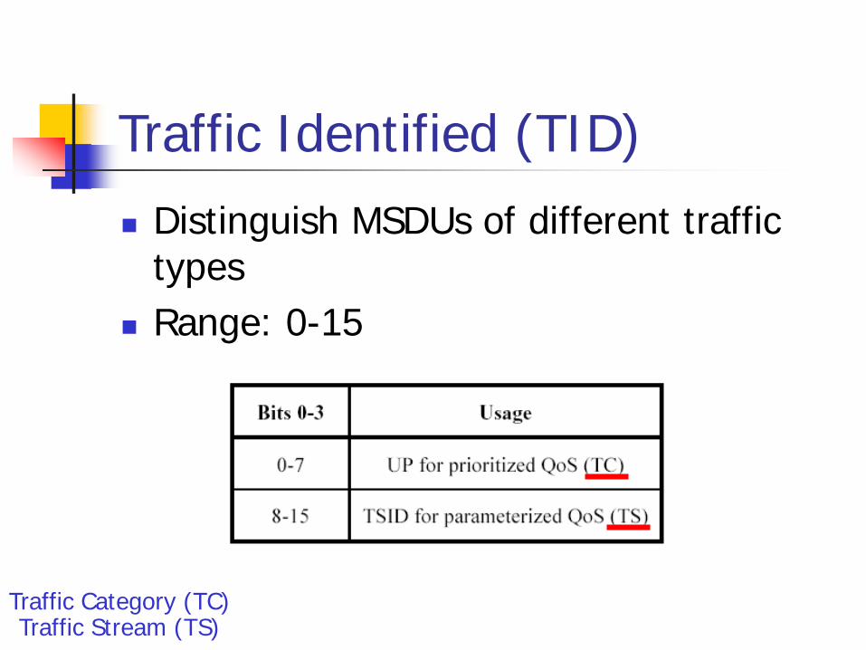
Traffic Identified (TID) Distinguish MSDUs of different traffic
types Range: 0-15
Traffic Category (TC)Traffic Stream (TS)
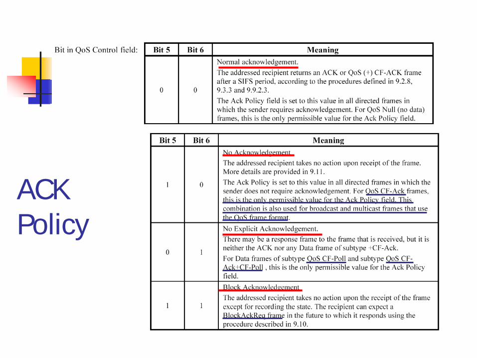
ACKPolicy

Ack Policy Normal ACK: An ACK or QoS CF-ACK is required after
a SIFS. No ACK: No required ACK response No Explicit ACK: There may be a response frame, but
it is neither the ACK nor any Data frame of subtype +CF-ACK. (e.g., QoS CF-Poll, or QoS CF-ACK+CF-Poll).
Block ACK: Instead of transmitting an individual ACK for every MPDU (i.e., frame), multiple MPDUs can be acknowledged together using a single Block ACK frame

Frame Control Field

25
HCF Controlled Access - New Data/Management/Control Frames
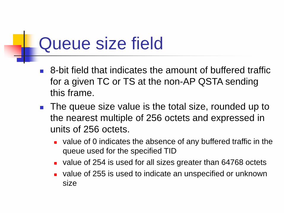
Queue size field 8-bit field that indicates the amount of buffered traffic
for a given TC or TS at the non-AP QSTA sending this frame.
The queue size value is the total size, rounded up to the nearest multiple of 256 octets and expressed in units of 256 octets. value of 0 indicates the absence of any buffered traffic in the
queue used for the specified TID value of 254 is used for all sizes greater than 64768 octets value of 255 is used to indicate an unspecified or unknown
size

27
TXOP A TXOP is defined by a starting time and a
maximum duration. Two types of TXOP: EDCF TXOP and Polled
TXOP. An EDCF TXOP begins when the wireless medium
is determined to be available under the EDCF rules, and the length of TXOP is specified in beacon frames.
An Polled TXOP begins when a QSTA receives a QoS(+)CF-Poll from HC, and the length of TXOP is specified in the QoS(+)CF-Poll.
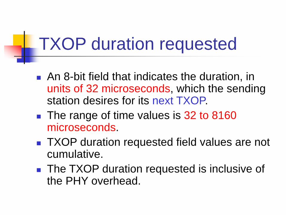
TXOP duration requested
An 8-bit field that indicates the duration, in units of 32 microseconds, which the sending station desires for its next TXOP.
The range of time values is 32 to 8160microseconds.
TXOP duration requested field values are not cumulative.
The TXOP duration requested is inclusive of the PHY overhead.
Duration/ID field Within all data type frames containing
QoS CF-Poll, the Duration/ID value is set to SIFS + TXOP Duration Limit
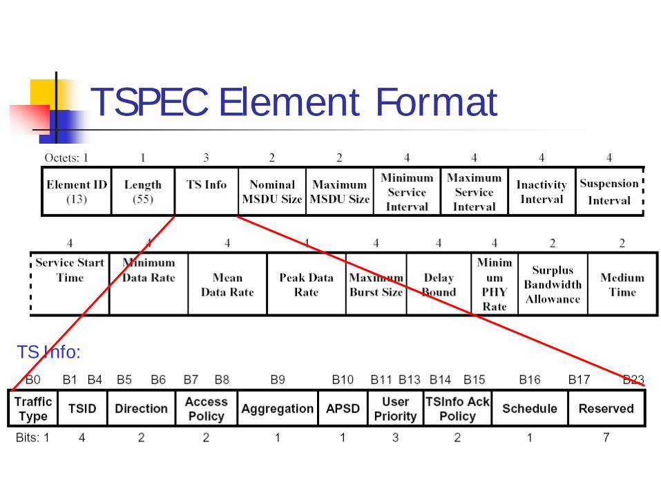
TSPEC Element Format
TS Info:

Traffic Classification (TCLAS) Element For identifying the Traffic Stream (TS)
to which the incoming MSDUs belong

Traffic Classification (TCLAS) Element
Type 0
Type 1 (IPv4)
Type 1 (IPv6)
Type 2

Hybrid Coordination Function (HCF)

HCF Brief In 802.11, two access methods are defined
Distributed Coordination Function (DCF) Point Coordination Function (PCF)
In 802.11e, HCF access method is added, including Contention-Based channel access– EDCA
Combined with DCF Controlled channel access – HCCA
Similar to PCF but with enhancement

EDCA Difference from original DCF
Contention between Access Categories (ACs) (Not STAs)
AC Contends for Transmission Opportunity (TXOP) in unit of 32 microseconds.
New Inter-frame Space (IFS) for each AC: Arbitration Interframe Space (AIFS)

IFS in 802.11 DCF:Contention between STAs
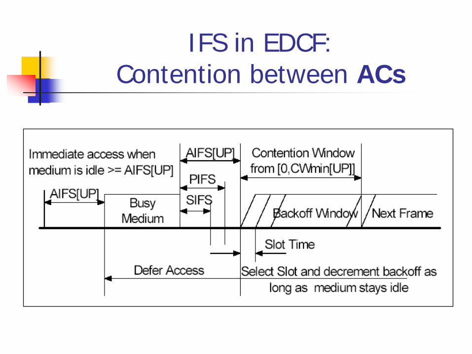
IFS in EDCF:Contention between ACs

IFS in EDCF:Contention between ACs
AIFS[UP] > SIFS to protect Acknowledgement (ACK) transmission
AIFS[UP] and CWmin[UP] announced by AP in beacon frames
SIFS 2 slots
2 slots
3 slots
7 slots
0 ~ 3 slots
0 ~ 7 slots
0 ~ 15 slots
0 ~ 15 slots
Voice
Video
BestEffort
Back-ground
Random BackoffWait
MinimumWait
Assumptions: WME Default Parameters Backoff values shown are for
initial CW equal to CWmin = 15
AIFSN
AIFSN
AIFSN
AIFSN
SIFS
SIFS
SIFS

Arbitration Interframe Space (AIFS)
QSTA use AIFS to defer the contention window or transmission for each AC
AIFS[AC] = AIFSN[AC] x aSlotTime + aSIFTime AIFSN (space number) for each AC is
broadcast via beacon frame containing ‘EDCA Parameter Set’ element

EDCF Multiple Queues Multiple FIFO queues in the MAC: up to 4 queues Every queue is an independent contention entity with
its own contention parameters
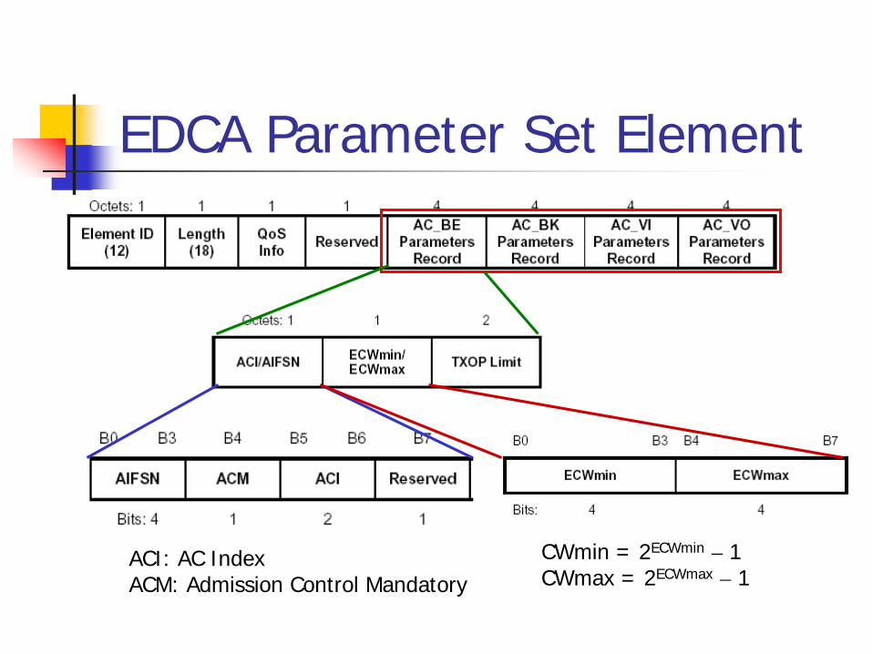
EDCA Parameter Set Element
ACI: AC IndexACM: Admission Control Mandatory
CWmin = 2ECWmin – 1CWmax = 2ECWmax – 1
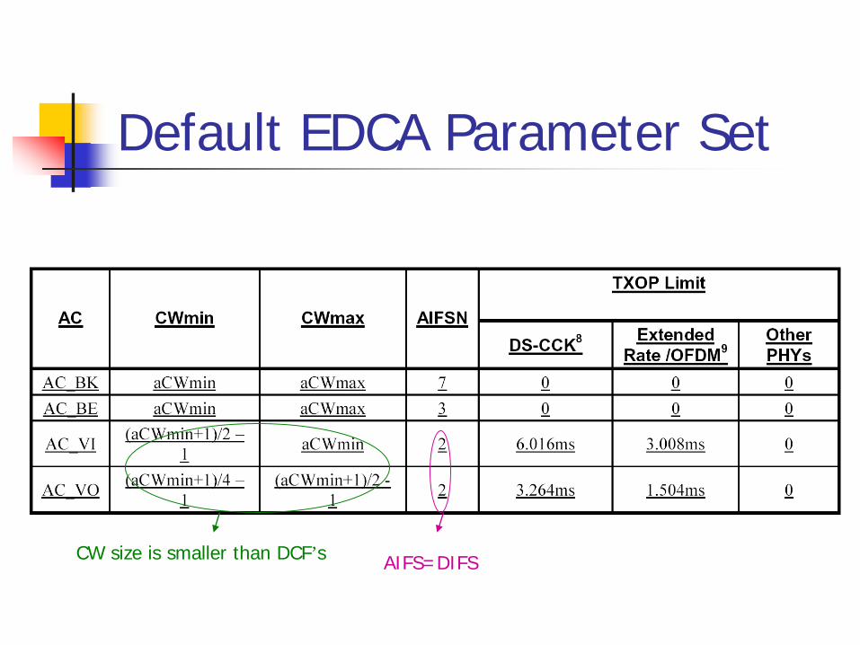
Default EDCA Parameter Set
AIFS=DIFSCW size is smaller than DCF’s

Example AIFS[AC1] –AIFS[AC3] = 2

HCF Controlled Channel Access (HCCA) The procedure is similar to PCF Hybrid Coordinator (HC)
Operate at QAP Control the iteration of CFP and CP
By using beacon and CF-End frame and NAV Mechanism (Same as PCF)
Use polling Scheme to assign TXOP to QSTA Issue QoS (+) CF-poll frame to poll QSTA Polling schedule in HC is calculated according to TSPECs

Iteration of CFP and CPSuperframe
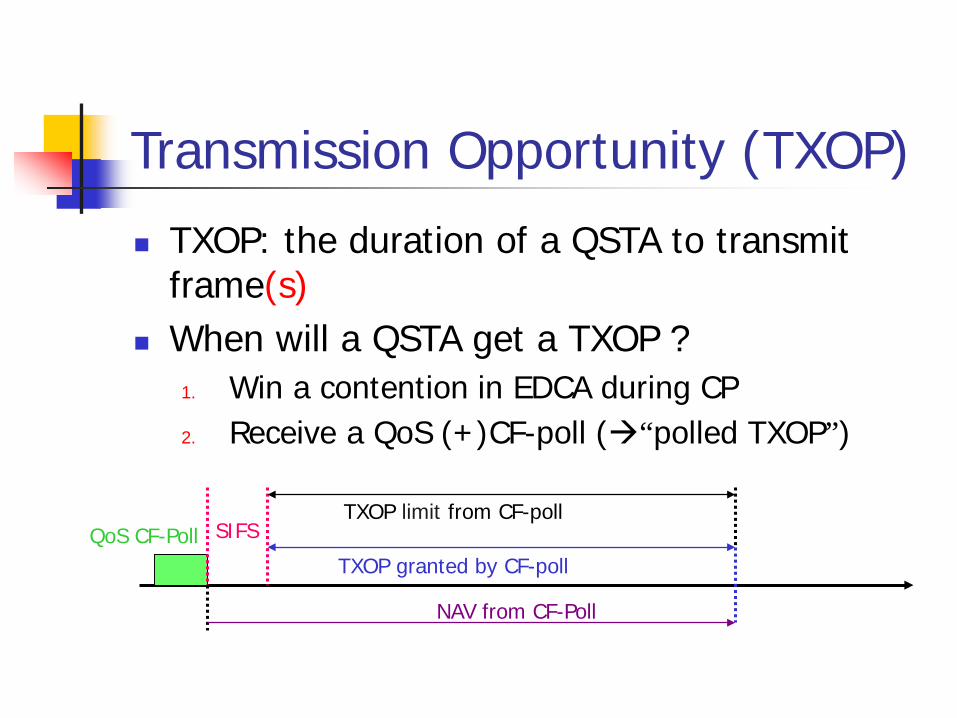
Transmission Opportunity (TXOP) TXOP: the duration of a QSTA to transmit
frame(s) When will a QSTA get a TXOP ?
1. Win a contention in EDCA during CP2. Receive a QoS (+)CF-poll (“polled TXOP”)
QoS CF-Poll SIFSTXOP granted by CF-poll
TXOP limit from CF-poll
NAV from CF-Poll
Transmission Opportunity (TXOP) (cont.) In TXOP, frames exchange sequences are
separated by SIFS How is TXOP limit given
For EDCA, TXOP limit is given in Beacon Frame (at EDCA Parameter Set Element in frame body) pp.41
For controlled channel access, TXOP limit is given in QoS (+)CF-poll frames (at QoS Control field in MAC header) pp.19

Superframe
Beacon
CF-PollCF-End
802.11 periodic Superframe
DATA DATA DATA
CFP(Contention Free Period) CP(Contention Period)
DATA DATA DATA
PC
STAs
802.11e periodic Superframe
Beacon DATA DATA DATA
CFP(Contention Free Period)(Polling through HCF)
CP(Contention Period)
DATA DATA DATA DATA
HC
STAs
TXOP
CF-Poll
DATA
PolledTXOP
DATA
EDCATXOP
EDCATXOP
PolledTXOP
PolledTXOP
Direct Link Protocol (DLP)
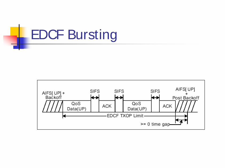
EDCF Bursting
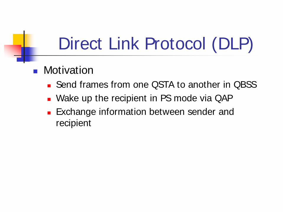
Direct Link Protocol (DLP) Motivation
Send frames from one QSTA to another in QBSS Wake up the recipient in PS mode via QAP Exchange information between sender and
recipient

The handshake procedure QAP
Sender Recipient
(1a) (1b)
(2a)(2b)
Notes:1. The direct link will become inactive if no frames have been
exchanged for DLPTimeoutValue duration.2. Recipient shall not go into power save for DLPTimeoutValue
duration.3. After timeout, the frames are transmitted via AP again.

DLP

DLP

Brief of Block ACK Improve channel efficiency
By aggregating several ACKs into one frame
Two types Immediate Block ACK
Suitable for High-bandwidth, low latency traffic Delayed Block ACK
Suitable for applications tolerating moderate latency

Procedure of Block Ack
Originator Recipient
ADDBA RequestACK
ADDBA ResponseACK
Setup
QoS Data MPDU
BlockAckReq
…
BlockAck
Data &Burst Ack
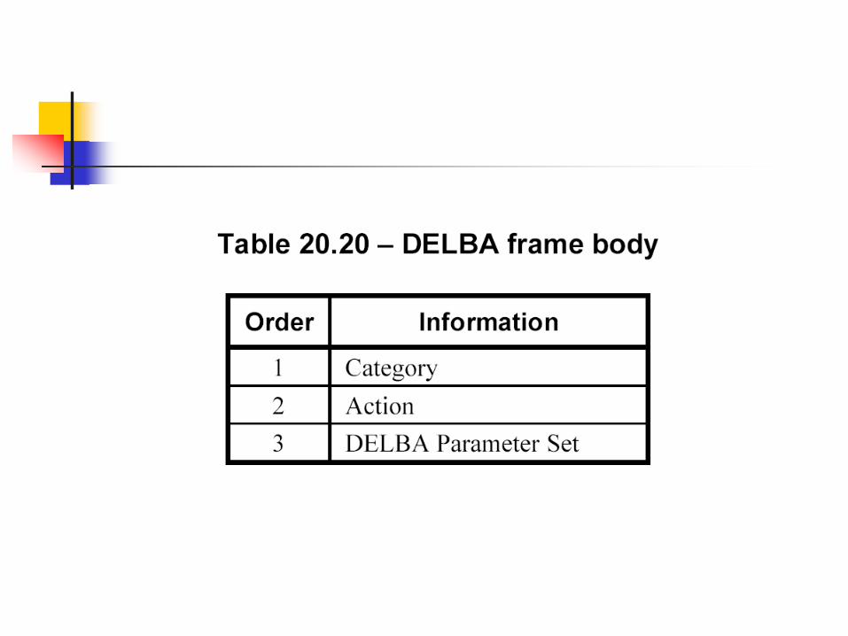
DELBA RequestACK
Tear Down XXX: Action frameXXX: Control Frame
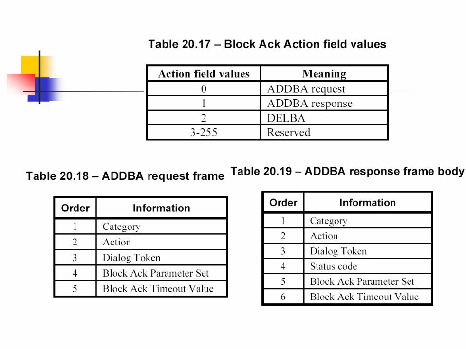

Setup Burst Ack Parameters Action Frames (Management frames)
ADDBA Request, with parameters TID Block Ack Policy (Immediate or delayed) Transmit Buffer Size Timeout Value
ADDBA Response, with parameters Status Code Burst Ack Policy (1 for Immediate, 0 for Delayed) TID Re-ordering Burst Size (number of buffers) Timeout value
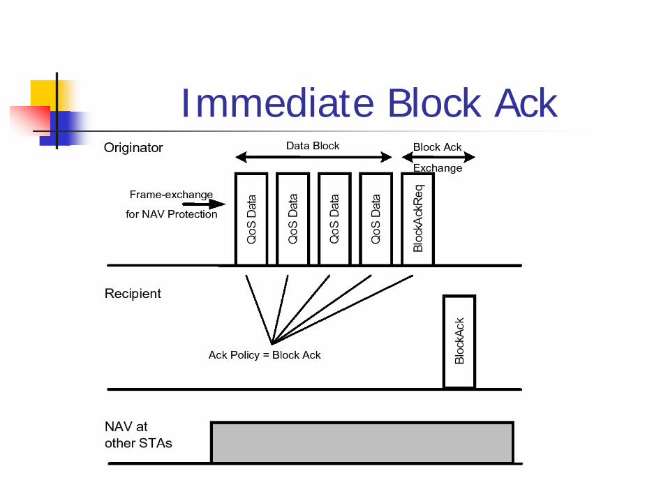
Immediate Block Ack

Delayed Block Ack

BlockAckReq Frame Format

BlockAck Frame Format
Is used to indicate the receiving status of up to 64 MSDUs Bit position n acknowledges receipt of an MPDU with Sequence
control value (Block Ack Starting Sequence Control + n)

Frame usage
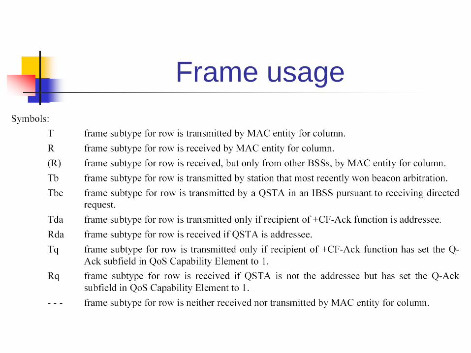
Frame usage
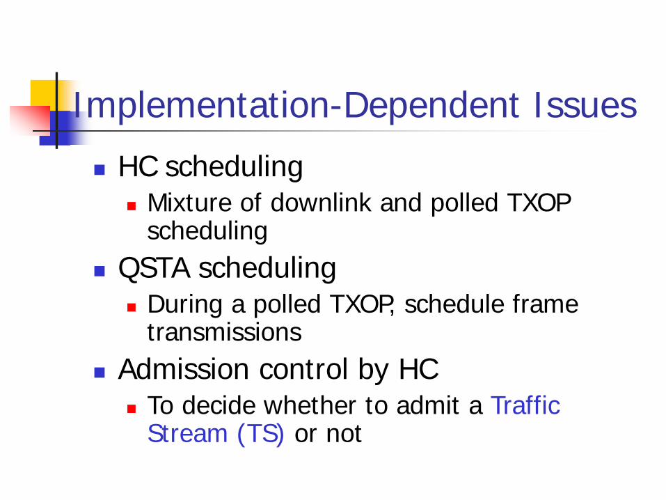
Implementation-Dependent Issues HC scheduling
Mixture of downlink and polled TXOP scheduling
QSTA scheduling During a polled TXOP, schedule frame
transmissions Admission control by HC
To decide whether to admit a Traffic Stream (TS) or not
Power Management Two Power Management Approaches in
802.11e U-ASPD (WMM)
Unscheduled Automatic Power Save Delivery Based on EDCA
S-ASPD Scheduled Automatic Power Save Delivery Based on HCCA

Comparison with Legacy Power Save
Refer from WMM
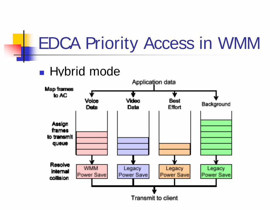
EDCA Priority Access in WMM Hybrid mode
TIM for Legacy Power Saving Trigger mode for WMM Power Saving
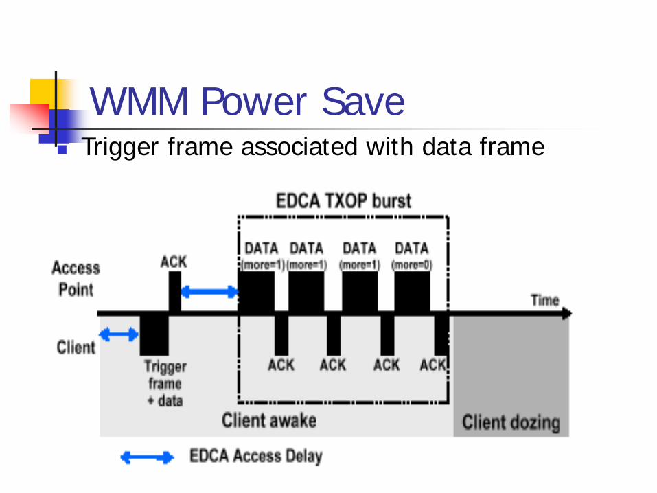
WMM Power Save Trigger frame associated with data frame

Study Case: VoIP Less than 20 ms delay is required More than 20 ms delay will make voice hard to be
understood. Beacon Interval is assumed to be 100ms
VoIP is not work in legacy power management mode

Comparisons In legacy configuration, the client waits for
the beacon frame before it initiates the downlink data transmission. It will delay 100 ms to 300 ms.
In WMM Power save, every 20 ms, The access point buffers all the voice frames to be delivered until it receives a trigger frame from the client.
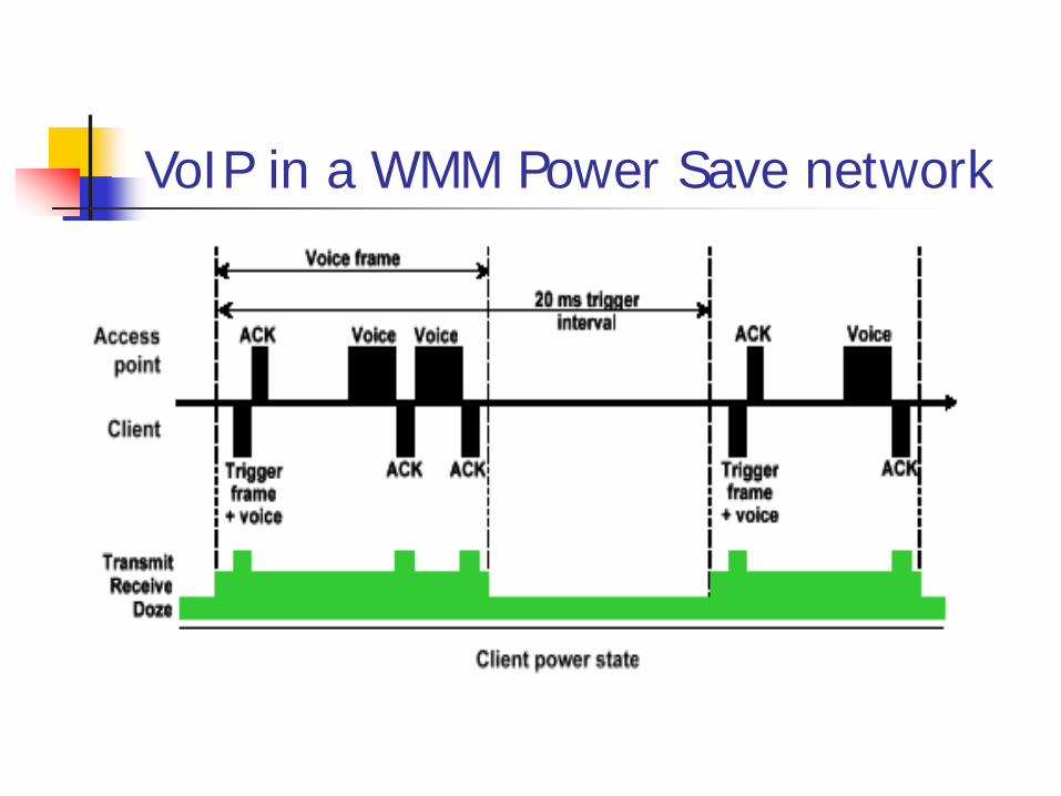
VoIP in a WMM Power Save network
Thank You!
Q & A