study of mobility and qos of 802.11 and 802.11e wireless lan
TRANSCRIPT

Study of mobility and QoS of 802.11 and 802.11e Wireless LAN standards
FEDOUA DIDI University Abou Bekr Belkaid of Tlemcen ALGERIA
[email protected]@YAHOO.FR
HOUDA LABIOD
ENST of Paris FRANCE [email protected]
GUY PUJOLLE
LIP6 of University Pierre and Marie Currie FRANCE [email protected]
MOHAMED FEHAM
University Abou Bekr Belkaid of Tlemcen ALGERIA [email protected]
Abstract Quality of service (QoS) is a key problem in wireless environments where bandwidth is scarce and channel conditions are time varying and sometimes highly loss. Although IEEE 802.11 wireless LAN (WLAN) is the most widely used WLAN standard today, and the upcoming IEEE 802.11e QoS enhancement standard exists and introduces the QoS for supporting multimedia applications. This paper compares the propositions of standard IEEE 802.11e with the standard IEEE 802.11 without QoS, a simulation of these standards is performed by using the NS simulator. We test also the mobility and the roaming of stations. A discussion is presented in detail using simulation-based evaluations and we let us confirm the QoS of IEEE 802.11e compared to IEEE 802.11, but we have detected some weaknesses of 802.11e. It starves the low priority traffic in case of high load, and leads to higher collision rates, and did not make a good estimate of weight of queues, so there is an unbalance enters the flows with high priorities.
Keywords: IEEE 802.11, Medium Access Control (MAC), Quality of Service (QoS), Distributed Coordination Function (DCF), Point Coordination Function (PCF), Hybrid Coordination Function (HCF), IEEE 802.11e, Network Simulator (NS)
1 Introduction IEEE 802.11 wireless LAN (WLAN) [1] is one of the most deployed wireless technologies all over the world and is likely to play a major role in next generation wireless communications networks. The main characteristics of 802.11WLAN technology are simplicity, flexibility, mobility and cost effectiveness. This technology provides people with a ubiquitous communications and computing environment in offices, hospitals, campuses, factories, airports, stock markets, etc. Simultaneously, multimedia applications have experienced an explosive growth. People are now requiring receiving high speed video, audio, voice and Web services even when they are moving in offices or travelling around campuses. However, multimedia applications require some quality of service support such as guaranteed bandwidth,
delay, jitter and error rate. Guaranteeing those QoS requirements in 802.11 WLAN is very challenging due to the QoS unaware functions of its medium access control (MAC) layer and the noisy and variable physical (PHY) layer characteristics. In this paper we compare the two standards 802.11 and 802.11e to look at their QoS, mobility and roaming, by using a simulation with Network Simulator (NS) and present a detailed discussion of results. The paper is organized as follows. Section 2 introduces an overview of IEEE 802.11 WLAN and section 3 introduces the QoS enhancement standard 802.11e. In section 4, we present the model of simulation with its parameters and a detailed discussion of results.
31 African Journal of Information and Communication Technology, Vol. 4, No. 2, June 2008
1449-2679/$00 - (C) 2006 AJICT. All rights reserved.
2 Description of 802.11 standard The IEEE 802.11 WLAN standard covers the MAC sub-layer and the physical (PHY) layer of the open system interconnection (OSI) network reference model [1]. Logical link control (LLC) sub-layer is specified in the IEEE 802.2 standard. This architecture provides a transparent interface to the higher layer users: stations (STAs) may move, roam through an 802.11 WLAN and still appear as stationary to 802.2 LLC sub-layer and above. This allows existing TCP/IP protocols to run over IEEE 802.11 WLAN just like wired Ethernet deployed. We can show [3] different standardization activities done at IEEE 802.11 PHY and MAC layers. The standard comprises three PHY layers, which are an InfraRed (IR) base band PHY; a frequency hopping spread spectrum (FHSS) radio and direct sequence spread spectrum (DSSS) radio. These entire choices support both 1 and 2Mbps PHY rate. In 1999, the IEEE define two high rate: 802.11b in the 2.4GHz band with 11Mbps, based on DSSS technology; and 802.11a in the 5GHz band with 54Mbps, based on orthogonal frequency division multiplexing (OFDM) technology. Recently, 802.11g is finalized to be an extension of 802.11b with 54Mbps in the 2.4GHz band.
2.1 The MAC sub-layer of 802.11 It defines two medium access coordination functions, the basic Distributed Coordination Function (DCF) and the optional Point Coordination Function (PCF) [1]. Asynchronous transmission is provided by DCF which operate in contention-based period, and synchronous transmission is provided by PCF that basically implements a polling-based access which operate in contention free period. A group of STAs coordinated by DCF or PCF is formally called a basic set (BSS). The area covered by BSS is the basic service area (BSA), like a cell in a cellular mobile network. Two modes exist: ad-hoc mode and infrastructure mode. The first mode forms an Independent BSS (IBSS) where the STAs can directly communicate with each other by using only the DCF, without any connectivity to any wired backbone. In the second mode, the STAs communicate with the wired backbone through the bridge of access point (AP), which can use both DCF and PCF.
2.1.1 Distributed Coordination Function
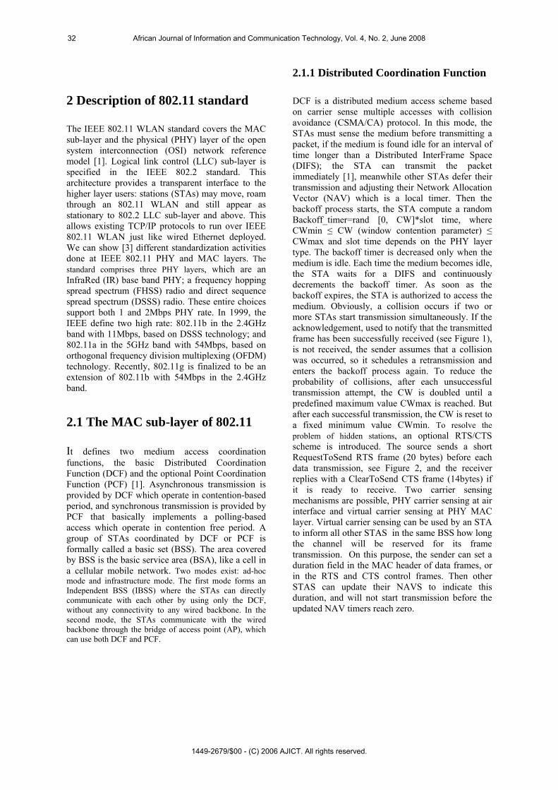
DCF is a distributed medium access scheme based on carrier sense multiple accesses with collision avoidance (CSMA/CA) protocol. In this mode, the STAs must sense the medium before transmitting a packet, if the medium is found idle for an interval of time longer than a Distributed InterFrame Space (DIFS); the STA can transmit the packet immediately [1], meanwhile other STAs defer their transmission and adjusting their Network Allocation Vector (NAV) which is a local timer. Then the backoff process starts, the STA compute a random Backoff_timer=rand [0, CW]*slot time, where CWmin ≤ CW (window contention parameter) ≤ CWmax and slot time depends on the PHY layer type. The backoff timer is decreased only when the medium is idle. Each time the medium becomes idle, the STA waits for a DIFS and continuously decrements the backoff timer. As soon as the backoff expires, the STA is authorized to access the medium. Obviously, a collision occurs if two or more STAs start transmission simultaneously. If the acknowledgement, used to notify that the transmitted frame has been successfully received (see Figure 1), is not received, the sender assumes that a collision was occurred, so it schedules a retransmission and enters the backoff process again. To reduce the probability of collisions, after each unsuccessful transmission attempt, the CW is doubled until a predefined maximum value CWmax is reached. But after each successful transmission, the CW is reset to a fixed minimum value CWmin. To resolve the problem of hidden stations, an optional RTS/CTS scheme is introduced. The source sends a short RequestToSend RTS frame (20 bytes) before each data transmission, see Figure 2, and the receiver replies with a ClearToSend CTS frame (14bytes) if it is ready to receive. Two carrier sensing mechanisms are possible, PHY carrier sensing at air interface and virtual carrier sensing at PHY MAC layer. Virtual carrier sensing can be used by an STA to inform all other STAS in the same BSS how long the channel will be reserved for its frame transmission. On this purpose, the sender can set a duration field in the MAC header of data frames, or in the RTS and CTS control frames. Then other STAS can update their NAVS to indicate this duration, and will not start transmission before the updated NAV timers reach zero.
32 African Journal of Information and Communication Technology, Vol. 4, No. 2, June 2008
1449-2679/$00 - (C) 2006 AJICT. All rights reserved.
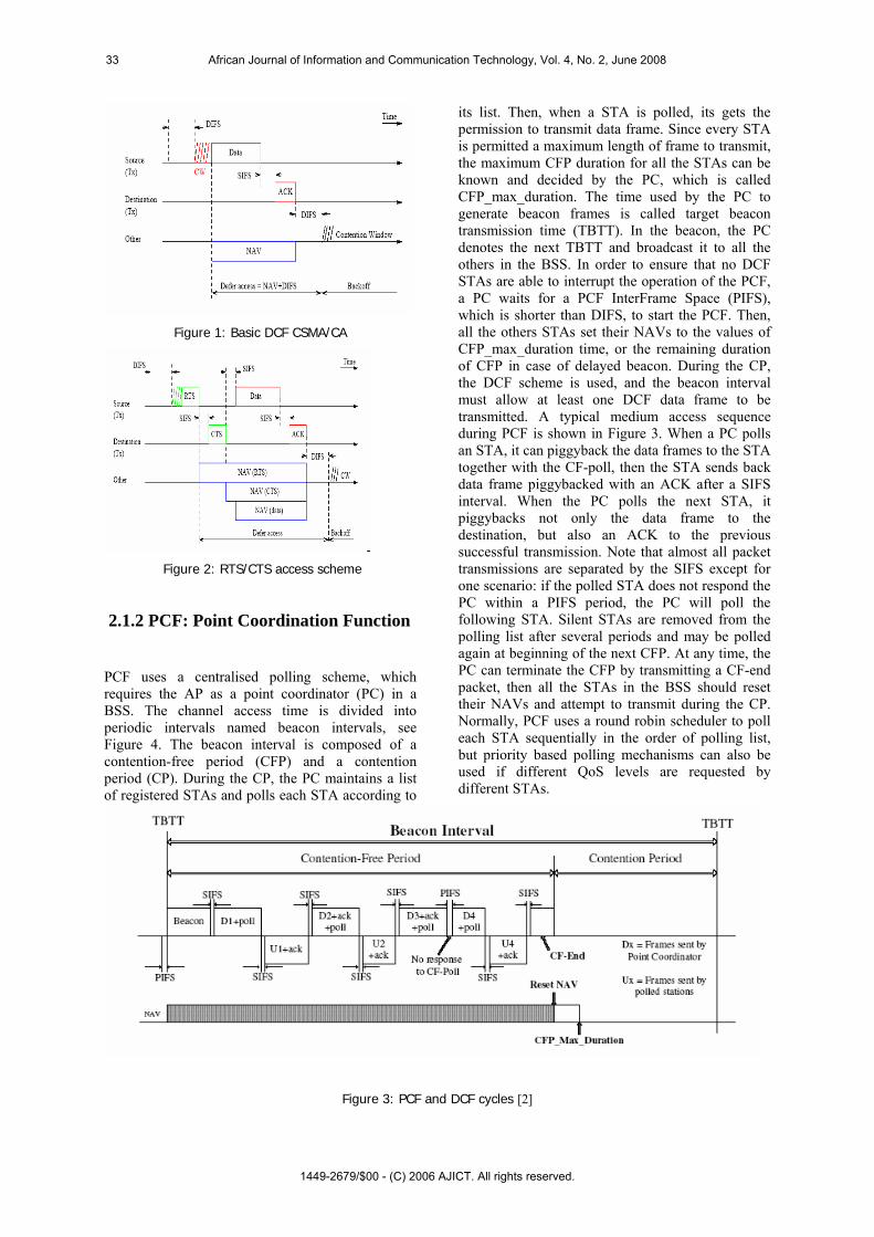
Figure 1: Basic DCF CSMA/CA
Figure 2: RTS/CTS access scheme
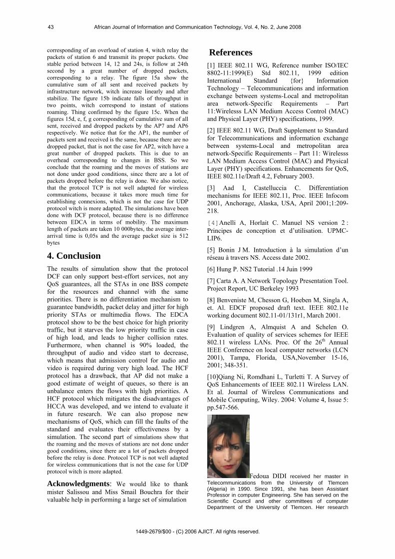
2.1.2 PCF: Point Coordination Function PCF uses a centralised polling scheme, which requires the AP as a point coordinator (PC) in a BSS. The channel access time is divided into periodic intervals named beacon intervals, see Figure 4. The beacon interval is composed of a contention-free period (CFP) and a contention period (CP). During the CP, the PC maintains a list of registered STAs and polls each STA according to
its list. Then, when a STA is polled, its gets the permission to transmit data frame. Since every STA is permitted a maximum length of frame to transmit, the maximum CFP duration for all the STAs can be known and decided by the PC, which is called CFP_max_duration. The time used by the PC to generate beacon frames is called target beacon transmission time (TBTT). In the beacon, the PC denotes the next TBTT and broadcast it to all the others in the BSS. In order to ensure that no DCF STAs are able to interrupt the operation of the PCF, a PC waits for a PCF InterFrame Space (PIFS), which is shorter than DIFS, to start the PCF. Then, all the others STAs set their NAVs to the values of CFP_max_duration time, or the remaining duration of CFP in case of delayed beacon. During the CP, the DCF scheme is used, and the beacon interval must allow at least one DCF data frame to be transmitted. A typical medium access sequence during PCF is shown in Figure 3. When a PC polls an STA, it can piggyback the data frames to the STA together with the CF-poll, then the STA sends back data frame piggybacked with an ACK after a SIFS interval. When the PC polls the next STA, it piggybacks not only the data frame to the destination, but also an ACK to the previous successful transmission. Note that almost all packet transmissions are separated by the SIFS except for one scenario: if the polled STA does not respond the PC within a PIFS period, the PC will poll the following STA. Silent STAs are removed from the polling list after several periods and may be polled again at beginning of the next CFP. At any time, the PC can terminate the CFP by transmitting a CF-end packet, then all the STAs in the BSS should reset their NAVs and attempt to transmit during the CP. Normally, PCF uses a round robin scheduler to poll each STA sequentially in the order of polling list, but priority based polling mechanisms can also be used if different QoS levels are requested by different STAs.
Figure 3: PCF and DCF cycles [2]
33 African Journal of Information and Communication Technology, Vol. 4, No. 2, June 2008
1449-2679/$00 - (C) 2006 AJICT. All rights reserved.

3 Description of 802.11e standard 3.1 HCF: Hybrid Coordination Function There are many new features in 802.11e draft 4.2 [2]. In this section, we will briefly describe HCF. HCF is composed of two access methods: contention-based channel access (called EDCA) and controlled channel access mechanisms. One main feature of HCF is to introduce four access category (AC) queues and eight traffic stream (TS) queues at MAC layer. When a frame arrives at MAC layer, it is tagged with a traffic priority identifier (TID) according to its QoS requirements. Which can take the values from 0 to 15? The frames with TID values from 0 to 7 are mapped into four AC queues using EDCA access rule. On the other hand, frames with TID values from 8 to 15 are mapped into eight TS queues using HCF controlled channel access rule. The reason of separating TS queues from AC queues is to support strict parameterized QoS at TS queues while prioritized QoS is supported at AC queues. Another main feature of the HCF is the concept of transmission opportunity (TXOP), which is the time interval permitted, for a particular STA to transmit packets. During the TXOP, there can be a series of frames transmitted by an STA separated by SIFS. The TXOP is called either EDCA-TXOP, when it is obtained by winning a successful EDCA contention; or polled-TXOP, when it is obtained by receiving a QoS CF-poll frame from the QoS-enhanced QP (QAP). The maximum value of TXOP is called TXOPLimit, which is determined by QAP.
3.2 Enhanced Distributed Coordination Function (EDCA) The EDCA is designed for the contention-based prioritized QoS support. Figure 4 shows that in EDCA, each QoS-enhanced STA (QSTA) has 4 queues (ACs), to support 8 user priorities (UPs). Therefore, one or more UPs are mapped to the same AC queue, see Figure 5. This comes from the observation that usually eight kinds of applications do not transmit frames simultaneously, and using less ACs than UPs reduces the MAC layer overheads. Each AC queue works as an independent DCF STA and uses its own backoff parameters.
The first one uses different InterFrame Space (IFS) sizes for different ACs. Figure 6 shows the detailed timing diagram of the EDCA scheme. A new kind of IFS called Arbitrary IFS (AIFS) is used in EDCA, instead of DIFS in DCF. AIFS [AC] = AIFSN [AC] * SlotTime + SIFS, where the default value of the arbitration inter frame spacing number (AIFSN) is defined as either 1 or 2 [2].When AIFSN=1, high priority queues AC1, AC2 and AC3 have AIFS value equal to PIFS. When AIFSN=2, the low priority queue AC0 has AIFS value of DIFS. When a frame arrives at an empty AC queue and the medium has been idle longer than AIFS [AC] +SlotTime, the frame is transmitted immediately. If the channel is busy, the arriving packet in each AC has to wait until the medium becomes idle and then defer for AIFS+SlotTime. So the AC with the smaller AIFS has the higher priority. For example, the earliest transmission time for high priority queue is to wait for PIFS+SlotTime=DIFS, while the earliest transmission time for best effort queue is to wait for DIFS+ SlotTime.
The second method consists in allocating different CW sizes for different ACs. Assigning a short CWsize to high priority AC ensures that in most cases, high-priority AC is able to transmit packets ahead of low-priority one. If the backoff counters of two or more parallel ACs in one QSTA reach zero at the same time, a scheduler inside the QSTA will avoid the virtual collision by granting the EDCA-TXOP to the highest priority AC. At the same time, the other colliding ACs will enter a backoff process and double the CW sizes as if there is an external collision. In this way, EDCA is supposed to improve the performance of DCF under congested conditions. The default values of AIFSN [AC], CWmin [AC], CWmax [AC] and TXOPLimit [AC] are announced by the QAP in beacon frames, and the 802.11e standard also allows the QAP to adapt these parameters dynamically depending on network conditions [2]. But how to adapt to the channel has not been defined by the standard and remains an open research issue.
34 African Journal of Information and Communication Technology, Vol. 4, No. 2, June 2008
1449-2679/$00 - (C) 2006 AJICT. All rights reserved.

Figure 4: EDCA proposed by 802.11e
Figure 5: Mapping between UP and AC
Figure 6: EDCA channel access IFS Relationships [2]
To improve the throughput performance, EDCA packet bursting can be used in 802.11e, meaning that once a QSTA has gained an EDCA-TXOP, it can be allowed to send more than one frame without contending for the medium again. After getting access to the medium, the QSTA can send multiple frames as long as the total access time does not exceed the TXOPLimit bound determined by QAP. To ensure that no other QSTA interrupts the packet
bursting, SIFS is used between packet bursts. If a collision occurs; the EDCA bursting is terminated. This mechanism can reduce the network overhead and increase throughput by multiple transmissions using SIFS and burst acknowledgements. However, bursting may also increase the jitter, so TXOPLimit should not be longer than the time required for the transmission of the largest data frame.
3.3 HCF controlled channel access The HCF controlled channel access mechanism (HCCA) is designed for the parameterized QoS support, which combines the advantages of PCF and DCF. HCCA can start the controlled channel access mechanism in both CFP and CP intervals, whereas PCF is only allowed in CFP. Figure 7 is an example of typical 802.11e beacon interval, which is composed of alternated modes of optional CFP and CP. During the CP, a new contention-free period named controlled access phase (CAP) is introduced. CAPs are several intervals during which frames are transmitted using HCCA. HCCA can start a CAP by sending downlink QoS-frames or QoS CP-Poll frames to allocate polled-TXOP to different QSTAs after the medium remains idle for at least PIFS interval. Then the remaining time of the CP can be used by EDCA. This flexible contention-free scheme makes PCF and CFP useless and thus optional in the 802.11e standard. By using CAP, the HCF beacon interval size can be independent of targeted delay bounds of multimedia applications. For example, in order to support audio traffic with a maximum latency of 20 millisecond (ms) using PCF, the beacon interval should be no more than 20 ms since the fixed portion of CP forces the audio traffic to wait for the next poll. On the other hand, the HCCA can increase the polling frequency by initiating CAP at any time, thus guarantee the delay bound with any size of beacon interval. So there is no need to reduce the beacon interval size that increases the overheads. Moreover, the problem of beacon delay in PCF is solved, because in HCF, a QSTA is not allowed to transmit a frame if the transmission cannot be finished before the next TBTT.
Figure 7: A typical 802.11e HCF beacon interval
35 African Journal of Information and Communication Technology, Vol. 4, No. 2, June 2008
1449-2679/$00 - (C) 2006 AJICT. All rights reserved.

In HCCA, QoS guarantee is based on the traffic specification (TSPEC) negotiation between the QAP and the QSTAs. Before transmitting any frame that requires the parameterized QoS, a virtual connection called traffic stream (TS) is established. In order to set up a TS, a set of TSPEC parameters (such as mean data rate, nominal frame size, maximum service interval, delay bound, etc.) are exchanged between the QAP and the corresponding QSTAs. Based on these TSPEC parameters, the QAP scheduler computes the duration of polled-TXOP for each QSTA, and allocates the polled-TXOP to each QSTA. Then the scheduler in each QSTA allocates the TXOP for different TS queue according to the priority order. A simple round-robin scheduler is proposed in the IEEE 802.11e draft 4.2 [2,3]. The simple scheduler uses the following mandatory TSPEC parameters: mean data rate, nominal MAC frame size and maximum service interval or delay bound. Note that the maximum service interval requirement of each TS corresponds to the maximum time interval between the start of two successive TXOPs. If this value is small, it can provide low delay but introduce more CF-Poll frames. If different TS have different maximum service interval requirements, the scheduler will select the minimum value of all maximum service interval requests of all admitted streams for scheduling. Moreover, the QAP is allowed to use an admission control algorithm to determine whether or not to allow new TS into its BSS. When a TS is set
up, the QAP attempts to provide QoS by allocating the required bandwidth to the TS. During a CFP, the medium is fully controlled by QAP. During a CP, it can also grab the medium whenever it wants (after a PIFS idle time). After receiving a QoS CF-poll frame, a polled QSTA is allowed to transmit multiple MAC frames denoted by contention-free burst (CFB), with the total access time not exceeding the TXOPLimit. All the other QSTAs set their NAVs with the TXOPLimit plus a slot time. By this way, they will not contend for the medium during that period. If there are no frames to be sent to the QAP, the polled QSTA will send a QoS-Null frame to the QAP which can poll another QSTA.
4 Simulation-based evaluations of QoS-enhanced schemes
In [8-10], different simulations have been conducted with different topology and parameters of EDCA. To evaluate the performance of DCF and EDCA schemes, we consider the topology shown in Figure 8 and uses NS-2 [4-7], there is no mobility in the system, each station operates at IEEE 802.11b PHY and transmits three types of traffic (audio, video and data traffic) to each other. The EDCA and DCF MAC parameters are listed in Table 1 and 2. We use RTP/UDP/IP traffic sources. We vary the load rate by increasing the number of STAs from 0 to 6.
Ad hoc mode (DCF) Wired network
AP
Infrastructure mode
(PCF)
Figure 8: Simulation Topology used (DCF and EDCF)
36 African Journal of Information and Communication Technology, Vol. 4, No. 2, June 2008
1449-2679/$00 - (C) 2006 AJICT. All rights reserved.

Table 1: EDCA parameters Table 2: DCF parameters
Parameters Audio PCM Vidéo MPEG4
Vidéo VBR Data
CWmin 7 15 15 31
CWmax 15 31 31 1023
AIFSN 1 1 2 2
Packet Size (Bytes)
160 1280 660 1600
Packet Interval
(ms)
20 16 26 12.5
Sending Rate
(KB/s)
8 80 25 128
Figure 9 shows the simulation results for the bandwidth, and latency. We can see that average throughput of three kinds of flows per STA are stable and sufficient as long as the channel load rate is less than 70% at the 25th second, but after all flows degrade themselves dramatically in DCF, and not in EDCA. And we note that there is a high rate loss of packets in DCF, and a low rate loss of
packets in EDCA. We see also that latency is low for all flows, but at the 25th second, it increases significantly in DCF. On the other hand, in EDCA only data suffer by a high latency. The latency increases in DCF, in function of channel load rate is dramatic for all flows after 70% rate, but in EDCA after 60% only data flow degrade themselves.
Figure 9: Throughput and latency performance for DCF and EDCA
SIFS 16µs MAC header 28bytes
DIFS 34µs PLCP header length
4µs
ACK size
14bytes Preamble length 20µs
PHY rate
36Mbps CWmin 15
Slot time
9µs WCmax 1023
37 African Journal of Information and Communication Technology, Vol. 4, No. 2, June 2008
1449-2679/$00 - (C) 2006 AJICT. All rights reserved.

Figure 10 and 11 shows the advantages of HCCA compared to EDCA, we simulate a topology with 13 STAs (STA 0 is the AP), six STAs transmit each one an audio flow, and the six others transmit a video flow (CBR MPEG4) at AP. We notice that the throughput (D) is stable and distributed well on all the STAs by HCF, which is not the case for EDCA, where D fluctuate too much quickly, what indicates a bad management of the bandwidth. For EDCA, the latency increases all gently when the channel load rate increases but only for audio flows, for the video flows, the latency increase brutally. For HCCA, the evolution of latency is the same for all flows. Figure 12 shows the limitations of HCCA by a simulation of 19 STAs (the STA 0 is the AP) and STA1 to
STA6 transmits a PCM Audio flows with inter arrival time of 4.7ms, Packet size of 160bytes, Sending rate of 64Kbps and a priority of 6. STA7 to STA12 transmits VBR (variable bit rate) video flows with Arrival period almost equal to 26, Packet size almost equal to 660, Sending rate almost equal to 200 and a priority of 5. STA13 to STA18 transmits a MPEG4 video flows with Arrival period=2, Packet size=800, Sending rate=3200 and a priority of 4. Let us notice that latency of VBR flows fluctuate and increase dramatically, which is not the case of the other flows. This is due to the fact that the AP is unable to make a good estimatation of the size of the queues for a fair scheduling.
Figure 10 Throughput for EDCA and HCF Controlled channel access
Figure 11: Channel load versus latency for EDCA and HCCA
38 African Journal of Information and Communication Technology, Vol. 4, No. 2, June 2008
1449-2679/$00 - (C) 2006 AJICT. All rights reserved.

Figure 12: Latency and evolution of latency for HCCA
To simulate the mobility of stations, we use an IBSS of seven mobiles stations (number 0 to 6) in ad hoc mode by using the DCF protocol and the stations number 3 and 4 like see in the figure 13 move. Another network with two AP (two BSS) of 13 nodes, stations number 0 to 5 are wired stations and connected with the two AP numbers 6 and 7. We have also five mobiles stations numbered for 8 to 12, all move by changing BSS (roaming), like see in figure 13. We use data communications within scenario like noted in the table 3 for the first topology and table 4 for the second topology.
Table 3 Scenario for the first topology
Commu
nication
Start of
comm
End of
comm
Trans
proto
Type of
comm
5 to 2 4,12 13,12 TCP Direct
1 to 4 7,00 17,00 UDP Direct
6 to 0 10,02 14,12 TCP Use relay
Sta 4
6 to 2 16,00 20,00 UDP Direct
4 to 5 18,00 24,00 UDP Direct
3 to 6 20,02 30,00 TCP Direct and
At 24s, sta 1
relay
Table 4 Scenario for the second topology
Commu
nication
Start of
comm
End of
comm
Trans
Proto
Type of
comm
1 to 8 0,02s 4,12s TCP By use
AP6
4 to 11 5,15s 20,15s TCP By use
AP7,and at
12,45 by AP6
Roaming
5 to 12 14,1s 35,0s UDP By use AP7
3 to 9 21,0s 35,0s UDP By use AP7
And by AP6
Roaming
39 African Journal of Information and Communication Technology, Vol. 4, No. 2, June 2008
1449-2679/$00 - (C) 2006 AJICT. All rights reserved.

Figure 13 Topology of simulated networks
(a) (b)
40 African Journal of Information and Communication Technology, Vol. 4, No. 2, June 2008
1449-2679/$00 - (C) 2006 AJICT. All rights reserved.

(d) e first topology (stations in moving)
(a) (b)
(c)
(c) Figure 14 Simulation Results of th
41 African Journal of Information and Communication Technology, Vol. 4, No. 2, June 2008
1449-2679/$00 - (C) 2006 AJICT. All rights reserved.

(e)
(f) (g)
Figure 15 Simulation Results of the second topology (stations in roaming)
The figure 14a, witch represents the cumulative sum of all sent and received packets by network, show that it increase quickly, after it stabilize between 14,2s and 20,02s because there is only one communication in the network, after it increase, thing completely normal. The
figure 14b, witch represents the throughput for sending packets (packets per s), show that for the two periods between 14-16s and 24-26s, there are brutal falls of throughput, corresponding to moves of the stations 6 and 3 and use of intermediate stations like relay. The figure 14c, witch represents the cumulative sum of dropped packet, show a light increase, follow by a stronger one
(d)
42 African Journal of Information and Communication Technology, Vol. 4, No. 2, June 2008
1449-2679/$00 - (C) 2006 AJICT. All rights reserved.
corresponding of an overload of station 4, witch relay the packets of station 6 and transmit its proper packets. One stable period between 14, 12 and 24s, is follow at 24th second by a great number of dropped packets, corresponding to a relay. The figure 15a show the cumulative sum of all sent and received packets by infrastructure network, witch increase linearly and after stabilize. The figure 15b indicate falls of throughput in two points, witch correspond to instant of stations roaming. Thing confirmed by the figure 15c. When the figures 15d, e, f, g corresponding of cumulative sum of all sent, received and dropped packets by the AP7 and AP6 respectively. We notice that for the AP1, the number of packets sent and received is the same, because there are no dropped packet, that is not the case for AP2, witch have a great number of dropped packets. This is due to an overhead corresponding to changes in BSS. So we conclude that the roaming and the moves of stations are not done under good conditions, since there are a lot of packets dropped before the relay is done. We also notice, that the protocol TCP is not well adapted for wireless communications, because it takes more much time for establishing connexions, which is not the case for UDP protocol witch is more adapted. The simulations have been done with DCF protocol, because there is no differencbetween EDCA in terms of mobility. The maximulength of packets are taken 10 000bytes, the average inter-
l time is 0,05s and the average packet size is 512 ytes
. Conclusion The results of simulation show that the protocol DCF can only support best-effort services, not any QoS guarantees, all the STAs in one BSS compete for the resources and channel with the same priorities. There is no differentiation mechanism to guarantee bandwidth, packet delay and jitter for high priority STAs or multimedia flows. The EDCA protocol show to be the best choice for high priority traffic, but it starves the low priority traffic in case of high load, and leads to higher collision rates. Furthermore, when channel is 90% loaded, the throughput of audio and video start to decrease, which means that admission control for audio and video is required during very high load. The HCF protocol has a drawback, that AP did not make a good estimate of weight of queues, so there is an unbalance enters the flows with high priorities. A HCF protocol which mitigates the disadvantages of HCCA was developed, and we intend to evaluate it in future research. We can also propose new mechanisms of QoS, which can fill the faults of the standard and evaluates their effectiveness by a simulation. The second part of simulations show that the roaming and the moves of good conditions, since there abefore the relay i
rotocol witch is more adapted.
References [1] IEEE 802.11 WG, Reference number ISO/IEC 8802-11:1999(E) Std 802.11, 1999 edition International Standard {for} Information Technology – Telecommunications and information exchange between systems-Local and metropolitan area network-Specific Requirements – Part 11:Wirelesss LAN Medium Access Control (MAC) and Physical Layer (PHY) specifications, 1999.
[2] IEEE 802.11 WG, Draft Supplement to Standard for Telecommunications and information exchange between systems-Local and metropolitan area network-Specific Requirements – Part 11: Wirelesss LAN Medium Access Control (MAC) and Physical Layer (PHY) specifications. Enhancements for QoS, IEEE 802.11e/Draft 4.2, February 2003.
[3] Aad I, Castelluccia C. Differentiation mechanisms for IEEE 802.11, Proc. IEEE Infocom 2001, Anchorage, Alaska, USA, April 2001;1:209-218.
[4]Anelli A, Horlait C. Manuel NS version 2 Principes d t d’utilisation. UPMC- LIP6.
[5] Bonin J M. Introduction à la simulation d’un réseau à travers NS. Access date 2002.
[6] Hung P. NS2 Tutorial .14 Juin 1999
[7] Carta A. A Network Topology Presentation Tool. Project Report, UC Berkeley 1993
[8] Benveniste M, Chesson G, Hoeben M, Singla A, et. Al. EDCF proposed draft text. IEEE 802.11e working document 802.11-01/131r1, March 2001.
[9] Lindgren A, Almquist A and Schelen O. Evaluation of quality of services schemes for IEEE 802.11 wireless LANs. Proc. Of the 26th Annual IEEE Conference on local computer networks (LCN 2001), Tampa, Florida, USA,November 15-16, 2001; 348-351.
[10]Qiang Ni, Romdhani L, Turletti T. A Survey of QoS Enhancements of IEEE 802.11 Wireless LAN. Et al. Journal of Wireless Communications and Mobile Computing, Wiley. 2004: Volume 4, Issue 5: pp.547-566.
e m :
arrivab
4
stations are not done under re a lot of packets dropped
s done. Protocol TCP is not well adapted munications that is not the case for UDP for wireless com
p
Acknowledgments: We would like to thank mister Salissou and Miss Smail Bouchra for their valuable help in performing a large set of simulation
e conception e
Fedoua DIDI received her master in Telecommunications from the University of Tlemcen (Algeria) in 1990. Since 1991, she has been Assistant Professor in computer Engineering. She has served on the Scientific Council and other committees of computer Department of the University of Tlemcen. Her research
43 African Journal of Information and Communication Technology, Vol. 4, No. 2, June 2008
1449-2679/$00 - (C) 2006 AJICT. All rights reserved.

interest now is mobile networks and services, QoS service provisioning, performance evaluation, modeling and security of large-scale distributed systems.
Houda LABIOD is an Associate Professor at Department INFRES (Computer Science and Network department) at Telecom ParisTech (previously named ENST) in Paris (France) since 2001. In 2005, she obtained her HDR (Habilitation à diriger les recherches). Prior to this, she held a research position at Eurecom Institute, Sophia-antipolis, France. She obtained her PHD thesis from the University of Versailles Saint-Quentin-en- Yvelines (France) in 1998. Her current research interests include mobile ad hoc networks, wireless LAN networks, sensor networks, wireless mesh networks, NEMO networks, Vehicular communications, QoS service provisioning, performance evaluation, modeling and security of large-scale distributed systems, cross layer design in wireless networks and link adaptation mechanisms. Dr. LABIOD has published four books and research papers in these areas. She is a Founder of NTMS Conference, on New Technologies, Mobility and Security (NTMS2007). She served as an Associate Editor and is on the Editorial Board for COMNET journal.
Guy Pujolle Professor of Paris 6 Guy Pujolle received the Ph.D. and "Thèse d'Etat" degrees in
omputer Science from the niversity of Paris IX and Paris XI
and 1978 respectively.
cations). Guy Pujolle is a pioneer in g having led the development of the
le is
nd wireless
n France for the best scientific book of the year. Guy
.
CUon 1975He is currently a Professor at the University of Paris VI and a member of the Scientific Advisory
Board of the France Telecom Group (FT, Orange, Wanadoo). He was appointed by the Education Ministry to found the Department of Computer Science at the University of Versailles, where he spent the period 1994-2000 as Professor and Head. He was Head of the MASI Laboratory (University of Paris VI), 1981-1993, Professor at ENST (Ecole Nationale Supérieure des Télécommunications), 1979-1981, and member of the scientific staff of INRIA (Institut National de la Recherche en Informatique et Automatique), 1974-1979. Dr. Pujolle is chairman of IFIP Working Group 6.2 on "Network and Internetwork Architectures". He is an editor for International Journal of Network Management, WINET, Ad Hoc Networks Journal, and IEEE Surveys & Tutorials. He was an editor for Computer Networks (until 2000), Operations Research (until 2000), Editor-In-Chief of Networking and Information Systems Journal (until 2000), and several other journals. He is a governor of the ICCC (International Council for
Computer Communihigh-speed networkinfirst Gbps network to be tested in 1980. He was also a European expert involved in the development of IP over ATM for European high-speed networks. He was chairman of the French Research Network REUNIR from 1987 to 1991, one out of the three members of the Wisdom Committee (Lars Backstrom, Brian Carpenter, Guy Pujolle) to decide on the future of TCP/IP in the European research network (decision January 22, 1990 to choose TCP/IP as the technology to be used for Europe). Chairman of the expert committee of the Ministry of Telecommunications for Telecommunication regulation (1992-1998). Guy Pujolcurrently Technical Chairman of the WLANSmartCard consortium for normalizing security and mobility in wireless LANs using a smartcard. He has published widely in the area of computer systems modeling and performance, queueing theory, high-speed networks. He has published 19 influential texts and monographs in the area. His research interests include the analysis and modeling of data communication systems, protocols, high performance networking, intelligence in networking, anetworks. He is a Professor Honoris Causa of Beijing University of Posts and Telecommunications since 1988. He was awarded the Special Seymour Cray Award in 1991 for his research, and Silver Core from IFIP in 1995. Also in 1995 his book " les Réseaux " was awarded the Roberval Prize iPujolle is co-founder and member of the scientific board of QoSMOS (www.qosmos.fr), Ucopia Communications (www.ucopia.com), and Ginkgo-Networks (www.ginkgo-networks.com)
FEHAM Mohammed received the Dr. Eng. degree in optical and microwave communications from the University of Limoges (France) in 1987, and his PhD in Science from the University of Tlemcen (Algeria) in 1996. Since 1987, he has been Assistant Professor and Professor of microwave and communication Engineering. He has served on the Scientific Council and other committees of the Electronics and Telecommunication Departments of the University of Tlemcen. His research interest now is mobile networks and services.
44 African Journal of Information and Communication Technology, Vol. 4, No. 2, June 2008
1449-2679/$00 - (C) 2006 AJICT. All rights reserved.