iec 61850 communication / iec 61131 programmable logic ... · more communication specific iec 61850...
TRANSCRIPT
Australian Protection Symposium 1 Brisbane, 20-21 March 2018
APS | 2018
IEC 61850 Communication / IEC 61131 Programmable Logic Control Application Integration Method and Use Case
Detlef Raddatz | SystemCORP Energy Pty Ltd
Jonathon Mann | SystemCORP Energy Pty Ltd
Nicholas Rixson | SystemCORP Energy Pty Ltd
1 Introduction
The demand for intelligent electronic devices (IEDs) in SMART Grid applications is rapidly growing. The communication method and media for these devices is clearly defined using internationally recognized standards such as IEC 61850. The functionality of these IEDs is typically fixed. However, the demand for distributed process control devices with a user programming interface is also growing. The international standard IEC 61131 standardizes programmable logic controller (PLC) functionality and programmability suitable for SMART Grid automation.
IEC 61850 communication and IEC 61131 automation can be seen as independent software applications in a SMART Grid IED, which requires a well-defined interface for the information flow and data exchange between both applications. It is obvious that both applications serve different purposes. Therefore, data objects and structures are fundamentally different as shown below and the integration of both applications has to be attempted considering a number of restrictions and incompatibilities.
2 The Nature of IEC 61850 Data Objects and Structures
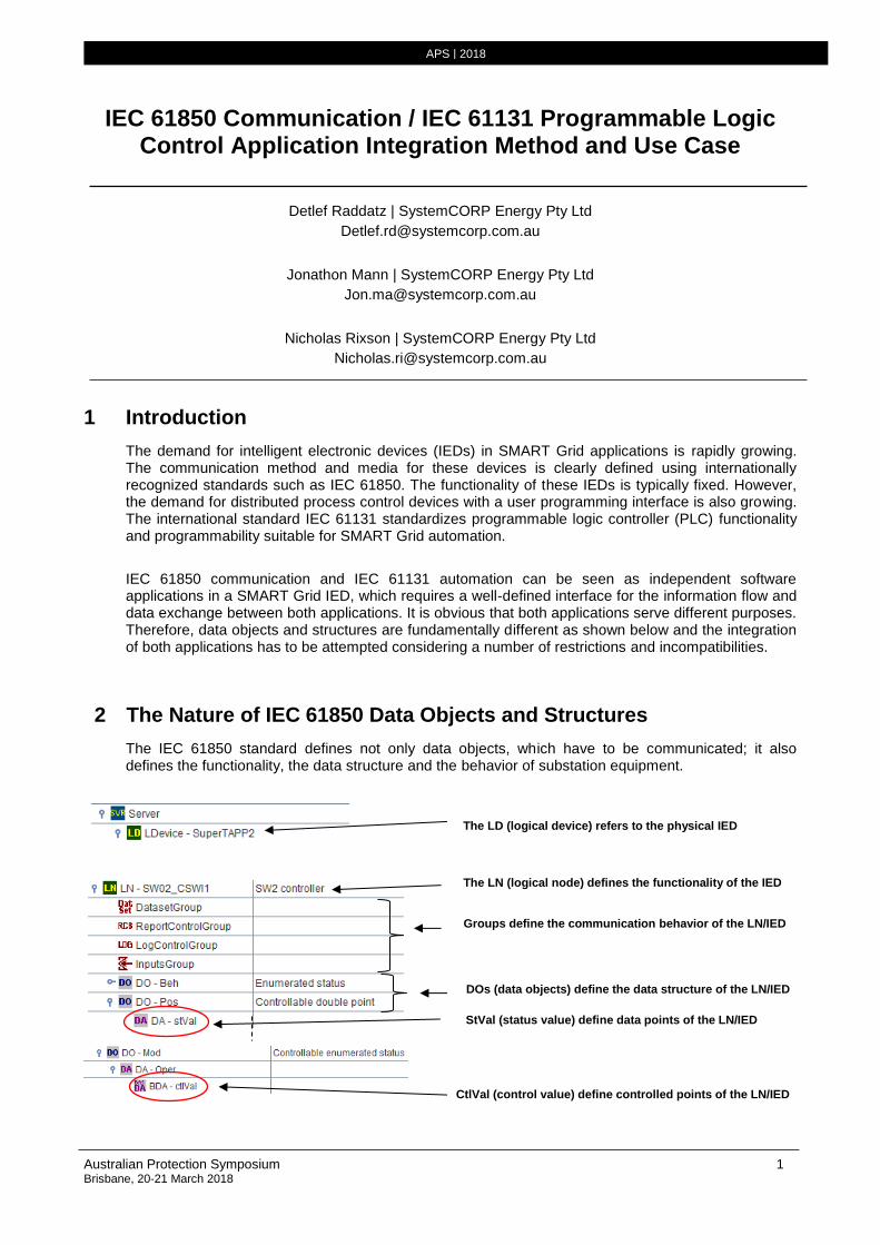
The IEC 61850 standard defines not only data objects, which have to be communicated; it also defines the functionality, the data structure and the behavior of substation equipment.
APS | 2018
The LD (logical device) refers to the physical IED
The LN (logical node) defines the functionality of the IED
Groups define the communication behavior of the LN/IED
DOs (data objects) define the data structure of the LN/IED
StVal (status value) define data points of the LN/IED
CtlVal (control value) define controlled points of the LN/IED
2 Australian Protection Symposium Brisbane, 20-21 March 2018
APS | 2018
stVal and ctlVal are real inputs and outputs of the IED and processed by its firmware for status update and control operations. Data quality, which indicates whether the current data value is valid or invalid and time stamp information is also provided and mandatory for IEC 61850 communication.
Events for data changes are typically created in real time. The correct time stamping of events is treated with very high priority.
3 The Nature of IEC 61131 Data Objects and Structures
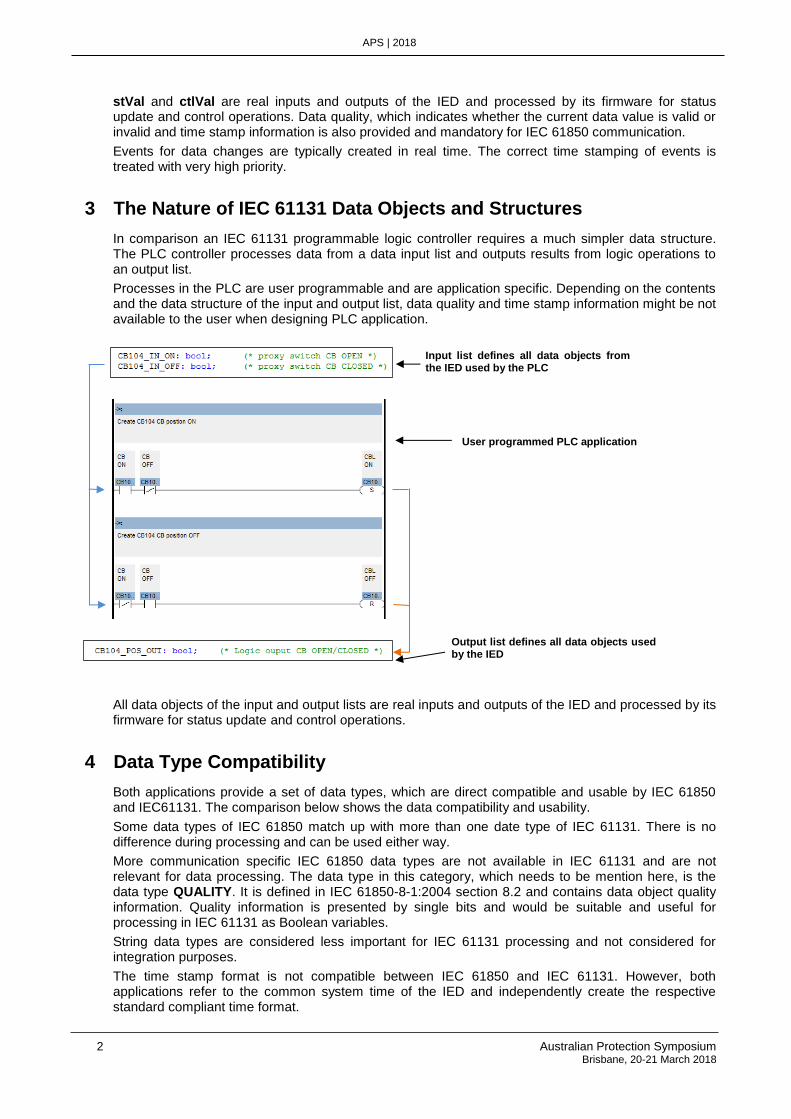
In comparison an IEC 61131 programmable logic controller requires a much simpler data structure. The PLC controller processes data from a data input list and outputs results from logic operations to an output list.
Processes in the PLC are user programmable and are application specific. Depending on the contents and the data structure of the input and output list, data quality and time stamp information might be not available to the user when designing PLC application.
All data objects of the input and output lists are real inputs and outputs of the IED and processed by its firmware for status update and control operations.
4 Data Type Compatibility
Both applications provide a set of data types, which are direct compatible and usable by IEC 61850 and IEC61131. The comparison below shows the data compatibility and usability.
Some data types of IEC 61850 match up with more than one date type of IEC 61131. There is no difference during processing and can be used either way.
More communication specific IEC 61850 data types are not available in IEC 61131 and are not relevant for data processing. The data type in this category, which needs to be mention here, is the data type QUALITY. It is defined in IEC 61850-8-1:2004 section 8.2 and contains data object quality information. Quality information is presented by single bits and would be suitable and useful for processing in IEC 61131 as Boolean variables.
String data types are considered less important for IEC 61131 processing and not considered for integration purposes.
The time stamp format is not compatible between IEC 61850 and IEC 61131. However, both applications refer to the common system time of the IED and independently create the respective standard compliant time format.
Input list defines all data objects from the IED used by the PLC
Output list defines all data objects used by the IED
User programmed PLC application
Australian Protection Symposium 3 Brisbane, 20-21 March 2018
APS | 2018
Item IEC 61850-7-2 Section 5.5.2 Data
Types IEC 61131-3 Data
Types Description Range/Size
1 IEC_DATATYPE_BOOLEAN BOOL Data is type Boolean 0(FALSE, 1(TRUE)
1 or 8 bit size
2 IEC_DATATYPE_INT8 SINT An integer of 8 bits -128 to +127
8 bit size
3 IEC_DATATYPE_INT16 INT An integer of 16 bits -32 768 to +32 767
16 bit size
4 IEC_DATATYPE_INT32 DINT An integer of 32 bits -2.147.483.647 to +2.147.483.647 32 bit size
5 IEC_DATATYPE_8U USINT, BYTE An unsigned integer of 8 bits
0 to 255
8 bit size
6 IEC_DATATYPE_16U UINT, WORD An unsigned integer of 16 bits
0 to 65 535
16 bit size
7 IEC_DATATYPE_32U UDINT, DWORD An unsigned integer of 32 bits
0 to 4.294.967.295
32 bit size
8 IEC_DATATYPE_FLOAT32 REAL A IEEE 754 single precision floating point
+/-3.4E+/-38 32 bit size
9 IEC_DATATYPE_FLOAT64 LREAL A IEEE 754 single double floating point
+/-1.8E+/-308
64 bit size
10 IEC_DATATYPE_ENUM Note 1 Ordered set of values; extended allowed
11 IEC_DATATYPE_CODED_ENUM Note 1 Ordered set of values; not allowed to be extended
12 IEC_DATATYPE_OCTET_STRING Note 1 A string of Octet characters
13 IEC_DATATYPE_VISIBLE_STRING Note 1 A string of Visible characters
14 IEC_DATATYPE_UNICODE_STRING Note 1 A string of Unicode characters
15 IEC_DATATYPE_TIMESTAMP DATE_AND_TIME Time Stamp type (IEC 61850-7-2:2003 section 5.5.3.7.1)
Absolute Time Format
16 IEC_DATATYPE_QUALITY Note 2 Quality Data Type
Note 1: Not considered Note 2: Special data conversion required for integration using the system time of the IED
5 Linking IEC 61850 Data Objects with IEC 61131 Process Data Objects
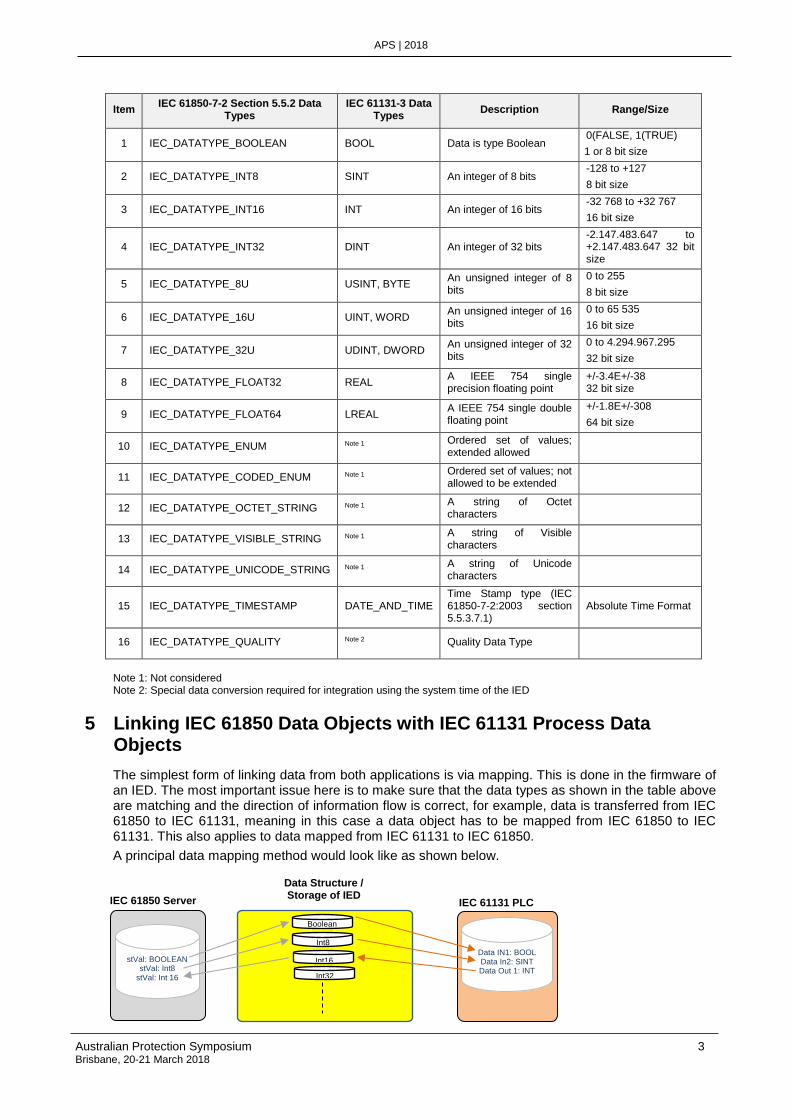
The simplest form of linking data from both applications is via mapping. This is done in the firmware of an IED. The most important issue here is to make sure that the data types as shown in the table above are matching and the direction of information flow is correct, for example, data is transferred from IEC 61850 to IEC 61131, meaning in this case a data object has to be mapped from IEC 61850 to IEC 61131. This also applies to data mapped from IEC 61131 to IEC 61850.
A principal data mapping method would look like as shown below.
Boolean
Int8
Int16
Int32
stVal: BOOLEAN stVal: Int8
stVal: Int 16 . .
IEC 61850 Server
Data Structure / Storage of IED
IEC 61131 PLC
Data IN1: BOOL Data In2: SINT Data Out 1: INT
.
.
4 Australian Protection Symposium Brisbane, 20-21 March 2018
APS | 2018
The firmware of the IED matches data types as per the data type table in this document in the IED database system. The configuration tool of the IED populates the data tables of the system database and the information of data object mapping between IEC 61850 and IEC 61131. Each data change event is reported to the system database system and then forwarded to the receiving application as per mapping information.
During the mapping process the configuration tool also automatically adds and auto-creates additional data objects, which are required for linking IEC 61850 and IEC 61131.
• Each data object owned by the IEC 61131 application has an auto-generated QUALIFIER added
• Each mapped control command has a number of additional data objects added
The additional data objects for control commands are discussed later in this document.
5.1 Processing of IEC 61850 Quality Flags
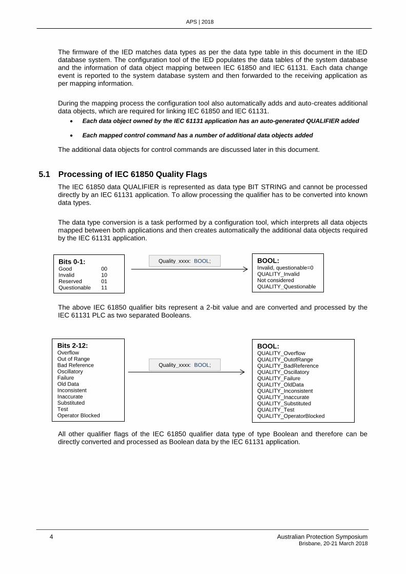
The IEC 61850 data QUALIFIER is represented as data type BIT STRING and cannot be processed directly by an IEC 61131 application. To allow processing the qualifier has to be converted into known data types.
The data type conversion is a task performed by a configuration tool, which interprets all data objects mapped between both applications and then creates automatically the additional data objects required by the IEC 61131 application.
The above IEC 61850 qualifier bits represent a 2-bit value and are converted and processed by the IEC 61131 PLC as two separated Booleans.
All other qualifier flags of the IEC 61850 qualifier data type of type Boolean and therefore can be directly converted and processed as Boolean data by the IEC 61131 application.
Bits 0-1: Good 00 Invalid 10 Reserved 01 Questionable 11
BOOL: Invalid, questionable=0 QUALITY_Invalid Not considered QUALITY_Questionable
Quality_xxxx: BOOL;
Bits 2-12: Overflow Out of Range Bad Reference Oscillatory Failure Old Data Inconsistent Inaccurate Substituted Test Operator Blocked
Quality_xxxx: BOOL;
BOOL: QUALITY_Overflow QUALITY_OutofRange QUALITY_BadReference QUALITY_Oscillatory QUALITY_Failure QUALITY_OldData QUALITY_Inconsistent QUALITY_Inaccurate QUALITY_Substituted QUALITY_Test QUALITY_OperatorBlocked
Australian Protection Symposium 5 Brisbane, 20-21 March 2018
APS | 2018
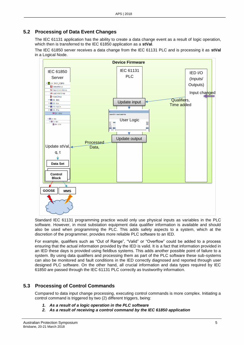
5.2 Processing of Data Event Changes
The IEC 61131 application has the ability to create a data change event as a result of logic operation, which then is transferred to the IEC 61850 application as a stVal.
The IEC 61850 server receives a data change from the IEC 61131 PLC and is processing it as stVal in a Logical Node.
Standard IEC 61131 programming practice would only use physical inputs as variables in the PLC software. However, in most substation equipment data qualifier information is available and should also be used when programming the PLC. This adds safety aspects to a system, which at the discretion of the programmer, provides more reliable PLC software to an IED.
For example, qualifiers such as “Out of Range”, “Valid” or “Overflow” could be added to a process ensuring that the actual information provided by the IED is valid. It is a fact that information provided in an IED these days is provided using fieldbus systems. This adds another possible point of failure to a system. By using data qualifiers and processing them as part of the PLC software these sub-systems can also be monitored and fault conditions in the IED correctly diagnosed and reported through user designed PLC software. On the other hand, all crucial information and data types required by IEC 61850 are passed through the IEC 61131 PLC correctly as trustworthy information.
5.3 Processing of Control Commands
Compared to data input change processing, executing control commands is more complex. Initiating a control command is triggered by two (2) different triggers, being:
1. As a result of a logic operation in the PLC software 2. As a result of receiving a control command by the IEC 61850 application
IEC 61850
Server
IEC 61131
PLC IED I/O
(Inputs/
Outputs)
Input changed
Update stVal,
q, t
Data Set
Control Block Control
Block
GOOSE MMS
Device Firmware
Processed Data,
Qualifiers, time
User Logic
Update input list
Qualifiers, Time added
Update output list
6 Australian Protection Symposium Brisbane, 20-21 March 2018
APS | 2018
When trigger option 1) occurs the PLC itself is the commanding application and controls the entire process with the commanded application.
Trigger option 2) requires additional communication options between IEC 61850 and IEC 61131 since the PLC is not the commanding application. In this case the PLC is “added” into the command chain while the control command is communicated to the commanded application.
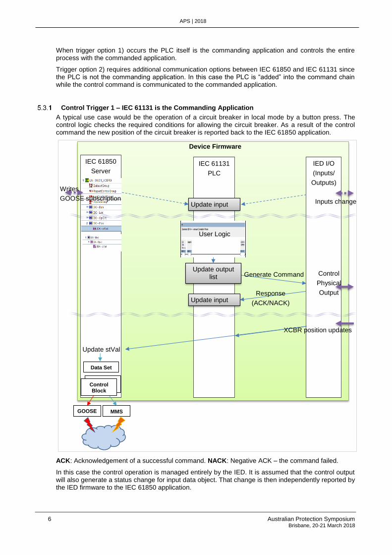
Control Trigger 1 – IEC 61131 is the Commanding Application
A typical use case would be the operation of a circuit breaker in local mode by a button press. The control logic checks the required conditions for allowing the circuit breaker. As a result of the control command the new position of the circuit breaker is reported back to the IEC 61850 application.
ACK: Acknowledgement of a successful command. NACK: Negative ACK – the command failed.
In this case the control operation is managed entirely by the IED. It is assumed that the control output will also generate a status change for input data object. That change is then independently reported by the IED firmware to the IEC 61850 application.
IEC 61850
Server IEC 61131
PLC
IED I/O
(Inputs/
Outputs)
Inputs change
User Logic
XCBR position updates
Update stVal
Data Set
Control Block Control
Block
GOOSE MMS
Device Firmware
Writes
GOOSE subscription
Update output list
CmdTrigger
Update input list
Generate Command Control
Physical
Output Update input list
Response
(ACK/NACK)
Australian Protection Symposium 7 Brisbane, 20-21 March 2018
APS | 2018
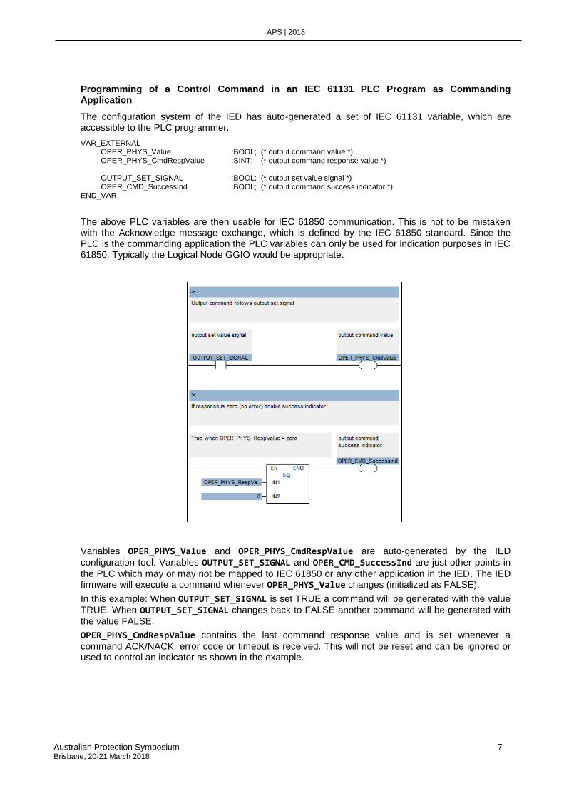
Programming of a Control Command in an IEC 61131 PLC Program as Commanding Application
The configuration system of the IED has auto-generated a set of IEC 61131 variable, which are accessible to the PLC programmer.
VAR_EXTERNAL OPER_PHYS_Value :BOOL; (* output command value *) OPER_PHYS_CmdRespValue :SINT; (* output command response value *) OUTPUT_SET_SIGNAL :BOOL; (* output set value signal *) OPER_CMD_SuccessInd :BOOL; (* output command success indicator *) END_VAR
The above PLC variables are then usable for IEC 61850 communication. This is not to be mistaken with the Acknowledge message exchange, which is defined by the IEC 61850 standard. Since the PLC is the commanding application the PLC variables can only be used for indication purposes in IEC 61850. Typically the Logical Node GGIO would be appropriate.
Variables OPER_PHYS_Value and OPER_PHYS_CmdRespValue are auto-generated by the IED
configuration tool. Variables OUTPUT_SET_SIGNAL and OPER_CMD_SuccessInd are just other points in
the PLC which may or may not be mapped to IEC 61850 or any other application in the IED. The IED firmware will execute a command whenever OPER_PHYS_Value changes (initialized as FALSE).
In this example: When OUTPUT_SET_SIGNAL is set TRUE a command will be generated with the value
TRUE. When OUTPUT_SET_SIGNAL changes back to FALSE another command will be generated with
the value FALSE.
OPER_PHYS_CmdRespValue contains the last command response value and is set whenever a
command ACK/NACK, error code or timeout is received. This will not be reset and can be ignored or used to control an indicator as shown in the example.
8 Australian Protection Symposium Brisbane, 20-21 March 2018
APS | 2018
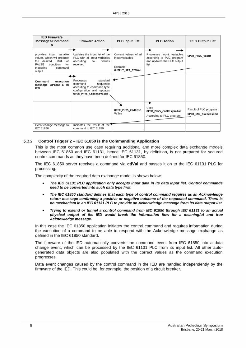
IED Firmware Messages/Command
s Firmware Action PLC Input List PLC Action PLC Output List
provides input variable values, which will produce the desired TRUE or FALSE condition for triggering command output
Updates the input list of the PLC with all input variables according to values received
Current values of all input variables
Example: OUTPUT_SET_SIGNAL
Processes input variables according to PLC program and updates the PLC output list
OPER_PHYS_Value
Command execution message OPERATE in IED
Processes standard command sequence according to command type configuration and updates OPER_PHYS_CmdRespValue
OPER_PHYS_CmdRespValue
Uses OPER_PHYS_CmdRespValue
According to PLC program
Result of PLC program
OPER_CMD_SuccessInd
Event change message to IEC 61850
Indicates the result of the command to IEC 61850
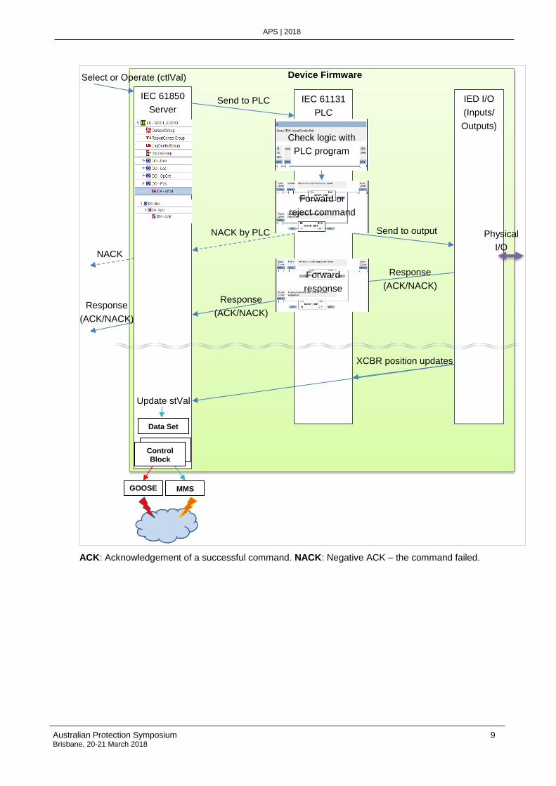
Control Trigger 2 – IEC 61850 is the Commanding Application
This is the most common use case requiring additional and more complex data exchange models between IEC 61850 and IEC 61131, hence IEC 61131, by definition, is not prepared for secured control commands as they have been defined for IEC 61850.
The IEC 61850 server receives a command via ctlVal and passes it on to the IEC 61131 PLC for processing.
The complexity of the required data exchange model is shown below:
• The IEC 61131 PLC application only accepts input data in its data input list. Control commands need to be converted into such data type first.
• The IEC 61850 standard defines that each type of control command requires as an Acknowledge return message confirming a positive or negative outcome of the requested command. There is no mechanism in an IEC 61131 PLC to provide an Acknowledge message from its data output list.
• Trying to extend or tunnel a control command from IEC 61850 through IEC 61131 to an actual physical output of the IED would break the information flow for a meaningful and true Acknowledge message.
In this case the IEC 61850 application initiates the control command and requires information during the execution of a command to be able to respond with the Acknowledge message exchange as defined in the IEC 61850 standard.
The firmware of the IED automatically converts the command event from IEC 61850 into a data change event, which can be processed by the IEC 61131 PLC from its input list. All other auto-generated data objects are also populated with the correct values as the command execution progresses.
Data event changes caused by the control command in the IED are handled independently by the firmware of the IED. This could be, for example, the position of a circuit breaker.
Australian Protection Symposium 9 Brisbane, 20-21 March 2018
APS | 2018
ACK: Acknowledgement of a successful command. NACK: Negative ACK – the command failed.
IEC 61850
Server
Select or Operate (ctlVal)
IEC 61131
PLC
IED I/O
(Inputs/
Outputs)
Send to PLC
Send to output
Check logic with
PLC program
Response
(ACK/NACK)
XCBR position updates
Update stVal
Data Set
Control Block Control
Block
GOOSE MMS
Device Firmware
Physical
I/O
Forward or
reject command
NACK by PLC
NACK
Forward
response Response
(ACK/NACK) Response
(ACK/NACK)
10 Australian Protection Symposium Brisbane, 20-21 March 2018
APS | 2018
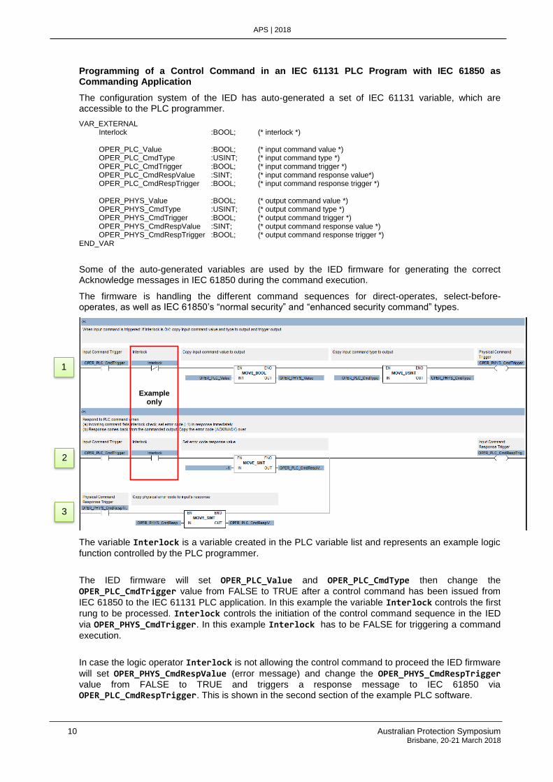
Programming of a Control Command in an IEC 61131 PLC Program with IEC 61850 as Commanding Application
The configuration system of the IED has auto-generated a set of IEC 61131 variable, which are accessible to the PLC programmer.
VAR_EXTERNAL Interlock :BOOL; (* interlock *) OPER_PLC_Value :BOOL; (* input command value *) OPER_PLC_CmdType :USINT; (* input command type *) OPER_PLC_CmdTrigger :BOOL; (* input command trigger *) OPER_PLC_CmdRespValue :SINT; (* input command response value*) OPER_PLC_CmdRespTrigger :BOOL; (* input command response trigger *) OPER_PHYS_Value :BOOL; (* output command value *) OPER_PHYS_CmdType :USINT; (* output command type *) OPER_PHYS_CmdTrigger :BOOL; (* output command trigger *) OPER_PHYS_CmdRespValue :SINT; (* output command response value *) OPER_PHYS_CmdRespTrigger :BOOL; (* output command response trigger *) END_VAR
Some of the auto-generated variables are used by the IED firmware for generating the correct Acknowledge messages in IEC 61850 during the command execution.
The firmware is handling the different command sequences for direct-operates, select-before-operates, as well as IEC 61850’s “normal security” and “enhanced security command” types.
The variable Interlock is a variable created in the PLC variable list and represents an example logic
function controlled by the PLC programmer.
The IED firmware will set OPER_PLC_Value and OPER_PLC_CmdType then change the
OPER_PLC_CmdTrigger value from FALSE to TRUE after a control command has been issued from
IEC 61850 to the IEC 61131 PLC application. In this example the variable Interlock controls the first
rung to be processed. Interlock controls the initiation of the control command sequence in the IED
via OPER_PHYS_CmdTrigger. In this example Interlock has to be FALSE for triggering a command
execution.
In case the logic operator Interlock is not allowing the control command to proceed the IED firmware
will set OPER_PHYS_CmdRespValue (error message) and change the OPER_PHYS_CmdRespTrigger value from FALSE to TRUE and triggers a response message to IEC 61850 via OPER_PLC_CmdRespTrigger. This is shown in the second section of the example PLC software.
Example only
1
2
3
Australian Protection Symposium 11 Brisbane, 20-21 March 2018
APS | 2018
The IED firmware will execute a command using OPER_PHYS_Value and OPER_PHYS_CmdType when
the OPER_PHYS_CmdTrigger value is changed by the IEC 61131 PLC from FALSE to TRUE.
The IED firmware will generate a command response to IEC 61850 using OPER_PLC_CmdRespValue when the OPER_PLC_CmdRespTrigger value is changed by the IEC 61131 PLC from FALSE to TRUE.
Due to the complexity of the command processing here some more explanations from a different angle.
In section 1: (when the interlock allows the execution of a command) The OPER_PLC_CmdTrigger enables the IED firmware to copy the OPER_PLC_Value to OPER_PHYS_Value and OPER_PLC_CmdType to OPER_PHYS_CmdType. The OPER_PHYS_CmdTrigger changes from FALSE to TRUE signaling to the
IED firmware to execute a command with the copied values.
In section 2: (when the interlock prevents the command) The OPER_PLC_CmdTrigger enables the
copy of -1 (an error code) to OPER_PLC_CmdRespValue. The OPER_PLC_CmdRespTrigger changes
from FALSE to TRUE signaling to the IED firmware that a responses is to be generated to IEC 61850 with the copied error code – this time it is a negative Acknowledgement.
In section 3: (when the executed command has completed) The OPER_PHYS_CmdRespTrigger enables the copy of OPER_PHYS_CmdRespValue to OPER_PLC_CmdRespValue. The
OPER_PLC_CmdRespTrigger changes from FALSE to TRUE signaling the IED firmware that a
response is to be generated to IEC 61850 with the copied value – this time the Acknowledgement matches the response given by the physical output.
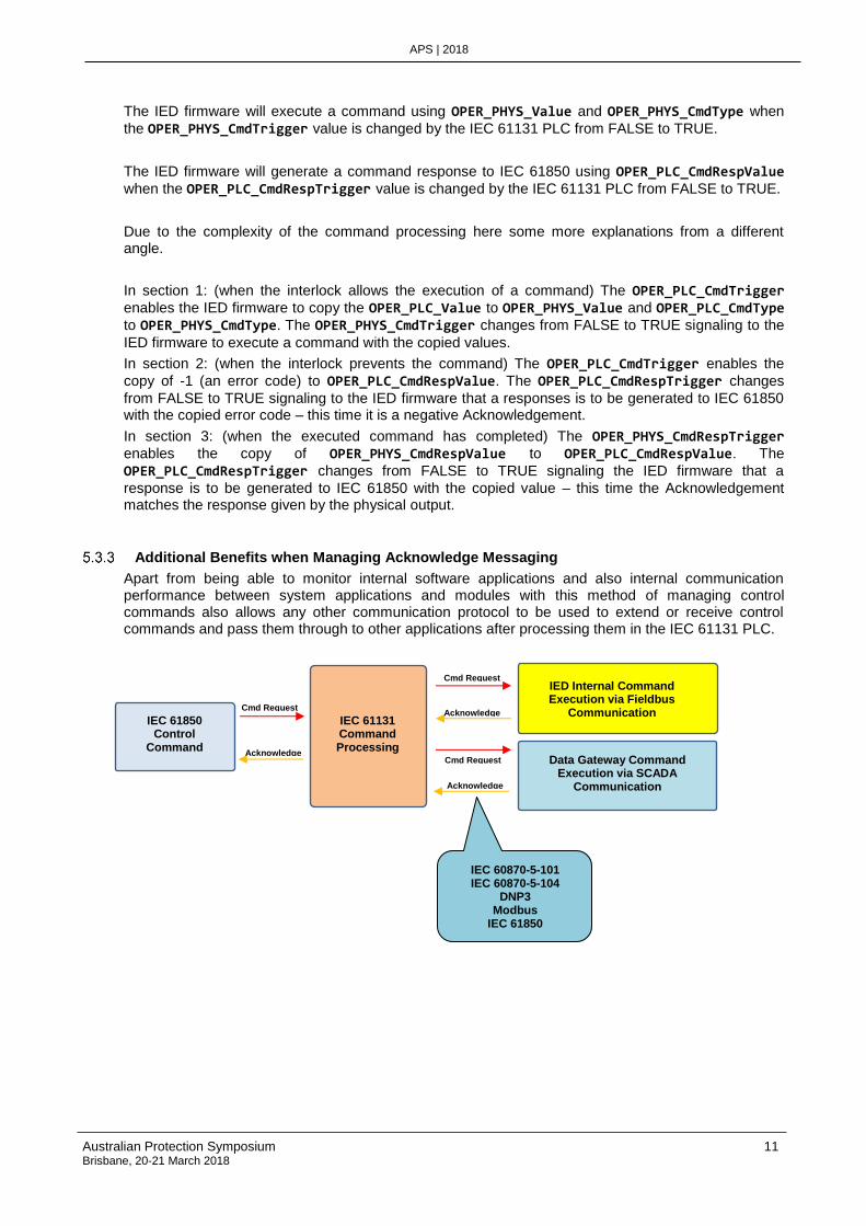
Additional Benefits when Managing Acknowledge Messaging
Apart from being able to monitor internal software applications and also internal communication performance between system applications and modules with this method of managing control commands also allows any other communication protocol to be used to extend or receive control commands and pass them through to other applications after processing them in the IEC 61131 PLC.
IEC 61850 Control
Command
IEC 61131 Command Processing
IED Internal Command Execution via Fieldbus
Communication
Data Gateway Command Execution via SCADA
Communication
Cmd Request
Cmd Request
Cmd Request Acknowledge
Acknowledge
Acknowledge
IEC 60870-5-101 IEC 60870-5-104
DNP3 Modbus
IEC 61850
12 Australian Protection Symposium Brisbane, 20-21 March 2018
APS | 2018
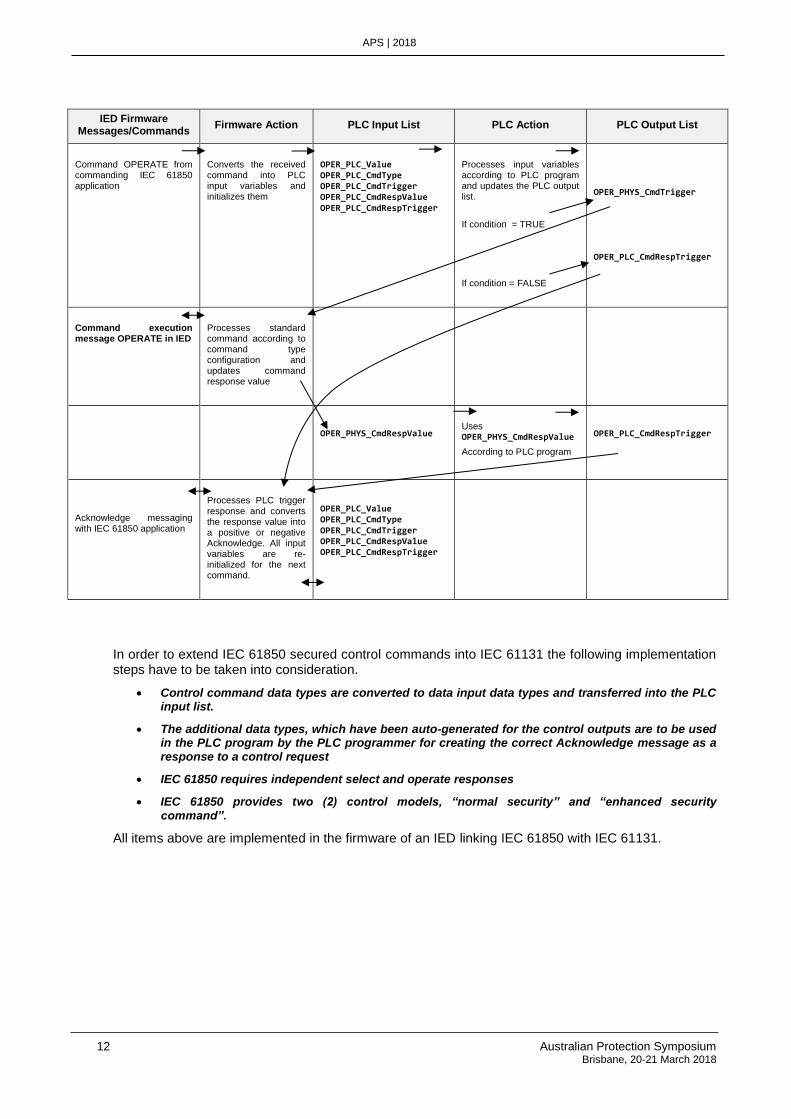
IED Firmware Messages/Commands
Firmware Action PLC Input List PLC Action PLC Output List
Command OPERATE from commanding IEC 61850 application
Converts the received command into PLC input variables and initializes them
OPER_PLC_Value OPER_PLC_CmdType OPER_PLC_CmdTrigger OPER_PLC_CmdRespValue OPER_PLC_CmdRespTrigger
Processes input variables according to PLC program and updates the PLC output list.
If condition = TRUE
If condition = FALSE
OPER_PHYS_CmdTrigger
OPER_PLC_CmdRespTrigger
Command execution message OPERATE in IED
Processes standard command according to command type configuration and updates command response value
OPER_PHYS_CmdRespValue
Uses OPER_PHYS_CmdRespValue
According to PLC program
OPER_PLC_CmdRespTrigger
Acknowledge messaging with IEC 61850 application
Processes PLC trigger response and converts the response value into a positive or negative Acknowledge. All input variables are re-initialized for the next command.
OPER_PLC_Value OPER_PLC_CmdType OPER_PLC_CmdTrigger OPER_PLC_CmdRespValue OPER_PLC_CmdRespTrigger
In order to extend IEC 61850 secured control commands into IEC 61131 the following implementation steps have to be taken into consideration.
• Control command data types are converted to data input data types and transferred into the PLC input list.
• The additional data types, which have been auto-generated for the control outputs are to be used in the PLC program by the PLC programmer for creating the correct Acknowledge message as a response to a control request
• IEC 61850 requires independent select and operate responses
• IEC 61850 provides two (2) control models, “normal security” and “enhanced security command”.
All items above are implemented in the firmware of an IED linking IEC 61850 with IEC 61131.
Australian Protection Symposium 13 Brisbane, 20-21 March 2018
APS | 2018
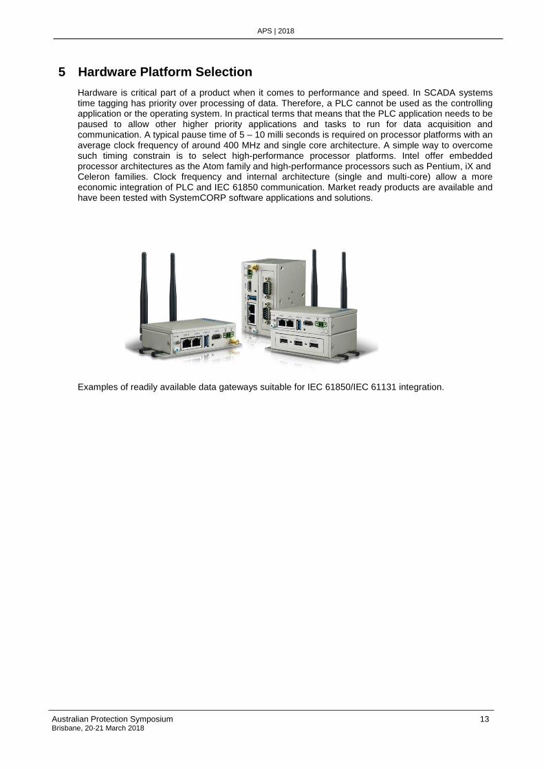
5 Hardware Platform Selection
Hardware is critical part of a product when it comes to performance and speed. In SCADA systems time tagging has priority over processing of data. Therefore, a PLC cannot be used as the controlling application or the operating system. In practical terms that means that the PLC application needs to be paused to allow other higher priority applications and tasks to run for data acquisition and communication. A typical pause time of 5 – 10 milli seconds is required on processor platforms with an average clock frequency of around 400 MHz and single core architecture. A simple way to overcome such timing constrain is to select high-performance processor platforms. Intel offer embedded processor architectures as the Atom family and high-performance processors such as Pentium, iX and Celeron families. Clock frequency and internal architecture (single and multi-core) allow a more economic integration of PLC and IEC 61850 communication. Market ready products are available and have been tested with SystemCORP software applications and solutions. Examples of readily available data gateways suitable for IEC 61850/IEC 61131 integration.
14 Australian Protection Symposium Brisbane, 20-21 March 2018
APS | 2018
6 Conclusion
Integrating IEC 61850 into an IED is not trivial. Adding an IEC 61131 programmable logic controller to the IED turns an integration project into a highly complex undertaking. Detailed knowledge is required what IEC 61850 represents as the communication part of the device. This part is definitely reserved for engineers with expertise in the field of data communication.
On the other hand, a programmable logic controller conforming to the standard IEC 61131 is the domain of process automation engineers.
By experience a combined skill set is hard to find between those two engineering disciplines. The nature of both applications, IEC 61850 and IEC 61131, need to be understood beyond of using them as an application engineer. Only then it will be possible to integrate both application in one device in a manner, which allows the user – IEC 61131 programmer and IEC 61850 configurator - utilizing all features offered from both worlds, data communication and process automation.
The integration should give the user options to:-
• Provide data change events for IEC 61850 in real-time independent from any IEC 61131 operation.
• Process any data in the device using the IEC 61131 application independent from IEC 61850 communication.
• Prevent any data incompatibility between IEC 61850 and IEC 61131 when linking and mapping data objects between both applications. Data compatibility has to be maintained at all times.
• Maintain precise time stamp information for IEC 61850 data objects
• Provide fast IEC 61131 data processing for the correct functionality of the device
• Allow the usage of data objects and data qualifiers with its status flags in the IEC 61131 application and the programmer of this application adding more security to the PLC software
• Assure that the secure control command sequences of IEC 61850 are also utilized in an IEC 61131 user program. This makes sure that the high standards of secured controls are extended into the IEC 61131 PLC software.
After years of experience it is also emphasis on one the following issue – make sure the processor and hardware platform selected supports all requirements of an IED. This has not been discussed in this document. However, by experience these are important issue for a successful integration:
• Long-time availability of the processor platform needs to be guaranteed
• Electronic component obsolescence management has to be in place
• Software operating systems must be real-time capable
• Independent certification process for IEC 61850 and IEC 61131 is highly recommended
• Work with experts in this field for the integration – it will save money and time after all!
Once the integration of IEC 61131 and IEC 61850 has been successfully completed, a product will be extremely versatile for communication tasks and fully compliant with communication standards, which are these days mandatory in the electrical utility industry in most regions of the world. The IEC 61131 application transforms the product into a true process automation device, which is user friendly to program and easily re-programmed if requirements change.
Australian Protection Symposium 15 Brisbane, 20-21 March 2018
APS | 2018
About the Authors
Detlef Raddatz received his engineering degree from the Technical University in Heilbronn, Germany. He has more than 28 years of experience in in SCADA, data communication and process technology for the electrical utility industry. With comprehensive knowledge of embedded hardware and software design he is responsible for a number of substation hardened product designs deployed worldwide such as advanced IEC 61850 communication gateways with automation capabilities. He is member of the UCA and DNP3 user groups and has authored and presented a number of technical papers at international conferences. He is Managing Director of SystemCORP Energy, Australia.
Jonathon Mann received his Bachelor of Science (Information Technology) from Curtin University in Perth, Western Australia in 2011. After working at Curtin University tutoring networking and engineering units Jonathon joined SystemCorp and has spent the last 5 years in the communications field specializing in IEC61850. Jonathon is the senior software engineer managing and maintaining SystemCORP’s cross platform IEC61850 stack.
Nicholas Rixson studied at the University of Western Australia, attaining degrees in Electrical and Electronic Engineering (hons) and Computer and Mathematical Science. He has been working in the electrical utility are since university, first at the state’s power utility in the analytics division, then moving on to writing embedded platform communication and automation at SystemCORP Energy.