“i hereby declare that this ... -...
TRANSCRIPT


“I hereby declare that this project is written by me and it is my own effort and that no
part has been plagiarised without citations.”
Signature : ………………………………..
Name of Writer : Samawi bin Ismail
Date : 27 March 2008
ii
ii

To my beloved mother and father
And my family
iii

ACKNOWLEDGEMENT
I wish to acknowledge a valuable advice and supports to my supervisor, En.
Ahmad Anas bin Yusof for guiding and educating me along the path of conducting
my Projek Sarjana Muda.
It is equally important to express an appreciation to all lecturers who either
involved directly or indirectly in implementing my project by giving me supports,
references, guidance and direction so that the project flows smoothly.
Moreover, I wish to say my deepest thanks to my family, colleagues and
others who never stop assisting me by bestowing a lot of orientations in order to
complete my project.
iv

ABSTRACT
Fluid power plays a crucial task in today’s industry as this meadow deals with
the generation, control and transmission of pressurised fluids. The development of a
portable pneumatic jacking system is one portion of fluid power which applies air as
a fluid medium and used for lifting the load around 1000 kg. The main objective of
this project is to develop and produce a device which can help people to utilise it as a
cylinder of jacking system. The investigation has been conducted by taking the
advantages of air compared to liquid which clearly defined that air is light and not
messy. Other than that, the studies have also been done by applying the relationships
between the force imposed to the cylinder, the working pressure of compressed air
and the size of the tube. The project done was based on several methodologies which
were the design concept, materials used, assembling processes, bill of materials and
last but not least the analysis and calculation. After the completion of producing the
product, some field tests have been conducted which were on the human weigh, on
the pneumatic table and on the Kancil car; the maximum operating pressure of
3.4474 bars could be used to lift the weigh of 255.9156 kg with no stroke measured.
By comparing the analyses made with the results obtained, it is clearly seen that the
use of 3.4474 bars pressure could only be used to lift the weigh below than 255.9156
kg. Therefore, the tyres are not to be recommended to lift the weigh of car, otherwise
the use of specialised material such as air lifting bag is suggested since the bag has
been specialised for the use of high pressure.
v
v

ABSTRAK
Kuasa bendalir memainkan peranan yang besar dalam bidang industri dewasa
ini kerana bidang ini melibatkan kuasa penjanaan, kawalan dan penghantaran yang
mengaplikasikan bendalir bertekanan. Pembangunan sistem jek udara mudah alih
adalah satu cabang dalam bidang kuasa bendalir yang menggunakan udara sebagai
bendalir dan digunakan untuk tujuan mengangkat beban kira-kira 1000 kg. Objektif
utama projek ini adalah untuk membangun dan menghasilkan satu alat yang mana
boleh menolong para penguna untuk menggunakannya sebagai satu silinder bagi
sistem jek. Penelitian telah pun dilakukan dengan mengambilkira kelebihan udara
berbanding cecair yang mana secara jelasnya udara adalah ringan dan tidak
mengotorkan. Selain daripada itu, kajian juga telah pun dijalankan dengan
mengaplikasikan hubungan antara daya yang dikenakan ke atas silinder, tekanan
bekerja udara termampat dan saiz tiub. Projek yang telah dilaksanakan ini adalah
berdasarkan kepada beberapa kaedah seperti konsep rekabentuk, bahan-bahan yang
digunakan, proses-proses penyambungan, bil bahan-bahan; menekankan jumlah kos
keseluruhan bagi pelaksanaan projek dan akhir sekali analisis dan pengiraan. Setelah
menyiapkan produk, beberapa ujikaji telah dilakukan seperti ujikaji ke atas berat
manusia, ujikaji ke atas meja pneumatik dan ujikaji ke atas kereta Kancil. Dengan
membandingkan analisis-analisis yang dibuat dengan keputusan yang didapati, ianya
dapat dilihat secara jelas bahawa penggunaan tekanan sebanyak 3.4474 bar hanya
dapat mengangkat beban di bawah 255.9156 kg. Dengan ini, penggunaan tayar
sebagai elemen untuk mengangkat beban tidak disarankan tetapi digantikan dengan
penggunaan bahan yang telah dikhaskan seperti air lifting bag kerana beg ini mampu
beroperasi dengan tekanan yang tinggi.
vi
CONTENTS
CHAPTER CONTENT PAGE
PENGAKUAN ii
DEDICATION iii
ACKNWLODGEMENT iv
ABSTRACT v
ABSTRAK vi
CONTENTS ix-xi
LIST OF TABLES xii
LIST OF FIGURES xiii-xiv
LIST OF SYMBOLS xv
LIST OF APPENDICES xvi
CHAPTER 1 INTRODUCTION 1
1.1 BACKGROUND 1-2
1.2 PROBLEM STATEMENT 2-3
1.3 OBJECTIVES OF PROJECT 3
1.4 SCOPES OF PROJECT 3
1.5 EXPECTED OUTCOMES 4
1.6 FLOWCHART OF PSM 1 & 2
IMPLEMENTATION 5
CHAPTER 2 LITERATURE REVIEW 6
2.1 INTRODUCTION 6
ix
ix
2.2 FLUID POWER 7
2.3 RELATIONSHIPS BETWEEN RESSURE,
DIAMETER AND FORCE 8
2.4 JACKS IN MARKET 9
2.4.1 MECHANICAL JACKS 9-11
2.4.2 HYDRAULIC JACKS 12-14
2.4.3 AIR TO HYDRAULIC JACKS 14
2.4.4 AIR LIFTING BAGS 15
2.5 PREVIOUS INVENTED PNEUMATIC AND
HYDRAULIC JACKS 16
2.5.1 PNEUMATIC JACKS 16-17
2.5.2 PNEUMATIC VEHICLE JACKING SYSTEM 17
2.5.3 ELECTRIC HYDRAULIC JACK/AIR PUMP 18
CHAPTER 3 METHODOLOGY – ANALYSIS AND CALCULATION 19
3.1 INTRODUCTION 19
3.2 DESIGN CONCEPT 19-20
3.3 MATERIAL USED 21
3.3.1 TYRE 21
3.3.2 PRESSURE REGULATOR 22
3.3.3 GATE VALVE 23
3.3.4 STRAIGHT CONNECTOR 24
3.3.5 FITTER 25
3.3.6 CLIPPER (HEAD) 26
3.3.7 CLIPPER (RING) 27
3.3.8 8-mm TUBE 28
3.3.9 6-mm TUBE 29
3.3.10 COVER 30
3.4 ASSEMBLING PROCESSES 30-35
3.5 BILL OF MATERIALS 36
3.6 ANALYSIS AND CALCULATION 37
3.6.1 ANALYSIS OF THE CAPABILITY OF THE
PNEUMATIC JACKING SYSTEM IN
x

LIFTING AN OBJECT 37-39
3.6.2 ANALYSIS OF THE WEIGH BY USING THE
SAFETY FACTOR OF 3.0 39-40
3.6.3 ANALYSIS OF THE CAR’S WEIGHS 40-42
CHAPTER 4 METHODOLOGY – FIELD TEST 43
4.1 INTRODUCTION 43
4.2 FIELD TEST – HUMAN WEIGH 43-45
4.3 FIELD TEST – PNEUMATIC TABLE 45-47
4.4 FIELD TEST – KANCIL CAR 47-48
4.5 DISCUSSION 48-49
CHAPTER 5 CONCLUSION AND RECOMMENDATION 50
5.1 CONCLUSION 50-51
5.2 RECOMMENDATION 51
REFERENCES 52-53
BIBLIOGRAPHY 54-55
APPENDIX 56-66
xi

LIST OF TABLE
NO. TITLE PAGE
1.1 Flowchart of PSM 1 and 2 Implementation 5
3.1 Bill of Materials 36
3.2 Weigh of Malaysia’s Mini Cars 41
xii
LIST OF FIGURE
NO. TITLE PAGE
2.1 Pascal’s principle 7
2.2 Hatchet jacks 10
2.3 Screw jacks 11
2.4 Reel jacks 11
2.5 Hydraulic floor jacks 12
2.6 Hydraulic car jacks 13
2.7 Hydraulic bottle jacks 14
2.8 Air to hydraulic jacks 14
2.9 Air lifting bags 15
2.10 Pneumatic jack 16
2.11 Pneumatic vehicle jacking system 17
2.12 A perspective view of an electric hydraulic jack/air pump 18
3.1 Tyre 21
3.2 Pressure regulator 22
3.3 Gate valve 23
3.4 Straight connector 24
3.5 Fitter 25
3.6 Clipper (head) 26
3.7 Clipper (ring) 27
3.8 8-mm tube 28
3.9 6-mm tube 29
3.10 Cover 30
3.11 Assembling of tyre and clipper 31
3.12 Assembling of the 8-mm tube and clipper 31
xiii

3.13 Assembling of clipper ring and 8-mm tube 32
3.14 Assembling of fitter and 8-mm tube 32
3.15 Assembling of 6-mm tube and fitter 33
3.16 Assembling of pressure gauge, pressure regulator and gate valve 33
3.17 Assembling of pressure regulator and 6-mm tube 34
3.18 Assembling of second tyre and the first tyre 34
3.19 Assembling of cover and second tyre 35
xiv

LIST OF SYMBOLS
F = Force, N
P = Pressure, bar
do = Outer diameter, m
di = Inner diameter, m
= Transcendental and irrational constant = 3.14159
W = Weigh, kg
FS = Factor of safety
g = Gravitational acceleration = 9.81 m/s2
V = Volume, m3
A = Cross sectional area, m2
S = Stroke, m
xv
LIST OF APPENDICES
NO TITLE PAGE
A Tyre 56
Pressure regulator 57
Gate valve 58
Straight connector 59
Fitter 60
Clipper head 61
Clipper ring 62
8-mm tube 63
6-mm tube 64
Cover 65
Pneumatic jacking system 66
xvi

1
CHAPTER 1
INTRODUCTION
The development of portable pneumatic jacking system which is connected to
an air compressor was personally proposed by the author as to possibly assist people
in lifting object whose weighs around 1000 kg. The project was emphasised on the
design, fabrication and the assembling processes of the pneumatic jacking system so
that the proposed project could be utilised as expected. Also, the project was stressed
on the aptitude of the proposed system with the recent systems.
The preparations taken by the author were based on the previous project,
journals, research, readings and other exercises. This report is prepared by describing
detail information and methodology suggested by the author as to clearly inform
readers what the project is all about and how the project has been executed. At the
second end of the report, the author has come up with the analyses as these compare
the theoretical lesson investigated by the author with the practical results. Plus, the
author has made a conclusion and a recommendation of the proposed project.
1.1 BACKGROUND
A portable pneumatic jacking system is a device used to assist users to lift
object whose weighs around 1000 kg. It consists of two tyres, one pressure regulator,
one gate valve, two straight connectors, one fitter, 8-mm tube, 6-mm tube and two
2
clippers. All of these materials are available in the market and they are easy to be
obtained.
This device can be used to lift weigh which is not practically to be
recommended for heavy load since the application of pneumatic jacking system
utilises small pressure inside the jack and small area of the tube. However, the use of
this jacking system surely functions and yet can be used to lift load.
People can easily use this jack by connecting the hose of air compressor to
the pneumatic jacking system via a straight connector. Once the compressor has
established its power, the compressor will draw in the atmosphere air and compress it
to the certain pressurised air level. The compressed air will then supply through a
gate valve and pressure regulator. The gate valve used here is for blocking the flow
of air as the pressure has been set by pressure regulator for a certain set level. The air
flows to the tyre tubes through 8-mm tube and 6-mm tube will escalate the tubes and
once inflated, they displace the cover to move upwards. As a consequence, the object
is gradually lifted.
1.2 PROBLEM STATEMENT
A device used to lift heavy load by applying pneumatic system is rarely heard
since the application employing hydraulic system is practically used as hydraulic is
known as a substance that have a definite volume independent of the shape of the
container. The development of pneumatic jacking system exploits air as a fluid
medium since air is numerous and can be pressurised to a maximum level which can
do work.
Hydraulics is usually used in jacking system compared to pneumatics. By the
way, there are several advantages by applying air as a fluid medium in jacking
system. Air is normally known as a very light in weight and because of that, the
supply hoses connected to the compression element are not heavy. Other than that,

3
because the working fluid is just air, it is not technically applied for returnable line
for the working fluid and leaks of the working fluid tend not to be messy.
Due to the advantages of pneumatics, the author has come up with the idea by
utilising air as a substance in jacking system and the result of the analysis will be
investigated and studied if there is any failure of the jacking system.
1.3 OBJECTIVES OF THE PROJECT
The objectives of this project are:
(i) To develop, design and fabricate a portable pneumatic jacking system;
(ii) To execute assembling processes among the components;
(iii) To perform field test of portable pneumatic jacking system;
(iv) To analyse the effects of maximum pressure inside the tubes;
(v) To involve the theoretical and practical investigation, design and detail of
the portable pneumatic jacking system.
1.4 SCOPES OF THE PROJECT
The scopes of the project are to achieve the limitation of portable pneumatic jacking
system which has:
(i) The maximum working load of 1000 kg;
(ii) The maximum working pressure of 3.4474 bars.
4
1.5 EXPECTED OUTCOMES
During project researching, implementing and analysing, the expected outcomes are:
(i) A portable pneumatic jacking system will achieve the author’s target
which is the design can be used to lift the 1000 kg car;
(ii) The tyre tubes which are located inside the jacking system can withstand
the weight of the car.
5
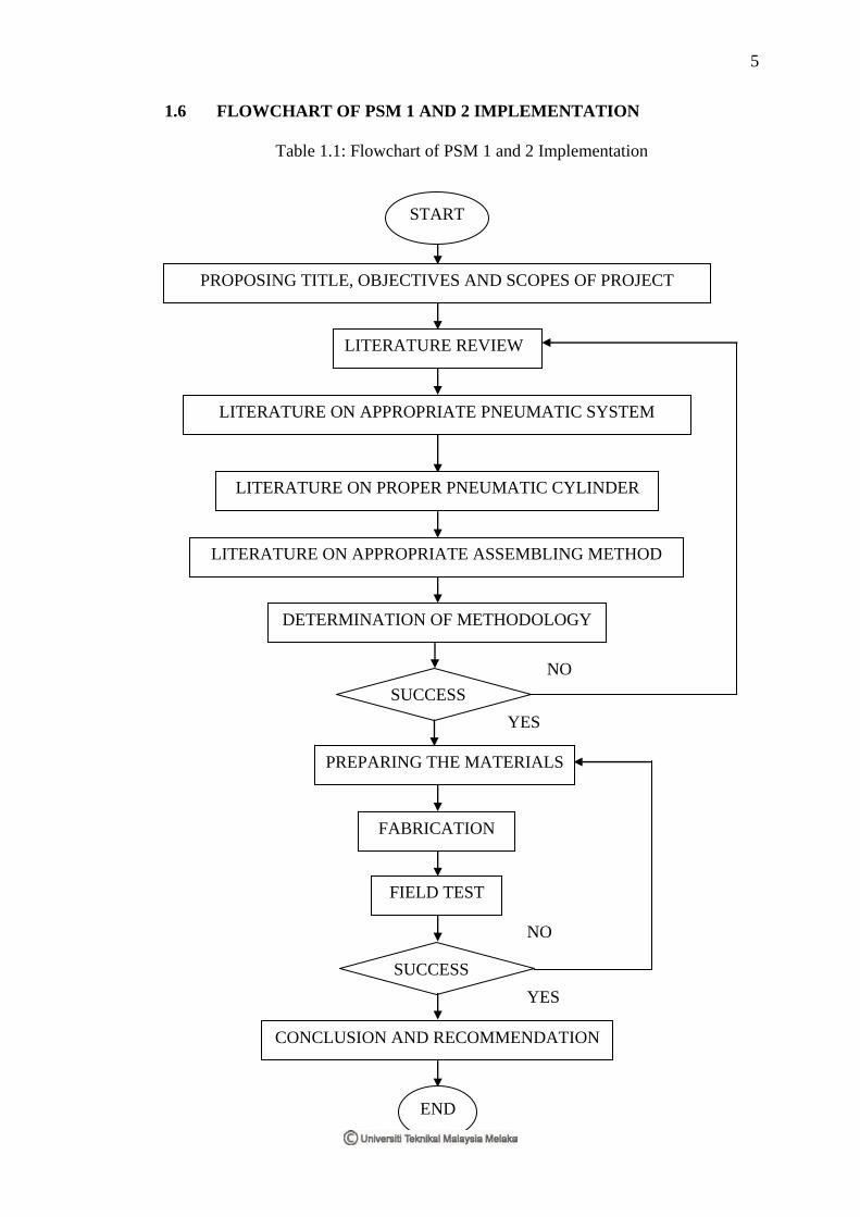
1.6 FLOWCHART OF PSM 1 AND 2 IMPLEMENTATION
Table 1.1: Flowchart of PSM 1 and 2 Implementation
SUCCESS
SUCCESS
YES
NO
YES
NO
START
END
PROPOSING TITLE, OBJECTIVES AND SCOPES OF PROJECT
LITERATURE REVIEW
LITERATURE ON APPROPRIATE PNEUMATIC SYSTEM
LITERATURE ON PROPER PNEUMATIC CYLINDER
LITERATURE ON APPROPRIATE ASSEMBLING METHOD
DETERMINATION OF METHODOLOGY
PREPARING THE MATERIALS
FABRICATION
FIELD TEST
CONCLUSION AND RECOMMENDATION

6
CHAPTER 2
LITERATURE REVIEW
2.1 INTRODUCTION
In the global world where transportations become surely essential for people,
we are realised that automotive industry plays a big role to produce a transportation
system such as cars, vans, motorcycles and others in order to ease people so that
people can utilise those things in a practical manner. Realise that automotive industry
grows rapidly, it is noticed that this field also plays a crucial task in producing
additional parts or tool kit in order to assist people when they are facing a situation
that cannot be predicted at the certain time.
One common device used in fluid power system can be referred to jack. As
its name implies, jack is a verb and can be defined as accordance to WordNet
homepage glossary as a device used to jack the car up so that people can change tyre
and do maintenance works. Besides, jack is also referred to a device used to lift an
object. Back in the early seventies century, jack named strand jacks were developed
which are recognised as the most sophisticated lifting devices. The basis principle of
strand jacks were originally from the Concrete Post Tensioning Principle which
stated that the jack can be compared to a single-part winch. In a strand jack, a bundle
of steel cables is guided through a hydraulic cylinder. [1]
7
2.2 FLUID POWER
Nowadays, fluid power is a vital technology among others which applies in
general applications such as generation, control and transmission of power by using
pressurised fluids. The term fluid refers to liquids or gases by means liquids are
called hydraulics which use oil or water as a medium in hydraulics system whereby
gases are defined as pneumatics which use air or other inert gases as a substance in
pneumatics system.
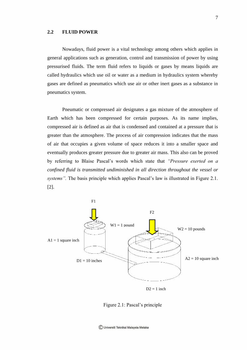
Pneumatic or compressed air designates a gas mixture of the atmosphere of
Earth which has been compressed for certain purposes. As its name implies,
compressed air is defined as air that is condensed and contained at a pressure that is
greater than the atmosphere. The process of air compression indicates that the mass
of air that occupies a given volume of space reduces it into a smaller space and
eventually produces greater pressure due to greater air mass. This also can be proved
by referring to Blaise Pascal’s words which state that “Pressure exerted on a
confined fluid is transmitted undiminished in all direction throughout the vessel or
systems”. The basis principle which applies Pascal’s law is illustrated in Figure 2.1.
[2].
Figure 2.1: Pascal’s principle
F1
F2
W1 = 1 pound
A1 = 1 square inch
A2 = 10 square inch
W2 = 10 pounds
D1 = 10 inches
D2 = 1 inch

8
Fluid power gives its own benefits to industry. One common advantage is that
fluid power can transmit energy either in electrical or mechanical or fluid power or a
combination of the three fields to acquire the most efficient in overall system. Fluid
power also provide many advantages to users which include multiplication and
variation of force in fractioning an amount of input forces into a big amount of
output forces. Other than that, fluid power gives easy and accurate control by
managing the large forces. [3]
2.3 RELATIONSHIPS BETWEEN PRESSURE, DIAMETER AND FORCE
The relationships between pressure, radius and force are defined as the force
exerted on the cylinder which contains pressure of compressed air. Since the author
has decided to use tubes, therefore the cross sectional area of tubes is less than the
piston since tubes occupies a hollow shape at the middle.
The relationship between the force exerted, pressure and diameter of the
tubes is as follows:
44
22
io ddpF
Where:
F represents the force exerted
p represents the maximum operating pressure
od represents the outer diameter of the tube
id represents the inner diameter of the tube
The usage of the above equation is crucial in determining the force value
since the author has come up with the initial and final calculation of load or weigh in
the Chapter 3. [4]

9
2.4 JACKS IN MARKET
It can be seen that the usage of jacks is among a practical tool since jacks can
be found at any hardware shops and offer variety of prices. Jacks in market ranges
from small ones to bigger ones as this applies for many applications. Jacks can be
sorted out into several groups such mechanical jacks, hydraulic jacks, air to hydraulic
jacks and air lifting bags.
2.4.1 MECHANICAL JACKS
One typical jack used in industry is mechanical jacks. Mechanical jacks are
used to lift heavy equipments whose weigh rated around 1.5 tons (1500 kg) or 3 tons
(3000 kg). Mechanical jacks are categorised into their classification include ratchet
jacks, screw jacks, super jacks, tank jacks, reel jacks, toe jacks, mine roof supports,
push/pull jacks, trench braces and spreader and planer jacks.
Ratchet jacks are widely used in oil fields, shipyards, mining operations,
construction, railroads and heavy-duty industrial maintenance. The jacks consist of
double-lever sockets for jacking in close quarters, multiple-tooth pawls for strength
and safety and adjustable spring links. The most practical of these jacks are 5-ton
ratchet jacks that are all mechanically identical and vary in stroke and height. The
use of 10-ton ratchet jacks is importability and is for lifting of 10 tons or less because
of their low handle effort. Figure 2.2 shows the hatchet jacks. [5]