hydraulic power steering system 7-100 - …accusteer.com/pdfs/ps7_100manual-web.pdfhydraulic power...
TRANSCRIPT


H Y D R A U L I C P O W E R S T E E R I N G S Y S T E M
PS7-100
TABLE OF CONTENTS
1. DESCRIPTION OF THE HRP PUMP .................................. p. 01
2. TECHNICAL SPECIFICATIONS and APPLICATION ........ p. 02
3. DESCRIPTION OF THE PS7-100 ...................................... p. 03 3.1 General 3.2 Motor 3.3 Pump 3.4 Valve Block and Valves
4. INSTALLATION ................................................................. p. 04 4.1 Mechanical 4.2 Hydraulic 4.3 Electrical
5. PREPARATION and TESTING ............................................ p. 06 5.1 Hydraulic Filling and Testing 5.2 Testing
6. NOTES ............................................................................. p. 07
7. DRAWINGS ..................................................................... p. 08 7.1 PS7-100 — System Connection Schematic 7.2 PS7-100 — Physical Top View Schematic 7.3 PS7-100 — Physical Side View Schematic 7.4 PS7-100 — Interconnection Diagram
i
This instruction manual is intended as a reference guide for correctly installing and maintaining the PS7-100 power assist steering system.
Please take time to read this manual to get a thorough understand-ing of the reversible pumpset and its relationship to a complete autopilot system.
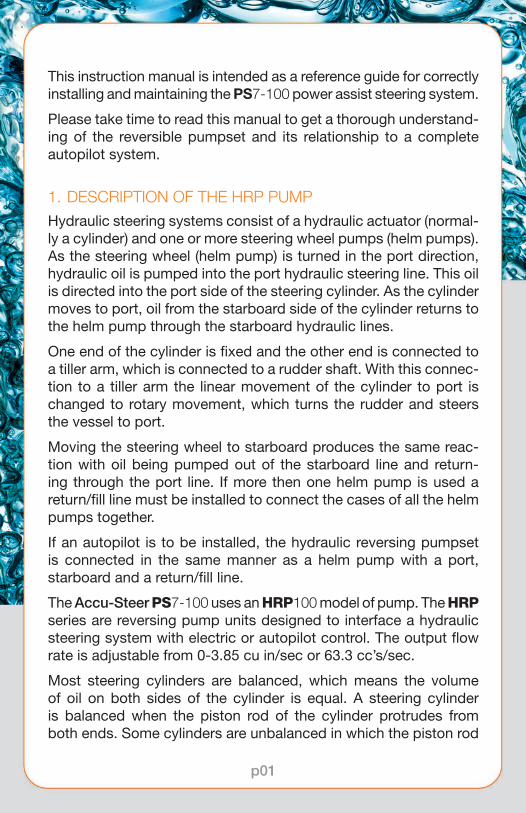
1. DESCRIPTION OF THE HRP PUMPHydraulic steering systems consist of a hydraulic actuator (normal-ly a cylinder) and one or more steering wheel pumps (helm pumps). As the steering wheel (helm pump) is turned in the port direction, hydraulic oil is pumped into the port hydraulic steering line. This oil is directed into the port side of the steering cylinder. As the cylinder moves to port, oil from the starboard side of the cylinder returns to the helm pump through the starboard hydraulic lines.
One end of the cylinder is fixed and the other end is connected to a tiller arm, which is connected to a rudder shaft. With this connec-tion to a tiller arm the linear movement of the cylinder to port is changed to rotary movement, which turns the rudder and steers the vessel to port.
Moving the steering wheel to starboard produces the same reac-tion with oil being pumped out of the starboard line and return-ing through the port line. If more then one helm pump is used a return/fill line must be installed to connect the cases of all the helm pumps together.
If an autopilot is to be installed, the hydraulic reversing pumpset is connected in the same manner as a helm pump with a port, starboard and a return/fill line.
The Accu-Steer PS7-100 uses an HRP100 model of pump. The HRP series are reversing pump units designed to interface a hydraulic steering system with electric or autopilot control. The output flow rate is adjustable from 0-3.85 cu in/sec or 63.3 cc’s/sec.
Most steering cylinders are balanced, which means the volume of oil on both sides of the cylinder is equal. A steering cylinder is balanced when the piston rod of the cylinder protrudes from both ends. Some cylinders are unbalanced in which the piston rod
p01

protrudes from one end only. These are common on some in-board and out-board drives and are usually referred to as side drives or simply unbalanced cylinders. This Accu-Steer HRP100 pumpset is capable of working with both balanced and unbalanced cylin-ders. When unbalanced cylinders are used it is recommended that a vented header tank is used to allow for the expansion and contraction from the unbalanced cylinder.
2. TECHNICAL SPECIFICATIONS and APPLICATION
The output flow rate of an electric pumpset determines the maxi-mum speed of the rudder. Under normal conditions a rudder speed of 10 to 16 seconds will provide the best steering results for most autopilot systems. It is therefore important to select the proper pumpset to optimize your autopilot operation.
First determine the volume of your steering cylinder. This is usually indicated in the instruction manual of your steering system.
If you have to calculate the volume of your cylinder manually you can use the following formula:
Volume = L(D2-d2)π÷4where:
L = length of stroke of cylinderD = internal diameter of cylinderd = diameter of piston rodπ = 3.14 (Pi)
ModelNumber
HRP100-12
HRP100-24
Voltage 12 VDC 12 VDC
Output/Sec
0-3.85cu in/sec
0-3.85cu in/sec
AverageMotorAmp
6-10 3-5
Weight 18 lbs8 kgs
18 lbs8 kgs
p02

The rudder speed, hard over to hard over (HOH), is determined by dividing the volume (cubic inches) of the cylinder by the output of the pumpset (cubic inches per second).
3. DESCRIPTION OF THE PS100 3.1 GENERAL The Accu-Steer PS7 valve block is mounted directly on
an HRP100 reversing pump to become a PS7-100 unit. Combined they provide power assist steering capability and autopilot/electric steering hydraulic drive. The PS7-100 unit is installed in the hydraulic steering system between the helm pump(s) and the steering cylinder. If the PS7-100 is not in the operational mode the steering oil from the helm(s) passes through to the steering cylinder. When the PS7-100 is acti-vated the oil from the helm passes through as before but the oil pressure and direction is sensed and the HRP reversing pump is operated in the same direction as the oil flow from the helm pump. As the helm operator turns the helm pump the reversing pump will continue to operate. When the helm wheel is stopped the PS7-100 sensors turn off the reversing pump.
3.2 MOTOR The electric motor has the following features:
• Ignition protected (UL 1500 and SAE-1171)
• Ball bearing shaft supports both ends
• Extended motor shafting eliminating the pump/motor coupling
• Machined pilot bore ensuring aligned pump/motor mounting
3.3 PUMP The reversing gear pumps (HRP’s) use gerotor style pump unit.
The gerotor gear was used because of its quiet operation and its efficient pumping capabilities.
The gears are driven directly from the extended motor shaft thereby eliminating the need for a pump/motor shaft coupling.
The shaft is supported by the motor ball bearing on one side and a hard anodized aluminum end plate on the other side.
p03

The gerotor pump is a two-piece gear assembly with an eccen-tric ring. Proper clearances and alignments are maintained through CNC precision machining.
Valve block sealing is accomplished using O-ring style seals.
The shaft seal is accomplished using a rubber shaft seal rated at 50 psi. This shaft seal is connected to the tank/return line pump chamber. If this tank port is connected to a steering line or is over pressurized it may cause this seal to fail. See the installation instructions for more details.
3.4 VALVE BLOCK and VALVES The valve block is an aluminum block, precision machined to
house the valves, direct the oil and serve as the endplate for the gear pump. The pump end plate is referenced to the valve block with locator pins to ensure the proper alignment.
The suction make-up valves are located between the return line port and the pump output internal ports. These allow the pump to “breathe” properly in the event of air from the steering lines entering the pumpset.
The output check valves are part of what is called a lockvalve assembly. The lockvalve assembly consists of two output check valves and a lockvalve spool. In the non-running position the spring operated check valves remain closed, isolating the pump from the steering system. The spring action of the check valves holds the lockvalve spool in the mid-closed position.
The end plate houses the pump shaft guide and aligns the pump.
4. INSTALLATION 4.1 MECHANICAL The PS7-100 pumpset must be mounted on a horizontal shelf
or bracket with a solid foundation. The pump can be bolted or screwed down with the foot bracket. The pumpset should be close to and below the steering lines for ease of connections and bleeding.
4.2 HYDRAULIC Before connection to the hydraulic lines, ensure that all the
p04
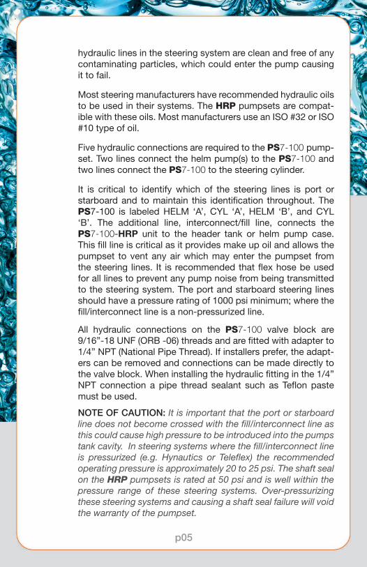
hydraulic lines in the steering system are clean and free of any contaminating particles, which could enter the pump causing it to fail.
Most steering manufacturers have recommended hydraulic oils to be used in their systems. The HRP pumpsets are compat-ible with these oils. Most manufacturers use an ISO #32 or ISO #10 type of oil.
Five hydraulic connections are required to the PS7-100 pump-set. Two lines connect the helm pump(s) to the PS7-100 and two lines connect the PS7-100 to the steering cylinder.
It is critical to identify which of the steering lines is port or starboard and to maintain this identification throughout. The PS7-100 is labeled HELM ‘A’, CYL ‘A’, HELM ‘B’, and CYL ‘B’. The additional line, interconnect/fill line, connects the PS7-100-HRP unit to the header tank or helm pump case. This fill line is critical as it provides make up oil and allows the pumpset to vent any air which may enter the pumpset from the steering lines. It is recommended that flex hose be used for all lines to prevent any pump noise from being transmitted to the steering system. The port and starboard steering lines should have a pressure rating of 1000 psi minimum; where the fill/interconnect line is a non-pressurized line.
All hydraulic connections on the PS7-100 valve block are 9/16”-18 UNF (ORB -06) threads and are fitted with adapter to 1/4” NPT (National Pipe Thread). If installers prefer, the adapt-ers can be removed and connections can be made directly to the valve block. When installing the hydraulic fitting in the 1/4” NPT connection a pipe thread sealant such as Teflon paste must be used.
NOTE OF CAUTION: It is important that the port or starboard line does not become crossed with the fill/interconnect line as this could cause high pressure to be introduced into the pumps tank cavity. In steering systems where the fill/interconnect line is pressurized (e.g. Hynautics or Teleflex) the recommended operating pressure is approximately 20 to 25 psi. The shaft seal on the HRP pumpsets is rated at 50 psi and is well within the pressure range of these steering systems. Over-pressurizing these steering systems and causing a shaft seal failure will void the warranty of the pumpset.
p05

4.3 ELECTRICAL The motors used on the HRP pumpsets are ignition protected,
built to conform to UL-1500 and SAE-1171 standards.
5. PREPARATION AND TESTING 5.1 HYDRAULIC FILLING AND TESTING When installing a pumpset it is recommended that the system
be flushed to ensure that the oil is clean and free of contamina-tion throughout the hydraulic steering system.
After the hydraulic and electrical connection have been made allow sufficient time for the pump and the lines to fill with oil. Operate the pumpset and note the HOH time. This time varies with the type of steering system and autopilot used.
5.2 TESTING Most new autopilot systems will perform this test during their
dockside set-up procedures.
p06

6. NOTES
....................................................................................................................
....................................................................................................................
....................................................................................................................
....................................................................................................................
....................................................................................................................
....................................................................................................................
....................................................................................................................
....................................................................................................................
....................................................................................................................
....................................................................................................................
....................................................................................................................
....................................................................................................................
....................................................................................................................
....................................................................................................................
....................................................................................................................
....................................................................................................................
....................................................................................................................
....................................................................................................................
....................................................................................................................
....................................................................................................................
....................................................................................................................
....................................................................................................................
....................................................................................................................
....................................................................................................................
....................................................................................................................
....................................................................................................................
p07

7. DRAWINGS 7.1 PS7-100 SYSTEM CONNECTION SCHEMATIC
Shipping weight: 28 lbs • Dimensions: 6” (w) x 13” (l) x 8” (h)
ACCU-STEER, INC.HRP 100SN - XXXX
HE
LM P
UM
P FLO
WA
DJU
STM
EN
T
CYL ‘A’
HELM ‘A’
CYL ‘B’
HELM ‘B’FILL / TANK
HR
P10
0 -
12/2
4
p08

7.2 PS7-100 PHYSICAL TOP VIEW SCHEMATIC
7.3 PS7-100 PHYSICAL SIDE VIEW SCHEMATIC
AC
CU
-STEER
, INC
.H
RP 100
SN
- XXXX
HE
LM ‘A
’H
ELM
‘B’ FI
LL /
TA
NK
FLOW ADJUSTMENT
CY
L ‘A
’C
YL
‘B’
HRP100 - 12/24
AP
PR
OX
6”
APPROX 13”
02ORB
02ORB
INTERNAL PRESSURERELIEF
FLOWADJUST
IN FROM HELM PUMP
FILL LINE OUT TO CYCLINDERS
AP
PR
OX
8”
p09

7.4 PS7-100 INTERCONNECTION DIAGRAM
PS7-100
p10

7.4 PS7-100 INTERCONNECTION DIAGRAM (CON’D)
Please note:An autopilot and jog control may both be connected to the Accu-Steer PS7-100 at the same time. In this case, however, the autopilot and the jog inputs must be isolated from each other either through a switch or through isolation diodes. Please contact Accu-Steer for further information.
PS7-100 PS7-100
PS7-100 PS7-100
p11

