57 steering - roverworld · 57 steering braking system contents page -overhaul manual steering box...
TRANSCRIPT
Section Number
70
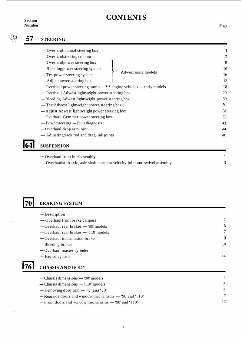
57 STEERING
BRAKING SYSTEM
CONTENTS Page
-Overhaul manual steering box -Overhaul steering column -Overhaul power steering box -Bleeding power steering system -Test power steering system -Adjust power steering box - Overhaul power steering pump - V8 engine vehicles - early models - Overhaul Adwest lightweight power steering box - Bleeding Adwest lightweight power steering box -Test Adwest lightweight power steering box - Adjust Adwest lightweight power steering box - Overhaul Gemmer power steering box -Power steering - fault diagnosis - Overhaul drop arm joint -Adjusting track rod and drag link joints
Adwest early models I I
164 I SUSPENSION
1 3 8
16 16 18 18 20 30 30 31 32 43 44
46
- Overhaul front hub assembly -Overhaul stub axle, axle shaft constant velocity joint and swivel assembly
1 3
- Description ~, -Overhaul front brake calipers
- Overhaul rear brakes - ‘90’ models - Overhaul rear brakes - ‘1 10’ models - Overhaul transmission brake - Bleeding brakes - Overhaul master cylinder -Fault diagnosis
n
I76 I CHASSIS AND BODY
1
2 6 7 8
10 11 14
- Chassis dimensions - ‘90’ models - Chassis dimensions - ‘110’ models - Kemoving door trim - ‘90’ ana ’iiW - Rearside doors and window mechanisms - ‘90’ and ‘1 10’ - Front doors and window mechanisms - ‘90’ and ‘1 10’
- 1 3 6 7
12
. .
1
INTRODUCTION
This Workshop Manual covers the Land Rover Ninety and One Ten range of vehicles. It is primarily designed to assist skilled technicians in the efficient repair and maintenance of Land Rover vehicles.
Using the appropriate service tools and carrying out the procedures as detailed will enable the operations to be completed within the time stated in the 'Repair Operation Times'
The Manual has been produced in separate books; this allows the information to be distributed throughout the specialist areas of the modern service facility.
A table of contents in Book 1 lists the major components and systems together with thc section and book numbers. The cover of each book details thc sections contained within that book.
The title page of each book carries the part numbers required to order replacement books, binders or complete Service Manuals. This can be done through the normal channels.
REFERENCES References to the left- or right-hand side in the manual are made when viewing the vehicle from the rear. With the engine and gearbox assembly removcd, the water pump end of the engine is referred to as the front. To reduce repetition, operations covered in this manual do not include referencc to testing the vehicle aftcr rcpair. It is essential that work is inspected and tested aftcr completion and if necessary a road test of the vehicle is carried out 6'": T
particularly where safety relatcd items are concerned. ' .t
DIMENSIONS The dimensions quoted are to design engineering specification. Altcrnative unit equivalents, shown in brackets ColJowing the dimensions, have bccn converted from the original specification. During the period of running-in from new, certain adjustments may vary from the specification figurcs given in this Manual. These adjustments will be re-set by t h e Distributor or Dealer at the After Sales Service, and thereafter should bc maintained at the figures specified in the Manual.
REPAIRS AND REPLACEMENTS When replacement parts are required i t is essential that on ly Land Rover parts are used. Attcntion is particularly drawn to the following points concerning repairs and the fitting of replacement parts and accessories: Safety features embodied in the vehicle may be impaircd if other than Land Rover parts are fitted. In certain territories, legislation prohibits the fitting of parts not to the vehicle manufacturer's specification. Torque wrench &++. sctting figures given in the Repair Operation Manual must be strictly adhered to. Locking devices, where specified, ; must bc fitted. If the efficicncy of a locking device is impaired during removal it must be renewed. Owners purchasing accessories while travelling abroad should ensure that the accessory and its fitted location on the vehicle conform to mandatory requirements existing in their country of origin. The terms of the Owners Service Statement may be invalidatcd by the fitting of other than Land Rover parts. All Land Rover parts have the full backing of the Owners Service Statement. Land Rover Distributors and Dealers are obliged to supply only Land Rover service parts.
POISONOUS SUBSTANCES Many liquids and other substances used in motor vehicles arc poisonous and should under no circumstances be consumed and should as far as possible be kept away from open wounds. These substances among others include antifreeze, brake fluid, fucl, windscreen washer additives, lubricants and various adhesives.
FUEL HANDLING PRECAUTIONS The following information provides basic precautions which must be observed if petrol (gasoline) is to be handled
This information is issued for basic guidance only, and in any case of doubt appropriate enquiries should be made of your local Fire Officer.
safely. It also outlines the other areas of risk which must not be ignored. g-; ='
I1
GENERAL PetroVgasoline vapour is highly flammable and in confined spaces is also very explosive and toxic. When petrol/gasoline evaporates it produces 150 times its own volume in vapour, which when diluted with air becomes a readily ignitable mixture. The vapour is heavier than air and will always fall to the lowest level. It can readily be distributed throughout a workshop by air current, consequently, even a small spillage of petrol/gasoline is
... , ~
;;;,:ii.,;:: .... , .C I._..1 .. , .. . ... ' '_ potentially very dangerous.
Always have a fire extinguisher containing FOAM CO2 GAS, or POWDER close at hand when handling or draining fuel, o r when dismantling fuel systems and in areas where fuel containers are stored. Always disconnect the vehicle battery BEFORE carrying out dismantling or draining work on a fuel system. Whenever petrol/gasoline is being handled, drained or stored, or when fuel systems are being dismantled all forms of ignition must be extinguished or removed, any head-lamps used must be flameproof and kept clear of spillage.
NO ONE SHOULD B E PERMITTED TO REPAIR COMPONENTS ASSOCIATED WITH PETROL/ GASOLINE WITHOUT FIRST HAVING HAD SPECIALIST TRAINING.
FUEL TANK DRAINING
WARNING: PETROL/GASOLINE MUST NOT BE EXTRACTED OR DRAINED FROM ANY VEHICLE WHILST IT IS STANDING OVER A PIT.
Draining or extracting petrol/gasoline from vehicle fuel tank must be carried out in a well ventilated area. The receptacle used to contain the petrol/gasoline must be more than adequate for the full amount of fuel to be extracted or drained. The receptacle should be clearly marked with its contents, and placed in a safe storage area which meets the requirements of local authority regulations. WHEN PETROL/GASOLINE HAS BEEN EXTRACTED OR DRAINED FROM A FUEL TANK THE PRECAUTIONS GOVERNING NAKED LIGHTS AND IGNITION SOURCES SHOULD BE MAINTAINED.
FUEL TANK REMOVAL On vchiclcs where the fuel line is secured to the fuel tank outlet by a spring steel clip, it is recommended that such clips are reieased before the fuel line is disconnected or the fuel tank unit is removed. This procedure will avoid the possibility of residual petrol fumes in the fuel tank being ignited when the clips are released. As an added precaution fuel tanks should have a PETROWGASOLINE VAPOUR warning label attached to them as soon as they are removed from the vehicle.
FUEL TANK REPAIR Under no circumstances should a repair to any tank involving heat treatment be carried out without first rendering the tank SAFE, by using one of the following methods:
STEAMING: With the filler cap and tank unit removed, empty the tank. Steam the tank for at least two hours with low pressure steam. Position the tank so that condensation can drain away freely, ensuring that any sedimcnt and sludge not volatised by the steam, is washed out during the steaming process. BOILING: With the filler cap and tank unit removed, empty the tank. Immerse the tank completely in boiling water containing an effective alkaline degreasing agent or a detergent, with the water filling and also surrounding the tank for at least two hours. After steaming or boiling a signed and dated label to this effect should be attached to the tank.
. ..
SPECIFICATION Purchasers are advised that the specification details set out in this Manual apply to a range of vehicles and not to any one. For the specification of a particular vehicle, purchasers should consult their Distributor or Dealer.
The Manufacturers reserve the right to vary their specifications with or without notice, and at such times and in such manner as they think fit. Major as well as minor changes may be involved in accordance with the Manufacturer's policy of constant product improvement.
Whilst every effort is made to ensure the accuracy of the particulars contained in this Manual, ncither thc Manufacturer nor the Distributor or Dealer, by whom this Manual is supplied, shall in any circumstances be held liable for any inaccuracy or the consequences thereof.
COPYRIGHT @ Land Rover Limited 1984
, , . . .. .I ., . . . . ... . . . . : '
All rights reserved. No part of this publication may be produced, stored in a retrieval system or transmitted in any form, electronic, mechanical, photocopying, recording or other means without prior written permission of Land Rover Limited, Service Department, Solihull, England.
, .. ",.
... 111
. Special Service The use of approved special service tools is important. They are essential i f service operations are to be carried out efficiently, and safcly. The amount of time which they save can be considerable.
Every special tool is designed with the close co-operation of Land Rover Ltd., and no tool is put into production which has not been tested and approved by us. New tools are only introduced where an operation cannot be satisfactorily carried out using existing tools or standard equipment. The user is therefore assured that the tool is necessary and that it will perform accurately, efficiently and safely.
Special tools bulletins will be issued periodically giving details of new tools as they are introduced.
All orders and enquiries from the United Kingdom should be sent direct to V. L. Churchill. Overseas orders should be placed with the local V. L. Churchill distributor, where one exists. Countries where there is no distributor may order direct from V. L. Churchill Limited, PO Box 3 Daventry, Northants, England NNl l4NF.
The tools recommended in this Workshop Manual are listed in a multi-language, illustrated catalogue obtainable from Messers. V. L. Churchill at the above address under publication number 2217/2/84 or from Land Rover Ltd., under part number LSM0052TC from the following address, Land Rover Merchandising Service, P.O. Box 534, Erdington, Birmingham B24 OQS.
STEERING
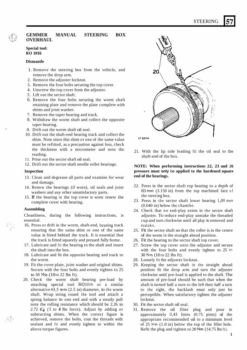
GEMMER MANUAL STEERING BOX OVERHAUL
Special tool: RO 1016
Dismantle
1. Remove the steering box from the vehicle, and
2. Remove the adjuster locknut. 3. Remove the four bolts securing the top cover. 4. Unscrew the top cover from the adjuster. 5. Lift out the sector shaft. 6. Remove the four bolts securing the worm shaft
retaining plate and remove the plate complete with shims and joint washer.
remove the drop arm.
7. Remove the taper bearing and track. 8. Withdraw the worm shaft and collect the opposite
taper bearing. .9. Drift out the worm shaft oil seal. 10. Drift out the shaft-end bearing track and collect the
shim. Note since this shim or one of the same value must be refitted, as a precaution against loss, check the thickness with a micrometer and note the reading.
11. Prise out the sector shaft oil seal. 12. Drift out the sector shaft needle roller bearings.
Inspection 13. Clean and degrease all parts and examine for wear
14. Renew the bearings (if worn), oil seals and joint
15. If the bearing in the top cover is worn renew the
Assembling Cleanliness, during the following instructions, is essential. 16. Press or drift in the worm, shaft-end, bcaring track
ensuring that the same shim or one of the same value is fitted behind the track. It is essential that the track is fitted squarely and pressed fully home.
17. Lubricate and fi t the bearing to the shaft and insert the shaft into the box.
18. Lubricate and fit the opposite bearing and track to the worm.
19. Fit the cover plate, joint washer and original shims. Secure with the four bolts and evenly tighten to 25 to 30 Nm (18 to 22 Ibs ft).
20. Check the worm shaft bearing pre-load by attaching special tool R01016 or a similar alternative 63,5 mm (2.5 in) diameter, to the worm shaft. Wrap string round the tool and attach a spring balance to one end and with a steady pull note the rolling resistance which should be 2.26 to 2.72 Kg ( 5 to 6 Ibs force). Adjust by adding or subtracting shims. When the correct figure is achieved, remove the bolts, coat the threads with sealant and fit and evenly tighten to within the above torque figures.
-
and damage.
washers and any other unsatisfactory parts.
complete cover with bearing.
57
ST 887M
21. With the lip side leading fit the oil seal to the shaft-end of the box.
NOTE: When performing instructions 22, 23 and 26 pressure must only be applied to the hardened square end of the bearings.
22. Press in the sector shaft top bearing to a depth of 83 mm (3.150 in) from the top machined face o f the steering box.
23. Press in the sector shaft lower bearing 1,OO mm (0.040 in) below the chamfer.
24. Check that no end-play exists in the sector shaft adjuster. To reduce end-play unstake the threaded cup and turn clockwise until all play is removed and restake.
25. Fit the sector shaft so that the roller is in the centre of the worm in the straight ahead position.
26. Fit the bearing to the sector shaft top cover. 27. Screw the top cover onto the adjuster and secure
with the four bolts and evenly tighten to 25 to 30 Nm (18 to 22 Ibs ft).
28. Loosely fit the adjuster locknut. 29. Keeping the sector shaft in the straight ahead
position fit the drop arm and turn the adjuster clockwise until pre-load is applied to the shaft. The amount of pre-load should be such that when the shaft is turned half a turn to the left then half a turn to the right, the backlash must only just be perceptible. When satisfactory tighten the adjuster locknut.
30. Fit the sector shaft oil seal. 31. Remove the oil filter plug and pour in
approximately 0,43 litres (0.75 pints) of the appropriate recommended oil to a minimum level of 25 mm (1.0 in) below the top of the filler hole. Refit the plug and tighten to 20 Nm (14.75 Ibs ft) .
1
157 I STEERING
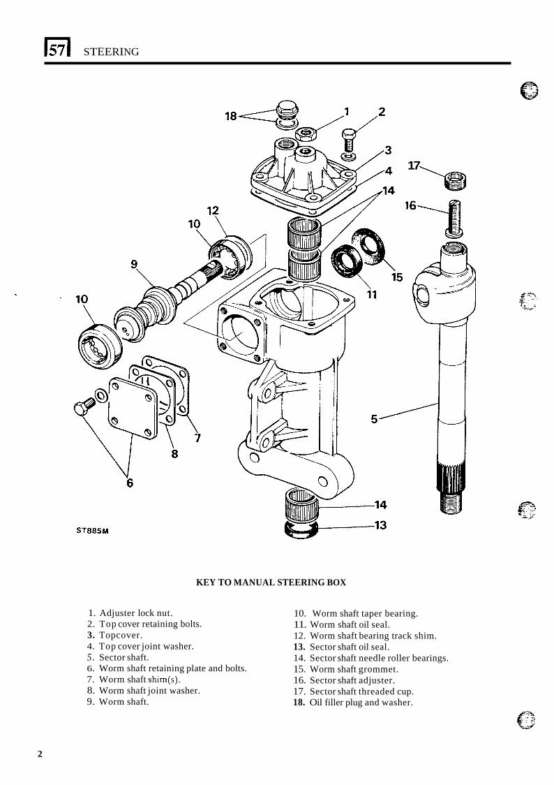
ST885M
KEY TO MANUAL STEERING BOX
17
1. Adjuster lock nut. 2. Top cover retaining bolts. 3. Topcover. 4. Top cover joint washer. 5. Sector shaft. 6. Worm shaft retaining plate and bolts. 7. Worm shaft shim(s). 8. Worm shaft joint washer. 9. Worm shaft.
10. Worm shaft taper bearing. 11. Worm shaft oil seal. 12. Worm shaft bearing track shim. 13. Sector shaft oil seal. 14. Sector shaft needle roller bearings. 15. Worm shaft grommet. 16. Sector shaft adjuster. 17. Sector shaft threaded cup. 18. Oil filler plug and washer.
2
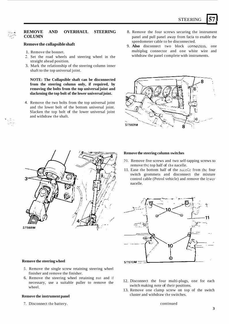
STEERING I57 I r I . , ... REMOVE AND OVERHAUL STEERING 8. Remove the four screws securing the instrument
panel and pull panel away from facia to enable the COLUMN : I . , I , -_. .L *
Remove the collapsible shaft speedometer cable to be disconnected.
9. Also disconnect two block conncctors. one 1. Remove the bonnet. 2. Set the road wheels and steering wheel in the
3. Mark the relationship of the steering column inner
multiplug connector and one white wire and withdraw the panel complete with instruments.
straight ahead position.
shaft to the top universal joint.
4.
NOTE: The Collapsible shaft can be disconnected from the steering column only, if required, by removing the bolts from the top universal joint and slackening the top bolt of the lower universal joint.
Remove the two bolts from the top universal joint and the lower bolt of the bottom universal joint. Slacken the top bolt of the lower universal joint and withdraw the shaft.
Remove the steering wheel
5 . Remove the single screw retaining steering wheel finisher and remove the finisher.
6. Remove the steering wheel retaining n u t and i f necessary, use a suitable puller to remove the wheel.
Remove the instrument panel
7. Disconnect the battery.
Remove the steering column switches
10. Remove five screws and two self-tapping screws to remove the top half of t h e nacelle.
11. Ease the bottom half of the nacellc from the four switch grommets and disconnect the mixture control cable (Petrol vehicle) and remove the lowcr nacelle.
12. Disconnect the four multi-plugs, one for each
13. Remove one clamp screw on top of the switch switch making note of their positions.
cluster and withdraw the switches.
continued 3
STEERING
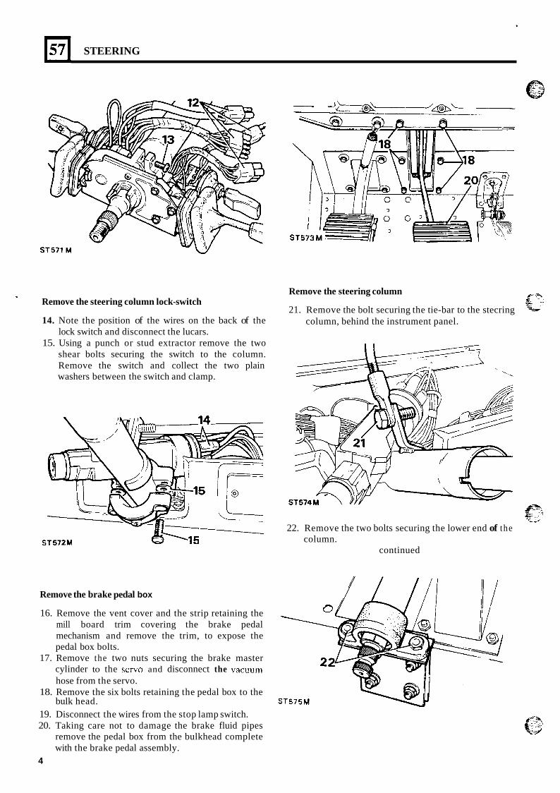
Remove the steering column lock-switch
14. Note the position of the wires on the back of the lock switch and disconnect the lucars.
15. Using a punch or stud extractor remove the two shear bolts securing the switch to the column. Remove the switch and collect the two plain washers between the switch and clamp.
b ST572M
Remove the steering column
21. Remove the bolt securing the tie-bar to the stecring column, behind the instrument panel.
Remove the brake pedal box
16. Remove the vent cover and the strip retaining the mill board trim covering the brake pedal mechanism and remove the trim, to expose the pedal box bolts.
17. Remove the two nuts securing the brake master cylinder to the servo and disconnect the vacuum hose from the servo.
18. Remove the six bolts retaining the pedal box to the
19. Disconnect the wires from the stop lamp switch. 20. Taking care not to damage the brake fluid pipes
remove the pedal box from the bulkhead complete with the brake pedal assembly.
bulk head. ST575M
4
22. Remove the two bolts securing the lower end of the
continued column.
STEERING
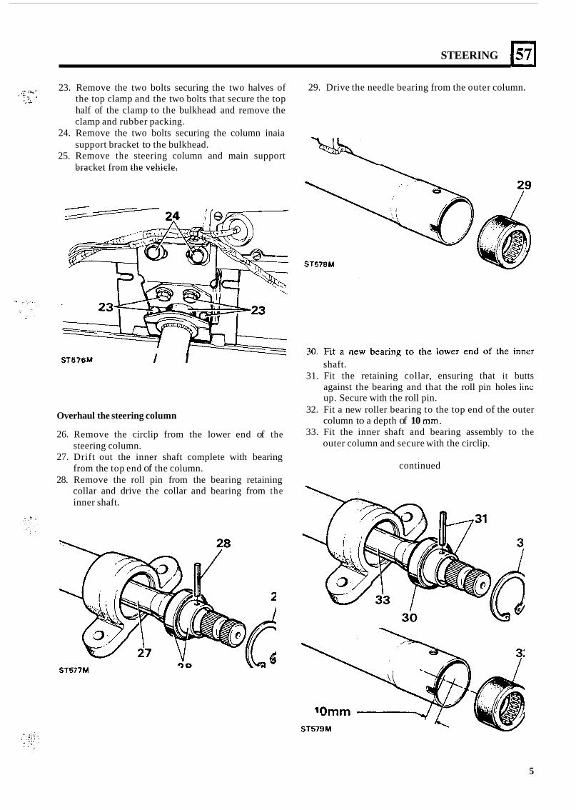
~ ,:' . I , _ ( . 23. Remove the two bolts securing the two halves of the top clamp and the two bolts that secure the top half of the clamp to the bulkhead and remove the clamp and rubber packing.
24. Remove the two bolts securing the column inaia support bracket to the bulkhead.
25. Remove the steering column and main support bracket from the vehicle.
29. Drive the needle bearing from the outer column. C . " . *. I -
ST576M t I
Overhaul the steering column
26. Remove the circlip from the lower end of the steering column.
27. Drift out the inner shaft complete with bearing from the top end of the column.
28. Remove the roll pin from the bearing retaining collar and drive the collar and bearing from the inner shaft.
ST577M
shaft. 31. Fit the retaining collar, ensuring that it butts
against the bearing and that the roll pin holes linc up. Secure with the roll pin.
32. Fit a new roller bearing to the top end of the outer column to a depth of 10 mm.
33. Fit the inner shaft and bearing assembly to the outer column and secure with the circlip.
continued
ST579M
5
Ei STEERING
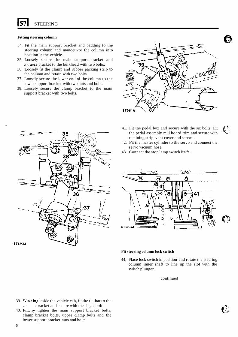
Fitting steering column
34. Fit the main support bracket and padding to the steering column and manoeuvre the column into position in the vehicie.
35. Loosely secure the main support bracket and harness bracket to the bulkhead with two bolts.
36. Loosely fi t the clamp and rubber packing strip to the column and retain with two bolts.
37. Loosely secure the lower end of the column to the lower support bracket with two nuts and bolts.
38. Loosely secure the clamp bracket to the main support bracket with two bolts.
-- 41. Fit the pedal box and secure with the six bolts. Fit
the pedal assembly mill board trim and secure with retaining strip, vent cover and screws.
42. Fit the master cylinder to the servo and connect the servo vacuum hose.
43. Connect the stop lamp switch leads.
Fit steering column lock switch
44. Place lock switch in position and rotate the steering column inner shaft to line up the slot with the switch plunger.
continued
39. Wn-bing inside the vehicle cab, fit the tie-bar to the cc
40. Fir.. .ly tighten the main support bracket bolts, clamp bracket bolts, upper clamp bolts and the lower support bracket nuts and bolts.
n bracket and secure with the single bolt.
6
* .. . , .. .. . .. .
STEERING
I . .
57
... ? . . . . . ... . .
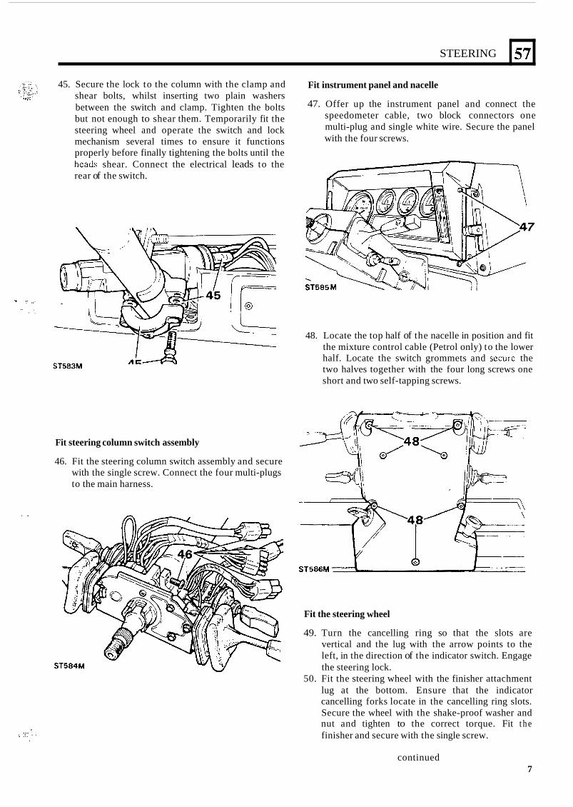
45. Secure the lock to the column with the clamp and shear bolts, whilst inserting two plain washers between the switch and clamp. Tighten the bolts but not enough to shear them. Temporarily fit the steering wheel and operate the switch and lock mechanism several times to ensure it functions properly before finally tightening the bolts until the heads shear. Connect the electrical leads to the rear of the switch.
ST583M
Fit steering column switch assembly
46. Fit the steering column switch assembly and secure with the single screw. Connect the four multi-plugs to the main harness.
Fit instrument panel and nacelle
47. Offer up the instrument panel and connect the speedometer cable, two block connectors one multi-plug and single white wire. Secure the panel with the four screws.
7
48. Locate the top half of the nacelle in position and fit the mixture control cable (Petrol only) to the lower half. Locate the switch grommets and securc the two halves together with the four long screws one short and two self-tapping screws.
Fit the steering wheel
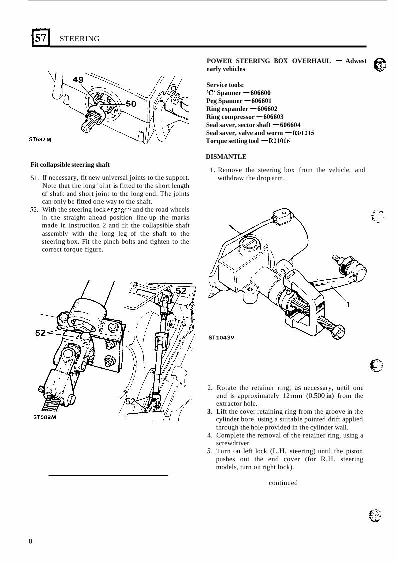
49. Turn the cancelling ring so that the slots are vertical and the lug with the arrow points to the left, in the direction of the indicator switch. Engage the steering lock.
50. Fit the steering wheel with the finisher attachment lug at the bottom. Ensure that the indicator cancelling forks locate in the cancelling ring slots. Secure the wheel with the shake-proof washer and nut and tighten to the correct torque. Fit t h e finisher and secure with the single screw.
continued 7
STEERING
ST587 M
Fit collapsible steering shaft
POWER STEERING BOX OVERHAUL - Adwest e early vehicles
Service tools: 'C' Spanner - 606600 Peg Spanner - 606601 Ring expander - 606602 Ring compressor - 606603 Seal saver, sector shaft - 606604 Seal saver, valve and worm - R01015 Torque setting tool - R01016
DISMANTLE
1. Remove the steering box from the vehicle, and 51.
52.
If necessary, fit new universal joints to the support. Note that the long joint is fitted to the short length of shaft and short joint to the long end. The joints can only be fitted one way to the shaft. With the steering lock engagcd and the road wheels in the straight ahead position line-up the marks
withdraw the drop arm.
made in instruction 2 and fit the collapsible shaft \ assembly with the long leg of the shaft to the steering box. Fit the pinch bolts and tighten to the correct torque figure.
ST 104 3 M
2. Rotate the retainer ring, as necessary, until one end is approximately 12 mm (0.500 in) from the extractor hole.
3. Lift the cover retaining ring from the groove in the cylinder bore, using a suitable pointed drift applied through the hole provided in the cylinder wall.
4. Complete the removal of the retainer ring, using a screwdriver.
5. Turn on left lock (L.H. steering) until the piston pushes out the end cover (for R.H. steering models, turn on right lock).
ST588M
continued
8
STEERING
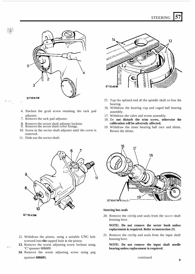
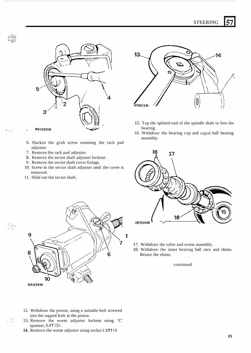
15. Tap the splined end of the spindle shaft to free the bearing.
3
57
16. Withdraw the bearing cup and caged ball bearing
17. Withdraw the valve and worm assembly. 18. Do not disturb the trim screw, otherwise the
calibration will be adversely affected. 19. Withdraw the inner bearing ball race and shims.
Retain the shims.
6. Slacken the grub screw retaining the rack pad
7. Remove the rack pad adjuster. 8. Remove the sector shaft adjuster locknut. 9. Remove the sector shaft cover fixings.
assembly. adjuster.
10. Screw in the sector shaft adjuster until the cover is removed.
11. Slide out the sector shaft.
ST 10 4 5 M
l6 R 17
Steering box seals
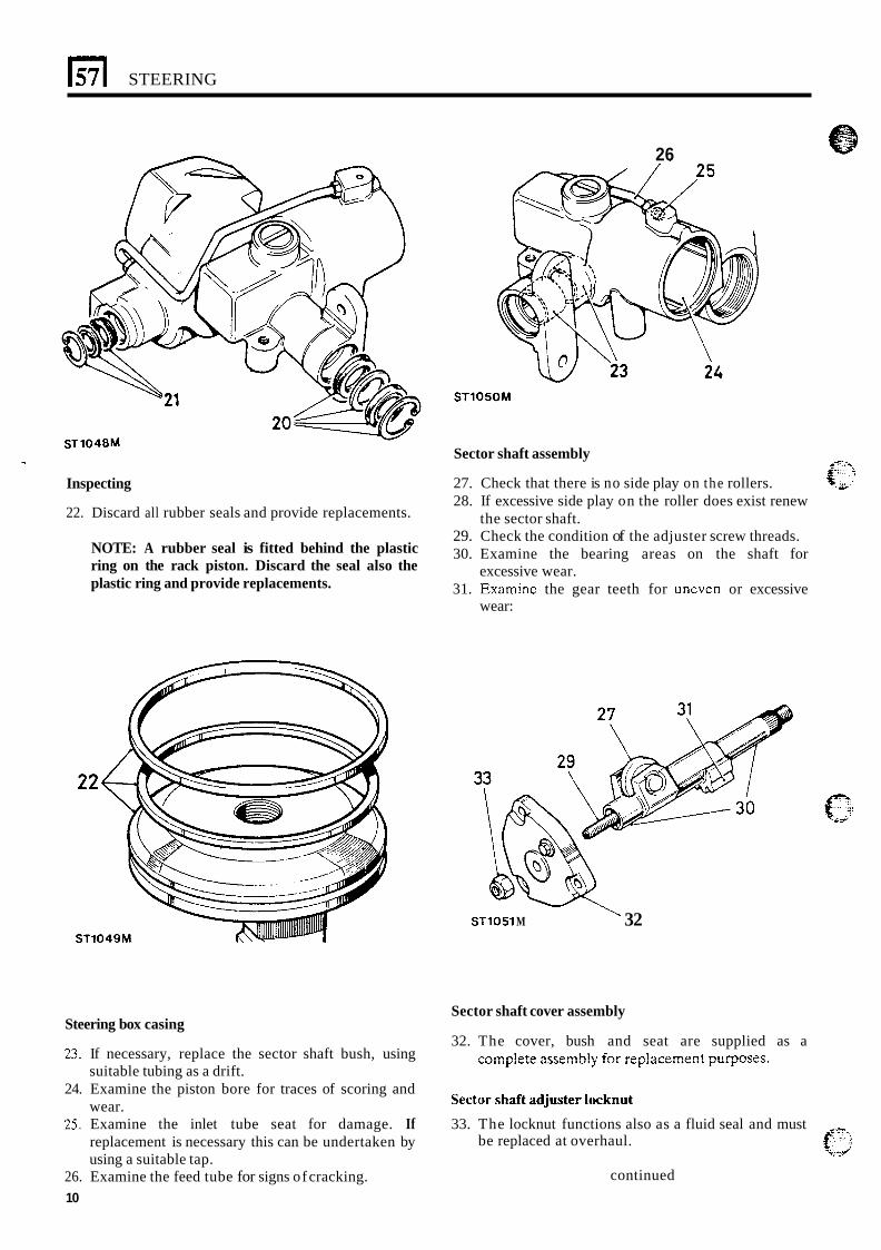
20. Remove the circlip and seals from the scctor shaft housing bore.
NOTE: Do not remove the sector bush unless replacement is required. Refer to instruction 23.
21. Remove the circlip and seals from the input shaft housing bore.
NOTE: Do not remove the input shaft needle bearing unless replacement is required.
12. Withdraw the piston, using a suitable UNC bolt
13. Remove the worm adjusting screw locknut using
14. Remove the worm adjusting screw using peg
screwed into the tapped hole in the piston.
‘C’ spanner 606600.
spanner 606601. continued
.! .’
9
STEERING
26
S T 1 0 5 0 M
Sector shaft assembly
27. Check that there is no side play on the rollers. 28. If excessive side play on the roller does exist renew
29. Check the condition of the adjuster screw threads. 30. Examine the bearing areas on the shaft for
31. Examinc the gear teeth for uneven or excessive
the sector shaft.
excessive wear.
wear:
Inspecting
22. Discard all rubber seals and provide replacements.
NOTE: A rubber seal is fitted behind the plastic ring on the rack piston. Discard the seal also the plastic ring and provide replacements.
22
ST1049M STlOSl M ' 32
Sector shaft cover assembly
32. The cover, bush and seat are supplied as a Steering box casing
23. If necessary, replace the sector shaft bush, using c=mp!ete assemb!j! fe: :ep!ace!??en? pllrpnses. suitable tubing as a drift.
wear.
replacement is necessary this can be undertaken by using a suitable tap.
24. Examine the piston bore for traces of scoring and
25. Examine the inlet tube seat for damage. If 33. The locknut functions also as a fluid seal and must
sector shaft adjuster locknut
e-.. be replaced at overhaul. %:.:/
26. Examine the feed tube for signs of cracking. 10
continued
STEERING
:::
., .,
.. . ,, .-. . .. . . . . . . .- . _ _ .' . . .
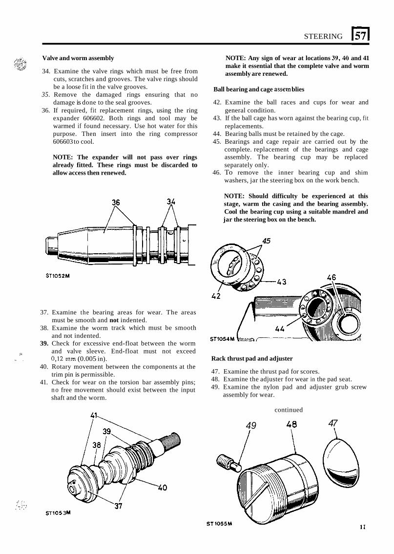
Valve and worm assembly
34. Examine the valve rings which must be free from cuts, scratches and grooves. The valve rings should be a loose fit in the valve grooves.
35. Remove the damaged rings ensuring that no damage is done to the seal grooves.
36. If required, fit replacement rings, using the ring expander 606602. Both rings and tool may be warmed if found necessary. Use hot water for this purpose. Then insert into the ring compressor 606603 to cool.
NOTE: Any sign of wear at locations 39,40 and 41 make it essential that the complete valve and worm assembly are renewed.
Ball bearing and cage assem blies
42. Examine the ball races and cups for wear and
43. If the ball cage has worn against the bearing cup, fit
44. Bearing balls must be retained by the cage. 45. Bearings and cage repair are carried out by the
complete. replacement of the bearings and cage assembly. The bearing cup may be replaced separately only.
46. To remove the inner bearing cup and shim washers, jar the steering box on the work bench.
general condition.
replacements.
NOTE: The expander will not pass over rings already fitted. These rings must be discarded to allow access then renewed.
NOTE: Should difficulty be experienced at this stage, warm the casing and the bearing assembly. Cool the bearing cup using a suitable mandrel and jar the steering box on the bench.
ST1052M
37. Examine the bearing areas for wear. The areas must be smooth and not indented.
38. Examine the worm track which must be smooth and not indented.
39. Check for excessive end-float between the worm and valve sleeve. End-float must not exceed 0,12 mm (0.005 in).
40. Rotary movement between the components at the trim pin is permissible.
41. Check for wear on the torsion bar assembly pins; n o free movement should exist between the input shaft and the worm.
J I ST10 5 3 M
45
Rack thrust pad and adjuster
47. Examine the thrust pad for scores. 48. Examine the adjuster for wear in the pad seat. 49. Examine the nylon pad and adjuster grub screw
assembly for wear.
49 I
continued
40 \
47 \
1571 STEERING
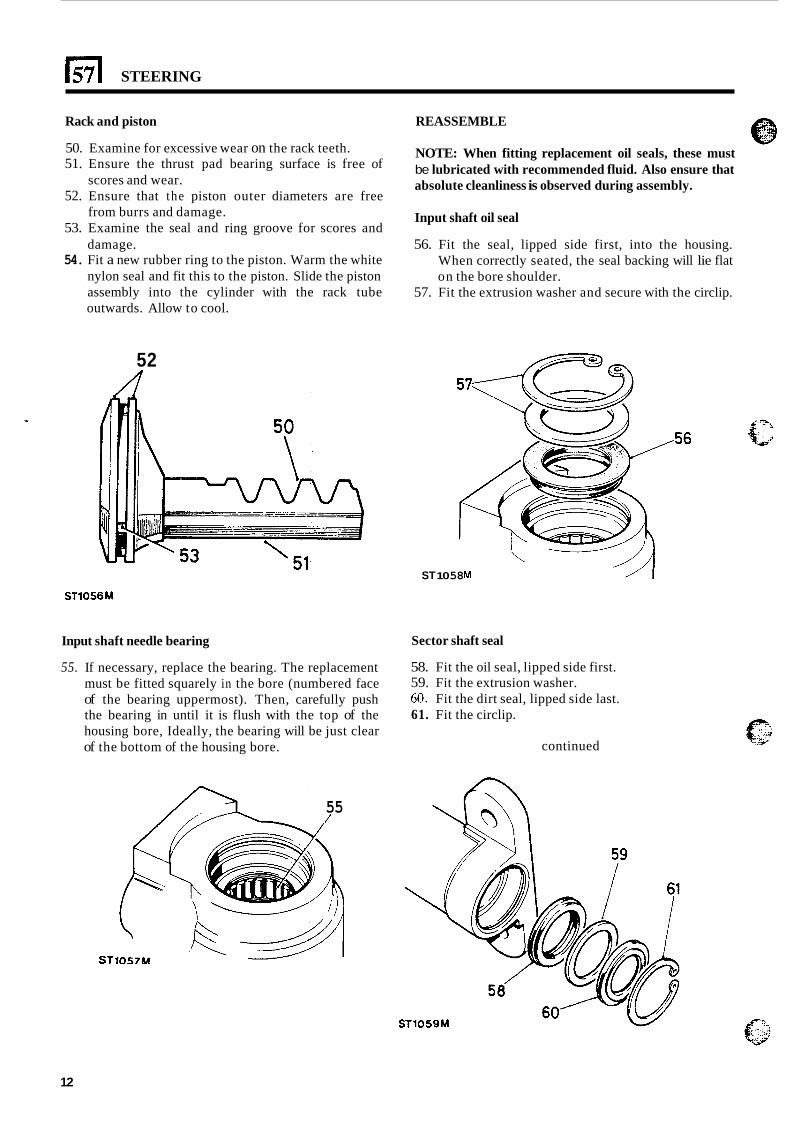
Rack and piston
50. Examine for excessive wear on the rack teeth. 51. Ensure the thrust pad bearing surface is free of
scores and wear. 52. Ensure that the piston outer diameters are free
from burrs and damage. 53. Examine the seal and ring groove for scores and
damage. 54. Fit a new rubber ring to the piston. Warm the white
nylon seal and fit this to the piston. Slide the piston assembly into the cylinder with the rack tube outwards. Allow to cool.
REASSEMBLE
52
NOTE: When fitting replacement oil seals, these must be lubricated with recommended fluid. Also ensure that absolute cleanliness is observed during assembly.
Input shaft oil seal
56. Fit the seal, lipped side first, into the housing. When correctly seated, the seal backing will lie flat on the bore shoulder.
57. Fit the extrusion washer and secure with the circlip.
ST 10 58 M / I ST1056M
Input shaft needle bearing
55. If necessary, replace the bearing. The replacement must be fitted squarely in the bore (numbered face of the bearing uppermost). Then, carefully push the bearing in until it is flush with the top of the housing bore, Ideally, the bearing will be just clear of the bottom of the housing bore.
Sector shaft seal
58. Fit the oil seal, lipped side first. 59. Fit the extrusion washer. 60. Fit the dirt seal, lipped side last. 61. Fit the circlip.
continued
55 /
12
STEERING
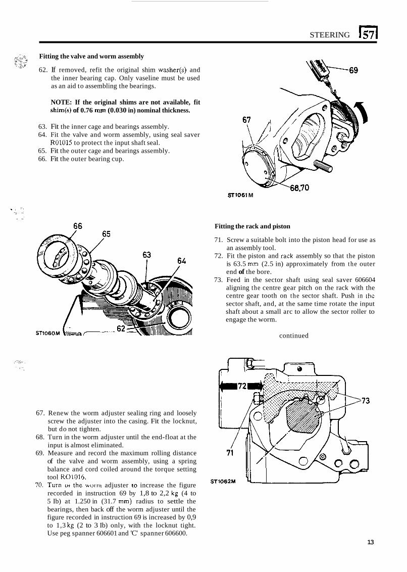
Fitting the valve and worm assembly
62. If removed, refit the original shim washer(s) and the inner bearing cap. Only vaseline must be used as an aid to assembling the bearings.
NOTE: If the original shims are not available, fit shim(s) of 0.76 mm (0.030 in) nominal thickness.
63. Fit the inner cage and bearings assembly. 64. Fit the valve and worm assembly, using seal saver
R01015 to protect the input shaft seal. 65. Fit the outer cage and bearings assembly. 66. Fit the outer bearing cup.
SrlOSl M
Fitting the rack and piston
71. Screw a suitable bolt into the piston head for use as an assembly tool.
72. Fit the piston and rack assembly so that the piston is 63.5 mm (2.5 in) approximately from the outer end of the bore.
73. Feed in the sector shaft using seal saver 606604 aligning the centre gear pitch on the rack with the centre gear tooth on the sector shaft. Push in the sector shaft, and, at the same time rotate the input shaft about a small arc to allow the sector roller to engage the worm.
continued
67. Renew the worm adjuster sealing ring and loosely screw the adjuster into the casing. Fit the locknut, but do not tighten.
68. Turn in the worm adjuster until the end-float at the input is almost eliminated.
69. Measure and record the maximum rolling distance of the valve and worm assembly, using a spring balance and cord coiled around the torque setting tool R01016.
70. I----- I U I I I I I I .- the worm adjuster to increase the figure recorded in instruction 69 by 1,8 to 2,2 kg (4 to 5 Ib) at 1.250 in (31.7 mm) radius to settle the bearings, then back off the worm adjuster until the figure recorded in instruction 69 is increased by 0,9 to 1,3 kg (2 to 3 Ib) only, with the locknut tight. Use peg spanner 606601 and 'C' spanner 606600.
13
STEERING
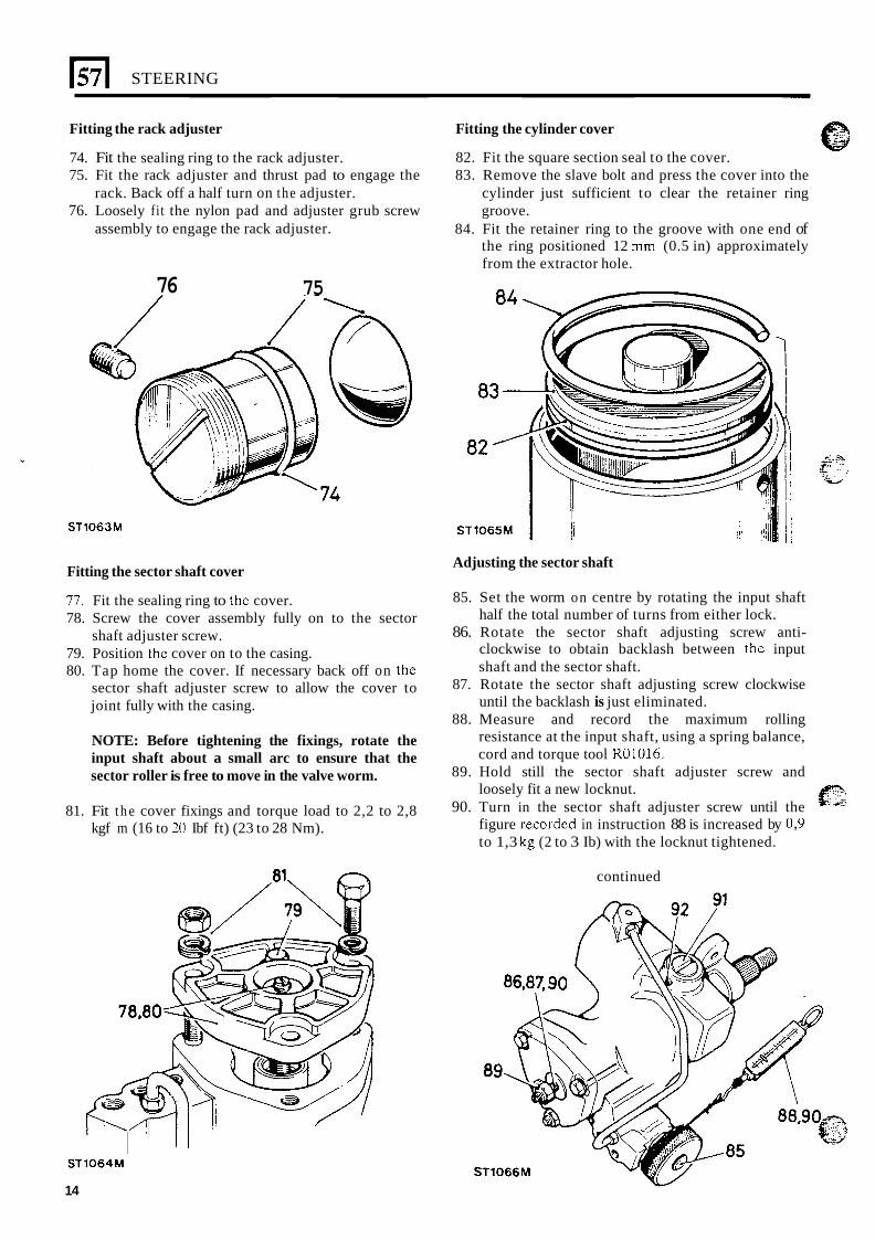
Fitting the rack adjuster
74. Fit the sealing ring to the rack adjuster. 75. Fit the rack adjuster and thrust pad to engage the
76. Loosely fit the nylon pad and adjuster grub screw
Fitting the cylinder cover
82. Fit the square section seal to the cover. 83. Remove the slave bolt and press the cover into the
cylinder just sufficient to clear the retainer ring groove.
84. Fit the retainer ring to the groove with one end of the ring positioned 12 mm (0.5 in) approximately from the extractor hole.
rack. Back off a half turn on the adjuster.
assembly to engage the rack adjuster.
76 75
ST1063M
Fitting the sector shaft cover
77. Fit the sealing ring to the cover. 78. Screw the cover assembly fully on to the sector
79. Position the cover on to the casing. 80. Tap home the cover. If necessary back off on the
sector shaft adjuster screw to allow the cover to joint fully with the casing.
shaft adjuster screw.
NOTE: Before tightening the fixings, rotate the input shaft about a small arc to ensure that the sector roller is free to move in the valve worm.
81. Fit t h e cover fixings and torque load to 2,2 to 2,8 kgf m (16 to 20 Ibf ft) (23 to 28 Nm).
Adjusting the sector shaft
85. Set the worm on centre by rotating the input shaft half the total number of turns from either lock.
86. Rotate the sector shaft adjusting screw anti- clockwise to obtain backlash between the input shaft and the sector shaft.
87. Rotate the sector shaft adjusting screw clockwise until the backlash is just eliminated.
88. Measure and record the maximum rolling resistance at the input shaft, using a spring balance, cord and torque tool R01016.
89. Hold still the sector shaft adjuster screw and loosely fit a new locknut.
90. Turn in the sector shaft adjuster screw until the figure recordcd in instruction 88 is increased by 0,9 to 1,3 kg (2 to 3 Ib) with the locknut tightened.
f". 't. d
continued
ST1064M
14
STEERING El e','t:i:t Adjusting the rack adjuster
91. Turn in the rack adjuster to increase the figure recorded in 90 by 0,9 to 1,3 kg (2 to 3 lb). The final figure may be less than but must not exceed 7,25 kg (16 Ib).
92. Lock the rack adjuster in position with the grub screw.
Adjustments
95. Note where the greatest figures are recorded relative to the steering gear position. If the greatest figures are not recorded across the centre of travel (i.e. steering straight ahead position), adjust as follows: L.H. steering models. If the torque peak occurs
before the centre position, add to the shim washer valve; if the torque peak occurs after the centre position, subtract from the shim washer valve.
R.H. steering models. If the torque peak occurs before the centre position, subtract from the shim washer valve; if the torque occurs after the centre position, add to the shim washer valve.
Shim washers are available as follows: 0,03 mm, 0,07 mm, 0,12 mm and 0,24 mm (0.0015 in, 0.003 in, 0.005 in and 0.010 in).
Torque peak check
With the input shaft rotated from lock-to-lock, the rolling resistance torque figures should be greatest across the centre position (1% turns approximately from full lock) and equally disposed about the centre position. This condition depends on the value of shimming fitted between the valve and worm assembly inner bearing cup and the casing. The original shim washer value will give the correct torque peak position unless major components have been replaced.
NOTE: During the following 'Procedure', the stated positioning and direction of the input shaft applies for both L.H. and R.H. boxes. However, the procedure for shim adjustment where necessary, differs between L.H. and R.H. steering boxes and is described under the applicable L.H. stg. and R.H. stg. headings.
-
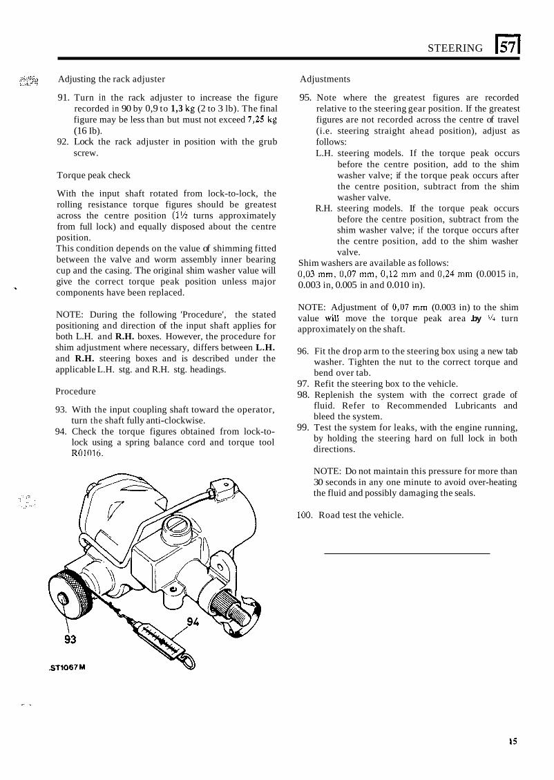
Procedure
93. With the input coupling shaft toward the operator, turn the shaft fully anti-clockwise.
94. Check the torque figures obtained from lock-to- lock using a spring balance cord and torque tool R01016.
NOTE: Adjustment of 0,07 mm (0.003 in) to the shim value will move the torque peak area .by 9'' turn approximately on the shaft.
96. Fit the drop arm to the steering box using a new tab washer. Tighten the nut to the correct torque and bend over tab.
97. Refit the steering box to the vehicle. 98. Replenish the system with the correct grade of
fluid. Refer to Recommended Lubricants and bleed the system.
99. Test the system for leaks, with the engine running, by holding the steering hard on full lock in both directions.
NOTE: Do not maintain this pressure for more than 30 seconds in any one minute to avoid over-heating the fluid and possibly damaging the seals.
100. Road test the vehicle.
. .
171 STEERING
BLEEDING THE POWER STEERING SYSTEM TEST POWER STEERING SYSTEM
Service tools: Three-way adaptor - JD10-2/1 Gauge - JDlO Hose - JD 10-3 2-off Hose - JDIO-3A Adaptor - JD10-6/1 Adaptor - JD10-6/2
If there is a lack of power assistance for the steering the pressure of the hydraulic pump should be checked first before renewing any components of the system. The fault diagnosis chart should also be used to assist in tracing faults in the power steering.
PROCEDURE
1. The hydraulic pressure test gauge is used in conjunction with the special adaptor (as illustrated) for testing the power steering system. This gauge is calibrated to read up to 140 kgf/cm’ (2000 Ibf/in2)
in the power steering system is 60 kgf/cm2 (850 Ibf/in2j.
2. Under certain fault conditions of the hydraulic pump it is possible to obtain pressures up to 105 kgf/cm2 (1500 lbf/in2). Therefore, it is important to realise that the pressure upon the gauge is in direct proportion to the pressure being exerted upon the steering wheel. When testing, apply pressure to the steering wheel very gradually while carefully observing the pressure gauge.
3 . Check, and if necessary replenish, the fluid reservoir.
4. Examine the power steering units and connections for leaks. All leaks must be rectified before attempting to test the system.
5. Check the steering pump drive belt for condition and tension, rectify as neccssary. The pump used on the V8 engined vehicle is different from that fitted to the four cylinder T-r engined vehicles but the test figures are the same for both pumps, Diagrams show how the test equipment is assembled for both vehicles.
6. Assemble the test equipment in accordance with the diagram for the vehicle concerned.
7. Open the tap in the adaptor JD10-211. 8. Bleed the system but exercise extreme care when
carrying out this operation so as not to overload the pressure gauge.
9. With the system in good condition, the pressures should be as follows: (a) Steering wheel held hard on full lock and
engine running at 1,000 rev/min, the pressure shouici be 60 to 67 i<gf/cm2 (850 to 950 ibf/in2j.
(b) With the engine idling and the steering wheel held hard on full lock, the pressure should be 28 kgf/cm2 (400 lbf/in2) minimum.
-. and the normal pressure which may be expected 3.- _I
continued
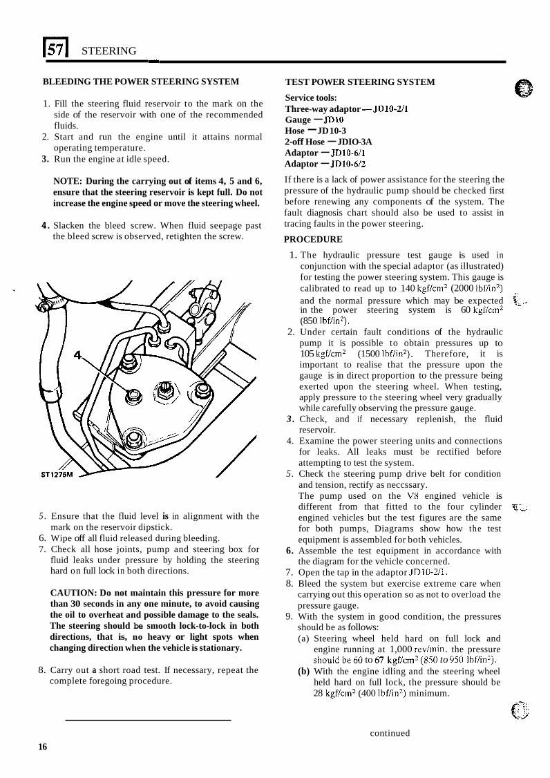
1. Fill the steering fluid reservoir to the mark on the side of the reservoir with one of the recommended fluids.
2. Start and run the engine until it attains normal operating temperature.
3. Run the engine at idle speed.
NOTE: During the carrying out of items 4, 5 and 6, ensure that the steering reservoir is kept full. Do not increase the engine speed or move the steering wheel.
4. Slacken the bleed screw. When fluid seepage past the bleed screw is observed, retighten the screw.
5 . Ensure that the fluid level is in alignment with the
6. Wipe off all fluid released during bleeding. 7. Check all hose joints, pump and steering box for
fluid leaks under pressure by holding the steering hard on full lock in both directions.
mark on the reservoir dipstick.
CAUTION: Do not maintain this pressure for more than 30 seconds in any one minute, to avoid causing the oil to overheat and possible damage to the seals. The steering should be smooth lock-to-lock in both directions, that is, no heavy or light spots when changing direction when the vehicle is stationary.
8. Carry out a short road test. If necessary, repeat the complete foregoing procedure.
16
STEERING
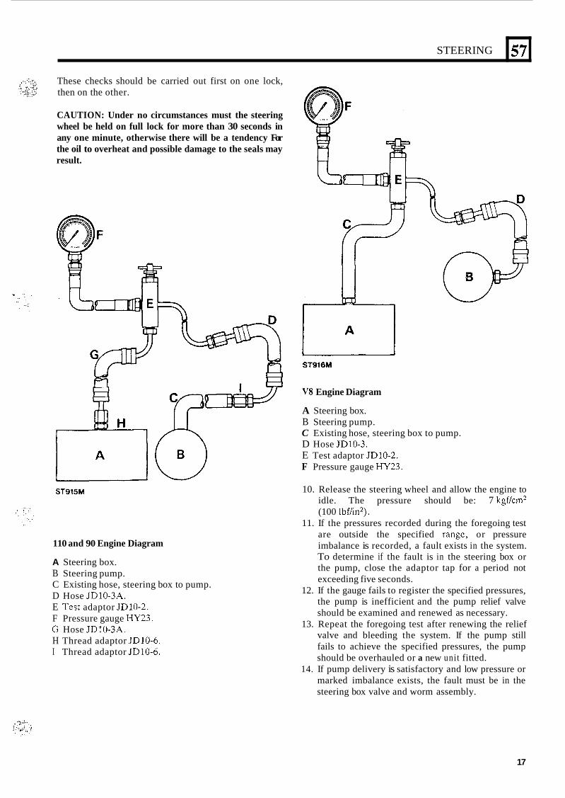
These checks should be carried out first on one lock, then on the other.
57
CAUTION: Under no circumstances must the steering wheel be held on full lock for more than 30 seconds in any one minute, otherwise there will be a tendency For the oil to overheat and possible damage to the seals may result.
L U ST915M
110 and 90 Engine Diagram
A Steering box. B Steering pump. C Existing hose, steering box to pump. D Hose JD10-3A. E Test adaptor JD10-2. F Pressure gauge HY23. G Hose JDIO-3A. H Thread adaptor JDlO-6. I Thread adaptor JDlO-6.
ST916M
V8 Engine Diagram
A Steering box. B Steering pump. C Existing hose, steering box to pump. D Hose JD10-3. E Test adaptor JD10-2. F Pressure gauge HY23.
10. Release the steering wheel and allow the engine to idle. The pressure should be: 7 kgfkm’ (100 Ibf/in2).
11. If the pressures recorded during the foregoing test are outside the specified rangc, or pressure imbalance is recorded, a fault exists in the system. To determine if the fault is in the steering box or the pump, close the adaptor tap for a period not exceeding five seconds.
12. If the gauge fails to register the specified pressures, the pump is inefficient and the pump relief valve should be examined and renewed as necessary.
13. Repeat the foregoing test after renewing the relief valve and bleeding the system. If the pump still fails to achieve the specified pressures, the pump should be overhauled or a new uni t fitted.
14. If pump delivery is satisfactory and low pressure or marked imbalance exists, the fault must be in the steering box valve and worm assembly.
17
57
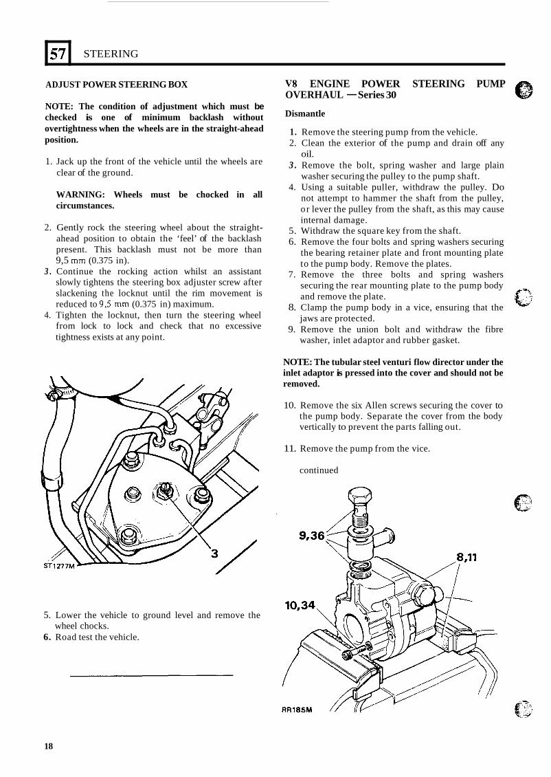
AD JUST POWER STEERING BOX
STEERING
NOTE: The condition of adjustment which must be checked is one of minimum backlash without overtightness when the wheels are in the straight-ahead position.
1. Jack up the front of the vehicle until the wheels are clear of the ground.
WARNING: Wheels must be chocked in all circumstances.
2. Gently rock the steering wheel about the straight- ahead position to obtain the ‘feel’ of the backlash present. This backlash must not be more than 9,5 mm (0.375 in).
3 . Continue the rocking action whilst an assistant slowly tightens the steering box adjuster screw after slackening the locknut until the rim movement is reduced to 9,5 mm (0.375 in) maximum.
4. Tighten the locknut, then turn the steering wheel from lock to lock and check that no excessive tightness exists at any point.
5. Lower the vehicle to ground level and remove the
6. Road test the vehicle. wheel chocks.
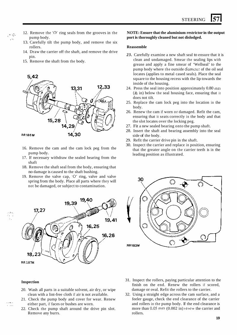
V8 ENGINE POWER STEERING PUMP OVERHAUL - Series 30
Dismantle
1. Remove the steering pump from the vehicle. 2. Clean the exterior of the pump and drain off any
oil. 3 . Remove the bolt, spring washer and large plain
washer securing the pulley to the pump shaft. 4. Using a suitable puller, withdraw the pulley. Do
not attempt to hammer the shaft from the pulley, or lever the pulley from the shaft, as this may cause internal damage.
5. Withdraw the square key from the shaft. 6. Remove the four bolts and spring washers securing
the bearing retainer plate and front mounting plate to the pump body. Remove the plates.
7. Remove the three bolts and spring washers securing the rear mounting plate to the pump body and remove the plate.
8. Clamp the pump body in a vice, ensuring that the jaws are protected.
9. Remove the union bolt and withdraw the fibre washer, inlet adaptor and rubber gasket.
NOTE: The tubular steel venturi flow director under the inlet adaptor is pressed into the cover and should not be removed.
10. Remove the six Allen screws securing the cover to the pump body. Separate the cover from the body vertically to prevent the parts falling out.
11. Remove the pump from the vice.
continued
18
STEERING 15711 .. 12. Remove the ‘0’ ring seals from the grooves in the
13. Carefully tilt the pump body, and remove the six
14. Draw the carrier off the shaft, and remove the drive
15. Remove the shaft from the body.
“ .- * I . 1 pump body.
rollers.
pin.
c ”-
5,42
. ,., . . . . . ....
15,28
13fl 12,33 //
RR186M 14,30
16. Remove the cam and the cam lock peg from the pump body.
17. If necessary withdraw the sealed bearing from the shaft
18. Remove the shaft seal from the body, ensuring that no damage is caused to the shaft bushing.
19. Remove the valve cap, ‘0’ ring, valve and valve spring from the body. Place all parts where they will not be damaged, or subject to contamination.
RR 187M
NOTE: Ensure that the aluminium restrictor in the output port is thoroughly cleaned but not dislodged.
Reassemble
23. Carefully examine a new shaft seal to ensure that it is clean and undamaged. Smear the sealing lips with grease and apply a fine smear of ‘Wellseal’ to the pump body where the outside diamcter of the oil seal locates (applies to metal cased seals). Place the seal square to the housing recess with the lip towards the inside of the housing.
24. Press the seal into position approximately 0.80 mm (& in) below the seal housing face, ensuring that i t does not tilt.
25. Replace the cam lock peg into the location in the body.
26. Renew the cam if worn or damaged. Refit the cam, ensuring that it seats correctly in the body and that the slot locates over the locking peg.
27. Fit a new sealed bearing onto the pump shaft. 28. Insert the shaft and bearing assembly into the seal
29. Refit the carrier drive pin in the shaft. 30. Inspect the carrier and replace in position, ensuring
that the greater angle on the carrier teeth is in the leading position as illustrated.
side of the body.
Y 3
RR183M
Inspection
20. Wash all parts in a suitable solvent, air dry, or wipe clean with a lint-free cloth if air is not available.
21. Check the pump body and cover for wear. Renew either part, i f faces or bushes are worn.
22. Check the pump shaft around the drive pin slot. Remove any burrs. rollers.
31. Inspect the rollers, paying particular attention to the finish on the end. Renew the rollers i f scored, damage or oval. Refit the rollers to the carrier.
32. Using a straight edge across the cam surface, and a feeler gauge, check the end clearance of the carrier and rollers in the pump body. If the end clearance is more than 0,05 mm (0.002 in) rencw the carrier and
19
STEERING
32 \\-
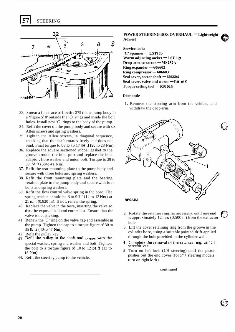
6 a $ POWER STEERING BOX OVERHAUL - Lightweight Adwest
Service tools: ‘C’ Spanner - LST120 Worm adjusting socket - LST119 Drop arm extractor - MS252A Ring expander - 606602 Ring compressor - 606603 Seal saver, sector shaft - 606604 Seal saver, valve and worm - R01015 Torque setting tool - R01016
Dismantle
1 . Remove the steering arm from the vehicle, and withdraw the drop arm.
33. Smear a fine trace of Loctite 275 to the pump body in a ‘figure of 8’ outside the ‘0’ rings and inside the bolt holes. Install new ‘0’ rings to the body of the pump.
34. Refit the cover on the pump body and secure with six Allen screws and spring washers.
35. Tighten the Allen screws, in diagonal sequence, checking that the shaft rotates freely and does not bind. Final torque to be 15 to 17 Ibf.ft (20 to 23 Nm).
36. Replace the square sectioned rubber gasket to the groove around the inlet port and replace the inlet adaptor, fibre washer and union bolt. Torque to 28 to 30 1bf.ft (38 to 41 Nm).
secure with three bolts and spring washers.
retainer plate to the pump body and secure with four bolts and spring washers.
39. Refit the flow control valve spring in the bore. The spring tension should be 8 to 9 Ibf (11 to 12 Nm) at 21 mm (0.820 in). If not, renew the spring.
40. Replace the valve in the bore, inserting the valve so
37. Refit the rear mounting plate to the pump body and
38. Refit the front mounting plate and the bearing
RR923M
43.
44.
f?“ tha; the exposed ball end enters last. Ensure that the valve is not sticking.
41. Renew the ‘0’ ring on the valve cap and assemble in the pump. Tighten the cap to a torque figure of 30 to 35 Ib.ft (40 to 47 Nm).
2. Rotate the retainer ring, as necessary, until one end is approximately 12 mm (0.500 in) from the extractor . e r
hole. 3. Lift the cover retaining ring from the groove in the
cylinder bore, using a suitable pointed drift applied through the hole provided in the cylinder wall.
screwdriver.
42. Refit the pulley key. ’ Refit the pulley to the shaft and with the 4. Complete the removal of the retainer ring, using a special washer, spring and washer and bolt. Tighten
the bolt to a torque figure of 10 to 12 Ibf.ft (13 to 5 . Turn on left lock (LH steering) until the piston ,L ’ * T A _ \ 10 i u m i . Refit the steering pump to the vehicle. pushes out the end cover (for R H steering models,
turn on right lock).
continued
20
STEERING
1 . ’.
57
5-K lll \
. RR1695M w
6. Slacken the grub screw retaining the rack pad
7. Remove the rack pad adjuster. 8. Remove the sector shaft adjuster locknut. 9. Remove the sector shaft cover fixings.
adjuster.
10. Screw in the sector shaft adjuster until the cover is
11. Slide out the sector shaft. removed.
1
RR924M
15. Tap the splined end of the spindle shaft to free the
16. Withdraw the bearing cup and cagcd ball bearing bearing.
assembly.
l6 17 \ A
17. Withdraw the valve and worm assembly. 18. Withdraw the inner bearing ball race and shims.
Retain the shims.
continued
12. Withdraw the piston, using a suitable bolt screwed
13. Remove the worm adjuster locknut using ‘C’
14. Remove the worm adjuster using socket LSTl19.
into the tapped hole in the piston.
spanner, LST120.
‘I . . ; ,
21
157 I STEERING
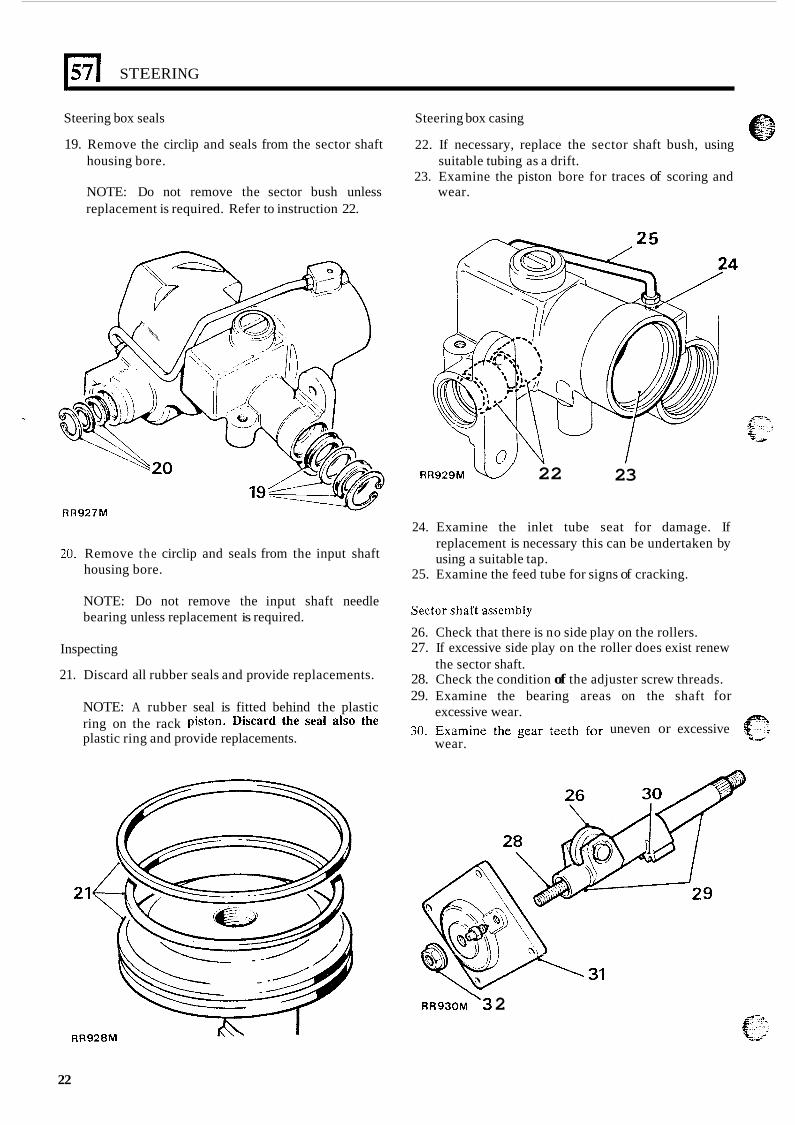
Steering box seals
19. Remove the circlip and seals from the sector shaft
Steering box casing
22. If necessary, replace the sector shaft bush, using
23. Examine the piston bore for traces of scoring and housing bore.
NOTE: Do not remove the sector bush unless wear. replacement is required. Refer to instruction 22.
suitable tubing as a drift.
20. Remove the circlip and seals from the input shaft housing bore.
RR929M v/ 22 23
24. Examine the inlet tube seat for damage. If replacement is necessary this can be undertaken by using a suitable tap.
25. Examine the feed tube for signs of cracking.
NOTE: Do not remove the input shaft needle bearing unless replacement is required.
Sectorshaftassembly
26. Check that there is no side play on the rollers. 27. If excessive side play on the roller does exist renew
28. Check the condition of the adjuster screw threads. 29. Examine the bearing areas on the shaft for
30. Examine the gear teeth for uneven or excessive
Inspecting
21. Discard all rubber seals and provide replacements. the sector shaft.
excessive wear.
wear.
NOTE: A rubber seal is fitted behind the plastic ring on the rack Piston- Discard the sea1 also the plastic ring and provide replacements.
RR928M
22
RR930M ‘3 2
STEERING
/ - .: ,,;...-, .: . .. _.. Sector shaft cover assembly ,..& . ..__., ....,_ . ,..,. =: ... 'i..Y., ..'?
31. The cover, bush and seat are supplied as a U..
complete assembly for replacement purposes.
L
57
Sector shaft adjuster locknut
32. The locknut functions also as a fluid seal and must be replaced at overhaul.
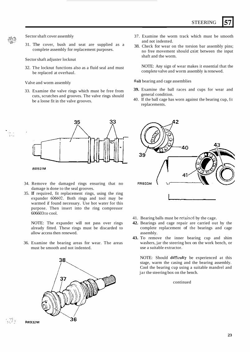
Valve and worm assembly
33. Examine the valve rings which must be free from cuts, scratches and grooves. The valve rings should be a loose fit in the valve grooves.
* - . . . .. . . . . .. I .
RR931M
34. Remove the damaged rings ensuring that no damage is done to the seal grooves.
35. If required, fit replacement rings, using the ring expander 606602. Both rings and tool may be warmed if found necessary. Use hot water for this purpose. Then insert into the ring compressor 606603 to cool.
NOTE: The expander will not pass over rings already fitted. These rings must be discarded to allow access then renewed.
36. Examine the bearing areas for wear. The areas must be smooth and not indented.
37. Examine the worm track which must be smooth and not indented.
38. Check for wear on the torsion bar assembly pins; no free movement should cxist between the input shaft and the worm.
NOTE: Any sign of wear makes it essential that the complete valve and worm assembly is renewed.
Ball bearing and cage assemblies
39. Examine the ball races and cups for wear and
40. If the ball cage has worn against the bearing cup, fit general condition.
replacements.
41. Bearing balls must be retained by the cage. 42. Bearings and cage repair are carried out by the
complete replacement of the bearings and cage assembly.
43. To remove the inner bearing cup and shim washers, jar the steering box on the work bench, or use a suitable extractor.
NOTE: Should dificulty be experienced at this stage, warm the casing and the bearing assembly. Cool the bearing cup using a suitable mandrel and ja r the steering box on the bench.
continued
'36
23
571 STEERING
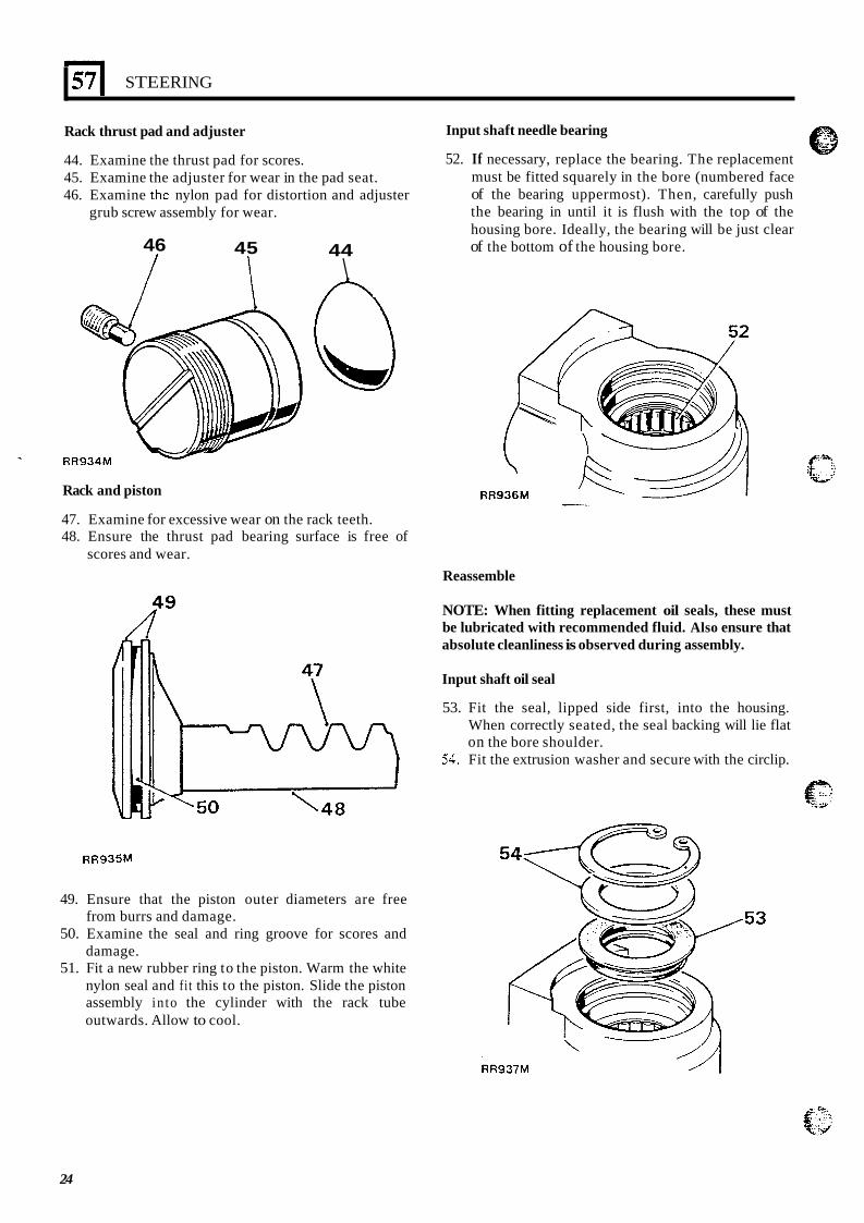
Rack thrust pad and adjuster
44. Examine the thrust pad for scores. 45. Examine the adjuster for wear in the pad seat. 46. Examine the nylon pad for distortion and adjuster
grub screw assembly for wear.
46 I I
45 I I
44 \ A
1 W R R 9 3 4 M
Rack and piston
47. Examine for excessive wear on the rack teeth. 48. Ensure the thrust pad bearing surface is free of
scores and wear.
R"
Input shaft needle bearing
52. If necessary, replace the bearing. The replacement must be fitted squarely in the bore (numbered face of the bearing uppermost). Then, carefully push the bearing in until it is flush with the top of the housing bore. Ideally, the bearing will be just clear of the bottom of the housing bore.
RR936M
Reassemble
NOTE: When fitting replacement oil seals, these must be lubricated with recommended fluid. Also ensure that absolute cleanliness is observed during assembly.
Input shaft oil seal
53. Fit the seal, lipped side first, into the housing. When correctly seated, the seal backing will lie flat on the bore shoulder.
54. Fit the extrusion washer and secure with the circlip.
R R 9 3 5 M
49. Ensure that the piston outer diameters are free from burrs and damage.
50. Examine the seal and ring groove for scores and damage.
51. Fit a new rubber ring to the piston. Warm the white nylon seal and fi t this to the piston. Slide the piston assembly in to the cylinder with the rack tube outwards. Allow to cool.
24
STEERING
Sector shaft seal
57
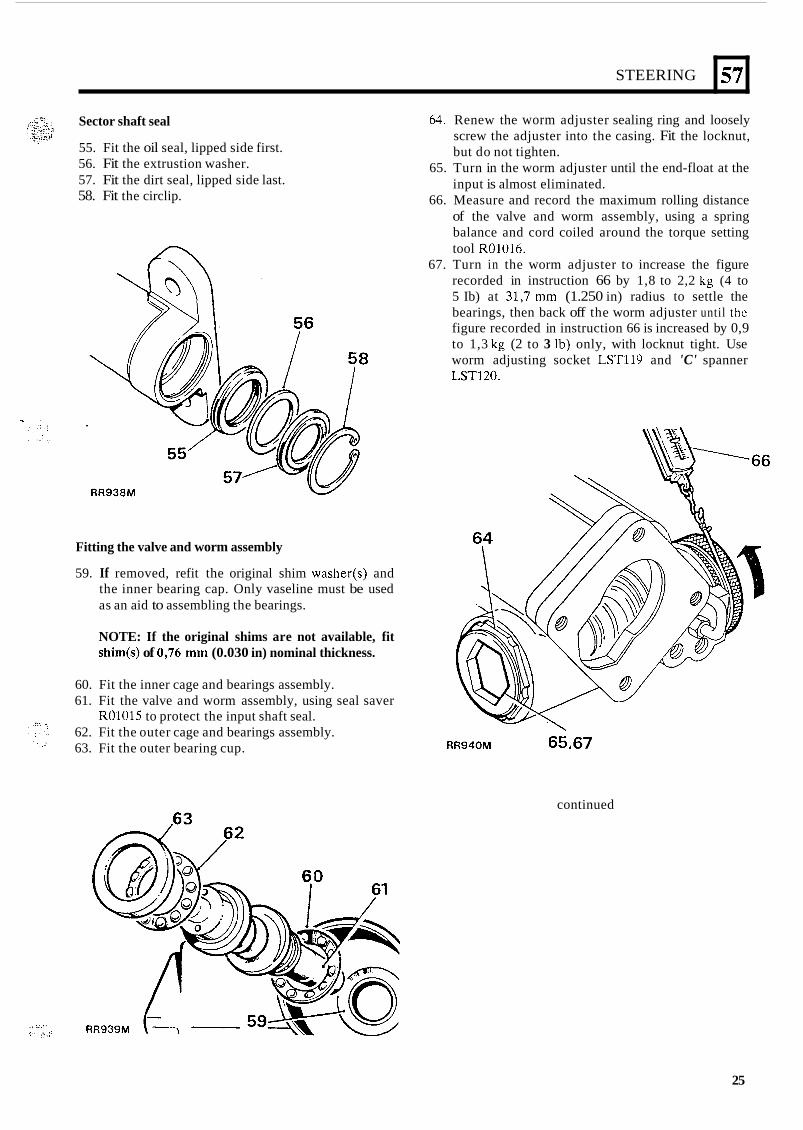
55. Fit the oil seal, lipped side first. 56. Fit the extrustion washer. 57. Fit the dirt seal, lipped side last. 58. Fit the circlip.
Fitting the valve and worm assembly
59. If removed, refit the original shim washer(s) and the inner bearing cap. Only vaseline must be used as an aid to assembling the bearings.
NOTE: If the original shims are not available, fit shim(s) of 0,76 mm (0.030 in) nominal thickness.
, ...__ :>.,
.. ,.. <.' . .'
60. Fit the inner cage and bearings assembly. 61. Fit the valve and worm assembly, using seal saver
R01015 to protect the input shaft seal. 62. Fit the outer cage and bearings assembly. 63. Fit the outer bearing cup.
64. Renew the worm adjuster sealing ring and loosely screw the adjuster into the casing. Fit the locknut, but do not tighten.
65. Turn in the worm adjuster until the end-float at the input is almost eliminated.
66. Measure and record the maximum rolling distance of the valve and worm assembly, using a spring balance and cord coiled around the torque setting tool R01016.
67. Turn in the worm adjuster to increase the figure recorded in instruction 66 by 1,8 to 2,2 kg (4 to 5 Ib) at 31,7 mm (1.250 in) radius to settle the bearings, then back off the worm adjuster until the figure recorded in instruction 66 is increased by 0,9 to 1,3 kg (2 to 3 Ib) only, with locknut tight. Use worm adjusting socket LST119 and 'C' spanner LST120.
RR940M 65,67
continued
25
571 STEERING
Fitting the rack and piston
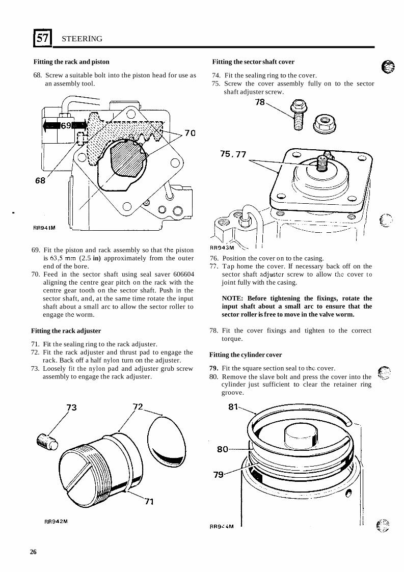
68. Screw a suitable bolt into the piston head for use as an assembly tool.
6
. RR941M I J
69. Fit the piston and rack assembly so that the piston is 63,5 mm (2.5 in) approximately from the outer end of the bore.
70. Feed in the sector shaft using seal saver 606604 aligning the centre gear pitch on the rack with the centre gear tooth on the sector shaft. Push in the sector shaft, and, at the same time rotate the input shaft about a small arc to allow the sector roller to engage the worm.
Fitting the rack adjuster
71. Fit the sealing ring to the rack adjuster. 72. Fit the rack adjuster and thrust pad to engage the
rack. Back off a half nylon turn on the adjuster. 73. Loosely fit the nylon pad and adjuster grub screw
assembly to engage the rack adjuster.
Fitting the sector shaft cover
74. Fit the sealing ring to the cover. 75. Screw the cover assembly fully on to the sector
shaft adjuster screw.
----- -
76. Position the cover on to the casing. 77. Tap home the cover. If necessary back off on the
sector shaft adjustcr screw to allow thc cover t o joint fully with the casing.
NOTE: Before tightening the fixings, rotate the input shaft about a small arc to ensure that the sector roller is free to move in the valve worm.
78. Fit the cover fixings and tighten to the correct torque.
Fitting the cylinder cover
79. Fit the square section seal to thc cover. 80. Remove the slave bolt and press the cover into the “j-;.
cylinder just sufficient to clear the retainer ring groove.
P:
RR942M
26
STEERING 1571 :-,
,. ,.Gz.::. ._,._ .* ,..z..y
81. Fit the retainer ring to the groove with one end of the ring positioned 12 mm (0.5 in) approximately from the extractor hole.
.. ./.>, . _. ....
Adjusting the sector shaft
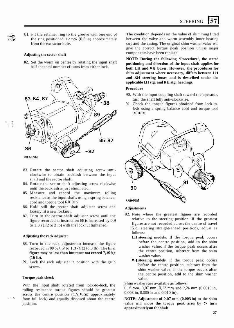
82. Set the worm on centre by rotating the input shaft half the total number of turns from either lock.
RR945M
83. Rotate the sector shaft adjusting screw anti- clockwise to obtain backlash between the input shaft and the sector shaft.
84. Rotate the sector shaft adjusting screw clockwise until the backlash is just eliminated.
85. Measure and record the maximum rolling resistance at the input shaft, using a spring balance, cord and torque tool R01016.
86. Hold still the sector shaft adjuster screw and loosely fit a new locknut.
87. Turn in the sector shaft adjuster screw until the figure recorded in instruction 88 is increased by 0,9 to 1,3 kg (2 to 3 Ib) with the locknut tightened.
Adjusting the rack adjuster
88. Turn in the rack adjuster to increase the figure recorded in 90 by 0,9 to 1,3 kg (2 to 3 Ib). The final figure may be less than but must not exceed 7,25 kg (16 Ib).
89. Lock the rack adjuster in position with the grub screw.
Torque peak check
With the input shaft rotated from lock-to-lock, the rolling resistance torque figures should be greatest across the centre position (1 Y2 turns approximately
position.
. . . . . .. . from full lock) and equally disposed about the centre
The condition depends on the value of shimming fitted between the valve and worm assembly inner bearing cup and the casing. The original shim washer value will give the correct torque peak position unless major components have been replace.
NOTE: During the following ‘Procedure’, the stated positioning and direction of the input shaft applies for both LH and RH boxes. However, the procedures for shim adjustment where necessary, differs between LH and RH steering boxes and is described under the applicable LH stg. and RH stg. headings.
Procedure 90. With the input coupling shaft toward the operator,
turn the shaft fully anti-clockwise. 91. Check the torque figures obtained from lock-to-
lock using a spring balance cord and torque tool R01016.
w RR946M
Adjustments 92. Note where the greatest figures are recorded
relative to the steering position. If the greatest figures are not recorded across the centre of travel (i.e. steering straight-ahead position), adjust as follows: LH steering models. If the torque peak occurs
before the centre position, add to the shim washer value; if the torque peak occurs after the centre position, subtract from the shim washer value.
RH steering models. If the torque peak occurs before the centre position, subtract from the shim washer value; if the torque occurs after the centre position, add to the shim washer value.
Shim washers are available as follows: 0,03 mm, 0,07 mm, 0,12 mm and 0,24 mm (0.0015 in, 0.003 in, 0.005 in and 0.010 in). NOTE: Adjustment of 0’07 mm (0.003 in) to the shim value will move the torque peak area by ‘/4 turn approximately on the shaft.
27
57
NOTE: Do not maintain this pressure for more than 30 seconds in any one minute to avoid overheating the fluid and possibly damaging the seals.
STEERING
97. Road test the vehicle.
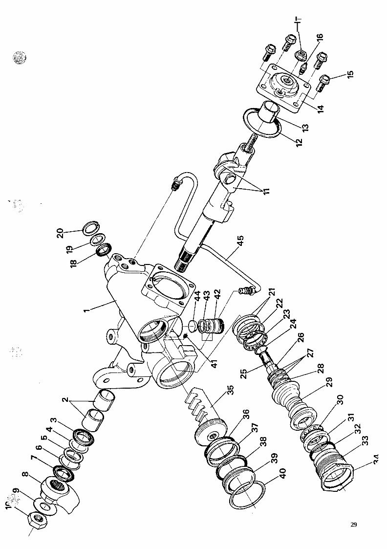
KEY TO ADWEST LIGHTWEIGHT POWER STEERING BOX
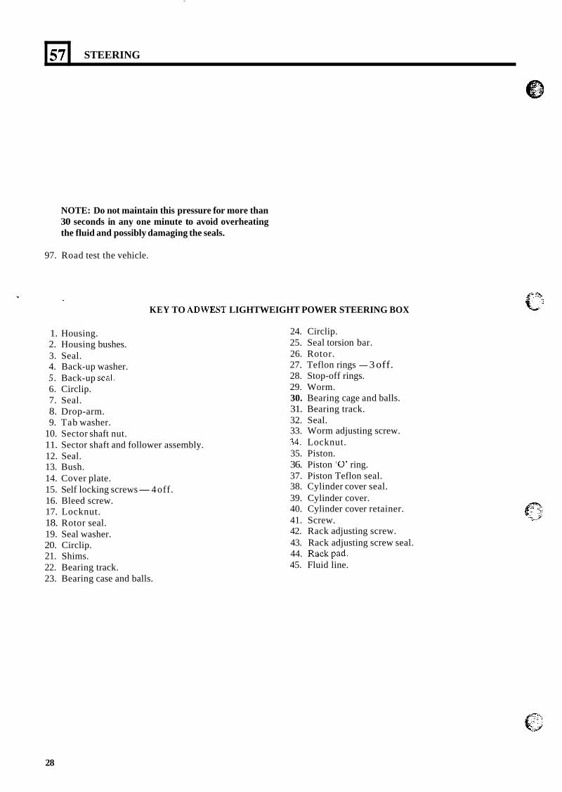
1. Housing. 2. Housing bushes. 3. Seal. 4. Back-up washer. 5 . Back-up seal. 6. Circlip. 7. Seal. 8. Drop-arm. 9. Tab washer.
10. Sector shaft nut. 11. Sector shaft and follower assembly. 12. Seal. 13. Bush. 14. Cover plate. 15. Self locking screws-4 off. 16. Bleed screw. 17. Locknut. 18. Rotor seal. 19. Seal washer. 20. Circlip. 21. Shims. 22. Bearing track. 23. Bearing case and balls.
24. Circlip. 25. Seal torsion bar. 26. Rotor. 27. Teflon rings - 3 off. 28. Stop-off rings. 29. Worm. 30. Bearing cage and balls. 31. Bearing track. 32. Seal. 33. Worm adjusting screw. 34. Locknut. 35. Piston. 36. Piston ‘0’ ring. 37. Piston Teflon seal. 38. Cylinder cover seal. 39. Cylinder cover. 40. Cylinder cover retainer. 41. Screw. 42. Rack adjusting screw. 43. Rack adjusting screw seal. 44. Rackpad. 45. Fluid line.
28
.. ..
. .. ... . . . . . I .. . . .
I-
T
29
171 STEERING
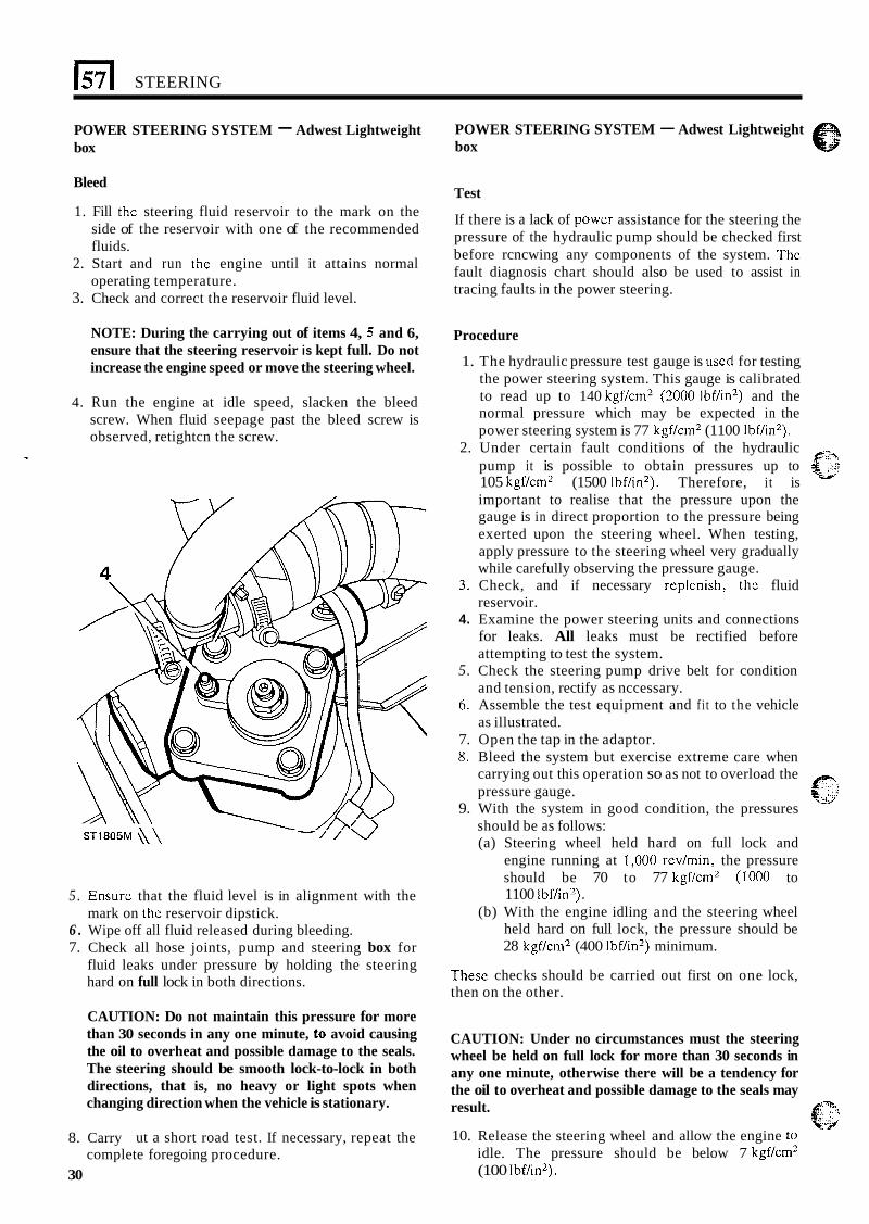
POWER STEERING SYSTEM - Adwest Lightweight box
Bleed
1. Fill thc steering fluid reservoir to the mark on the side of the reservoir with one of the recommended fluids.
2. Start and run the engine until it attains normal operating temperature.
3. Check and correct the reservoir fluid level.
NOTE: During the carrying out of items 4, 5 and 6, ensure that the steering reservoir is kept full. Do not increase the engine speed or move the steering wheel.
4. Run the engine at idle speed, slacken the bleed screw. When fluid seepage past the bleed screw is observed, retightcn the screw.
ST1805M \\\ - - I / v
5 . Ensure that the fluid level is in alignment with the
6 . Wipe off all fluid released during bleeding. 7. Check all hose joints, pump and steering box for
fluid leaks under pressure by holding the steering hard on full lock in both directions.
mark on thc reservoir dipstick.
CAUTION: Do not maintain this pressure for more than 30 seconds in any one minute, to avoid causing the oil to overheat and possible damage to the seals. The steering should be smooth lock-to-lock in both directions, that is, no heavy or light spots when changing direction when the vehicle is stationary.
8. Carry ut a short road test. If necessary, repeat the
30 complete foregoing procedure.
POWER STEERING SYSTEM - Adwest Lightweight box
Test
If there is a lack of powcr assistance for the steering the pressure of the hydraulic pump should be checked first before rcncwing any components of the system. The fault diagnosis chart should also be used to assist in tracing faults in the power steering.
Procedure
1. The hydraulic pressure test gauge is uscd for testing the power steering system. This gauge is calibrated to read up to 140 kgf/cm2 (2000 Ibf/in2) and the normal pressure which may be expected in the power steering system is 77 kgf/cm2 (1100 Ibf/in2).
2. Under certain fault conditions of the hydraulic F:h pump it is possible to obtain pressures up to g ;,::;
105 kgf/cm2 (1500 Ibf/in'). Therefore, it is important to realise that the pressure upon the gauge is in direct proportion to the pressure being exerted upon the steering wheel. When testing, apply pressure to the steering wheel very gradually while carefully observing the pressure gauge.
3. Check, and if necessary replcnish, thc fluid reservoir.
4. Examine the power steering units and connections for leaks. All leaks must be rectified before attempting to test the system.
5. Check the steering pump drive belt for condition and tension, rectify as nccessary.
6. Assemble the test equipment and f i t to the vehicle as illustrated.
7. Open the tap in the adaptor. 8. Bleed the system but exercise extreme care when
carrying out this operation so as not to overload the pressure gauge.
9. With the system in good condition, the pressures should be as follows: (a) Steering wheel held hard on full lock and
engine running at 1,000 rev/min, the pressure should be 70 to 77 kgf/cm2 (1000 to 1100 Ibf/in2).
(b) With the engine idling and the steering wheel held hard on full lock, the pressure should be 28 kgf/cm2 (400 Ibf/in2) minimum.
-4"
p: &. *,;:: .s
Thesc checks should be carried out first on one lock, then on the other.
CAUTION: Under no circumstances must the steering wheel be held on full lock for more than 30 seconds in any one minute, otherwise there will be a tendency for the oil to overheat and possible damage to the seals may result.
10. Release the steering wheel and allow the engine to idle. The pressure should be below 7 kgf/cm' (100 Ibf/in2).
.. .
STEERING 157
11. If the pressures recorded during the foregoing test are outside the specified range, or pressure imbalance is recorded, a fault exists in the system. To determine if the fault is in the steering box or the pump, close the adaptor tap for a period not exceeding five seconds.
12. If the gauge fails to register the specified pressures, the pump is inefficient and the pump relief valve should be examined and renewed as necessary.
13. Repeat the foregoing test after renewing the relief valve and bleeding the system. If the pump still fails to achieve the specified pressures, the pump should be overhauled or a new unit fitted.
14. If pump delivery is satisfactory and low pressure or marked imbalance exists, the fault must be in the steering box valve and worm assembly.
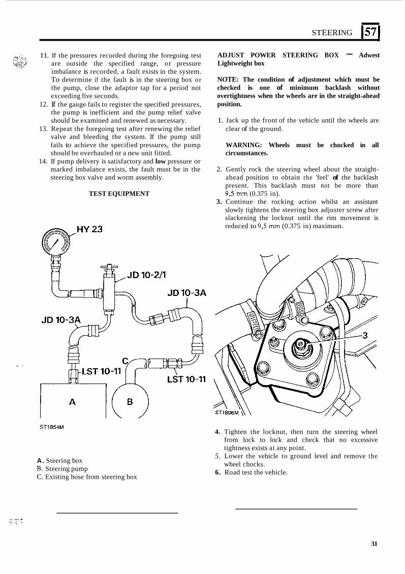
ADJUST POWER STEERING BOX - Adwest Lightweight box
NOTE: The condition of adjustment which must be checked is one of minimum backlash without overtightness when the wheels are in the straight-ahead position.
1. Jack up the front of the vehicle until the wheels are clear of the ground.
WARNING: Wheels must be chocked in all circumstances.
2. Gently rock the steering wheel about the straight- ahead position to obtain the 'feel' of the backlash present. This backlash must not be more than 9 3 mm (0.375 in).
3. Continue the rocking action whilst an assistant slowly tightens the steering box adjuster screw after slackening the locknut until the rim movement is reduced to 9,5 mm (0.375 in) maximum.
TEST EQUIPMENT
STl854M
A. Steering box B. Steering pump C. Existing hose from steering box
4. Tighten the locknut, then turn the steering wheel from lock to lock and check that no excessive tightness exists at any point.
5. Lower the vehicle to ground level and remove the wheel chocks.
6. Road test the vehicle.
.. ... . I . . . . . . .,. . l:: ::,.,. . .
31
STEERING
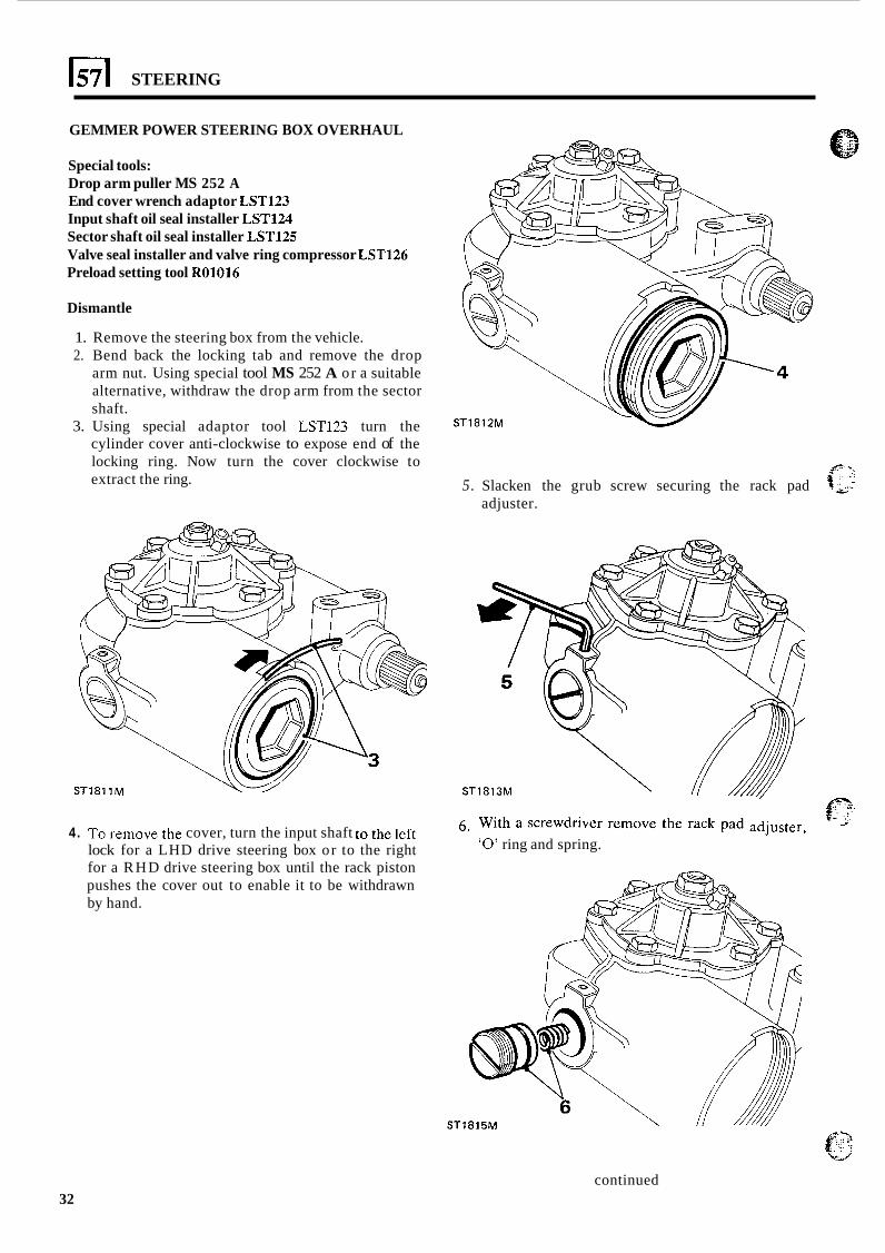
GEMMER POWER STEERING BOX OVERHAUL
Special tools: Drop arm puller MS 252 A End cover wrench adaptor LST123 Input shaft oil seal installer LST124 Sector shaft oil seal installer LST125 Valve seal installer and valve ring compressor LST126 Preload setting tool R01016
Dismantle
1. Remove the steering box from the vehicle. 2. Bend back the locking tab and remove the drop
arm nut. Using special tool MS 252 A or a suitable alternative, withdraw the drop arm from the sector shaft.
3. Using special adaptor tool LST123 turn the cylinder cover anti-clockwise to expose end of the locking ring. Now turn the cover clockwise to extract the ring. 5. Slacken the grub screw securing the rack pad
adjuster.
ST1811M ST1813M p * .
4. To remove the cover, turn the input shaft to the left lock for a LHD drive steering box or to the right for a RHD drive steering box until the rack piston pushes the cover out to enable it to be withdrawn by hand.
With a screwdriver remove the rack pad ‘0’ ring and spring.
ST1815M f?; c_/
continued 32
* . -> ,.. ,,.. ... . * c.;i:,.,] ,. . ... .. - ... . ..,.:e
STEERING 157
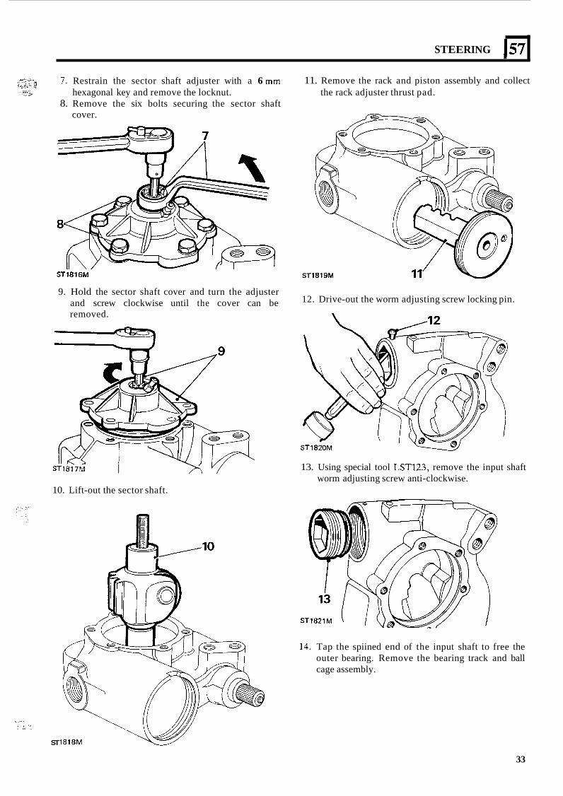
7 . Restrain the sector shaft adjuster with a 6 mm
8. Remove the six bolts securing the sector shaft hexagonal key and remove the locknut.
cover.
ST1816M
9. Hold the sector shaft cover and turn the adjuster and screw clockwise until the cover can be removed.
10. Lift-out the sector shaft.
. ,.I.. . .. .
ST
11. Remove the rack and piston assembly and collect the rack adjuster thrust pad.
ST '1819M
12. Drive-out the worm adjusting screw locking pin.
13. Using special tool LST123, remove the input shaft worm adjusting screw anti-clockwise.
14. Tap the spiined end of the input shaft to free the outer bearing. Remove the bearing track and ball cage assembly.
33
57
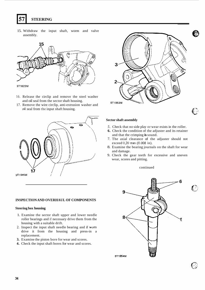
15. Withdraw the input shaft, worm and valve assembly.
STEERING
15
ST1822M
16. Release the circlip and remove the steel washer
17. Remove the wire circlip, anti-extrusion washer and and oil seal from the sector shaft housing.
Qil seal from the input shaft housing.
Sector shaft assembly
5. Check that no side play or wear exists in the roller. 6. Check the condition of the adjuster and its retainer
7. The axial clearance of the adjuster should not
8. Examine the bearing journals on the shaft for wear
9. Check the gear teeth for excessive and uneven
and that the crimping is sound.
exceed 0,20 mm (0.008 in).
and damage.
wear, scores and pitting.
continued
ST1949M I I
INSPECTION AND OVERHAUL OF COMPONENTS
Steering box housing
1. Examine the sector shaft upper and lower needle roller bearings and if necessary drive them from the housing with a suitable drift.
2. Inspect the input shaft needle bearing and if worn drive it from the housing and press-in a replacement.
3. Examine the piston bore for wear and scores. 4. Check the input shaft bores for wear and scores.
ST1954M
34
STEERING 157 I Valve and worm assembly
NOTE: If the inner ball race is faulty and unfit for further service it cannot be renewed and a new valve and worm assembly must be obtained and fitted. Should this be the case, the following checks of the valve and worm can be ignored.
10. Examine the valve rings which must be free from cuts, scratches and scores. Also, the rings should be a loose fit in the grooves.
11. If any ring is unsatisfactory, all the rings must be renewed. When removing the rings take care not to damage the valve grooves.
12. To fi t new rings use special tool LST126, which consists of the following three parts:-
a) Ring expander. b) Split collcr. c) Ring compressor.
Before using the tool lubricatc each part with the recommended power steering fluid.
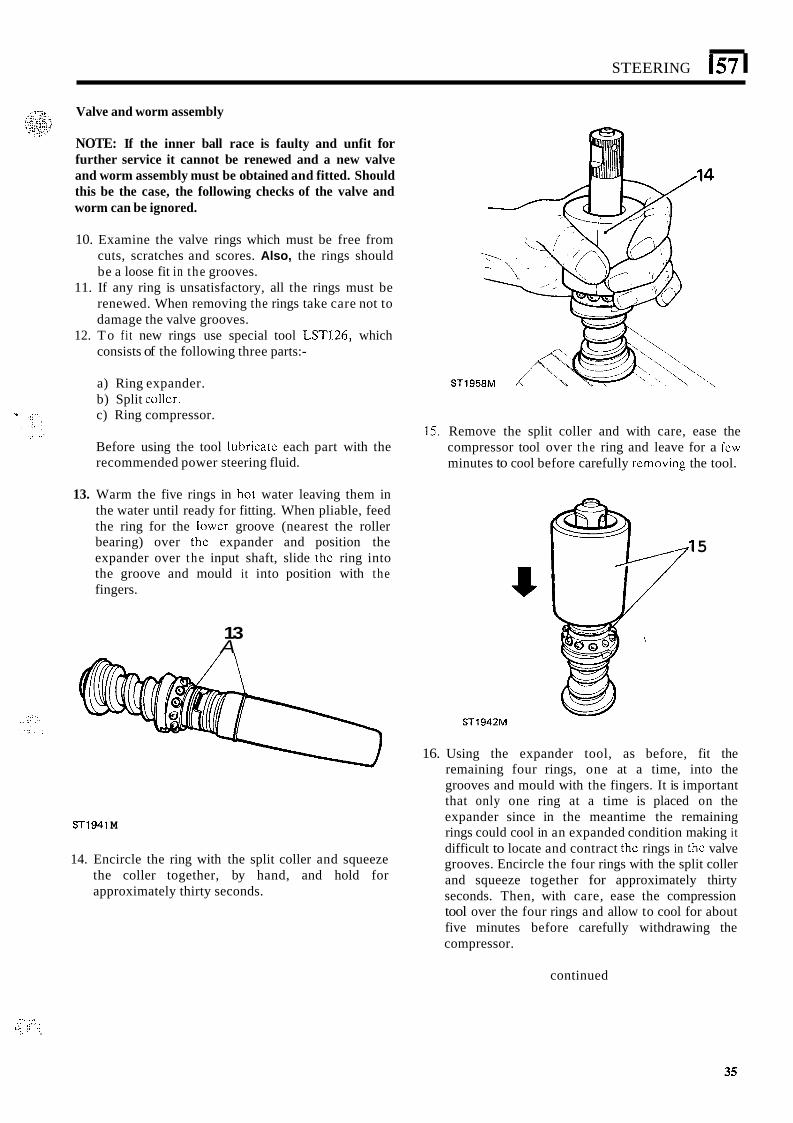
13. Warm the five rings in hol water leaving them in the water until ready for fitting. When pliable, feed the ring for the Iowcr groove (nearest the roller bearing) over thc expander and position the expander over the input shaft, slide thc ring into the groove and mould it into position with the fingers.
13 A
ST1941 M
14. Encircle the ring with the split coller and squeeze the coller together, by hand, and hold for approximately thirty seconds.
15. Remove the split coller and with care, ease the compressor tool over t he ring and leave for a fcw minutes to cool before carefully rcmoving the tool.
ST1942M
5
16. Using the expander tool, as before, fit the remaining four rings, one at a time, into the grooves and mould with the fingers. It is important that only one ring at a time is placed on the expander since in the meantime the remaining rings could cool in an expanded condition making it difficult to locate and contract thc rings in thc valve grooves. Encircle the four rings with the split coller and squeeze together for approximately thirty seconds. Then, with care, ease the compression tool over the four rings and allow to cool for about five minutes before carefully withdrawing the compressor.
continued
. - ._ .. .. _..‘ . .. 6.; .; .. .
35
1571 STEERING
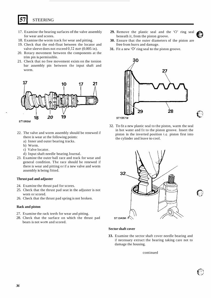
17. Examine the bearing surfaces of the valve assembly for wear and scores.
18. Examine the worm track for wear and pitting. 19. Check that the end-float between the locator and
valve sleeve does not exceed 0,12 mm (0.005 in). 20. Rotary movement between the components at the
trim pin is permissible. 21. Check that no free movement exists on the torsion
bar assembly pin between the input shaft and worm.
29. Remove the plastic seal and the ‘0’ ring seal
30. Ensure that the outer diameters of the piston are
31. Fit a new ‘0’ ring seal to the piston groove.
beneath it, from the piston groove.
free from burrs and damage.
R0 17
I
ST1957M 18 20 19 ST1955M
22. The valve and worm assembly should be renewed if there is wear at the following points: a) Inner and outer bearing tracks. b) Worm. c) Valve locator. d) Input shaft needle bearing Journal.
23. Examine the outer ball race and track for wear and general condition. The race should be renewed if there is wear and pitting or if a new valve and worm assembly is being fitted.
Thrust pad and adjuster
24. Examine the thrust pad for scores. 25. Check that the thrust pad seat in the adjuster is not
26. Check that the thrust pad spring is not broken. worn or scored.
Rack and piston
27. Examine the rack teeth for wear and pitting. 28. Check that the surface on which the thrust pad
bears is not worn and scored.
32. To fit a new plastic seal to the piston, warm the seal in hot water and fit to the piston groove. Insert the piston in the inverted position i.e. piston first into the cylinder and leave to cool.
Sector shaft cover
33. Examine the sector shaft cover needle bearing and if necessary extract the bearing taking care not to damage the housing.
continued
36
STEERING
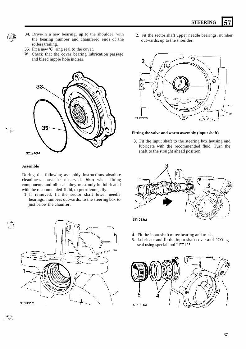
34. Drive-in a new bearing, up to the shoulder, with the bearing number and chamfered ends of the rollers trailing.
35. Fit a new ‘0’ ring seal to the cover. 36. Check that the cover bearing lubrication passage
and bleed nipple hole is clear.
57
. :.I..: .. . . . . ... .. ,
ST 1
2. Fit the sector shaft upper needle bearings, number outwards, up to the shoulder.
ST
Fitting the valve and worm assembly (input shaft)
3. Fit the input shaft to the steering box housing and lubricate with the recommended fluid. Turn the shaft to the straight ahead position.
Assemble 3 During the following assembly instructions absolute cleanliness must be observed. Also when fitting components and oil seals they must only be lubricated with the recommended fluid, or petroleum jelly. 1. If removed, fit the sector shaft lower needle
bearings, numbers outwards, to the steering box to just below the chamfer.
ST1933M
4. Fit the input shaft outer bearing and track. 5. Lubricate and fit the input shaft cover and ‘0’ ring
seal using special tool LST123.
ST1934M ST1931M
..I .. .,. ....-. . . .I.
I , .. , ..... :’
37
57
S7
STEERING
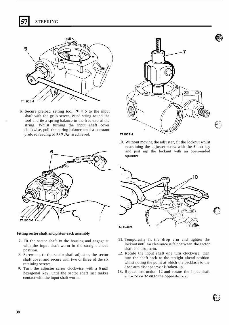
6. Secure preload setting tool R01016 to the input shaft with the grub screw. Wind string round the tool and tie a spring balance to the free end of the string. Whilst turning the input shaft cover clockwise, pull the spring balance until a constant preload reading of 0,69 Nm is achieved.
6 /
Fitting sector shaft and piston-rack assembly
7. Fit the sector shaft to the housing and engage it with the input shaft worm in the straight ahead position.
8. Screw-on, to the sector shaft adjuster, the sector shaft cover and secure with two or three of the six retaining screws.
9. Turn the adjuster screw clockwise, with a 6 mm hexagonal key, until the sector shaft just makes contact with the input shaft worm.
W ST1937M
10. Without moving the adjuster, fit the locknut whilst restraining the adjuster screw with the 6 mm key and just nip the locknut with an open-ended spanner.
'ST1938M
11.
12.
13.
Temporarily fit the drop arm and tighten the locknut until n o clearance is felt between the sector shaft and drop arm. Rotate the input shaft one turn clockwise, then turn the shaft back to the straight ahead position whilst noting the point at which the backlash to the drop arm disappears or is 'taken-up'. Repeat instruction 12 and rotate the input shaft anri-ciockwise on to the opposite iocic.
38
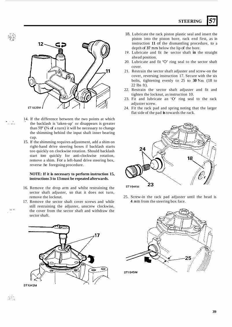
~ . .. .. . .. . . .
... .. ..,, .- / . .
STEERING 1571
14. If the difference between the two points at which the backlash is 'taken-up' or disappears is greater than 90" (9'4 of a turn) it will be necessary to change the shimming behind the input shaft inner bearing cup.
15. If the shimming requires adjustment, add a shim on right-hand drive steering boxes if backlash starts too quickly on clockwise rotation. Should backlash start too quickly for anti-clockwise rotation, remove a shim. For a left-hand drive steering box, reverse :he foregoing procedure.
*
NOTE: If it is necessary to perform instruction 15, instructions 3 to 13 must be repeated afterwards.
16. Remove the drop arm and whilst restraining the sector shaft adjuster, so that it does not turn, remove the locknut.
17. Remove the sector shaft cover screws and while still restraining the adjuster, unscrew clockwise, the cover from the sector shaft and withdraw the sector shaft.
18. Lubricate the rack piston plastic seal and insert the piston into the piston bore, rack end first, as in instruction 11 of the dismantling procedure, to a depth of 37 mm below the lip of the bore.
19. Lubricate and fit :he sector shaft in the straight ahead position.
20. Lubricate and fit '0' ring seal to the sector shaft cover.
21. Restrain the sector shaft adjuster and screw-on the cover, reversing instruction 17. Secure with the six bolts, tightening evenly to 25 to 30 Nm (18 to 22 lbs ft).
22. Restrain the sector shaft adjuster and fit and tighten the locknut, as instruction 10.
23. Fit and lubricate an '0' ring seal to the rack adjuster screw.
24. Fit the rack pad and spring noting that the larger flat side of the pad is towards the rack.
25. Screw-in the rack pad adjuster until the head is 4 mm from the steering box face.
I ST1943M
39
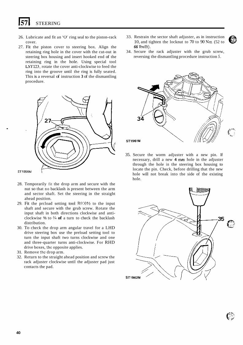
1571 STEERING
26. Lubricate and fit an ‘0’ ring seal to the piston-rack cover.
27. Fit the piston cover to steering box. Align the retaining ring hole in the cover with the cut-out in steering box housing and insert hooked end of the retaining ring in the hole. Using special tool LST123, rotate the cover anti-clockwise to feed the ring into the groove until the ring is fully seated. This is a reversal of instruction 3 of the dismantling procedure.
.
ST1956M \
28. Temporarily fi t the drop arm and secure with the nut so that n o backlash is present between the arm and sector shaft. Set the steering in the straight ahead position.
29. Fit the prcload setting tool R01016 to the input shaft and secure with the grub screw. Rotate the input shaft in both directions clockwise and anti- clockwise % to 3/4 of a turn to check the backlash distribution.
30. To check the drop arm angular travel for a LHD drive steering box use the preload setting tool to turn the input shaft two turns clockwise and one and three-quarter turns anti-clockwise. For RHD drive boxes, the opposite applies.
31. Remove the drop arm. 32. Return to the straight ahead position and screw the
rack adjuster clockwise until the adjuster pad just contacts the pad.
33. Restrain the sector shaft adjuster, as in instruction 10, and tighten the locknut to 70 to 90 Nm (52 to 66 Ibs/ft).
34. Secure the rack adjuster with the grub screw, reversing the dismantling procedure instruction 5 .
ST
35. Secure the worm adjuster with a new pin. If necessary, drill a new 4 mm hole in the adjuster through the hole in the steering box housing to locate the pin. Check, before drilling that the new hole will not break into the side of the existing hole.
40
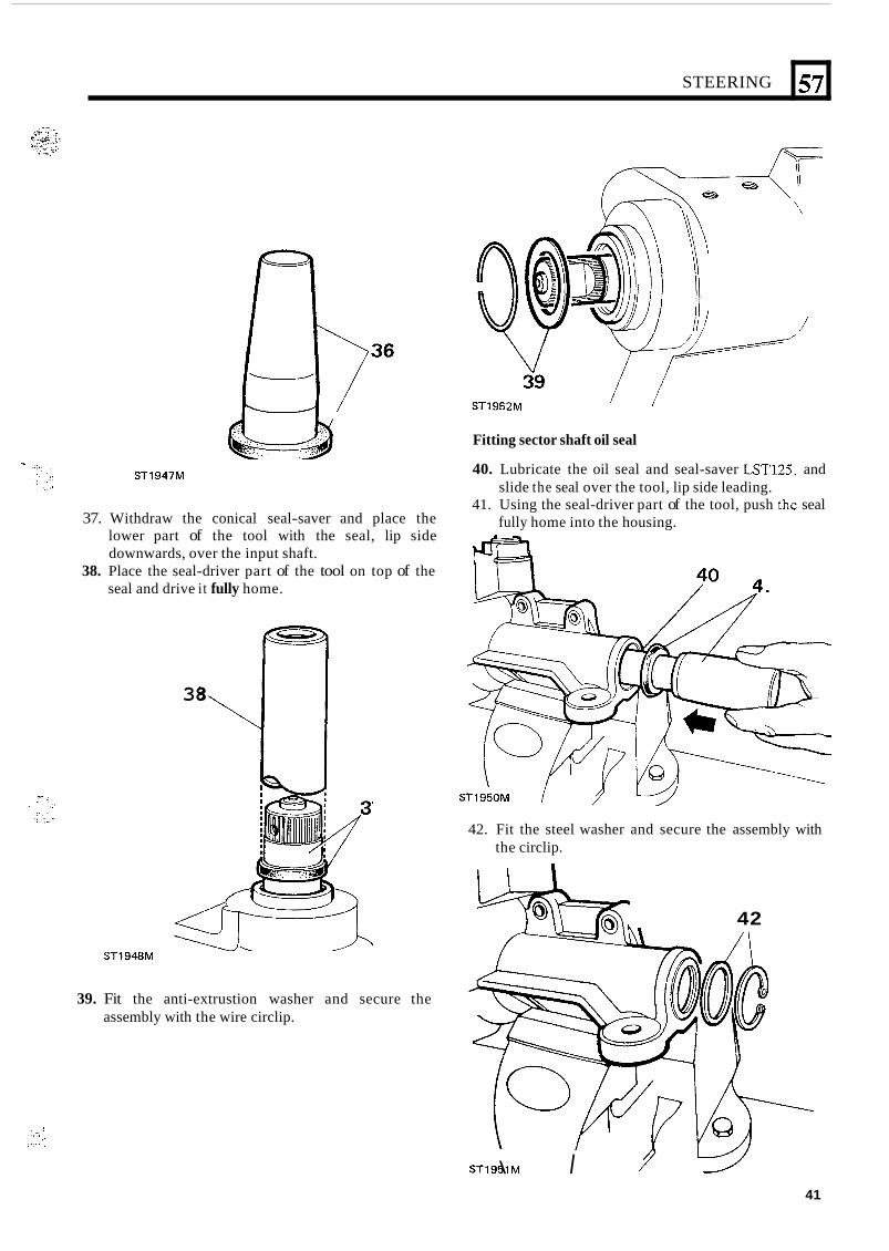
STEERING
n 57
/
ST1947M
Fitting sector shaft oil seal
40. Lubricate the oil seal and seal-saver LST12.5, and slide the seal over the tool, lip side leading.
fully home into the housing. 41. Using the seal-driver part of the tool, push thc seal
37. Withdraw the conical seal-saver and place the lower part of the tool with the seal, lip side downwards, over the input shaft.
38. Place the seal-driver part of the tool on top of the seal and drive i t fully home.
ST1948M
38
ST1950M
42. Fit the steel washer and secure the assembly with the circlip.
39. Fit the anti-extrustion washer and secure the assembly with the wire circlip.
42
ST1951M \ I 41
STEERING
43. Fit the drop arm, tab washer and nut. Tighten the nut to 170 to 180 Nm (125 to 132 Ibs/ft). Fold one side of the tab washer over the drop arm and the other over a flat against the nut.
44. Refit the steering box to the vehicle and bleed the hydraulic system.
NOTE: Bleeding and test of the power steering box is the same as that for the Adwest Lightweight box.
42
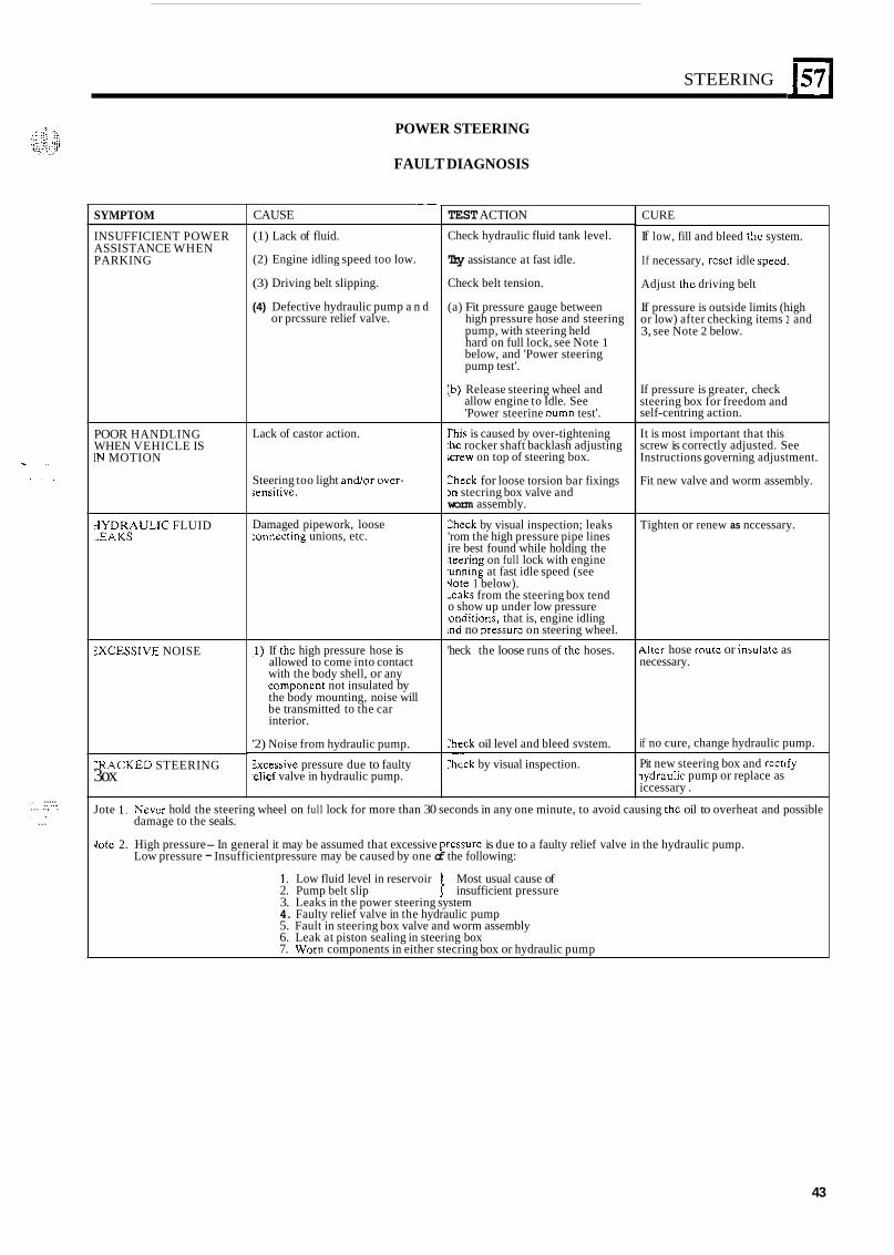
w ,. , . ,
, ..... .. .,. . , ... .,, . . . ...
STEERING 157
SYMPTOM
INSUFFICIENT POWER ASSISTANCE WHEN PARKING
POOR HANDLING WHEN VEHICLE IS [N MOTION
3YDRAULlC FLUID ,EAKS
3XCESSIVE NOISE
:RACKED STEERING 3ox
POWER STEERING
FAULT DIAGNOSIS
P
CAUSE
(1) Lack of fluid.
(2) Engine idling speed too low.
(3) Driving belt slipping.
(4) Defective hydraulic pump a n d or prcssure relief valve.
Lack of castor action.
Steering too light and/or over- jensitive.
Damaged pipework, loose :onnecting unions, etc.
:I) If thc high pressure hose is allowed to come into contact with the body shell, or any component not insulated by the body mounting, noise will be transmitted to the car interior.
'2) Noise from hydraulic pump.
Zxcessive pressure due to faulty ,elief valve in hydraulic pump.
~~ ~ ~ ~~
TEST ACTION
Check hydraulic fluid tank level.
Try assistance at fast idle.
Check belt tension.
(a) Fit pressure gauge between high pressure hose and steering pump, with steering held hard on full lock, see Note 1 below, and 'Power steering pump test'.
[b) Release steering wheel and allow engine to Idle. See 'Power steerine Dumu test'.
~ ~ ~~ ~~~ ~~ ~ ~~
l l is is caused by over-tightening :he rocker shaft backlash adjusting mew on top of steering box.
:heck for loose torsion bar fixings In stecring box valve and worm assembly.
:heck by visual inspection; leaks 'rom the high pressure pipe lines ire best found while holding the ;teering on full lock with engine wnning at fast idle speed (see 'Jote 1 below). x a k s from the steering box tend o show up under low pressure :onditions, that is, engine idling md no uressurc on steering wheel.
'heck the loose runs of the hoses.
:heck oil level and bleed svstem. ~~
Zhcck by visual inspection.
CURE
If low, fill and bleed thc system.
If necessary, reset idle specd.
Adjust thc driving belt
If pressure is outside limits (high or low) after checking items 1 and 3, see Note 2 below.
If pressure is greater, check steering box for freedom and self-centring action.
It is most important that this screw is correctly adjusted. See Instructions governing adjustment.
Fit new valve and worm assembly.
Tighten or renew as nccessary.
4lter hose routc or insulatc as necessary.
if no cure, change hydraulic pump.
Pit new steering box and rcctify iydraulic pump or replace as iccessary .
Jote 1. Never hold the steering wheel on full lock for more than 30 seconds in any one minute, to avoid causing the oil to overheat and possible damage to the seals.
riotc 2. High pressure- In general it may be assumed that excessive pressurc is due to a faulty relief valve in the hydraulic pump. Low pressure - Insufficient pressure may be caused by one of the following:
1 . Low fluid level in reservoir Most usual cause of 2. Pump belt slip } insufficient pressure 3. Leaks in the power steering system 4. Faulty relief valve in the hydraulic pump 5. Fault in steering box valve and worm assembly 6. Leak at piston sealing in steering box 7. Worn components in either stecring box or hydraulic pump
43
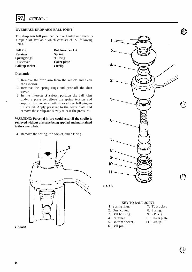
OVERHAUL DROP ARM BALL JOINT
.
The drop arm ball joint can be overhauled and there is a repair kit available which consists of the following items.
Ball Pin Ball lower socket Retainer Spring Spring rings ‘0’ ring Dust cover Cover plate Ball top socket Circlip
Dismantle
1. Remove the drop arm from the vehicle and clean the exterior.
2. Remove the spring rings and prise-off the dust cover.
3. In the interests of safety, position the ball joint under a press to relieve the spring tension and support the housing both sides of the ball pin, as illustrated. Apply pressure to the cover plate and remove the circlip and slowly release the pressure.
WARNING: Personal injury could result if the circlip is removed without pressure being applied and maintained to the cover plate.
4. Remove the spring, top socket, and ‘0’ ring.
ST1382M
ST138lM
KEY TO BALL JOINT 1. Spring rings. 7. Topsocket 2. Dust cover. 8. Spring. 3. Ball housing. 9. ‘O’ring. 4. Retainer. 10. Cover plate 5 . Bottom socket. 11. Circlip. 6. Ball pin.
44
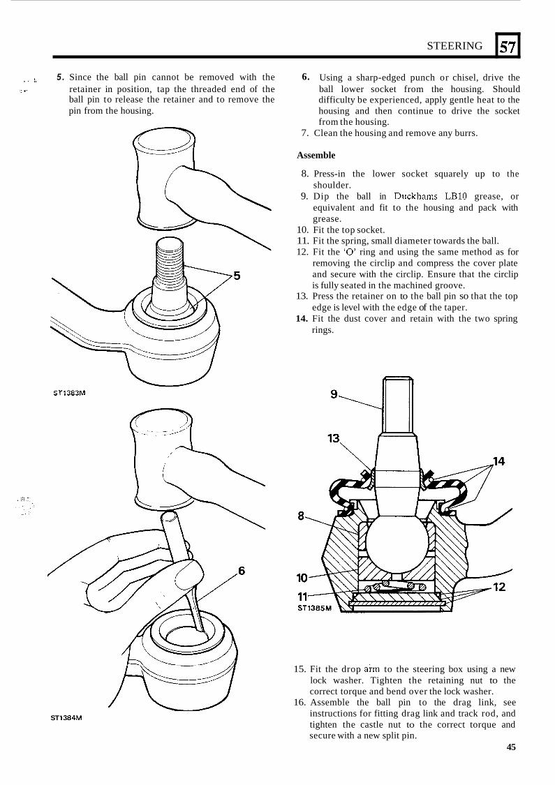
STEERING
. I !. 5 . Since the ball pin cannot be removed with the
ball pin to release the retainer and to remove the pin from the housing.
6. Using a sharp-edged punch or chisel, drive the i: 4- retainer in position, tap the threaded end of the ball lower socket from the housing. Should
difficulty be experienced, apply gentle heat to the housing and then continue to drive the socket from the housing.
7. Clean the housing and remove any burrs.
Assemble
8. Press-in the lower socket squarely up to the shoulder.
9. Dip the ball in Duckhams LBlO grease, or equivalent and fit to the housing and pack with grease.
10. Fit the top socket. 11. Fit the spring, small diameter towards the ball. 12. Fit the ‘0’ ring and using the same method as for
removing the circlip and compress the cover plate and secure with the circlip. Ensure that the circlip is fully seated in the machined groove.
13. Press the retainer on to the ball pin so that the top edge is level with the edge of the taper.
14. Fit the dust cover and retain with the two spring rings.
ST1383M
57
ST 1384M
15. Fit the drop akrn to the steering box using a new lock washer. Tighten the retaining nut to the correct torque and bend over the lock washer.
16. Assemble the ball pin to the drag link, see instructions for fitting drag link and track rod, and tighten the castle nut to the correct torque and secure with a new split pin.
45
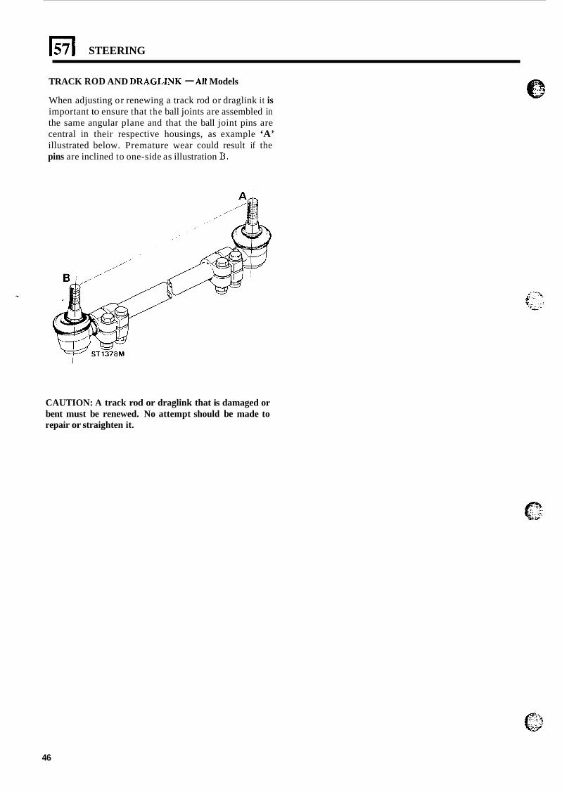
El STEERING
TRACK ROD AND DRAGLINK - All Models
When adjusting or renewing a track rod or draglink it is important to ensure that the ball joints are assembled in the same angular plane and that the ball joint pins are central in their respective housings, as example ‘A’ illustrated below. Premature wear could result if the pins are inclined to one-side as illustration B.
CAUTION: A track rod or draglink that is damaged or bent must be renewed. No attempt should be made to repair or straighten it.
46
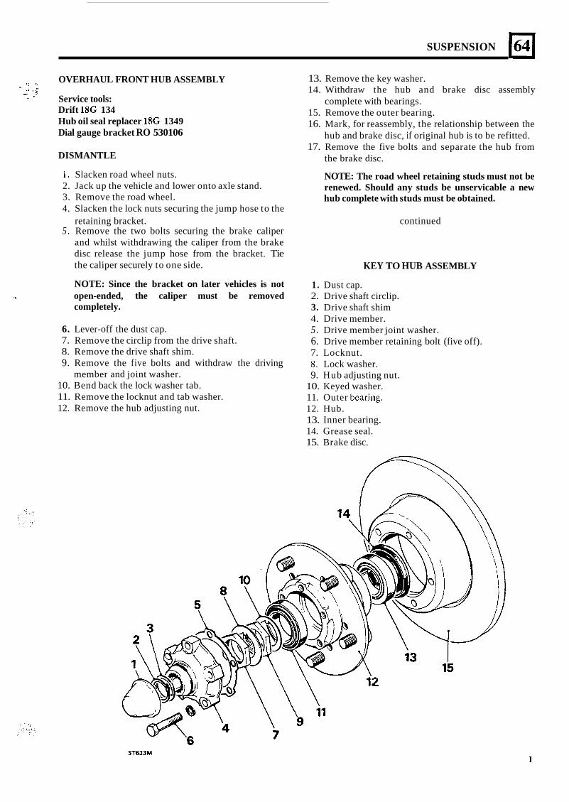
SUSPENSION
OVERHAUL FRONT HUB ASSEMBLY ., i I. .. . i
x- - * Service tools: Drift 18G 134 Hub oil seal replacer 1SG 1349 Dial gauge bracket RO 530106
DISMANTLE
13. Remove the key washer. 14. Withdraw the hub and brake disc assembly
complete with bearings. 15. Remove the outer bearing. 16. Mark, for reassembly, the relationship between the
17. Remove the five bolts and separate the hub from hub and brake disc, if original hub is to be refitted.
the brake disc.
1. Slacken road wheel nuts. 2. Jack up the vehicle and lower onto axle stand. 3. Remove the road wheel. 4. Slacken the lock nuts securing the jump hose to the
retaining bracket. continued 5 . Remove the two bolts securing the brake caliper
and whilst withdrawing the caliper from the brake disc release the jump hose from the bracket. Tie the caliper securely to one side.
NOTE: The road wheel retaining studs must not be renewed. Should any studs be unservicable a new hub complete with studs must be obtained.
KEY TO HUB ASSEMBLY
NOTE: Since the bracket on later vehicles is not
completely. 1 open-ended, the caliper must be removed
6. Lever-off the dust cap. 7. Remove the circlip from the drive shaft. 8. Remove the drive shaft shim. 9. Remove the five bolts and withdraw the driving
member and joint washer. 10. Bend back the lock washer tab. 11. Remove the locknut and tab washer. 12. Remove the hub adjusting nut.
1. Dust cap. 2. Drive shaft circlip. 3. Drive shaft shim 4. Drive member. 5. Drive member joint washer. 6. Drive member retaining bolt (five off). 7. Locknut. 8. Lock washer. 9. Hub adjusting nut.
10. Keyed washer. 11. Outer bcaring. 12. Hub. 13. Inner bearing. 14. Grease seal. 15. Brake disc.
ST633M
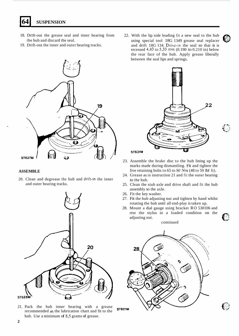
SUSPENSION
18. Drift-out the grease seal and inner bearing from
19. Drift-out the inner and outer bearing tracks.
22. With the lip side leading fit a new seal to the hub using special tool 18G 1349 grease seal replacer and drift 18G 134. Drive-In the seal so that it is recessed 4,83 to 5,33 mm (0.190 to 0.210 in) below the rear face of the hub. Apply grease liberally between the seal lips and springs.
the hub and discard the seal.
pJ
2
ST631M
23. Assemble the brake disc to the hub lining up the marks made during dismantling. Fit and tighten the five retaining bolts to 65 to 80 Nm (48 to 59 Ibf ft).
24. Grease as in instruction 21 and fit the outer bearing to the hub.
25. Clean the stub axle and drive shaft and fit the hub assembly to the axle.
26. Fit the key washer. 27. Fit the hub adjusting nut and tighten by hand whilst
rotating the hub until all end-play is taken up. 28. Mount a dial gauge using bracket RO 530106 and
rest the stylus in a loaded condition on the adjusting nut.
ASSEMBLE
20. Clean and degrease the hub and drift-in the inner and outer bearing tracks.
continued
ST6
21. Pack the hub inner bearing with a grease recommended In the lubrication chart and fit to the ST6*lM
hub. Use a minimum of 8,5 grams of grease. 2
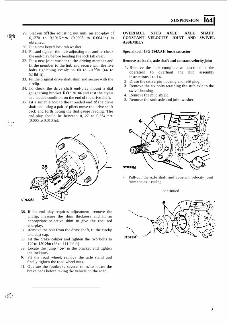
SUSPENSION 164 I
. ; I - .~~ t - . y .' 29. Slacken off the adjusting nut until an end-play of
0,1270 to 0,1016 mm (0.0005 to 0.004 in) is obtained.
* - -%E,-
30. Fit a new keyed lock tab washer. 31. Fit and tighten the hub adjusting nut and re-check
the end-play before bending the lock tab over. 32. Fit a new joint washer to the driving member and
fit the member to the hub and secure with the five bolts tightening evcnly to 60 to 70 Nm (44 to 52 Ibf ft).
33. Fit the original drive shaft shim and secure with the circlip.
34. To check the drive shaft end-play mount a dial gauge using bracket RO 530106 and rest the stylus in a loaded condition on the end of the drive shaft.
35. Fit a suitable bolt to the threaded end of the drive
OVERHAUL STUB AXLE, AXLE SHAFT, CONSTANT VELOCITY JOINT AND SWIVEL ASSEMBLY
Special tool: 18G 284AAH bush extractor
Remove stub axle, axle shaft and constant velocity joint
1. Remove the hub complete as described in the operation to overhaul the hub assembly instructions 1 to 14.
2. Drain the swivel pin housing and refit plug. 3. Remove the six bolts retaining the stub axle to the
4. Remove the mud shield. 5. Remove the stub axle and joint washer.
swivel housing.
. ,.. /.
... i:.
. . .. . . . ,.
.. .
shaft and using a pair of pliers move the drive shaft back and forth noting the dial gauge reading. The end-play should be between 0,127 to 0,254 mm (0.005 to 0.010 in).
6. Pull-out the axle shaft and constant velocity joint from the axle casing.
continued
*. . . 36. If the end-play requires adjustment, remove the
circlip, measure the shim thickness and fit an appropriate selective shim to give the required end-play.
37. Remove the bolt from the drive shaft, fit the circlip and dust cap.
38. Fit the brake caliper and tighten the two bolts to 120 to 150 Nm (88 to 111 Ibf ft).
39. Locate the jump hosc in the bracket and tighten the locknuts.
40. Fit the road wheel, remove the axle stand and finally tighten the road wheel nuts.
41. Operate the footbrakc several times to locate the brake pads before taking the vehicle on the road.
3
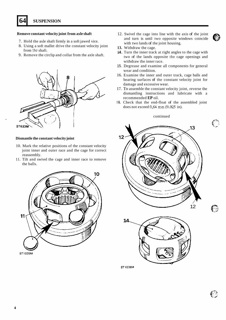
64
Remove constant velocity joint from axle shaft
7. Hold the axle shaft firmly in a soft jawed vice. 8. Using a soft mallet drive the constant velocity joint
9. Remove the circlip and collar from the axle shaft. from thc shaft.
SUSPENSION
.e I
12.
13. i4.
15.
16.
17.
18.
Swivel the cage into line with the axis of the joint and turn is until two opposite windows coincide with two lands of the joint housing. Withdraw the cage. Turn the inner track at right angles to the cage with two of the lands opposite the cage openings and withdraw the inner race. Degrease and examine all components for general wear and condition. Examine the inner and outer track, cage balls and bearing surfaces of the constant velocity joint for damage and excessive wear. To assemble the constant velocity joint, reverse the dismantling instructions and lubricate with a recommended EP oil. Check that the end-float of the assembled joint does not exceed 0,64 mm (0.025 in).
continued
Dismantle the constant velocity joint
10. Mark the relative positions of the constant velocity joint inner and outer race and the cage for correct reassembly.
11. Tilt and swivel the cage and inner race to remove the balls.
- 12
ST1025M
14
ST1026M
4
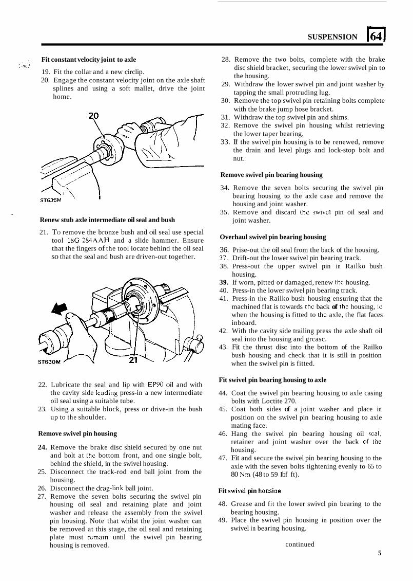
SUSPENSION El .
, " 9 ,
Fit constant velocity joint to axle
19. Fit the collar and a new circlip. 20. Engage the constant velocity joint on the axle shaft
splines and using a soft mallet, drive the joint home.
I ST636M
1(
Renew stub axle intermediate oil seal and bush
21. TO remove the bronze bush and oil seal use special tool 18G 284AAH and a slide hammer. Ensure that the fingers of the tool locate behind the oil seal so that the seal and bush are driven-out together.
22. Lubricate the seal and lip with EP90 oil and with the cavity side lcading press-in a new intermediate oil seal using a suitable tube.
23. Using a suitable block, press or drive-in the bush up to the shoulder.
Remove swivel pin housing
24. Remove the brake disc shield secured by one nut and bolt at the bottom front, and one single bolt, behind the shield, in the swivel housing.
25. Disconnect the track-rod end ball joint from the housing.
26. Disconnect the drag-link ball joint. 27. Remove the seven bolts securing the swivel pin
housing oil seal and retaining plate and joint washer and release the assembly from the swivel pin housing. Note that whilst the joint washer can be removed at this stage, the oil seal and retaining plate must remain until the swivel pin bearing housing is removed.
28. Remove the two bolts, complete with the brake disc shield bracket, securing the lower swivel pin to the housing.
29. Withdraw the lower swivel pin and joint washer by tapping the small protruding lug.
30. Remove the top swivel pin retaining bolts complete with the brake jump hose bracket.
31. Withdraw the top swivel pin and shims. 32. Remove the swivel pin housing whilst retrieving
the lower taper bearing. 33. If the swivel pin housing is to be renewed, remove
the drain and level plugs and lock-stop bolt and nut.
Remove swivel pin bearing housing
34. Remove the seven bolts securing the swivel pin bearing housing to the axle case and remove the housing and joint washer.
35. Remove and discard the swivcl pin oil seal and joint washer.
Overhaul swivel pin bearing housing
36. Prise-out the oil seal from the back of the housing. 37. Drift-out the lower swivel pin bearing track. 38. Press-out the upper swivel pin in Railko bush
39. If worn, pitted or damaged, renew thc housing. 40. Press-in the lower swivel pin bearing track. 41. Press-in the Railko bush housing ensuring that the
machined flat is towards thc back of thc housing, ic when the housing is fitted to thc axle, the flat faces inboard.
42. With the cavity side trailing press the axle shaft oil seal into the housing and grcasc.
43. Fit the thrust disc into the bottom of the Railko bush housing and check that it is still in position when the swivel pin is fitted.
housing.
Fit swivel pin bearing housing to axle
44. Coat the swivel pin bearing housing to axle casing bolts with Loctite 270.
45. Coat both sides of a joint washer and place in position on the swivel pin bearing housing to axle mating face.
46. Hang the swivel pin bearing housing oil seal, retainer and joint washer over the back of thc housing.
47. Fit and secure the swivel pin bearing housing to the axle with the seven bolts tightening evenly to 65 to 80 Nm (48 to 59 Ibf ft).
Fit swive! pi,n, hcusinn 6
48. Grease and f i t the lower swivcl pin bearing to the
49. Place the swivel pin housing in position over the bearing housing.
swivel in bearing housing.
continued 5
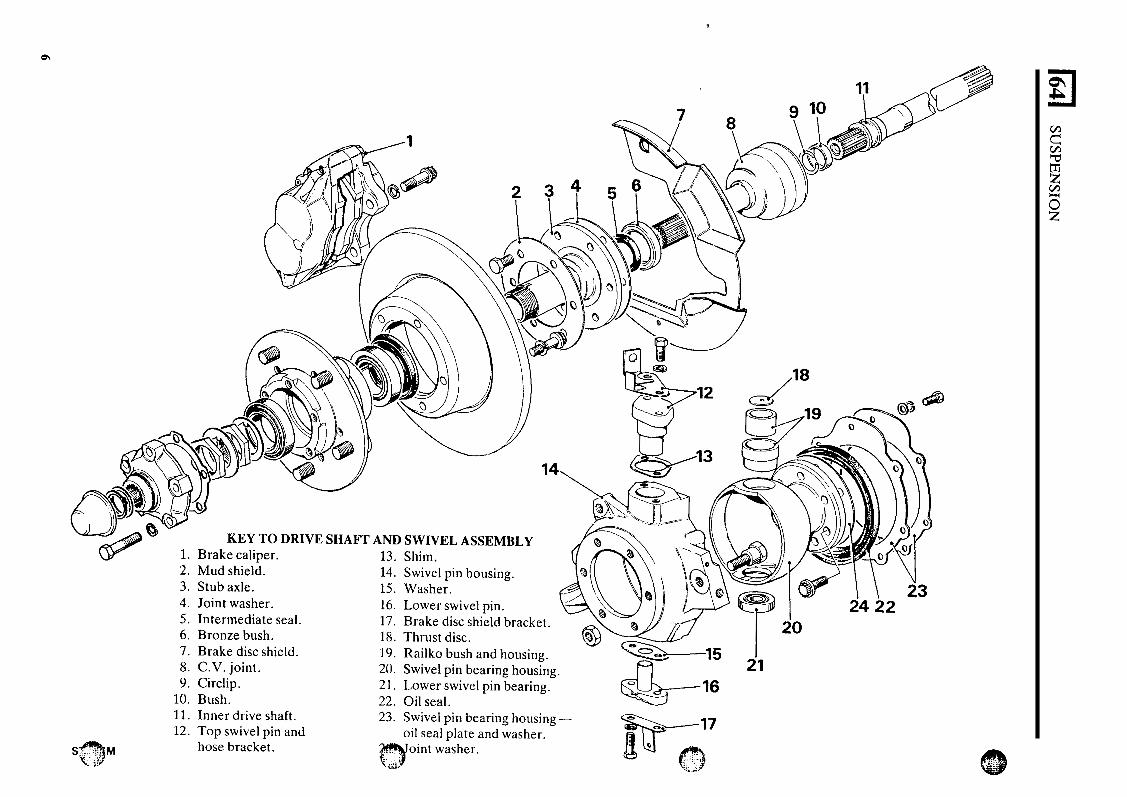
,
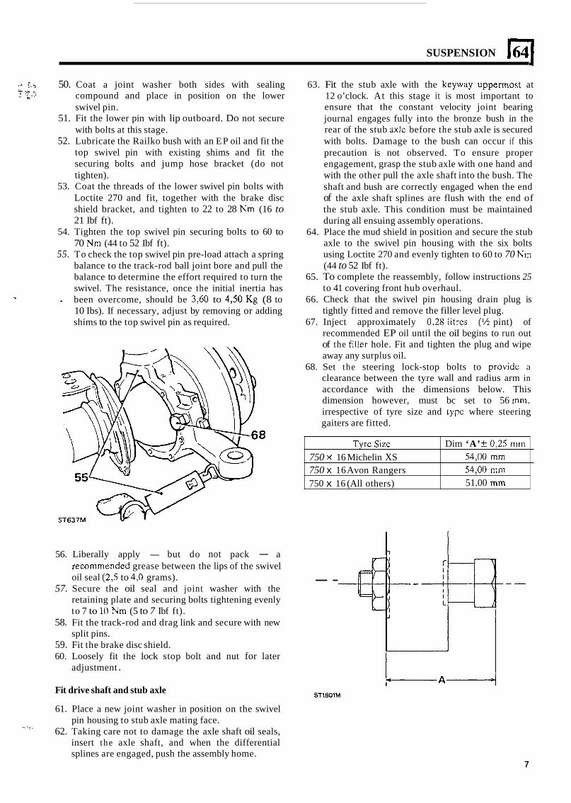
SUSPENSION E(
Tyrc Size 750 x 16 Michelin XS 750 x 16 Avon Rangers 750 x 16 (All others)
c J I. . ; 50. Coat a joint washer both sides with sealing compound and place in position on the lower swivel pin.
51. Fit the lower pin with lip outboard. Do not secure with bolts at this stage.
52. Lubricate the Railko bush with an EP oil and fit the top swivel pin with existing shims and fit the securing bolts and jump hose bracket (do not tighten).
53. Coat the threads of the lower swivel pin bolts with Loctite 270 and fit, together with the brake disc shield bracket, and tighten to 22 to 28 Nm (16 to 21 Ibf ft).
54. Tighten the top swivel pin securing bolts to 60 to 70 Nm (44 to 52 Ibf ft).
55. To check the top swivel pin pre-load attach a spring balance to the track-rod ball joint bore and pull the balance to determine the effort required to turn the swivel. The resistance, once the initial inertia has been overcome, should be 3,60 to 4 3 0 Kg (8 to 10 Ibs). If necessary, adjust by removing or adding shims to the top swivel pin as required.
i r .R ., ” * ’ . ,..
% -
Dim ‘A’ & 0,25 mm 54,OO mm 54,OO mm 51.00 mm
63. Fit the stub axle with the keyway uppermost at 12 o’clock. At this stage it is most important to ensure that the constant velocity joint bearing journal engages fully into the bronze bush in the rear of the stub axlc before the stub axle is secured with bolts. Damage to the bush can occur if this precaution is not observed. To ensure proper engagement, grasp the stub axle with one hand and with the other pull the axle shaft into the bush. The shaft and bush are correctly engaged when the end of the axle shaft splines are flush with the end of the stub axle. This condition must be maintained during all ensuing assembly operations.
64. Place the mud shield in position and secure the stub axle to the swivel pin housing with the six bolts using Loctite 270 and evenly tighten to 60 to 70 Nm (44 to 52 Ibf ft).
65. To complete the reassembly, follow instructions 25 to 41 covering front hub overhaul.
66. Check that the swivel pin housing drain plug is tightly fitted and remove the filler level plug.
67. Inject approximately 0,28 litres (% pint) of recommended EP oil until the oil begins to run out of the filler hole. Fit and tighten the plug and wipe away any surplus oil.
68. Set the steering lock-stop bolts to providc a clearance between the tyre wall and radius arm in accordance with the dimensions below. This dimension however, must bc set to 56 mm, irrespective of tyre size and type where steering gaiters are fitted.
56. Liberally apply - but do not pack - a recommendcd grease between the lips of the swivel oil seal (2,5 to 4,O grams).
57. Secure the oil seal and joint washer with the retaining plate and securing bolts tightening evenly to 7 to 10 Nm (5 to 7 Ibf ft).
58. Fit the track-rod and drag link and secure with new split pins.
59. Fit the brake disc shield. 60. Loosely fit the lock stop bolt and nut for later
adjustment .
- -
ST18OlM Fit drive shaft and stub axle
61. Place a new joint washer in position on the swivel pin housing to stub axle mating face.
62. Taking care not to damage the axle shaft oil seals, insert the axle shaft, and when the differential splines are engaged, push the assembly home.
, .
7
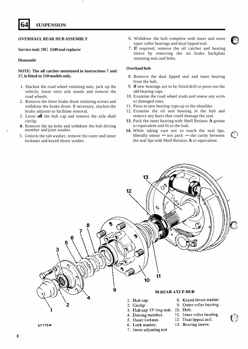
64
OVERHAUL REAR HUB ASSEMBLY
Service tool: 18G 1349 seal replacer
Dismantle
NOTE: The oil catcher mentioned in instructions 7 and 17, is fitted to 110 models only.
SUSPENSION
1. Slacken the road wheel retaining nuts, jack up the vehicle, lower onto axle stands and remove the road wheels.
2. Remove the three brake drum retaining screws and withdraw the brake drum. If necessary, slacken the brake adjuster to facilitate removal.
3. Lever off the hub cap and remove the axle shaft circlip.
4. Remove the six bolts and withdraw the hub driving
5. Unlock the tab washer, remove the outer and inner 1 member and joint washer.
locknuts and keyed thrust washer.
6. Withdraw the hub complete with inner and outer taper roller bearings and dual lipped seal.
7. If required, remove the oil catcher and bearing sleeve by removing the six brake backplate retaining nuts and bolts.
Overhaul hub
8. Remove the dual lipped seal and inner bearing
9. If new bearings are to be fitted drift or press out the
10. Examine the road wheel studs and renew any worn
11. Press in new bearing cups up to the shoulder. 12. Examine the oil seal housing in the hub and
remove any burrs that could damage the seal. 13. Pack the inner bearing with Shell Retinax A grease
or equivalent and fit to the hub. 14. While taking care not to touch the seal lips,
liberally smear - not pack - the cavity between the seal lips with Shell Retinax A or equivalent.
from the hub.
old bearing cups.
o r damaged ones.
$3 %*’
8
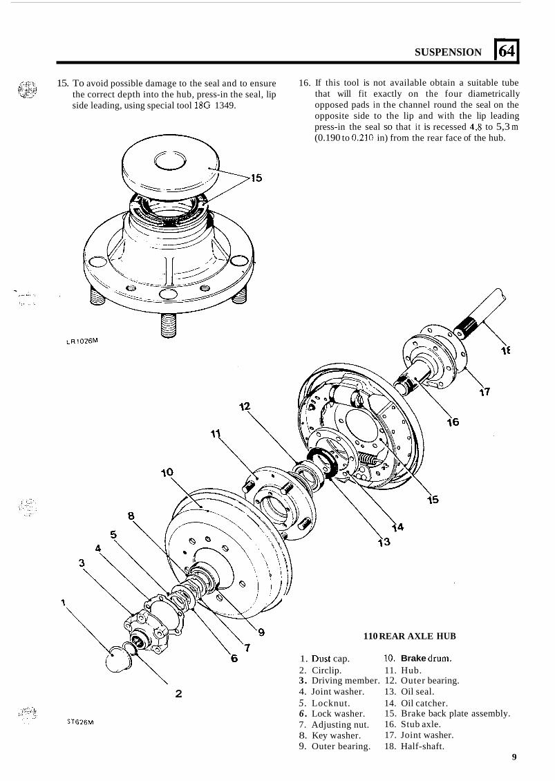
SUSPENSION 164
15. To avoid possible damage to the seal and to ensure the correct depth into the hub, press-in the seal, lip side leading, using special tool 18G 1349.
16. If this tool is not available obtain a suitable tube that will fit exactly on the four diametrically opposed pads in the channel round the seal on the opposite side to the lip and with the lip leading press-in the seal so that it is recessed 4,s to 5,3 m (0.190 to 0.210 in) from the rear face of the hub.
. . . . . .. ... ,..,. ,
i ., . , , ..
110 REAR AXLE HUB
2
1. Dust cap. 10. Brake dru!??. 2. Circlip. 11. Hub. 3. Driving member. 12. Outer bearing. 4. Joint washer. 13. Oil seal. 5. Locknut. 14. Oil catcher. 6 . Lock washer. 7. Adjusting nut. 8. Key washer. 9. Outer bearing. 18. Half-shaft.
15. Brake back plate assembly. 16. Stub axle. 17. Joint washer.
9
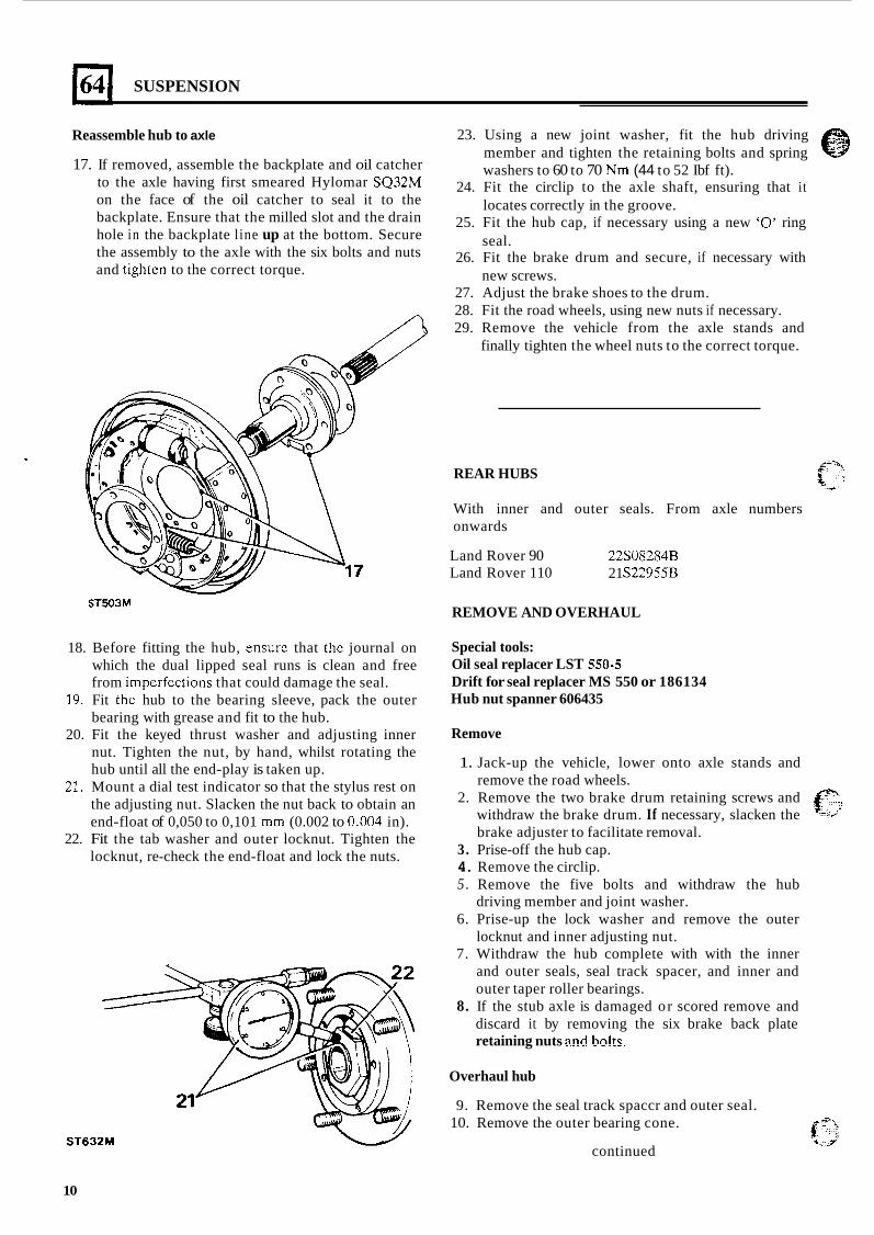
SUSPENSION
Reassemble hub to axle
17. If removed, assemble the backplate and oil catcher to the axle having first smeared Hylomar SQ32M on the face of the oil catcher to seal it to the backplate. Ensure that the milled slot and the drain hole in the backplate line up at the bottom. Secure the assembly to the axle with the six bolts and nuts and tightcn to the correct torque.
ST503M
18. Before fitting the hub, ensurc that thc journal on which the dual lipped seal runs is clean and free from imperfcctions that could damage the seal.
19. Fit the hub to the bearing sleeve, pack the outer bearing with grease and fit to the hub.
20. Fit the keyed thrust washer and adjusting inner nut. Tighten the nut, by hand, whilst rotating the hub until all the end-play is taken up.
21. Mount a dial test indicator so that the stylus rest on the adjusting nut. Slacken the nut back to obtain an end-float of 0,050 to 0,101 mm (0.002 to 0.004 in).
22. Fit the tab washer and outer locknut. Tighten the locknut, re-check the end-float and lock the nuts.
ST632M
10
23. Using a new joint washer, fit the hub driving e member and tighten the retaining bolts and spring *‘
washers to 60 to 70 Nm (44 to 52 Ibf ft). 24. Fit the circlip to the axle shaft, ensuring that it
locates correctly in the groove. 25. Fit the hub cap, if necessary using a new ‘0’ ring
seal. 26. Fit the brake drum and secure, if necessary with
new screws. 27. Adjust the brake shoes to the drum. 28. Fit the road wheels, using new nuts if necessary. 29. Remove the vehicle from the axle stands and
finally tighten the wheel nuts to the correct torque.
REAR HUBS
With inner and outer seals. From axle numbers onwards
Land Rover 90 Land Rover 110
22308284B 21 S22955B
REMOVE AND OVERHAUL
Special tools: Oil seal replacer LST 550-5 Drift for seal replacer MS 550 or 186134 Hub nut spanner 606435
Remove
1. Jack-up the vehicle, lower onto axle stands and remove the road wheels.
2. Remove the two brake drum retaining screws and withdraw the brake drum. If necessary, slacken the brake adjuster to facilitate removal.
3. Prise-off the hub cap. 4. Remove the circlip. 5 . Remove the five bolts and withdraw the hub
driving member and joint washer. 6. Prise-up the lock washer and remove the outer
locknut and inner adjusting nut. 7. Withdraw the hub complete with with the inner
and outer seals, seal track spacer, and inner and outer taper roller bearings.
8. If the stub axle is damaged or scored remove and discard it by removing the six brake back plate retaining nuts and bo!ts.
Overhaul hub
9. Remove the seal track spaccr and outer seal. 10. Remove the outer bearing cone.
continued f ”’ ‘ I J
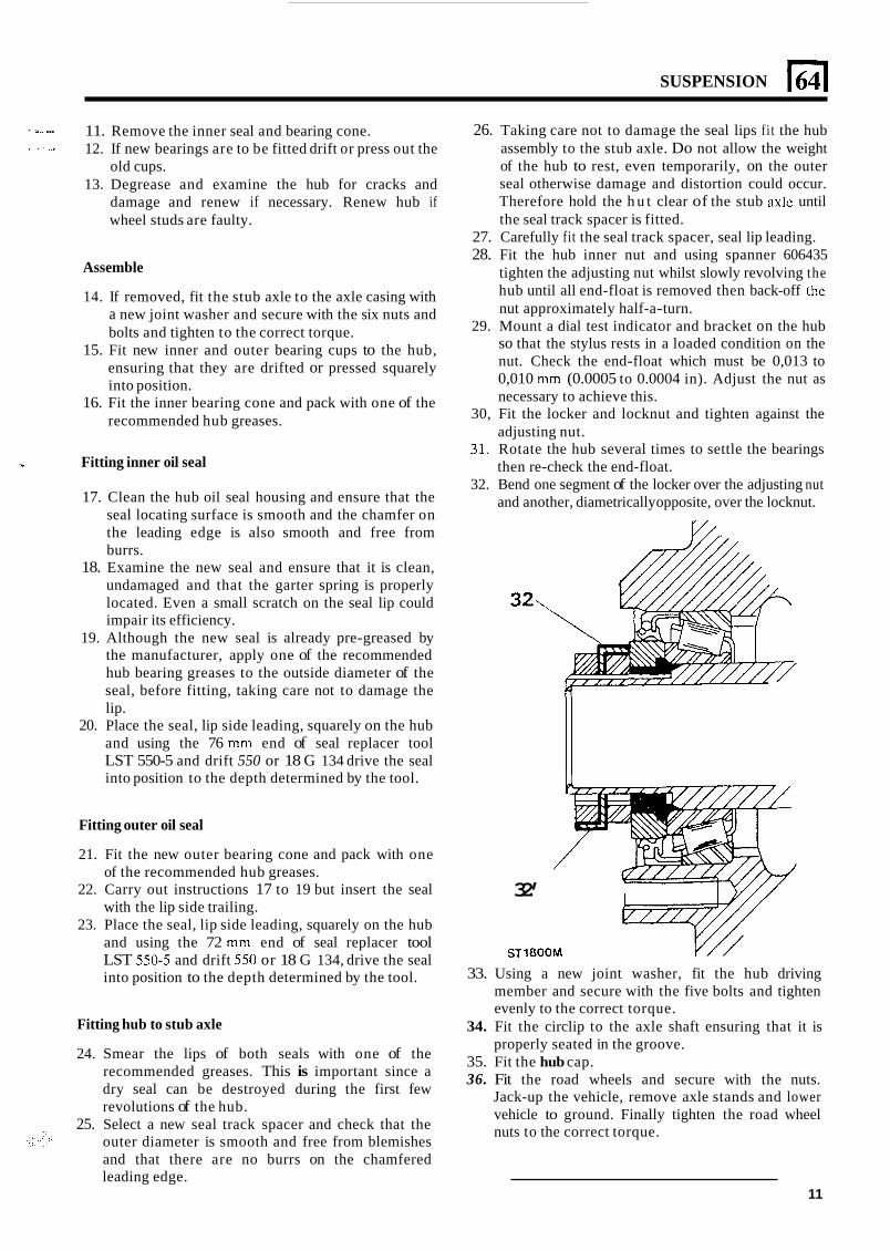
SUSPENSION
S . I ... . I
11. Remove the inner seal and bearing cone. 12. If new bearings are to be fitted drift or press out the
old cups. 13. Degrease and examine the hub for cracks and
damage and renew if necessary. Renew hub if wheel studs are faulty.
Assemble
14. If removed, fit the stub axle to the axle casing with a new joint washer and secure with the six nuts and bolts and tighten to the correct torque.
15. Fit new inner and outer bearing cups to the hub, ensuring that they are drifted or pressed squarely into position.
16. Fit the inner bearing cone and pack with one of the recommended hub greases.
- Fitting inner oil seal
17. Clean the hub oil seal housing and ensure that the seal locating surface is smooth and the chamfer on the leading edge is also smooth and free from burrs.
18. Examine the new seal and ensure that it is clean, undamaged and that the garter spring is properly located. Even a small scratch on the seal lip could impair its efficiency.
19. Although the new seal is already pre-greased by the manufacturer, apply one of the recommended hub bearing greases to the outside diameter of the seal, before fitting, taking care not to damage the lip.
20. Place the seal, lip side leading, squarely on the hub and using the 76 mm end of seal replacer tool LST 550-5 and drift 550 or 18 G 134 drive the seal into position to the depth determined by the tool.
Fitting outer oil seal
21. Fit the new outer bearing cone and pack with one of the recommended hub greases.
22. Carry out instructions 17 to 19 but insert the seal with the lip side trailing.
23. Place the seal, lip side leading, squarely on the hub and using the 72 mm end of seal replacer tool LST 550-5 and drift 550 or 18 G 134, drive the seal into position to the depth determined by the tool.
Fitting hub to stub axle
24. Smear the lips of both seals with one of the recommended greases. This is important since a dry seal can be destroyed during the first few revolutions of the hub.
25. Select a new seal track spacer and check that the outer diameter is smooth and free from blemishes
26. Taking care not to damage the seal lips f i t the hub assembly to the stub axle. Do not allow the weight of the hub to rest, even temporarily, on the outer seal otherwise damage and distortion could occur. Therefore hold the h u t clear of the stub axle until the seal track spacer is fitted.
27. Carefully fit the seal track spacer, seal lip leading. 28. Fit the hub inner nut and using spanner 606435
tighten the adjusting nut whilst slowly revolving the hub until all end-float is removed then back-off the nut approximately half-a-turn.
29. Mount a dial test indicator and bracket on the hub so that the stylus rests in a loaded condition on the nut. Check the end-float which must be 0,013 to 0,010 mm (0.0005 to 0.0004 in). Adjust the nut as necessary to achieve this.
30, Fit the locker and locknut and tighten against the adjusting nut.
31. Rotate the hub several times to settle the bearings then re-check the end-float.
32. Bend one segment of the locker over the adjusting nut and another, diametrically opposite, over the locknut.
V/ ,
32,
32’
ST1800M Y / / 33. Using a new joint washer, fit the hub driving
member and secure with the five bolts and tighten evenly to the correct torque.
34. Fit the circlip to the axle shaft ensuring that it is properly seated in the groove.
35. Fit the hub cap. 36. Fit the road wheels and secure with the nuts.
Jack-up the vehicle, remove axle stands and lower vehicle to ground. Finally tighten the road wheel nuts to the correct torque.
and that there are no burrs on the chamfered leading edge.
11
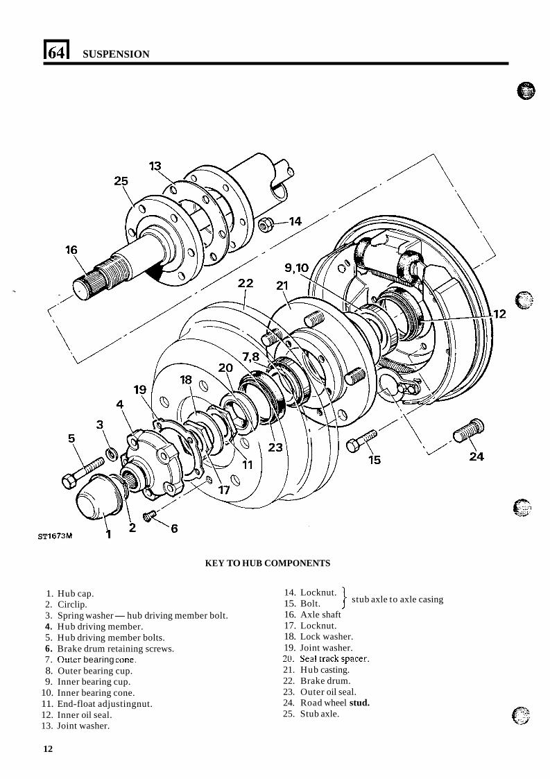
I64 1 SUSPENSION
ST
KEY TO HUB COMPONENTS
1. Hub cap. 2. Circlip. 3. Spring washer- hub driving member bolt. 4. Hub driving member. 5. Hub driving member bolts. 6. Brake drum retaining screws.
8. Outer bearing cup. 9. Inner bearing cup.
10. Inner bearing cone. 11. End-float adjustingnut. 12. Inner oil seal. 13. Joint washer.
7. Otter bearing cone.
stub axle to axle casing 14. Locknut. 15. Bolt. 16. Axle shaft 17. Locknut. 18. Lock washer. 19. Joint washer.
21. Hub casting. 22. Brake drum. 23. Outer oil seal. 24. Road wheel stud. 25. Stub axle.
20. %a! !El& SFX€!r.
12
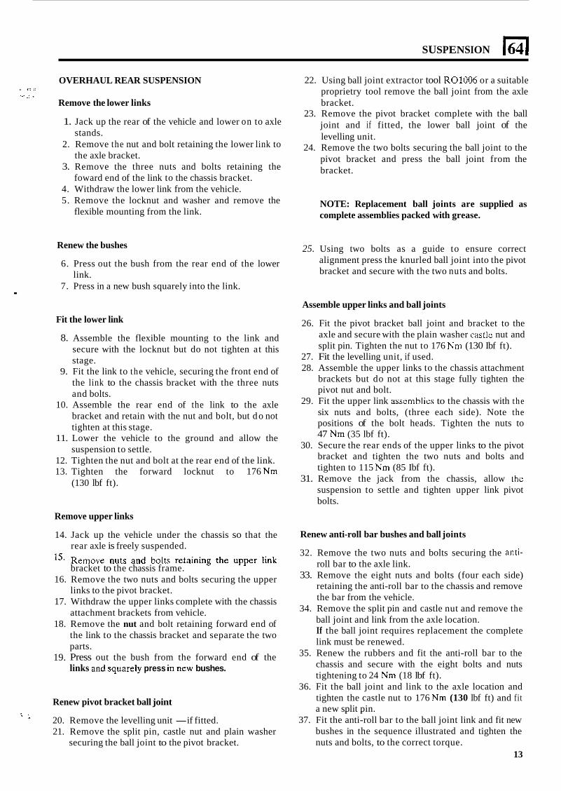
SUSPENSION 164 I
.
OVERHAUL REAR SUSPENSION
Remove the lower links
. .'. .A c. -. .
1. Jack up the rear of the vehicle and lower on to axle stands.
2. Remove the nut and bolt retaining the lower link to the axle bracket.
3. Remove the three nuts and bolts retaining the foward end of the link to the chassis bracket.
4. Withdraw the lower link from the vehicle. 5. Remove the locknut and washer and remove the
flexible mounting from the link.
Renew the bushes
6. Press out the bush from the rear end of the lower link.
7. Press in a new bush squarely into the link.
Fit the lower link
8. Assemble the flexible mounting to the link and secure with the locknut but do not tighten at this stage.
9. Fit the link to the vehicle, securing the front end of the link to the chassis bracket with the three nuts and bolts.
10. Assemble the rear end of the link to the axle bracket and retain with the nut and bolt, but do not tighten at this stage.
11. Lower the vehicle to the ground and allow the suspension to settle.
12. Tighten the nut and bolt at the rear end of the link. 13. Tighten the forward locknut to 176 Nm
(130 lbf ft).
Remove upper links
22. Using ball joint extractor tool R01006 or a suitable proprietry tool remove the ball joint from the axle bracket.
23. Remove the pivot bracket complete with the ball joint and if fitted, the lower ball joint of the levelling unit.
24. Remove the two bolts securing the ball joint to the pivot bracket and press the ball joint from the bracket.
NOTE: Replacement ball joints are supplied as complete assemblies packed with grease.
25. Using two bolts as a guide to ensure correct alignment press the knurled ball joint into the pivot bracket and secure with the two nuts and bolts.
Assemble upper links and ball joints
26. Fit the pivot bracket ball joint and bracket to the axle and secure with the plain washer castle nut and split pin. Tighten the nut to 176 Nm (130 Ibf ft).
27. Fit the levelling unit, if used. 28. Assemble the upper links to the chassis attachment
brackets but do not at this stage fully tighten the pivot nut and bolt.
29. Fit the upper link assemblics to the chassis with the six nuts and bolts, (three each side). Note the positions of the bolt heads. Tighten the nuts to 47 Nm (35 lbf ft).
30. Secure the rear ends of the upper links to the pivot bracket and tighten the two nuts and bolts and tighten to 115 Nm (85 Ibf ft).
31. Remove the jack from the chassis, allow thc suspension to settle and tighten upper link pivot bolts.
14.
15.
16.
17.
18.
19.
Jack up the vehicle under the chassis so that the rear axle is freely suspended. Remove nuts and bolts retaining the upper link bracket to the chassis frame. Remove the two nuts and bolts securing the upper links to the pivot bracket. Withdraw the upper links complete with the chassis attachment brackets from vehicle. Remove the nut and bolt retaining forward end of the link to the chassis bracket and separate the two parts. Press out the bush from the forward end of the
Renew anti-roll bar bushes and ball joints
32. Remove the two nuts and bolts securing the anti- roll bar to the axle link.
33. Remove the eight nuts and bolts (four each side) retaining the anti-roll bar to the chassis and remove the bar from the vehicle.
34. Remove the split pin and castle nut and remove the ball joint and link from the axle location. If the ball joint requires replacement the complete link must be renewed.
35. Renew the rubbers and fit the anti-roll bar to the chassis and secure with the eight bolts and nuts tightening to 24 Nm (18 lbf ft).
36. Fit the ball joint and link to the axle location and
links 2.d squ.re!y press in new bushes.
Renew pivot bracket ball joint tighten the castle nut to 176 Nm (130 lbf ft) and fit a new split pin. - - ' '- 20. Remove the levelling unit -if fitted.
21. Remove the split pin, castle nut and plain washer 37. Fit the anti-roll bar to the ball joint link and fit new
bushes in the sequence illustrated and tighten the nuts and bolts, to the correct torque.
13 securing the ball joint to the pivot bracket.
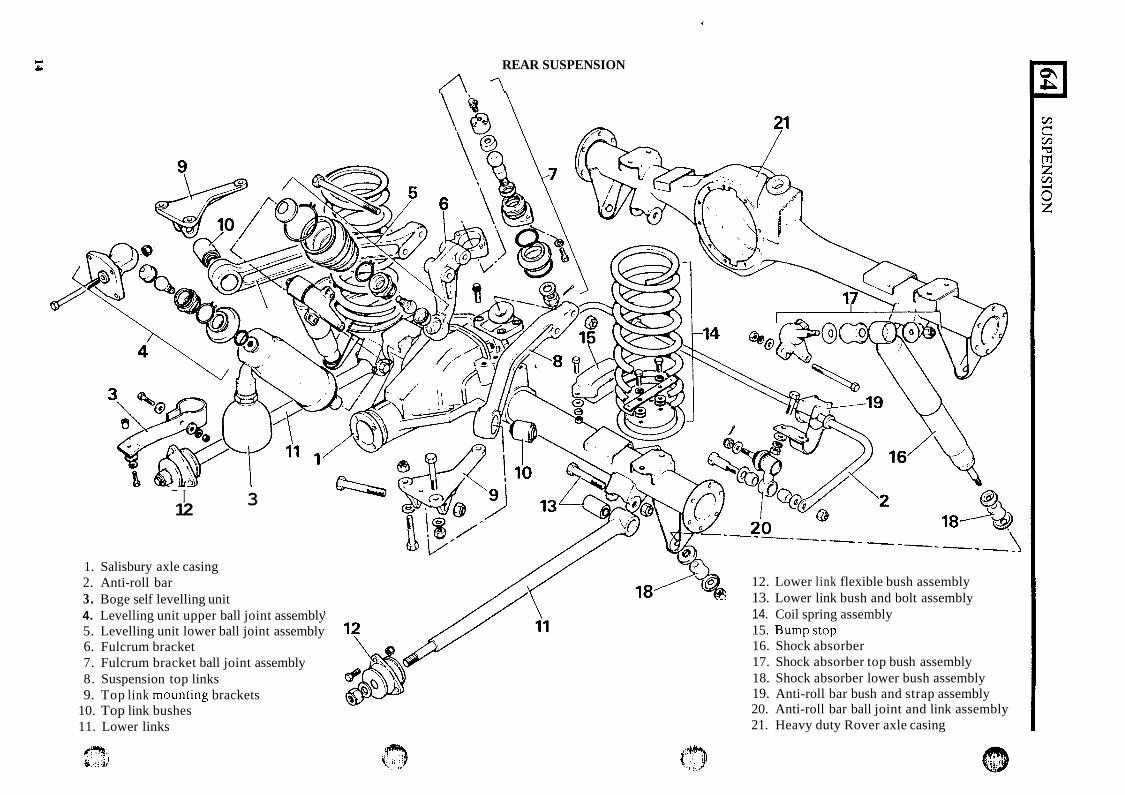
-- I 12 3
1. Salisbury axle casing 2. Anti-roll bar 3. Boge self levelling unit 4. Levelling unit upper ball joint assembly 5. Levelling unit lower ball joint assembly 6. Fulcrum bracket 7. Fulcrum bracket ball joint assembly 8. Suspension top links 9. Top link mounting brackets
10. Top link bushes 11. Lower links
f*) t i
REAR SUSPENSION
A 1
12. Lower link flexible bush assembly 13. Lower link bush and bolt assembly 14. Coil spring assembly 15. Bumpstop 16. Shock absorber 17. Shock absorber top bush assembly 18. Shock absorber lower bush assembly 19. Anti-roll bar bush and strap assembly 20. Anti-roll bar ball joint and link assembly 21. Heavy duty Rover axle casing
18
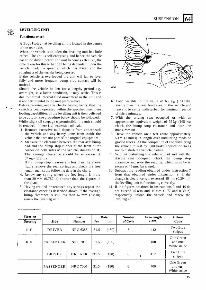
SUSPENSION
A Boge Hydromat levelling unit is located in the centre of the rear axle. When the vehicle is unladen the levelling unit has little effect. The unit is self-energising and hence the vehicle has to be driven before the unit becomes effective, the time taken for this to happen being dependant upon the vehicle load, the speed at which it is driven and the roughness of the terrain being crossed. If the vehicle is overloaded the unit will fail to level fully and more frequent bump stop contact will be noticed. Should the vehicle be left for a lengthy period e.g. overnight, in a laden condition, it may settle. This is due to normal internal fluid movement in the unit and is not detrimental to the unit performance. Before carrying out the checks below, verify that the vehicle is being operated within the specified maximum loading capabilities. If the levelling unit is then believed to be at fault, the procedure below should be followed. Whilst slight oil seepage IS permissible, the unit should be renewed if there is an excessive oil leak. 1. Remove excessive mud deposits from underneath
the vehicle and any heavy items from inside the vehicle that are not part of the original equipment.
2. Measure the clearance between the rear axle bump pad and the bump stop rubber at the front outer corner on both sides of the vehicle, dimension A. The average clearance should be in excess of 67 mm (2.8 in).
3. If thc bump stop clearance is less than the above figure remove the rear springs and check the free length against the following data in the chart.
4. Renew any spnng where the free length is more than 20 mm (0.787 in) shorter than the figures in the chart.
5. Having refitted or renewed any springs repeat the clearance check as described above. If the average bump clearance is still less than 67 mm (2.8 in) renew the levelling unit.
. ., , .
.
L
64
r-- Steering Side
1 R.H.
Part Rate Number Free length Colour Number Nm (Ibhn) ofcoils (mm) Code
t--- PASSENGER 1 R.H.
One Green and onc
White stripe ._ .-
NRC 7000 31.5 (180) 6 400
6. Load weights to the value of 650 kg (1143 Ibs) evenly over the rear load area of the vehicle and leave it to settle undisturbed for minimum period of thirty minutes.
7. With the driving seat occupied or with an approximate equivalent weight of 75 kg (165 Ibs) check the bump stop clearance and note the measurPment.
8. Drive the vehicle on a test route approximately 5 km (3 miles) in length over undulating roads or graded tracks. At the completion of the drive bring the vehicle to rest by light brake application so as not to disturb the vehicle loading.
9. Without disturbing the vehicle load and with thc driving seat occupied, check the bump stop clearance and note the reading, which must be in excess of 45 mm (average).
10. Subtract the reading obtained under Instruction 7 from that obtained under Instruction 9. If the change in clearance is in excess of 10 mm (0.394 in) the levelling unit is functioning correctly.
11. If the figures obtained in instructions 9 and 10 do not exceed 45 mm and 10 mm (1.77 and 0.39 in) respectively unload the vehicle and renew the levelling unit.
PASSENGER One Green
White stripe NRC 7000 31.5 (180) 6 400 and onc
Two Blue stripes DRIVER I NRC 6388 31.5 (180) I 6 I 412 1
Two Blue stripes DRIVER I NRC6388 131.5 (180) 1 6 1 412 1
15
1641 SUSPENSION
REMOVE LEVELLING UNIT - where fitted
WARNING: The levelling unit contains pressurised gas and must not be dismantled nor the casing screws removed. Repair is by replacement of complete unit only.
1. Raise and support the vehicle under the chassis and use a jack to support the weight of the axle.
2. Disconnect the upper links at the pivot bracket. 3. Ease up the levclling unit lower gaiter and unscrew
the lower ball joint at the push rod using thin jawed spanners.
4. Release the webbing strap from the chassis. 5 . Remove the four nuts securing the top bracket to
the chassis and withdraw the levelling unit complete with bracket.
Renew levelling unit ball joints
The-ball joints for the levelling unit may be dismantled for clcaning and cxamination. 6. Unscrew the lower ball joint from thc pivot
7. Unscrew thc ball joint from the top bracket. 8. Reassemble the ball joints, packing with
Dextagrease G.P. or equivalent or if necessary renew the joints if worn.
9. Check the condition of the gaitcrs and renew i f necessary.
1
bracket.
Fit levelling unit
10. Ensure the ball pin threads are clean and smear Loctite grade CVX on the ball pin threads.
11. Fit the upper ball joint to the levelling unit and secure the gaiter.
12. Fit the top bracket complete with levelling unit to the chassis and sccure with the four nuts and tighten to 47 Nm (35 Ibf ft).
13. Fit the levelling unit to the lower ball joint and secure the gaiter.
14. Attach the webbing strap to the chassis cross member.
15. Fit the upper links to the pivot bracket and retain with the two bolts and nuts but do not tighten at this stage.
16. Remove the jack in support of the axle and the support from under the chassis.
17. Allow the suspension to settle and then tighten the two bolts and nuts retaining the upper links to the pivot bracket to thc correct torque.
SPRINGS AND SHOCK ABSORBERS
Remove rear springs
1. Slacken the rLAr road wheel nuts and raise the rear of the vehick and lower the chassis on the axle stands or similar supports and remove the road wheels.
16
2. Support the weight of the axle with a jack. 3 . Disconnect the shock absorbers at the lower end. 4. Remove the spring retainer plate. 5. Lower the axle sufficiently to withdraw the spring,
but take care not to stretch the flexible brake hose by lowering the axle too far.
6. Remove the spring pan.
Renew rear springs
7. Fit the spring pan and retainer plate. 8. Fit the spring into the chassis top location and using
9. Secure the shock absorbers with the rubbers
10. Remove the axle support, fit the road wheels and
11. Finally tighten the road wheel nuts.
a turning motion fit the spring to the axle pan.
correctly located.
lower the vehicle to ground.
"- Remove shock absorbers ,p- ..h
12. Slacken the road wheel nuts, raise the rear of the vehicle and support it under the axle and remove the road wheels.
13. Remove the shock absorber upper and lower retaining nuts and rubbers.
14. Remove the shock absorber from the top locating shaft and withdraw it from the vehicle.
--. h
Test shock absorbers
15. Hold the shock absorber vertically in a vice, being careful not to damage the threads.
16. The shock absorber employs differential damping having greater resistance on the extension stroke. Check operation by extending and compressing the shock absorber. Resistance should be uniform throughout the length of each stroke. If resistance is erratic or weak, renew the shock absorber. When checking resistance a new shock absorber may be used for comparison. To ensure that the new shock absorber is primed, fully extend and compress the unit several times before testing begins.
Fit shock absorbers
17. Fit the shock absorbers using new rubbers and fit
18. Fit the road wheels, lower the vehicle and finally the lower rubbers and caps in the order illustrated.
tighten the road wheel nuts.
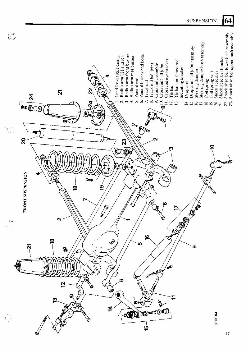
.. . . ,..: ~. .,”, :;.c ..., :.... .* .*-‘ ,.. ,
. .. . .
, ,. , .
in
17
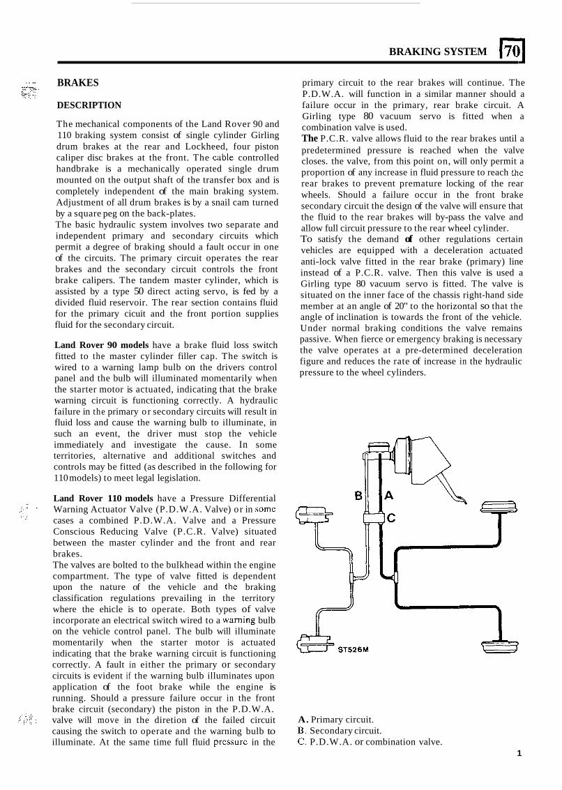
BRAKING SYSTEM
. . ... ,....... ... .. . ... ..>:. \., . . ., ._ : ?Y!:. .:.
BRAKES
DESCRIPTION
The mechanical components of the Land Rover 90 and 110 braking system consist of single cylinder Girling drum brakes at the rear and Lockheed, four piston caliper disc brakes at the front. The cable controlled handbrake is a mechanically operated single drum mounted on the output shaft of the transfer box and is completely independent of the main braking system. Adjustment of all drum brakes is by a snail cam turned by a square peg on the back-plates. The basic hydraulic system involves two separate and independent primary and secondary circuits which permit a degree of braking should a fault occur in one of the circuits. The primary circuit operates the rear brakes and the secondary circuit controls the front brake calipers. The tandem master cylinder, which is assisted by a type 50 direct acting servo, is fed by a divided fluid reservoir. The rear section contains fluid for the primary cicuit and the front portion supplies fluid for the secondary circuit.
Land Rover 90 models have a brake fluid loss switch fitted to the master cylinder filler cap. The switch is wired to a warning lamp bulb on the drivers control panel and the bulb will illuminated momentarily when the starter motor is actuated, indicating that the brake warning circuit is functioning correctly. A hydraulic failure in the primary or secondary circuits will result in fluid loss and cause the warning bulb to illuminate, in such an event, the driver must stop the vehicle immediately and investigate the cause. In some territories, alternative and additional switches and controls may be fitted (as described in the following for 110 models) to meet legal legislation.
Land Rover 110 models have a Pressure Differential Warning Actuator Valve (P.D.W.A. Valve) or in some cases a combined P.D.W.A. Valve and a Pressure Conscious Reducing Valve (P.C.R. Valve) situated between the master cylinder and the front and rear brakes. The valves are bolted to the bulkhead within the engine compartment. The type of valve fitted is dependent upon the nature of the vehicle and the braking classification regulations prevailing in the territory where the ehicle is to operate. Both types of valve incorporate an electrical switch wired to a warning bulb on the vehicle control panel. The bulb will illuminate momentarily when the starter motor is actuated indicating that the brake warning circuit is functioning correctly. A fault in either the primary or secondary circuits is evident if the warning bulb illuminates upon application of the foot brake while the engine is running. Should a pressure failure occur in the front brake circuit (secondary) the piston in the P.D.W.A. valve will move in the diretion of the failed circuit causing the switch to operate and the warning bulb to illuminate. At the same time full fluid prcssure in the
- .
primary circuit to the rear brakes will continue. The P.D.W.A. will function in a similar manner should a failure occur in the primary, rear brake circuit. A Girling type 80 vacuum servo is fitted when a combination valve is used. The P.C.R. valve allows fluid to the rear brakes until a predetermined pressure is reached when the valve closes. the valve, from this point on, will only permit a proportion of any increase in fluid pressure to reach the rear brakes to prevent premature locking of the rear wheels. Should a failure occur in the front brake secondary circuit the design of the valve will ensure that the fluid to the rear brakes will by-pass the valve and allow full circuit pressure to the rear wheel cylinder. To satisfy the demand of other regulations certain vehicles are equipped with a deceleration actuated anti-lock valve fitted in the rear brake (primary) line instead of a P.C.R. valve. Then this valve is used a Girling type 80 vacuum servo is fitted. The valve is situated on the inner face of the chassis right-hand side member at an angle of 20" to the horizontal so that the angle of inclination is towards the front of the vehicle. Under normal braking conditions the valve remains passive. When fierce or emergency braking is necessary the valve operates at a pre-determined deceleration figure and reduces the rate of increase in the hydraulic pressure to the wheel cylinders.
A. Primary circuit. B. Secondary circuit. C. P.D.W.A. or combination valve.
1
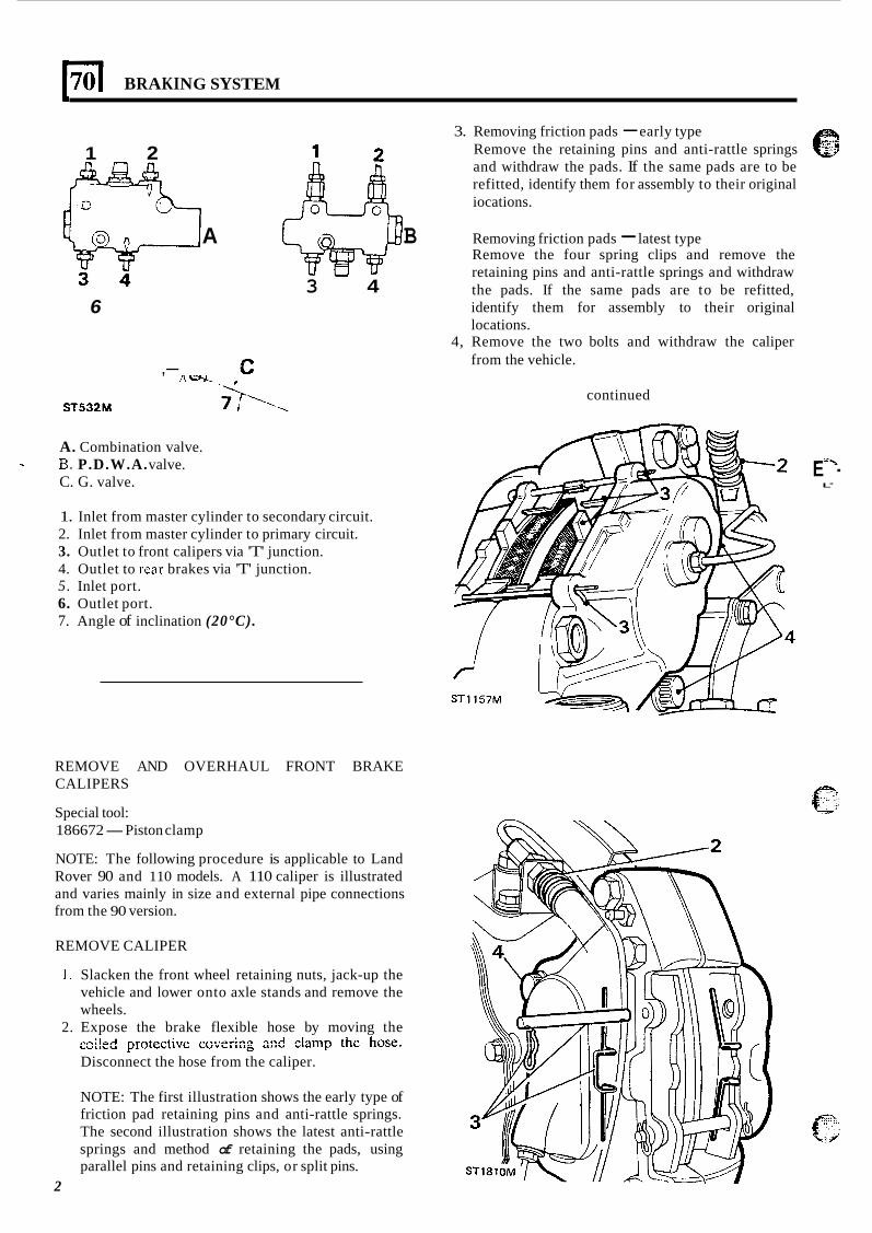
170 I BRAKING SYSTEM
3. Removing friction pads - early type Remove the retaining pins and anti-rattle springs and withdraw the pads. If the same pads are to be refitted, identify them for assembly to their original iocations.
1 2
A B Removing friction pads - latest type Remove the four spring clips and remove the retaining pins and anti-rattle springs and withdraw the pads. If the same pads are to be refitted, identify them for assembly to their original locations.
4, Remove the two bolts and withdraw the caliper from the vehicle.
3 4 6
,- continued
ST532M
A. Combination valve. B. P.D.W.A. valve. C. G. valve.
1. Inlet from master cylinder to secondary circuit. 2. Inlet from master cylinder to primary circuit. 3. Outlet to front calipers via 'T' junction. 4. Outlet to rcar brakes via 'T' junction. 5. Inlet port. 6. Outlet port. 7. Angle of inclination (20°C).
REMOVE AND OVERHAUL FRONT BRAKE CALIPERS
Special tool: 186672 -Piston clamp
NOTE: The following procedure is applicable to Land Rover 90 and 110 models. A 110 caliper is illustrated and varies mainly in size and external pipe connections from the 90 version.
REMOVE CALIPER
1. Slacken the front wheel retaining nuts, jack-up the vehicle and lower onto axle stands and remove the wheels.
2. Expose the brake flexible hose by moving the nn; I~r l m , n t n , - t ; . r a , - n s r a A n n q n A rlomn thn hnco L U L ' b " y 1 U k b b L n " b b U " b ' L I I ~ Ull" - . u n n m y % L . b . I "U I .
Disconnect the hose from the caliper.
NOTE: The first illustration shows the early type of friction pad retaining pins and anti-rattle springs. The second illustration shows the latest anti-rattle springs and method of retaining the pads, using parallel pins and retaining clips, or split pins.
2
/. -% E - L"
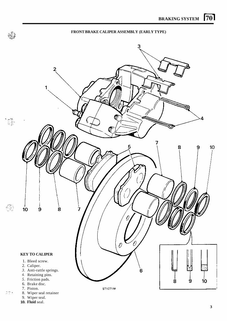
BRAKING SYSTEM 170 I
KEY TO CALIPER
1. Bleed screw. 2. Caliper. 3. Anti-rattle springs. 4. Retaining pins. 5. Friction pads. 6. Brake disc. 7. Piston. 8. Wiper seal retainer 9. Wiper seal.
?. "*, .? , *
10. Fluid seal.
FRONT BRAKE CALIPER ASSEMBLY (EARLY TYPE)
3
ST1271M 1
3
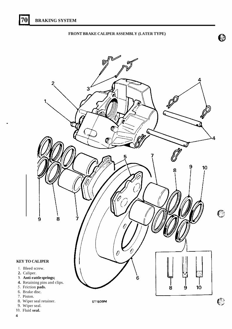
BRAKING SYSTEM
FRONT BRAKE CALIPER ASSEMBLY (LATER TYPE)
.
8
KEY TO CALIPER
1. Bleed screw. 2. Caliper.
4. Retaining pins and clips. 5 . Friction pads. 6. Brake disc. 7. Piston. 8. Wiper seal retainer. 9. Wiper seal.
3. Anti-rattle springs;
10. Fluid seal. 4
I ST1809M
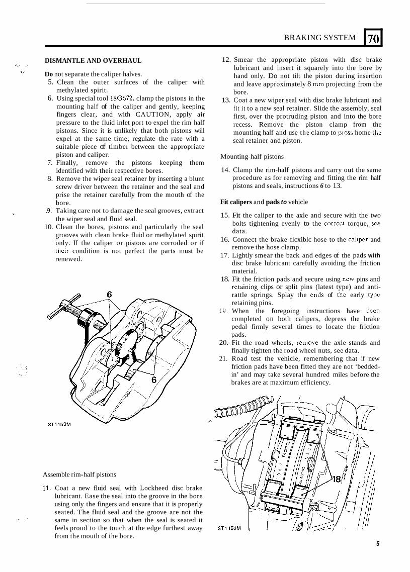
BRAKING SYSTEM
DISMANTLE AND OVERHAUL
Do not separate the caliper halves.
r : . . .I
s r .
5. Clean the outer surfaces of the caliper with methylated spirit.
6. Using special tool 18G672, clamp the pistons in the mounting half of the caliper and gently, keeping fingers clear, and with CAUTION, apply air pressure to the fluid inlet port to expel the rim half pistons. Since it is unlikely that both pistons will expel at the same time, regulate the rate with a suitable piece of timber between the appropriate piston and caliper.
7. Finally, remove the pistons keeping them identified with their respective bores.
8. Remove the wiper seal retainer by inserting a blunt screw driver between the retainer and the seal and prise the retainer carefully from the mouth of the bore.
9. Taking care not to damage the seal grooves, extract * the wiper seal and fluid seal. 10. Clean the bores, pistons and particularly the seal
grooves with clean brake fluid or methylated spirit only. If the caliper or pistons are corroded or if their condition is not perfect the parts must be renewed.
1
70
/-
Assemble rim-half pistons
11. Coat a new fluid seal with Lockheed disc brake lubricant. Ease the seal into the groove in the bore using only the fingers and ensure that it is properly seated. The fluid seal and the groove are not the same in section so that when the seal is seated it feels proud to the touch at the edge furthest away from the mouth of the bore.
. I*
12. Smear the appropriate piston with disc brake lubricant and insert it squarely into the bore by hand only. Do not tilt the piston during insertion and leave approximately 8 mm projecting from the bore.
13. Coat a new wiper seal with disc brake lubricant and fi t i t to a new seal retainer. Slide the assembly, seal first, over the protruding piston and into the bore recess. Remove the piston clamp from the mounting half and use the clamp to prcss home the seal retainer and piston.
Mounting-half pistons
14. Clamp the rim-half pistons and carry out the same procedure as for removing and fitting the rim half pistons and seals, instructions 6 to 13.
Fit calipers and pads to vehicle
15. Fit the caliper to the axle and secure with the two bolts tightening evenly to the correct torque, sce data.
16. Connect the brake flcxiblc hose to the calipcr and remove the hose clamp.
17. Lightly smear the back and edges of the pads with disc brake lubricant carefully avoiding the friction material.
18. Fit the friction pads and secure using ncw pins and rctaining clips or split pins (latest type) and anti- rattle springs. Splay the cnds of thc early typc retaining pins.
19. When the foregoing instructions have been completed on both calipers, depress the brake pedal firmly several times to locate the friction pads.
20. Fit the road wheels, rcmovc the axle stands and finally tighten the road wheel nuts, see data.
21. Road test the vehicle, remembering that if new friction pads have been fitted they are not ‘bedded- in’ and may take several hundred miles before the brakes are at maximum efficiency.
5
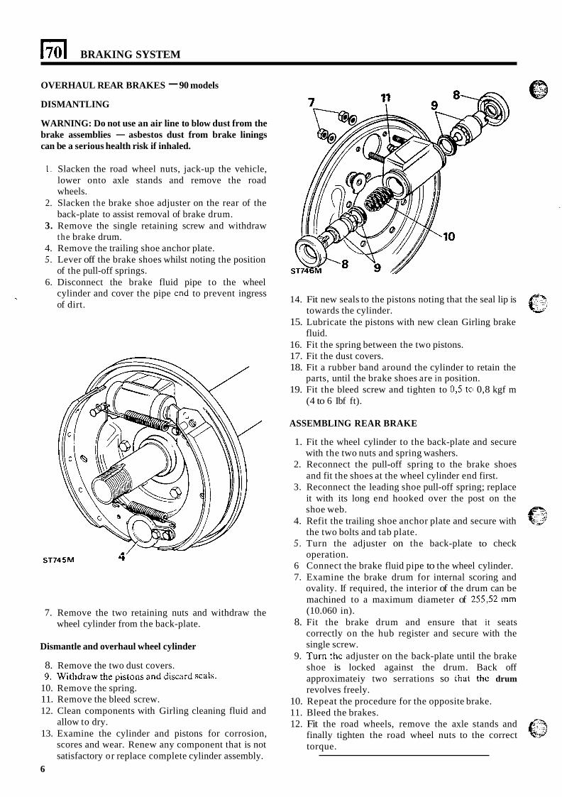
1701 BRAKING SYSTEM
OVERHAUL REAR BRAKES - 90 models
DISMANTLING
WARNING: Do not use an air line to blow dust from the brake assemblies - asbestos dust from brake linings can be a serious health risk if inhaled.
1. Slacken the road wheel nuts, jack-up the vehicle, lower onto axle stands and remove the road wheels.
2. Slacken the brake shoe adjuster on the rear of the back-plate to assist removal of brake drum.
3. Remove the single retaining screw and withdraw the brake drum.
4. Remove the trailing shoe anchor plate. 5. Lever off the brake shoes whilst noting the position
of the pull-off springs. 6. Disconnect the brake fluid pipe to the wheel
cylinder and cover the pipe end to prevent ingress of dirt.
ST745M 4
7. Remove the two retaining nuts and withdraw the wheel cylinder from the back-plate.
Dismantle and overhaul wheel cylinder
8. Remove the two dust covers. 9. yqithdra.w tiie pistoiis arid discard
10. Remove the spring. 11. Remove the bleed screw. 12. Clean components with Girling cleaning fluid and
allow to dry. 13. Examine the cylinder and pistons for corrosion,
scores and wear. Renew any component that is not satisfactory or replace complete cylinder assembly.
6
14. Fit new seals to the pistons noting that the seal lip is
15. Lubricate the pistons with new clean Girling brake
16. Fit the spring between the two pistons. 17. Fit the dust covers. 18. Fit a rubber band around the cylinder to retain the
19. Fit the bleed screw and tighten to 0,5 to 0,8 kgf m
towards the cylinder.
fluid.
parts, until the brake shoes are in position.
(4 to 6 Ibf ft).
ASSEMBLING REAR BRAKE
1. Fit the wheel cylinder to the back-plate and secure with the two nuts and spring washers.
2. Reconnect the pull-off spring to the brake shoes and fit the shoes at the wheel cylinder end first.
3. Reconnect the leading shoe pull-off spring; replace it with its long end hooked over the post on the shoe web.
4. Refit the trailing shoe anchor plate and secure with the two bolts and tab plate.
5 . Turn the adjuster on the back-plate to check operation.
6 Connect the brake fluid pipe to the wheel cylinder. 7. Examine the brake drum for internal scoring and
ovality. If required, the interior of the drum can be machined to a maximum diameter of 255,52 mm (10.060 in).
8. Fit the brake drum and ensure that it seats correctly on the hub register and secure with the single screw.
9. Turn the adjuster on the back-plate until the brake shoe is locked against the drum. Back off approximateiy two serrations so [hat the drum revolves freely.
10. Repeat the procedure for the opposite brake. 11. Bleed the brakes. 12. Fit the road wheels, remove the axle stands and
finally tighten the road wheel nuts to the correct torque.
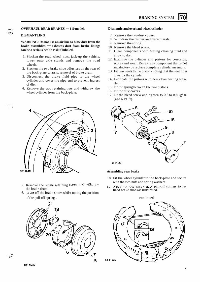
BRAKING SYSTEM
i' I .,.. yr.::: ' --r ..I OVERHAUL REAR BRAKES - 110 models
DISMANTLING
WARNING: Do not use an air line to blow dust from the brake assemblies - asbestos dust from brake linings can be a serious health risk if inhaled.
:.:::f!,. , ... iy .,> ..., .. . .
1. Slacken the road wheel nuts, jack-up the vehicle, lower onto axle stands and remove the road wheels.
2. Slacken the two brake shoe adjusters on the rear of the back-plate to assist removal of brake drum.
3. Disconnect the brake fluid pipe to the wheel cylinder and cover the pipe end to prevent ingress of dirt.
4. Remove the two retaining nuts and withdraw the wheel cylinder from the back-plate.
ST
Dismantle and overhaul wheel cylinder
7. Remove the two dust covers. 8. Withdraw the pistons and discard seals. 9. Removc the spring.
10. Remove the bleed screw. 11. Clean components with Girling cleaning fluid and
allow to dry. 12. Examine the cylinder and pistons for corrosion,
scores and wear. Renew any component that is not satisfactory or replace complete cylinder assembly.
13. Fit new seals to the pistons noting that the seal lip is towards the cylinder.
14. Lubricate the pistons with new clean Girling brake fluid.
15. Fit the spring between the two pistons. 16. Fit the dust covers. 17. Fit the bleed screw and tighten to 0,5 to 0,8 kgf m
(4 to 6 Ibf ft).
7
ST619M
Assembling rear brake
18. Fit the wheel cylinder to the back-plate and secure
19. Assemble new brake shoe pull-off springs to re- with the two nuts and spring washers.
lined brake shoes as illustrated. 5. Remove the single retaining Screw and withdraw
6. Lever off the brake shoes whilst noting the position the brake drum.
of the pull-off springs. continued
5 ST 1
STl165M 7
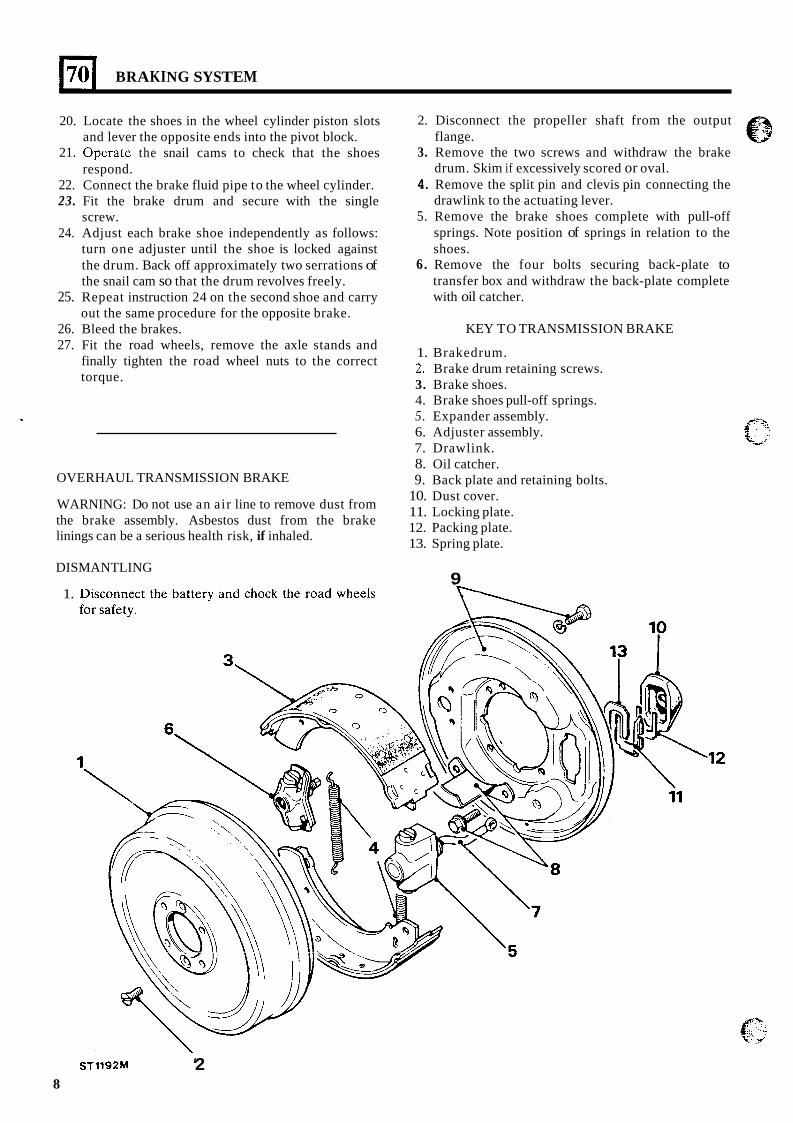
1701 BRAKING SYSTEM
20.
21.
Locate the shoes in the wheel cylinder piston slots and lever the opposite ends into the pivot block. Operatc the snail cams to check that the shoes respond.
22. Connect the brake fluid pipe to the wheel cylinder. 23. Fit the brake drum and secure with the single
screw. 24. Adjust each brake shoe independently as follows:
turn one adjuster until the shoe is locked against the drum. Back off approximately two serrations of the snail cam so that the drum revolves freely.
25. Repeat instruction 24 on the second shoe and carry out the same procedure for the opposite brake.
26. Bleed the brakes. 27. Fit the road wheels, remove the axle stands and
finally tighten the road wheel nuts to the correct torque.
OVERHAUL TRANSMISSION BRAKE
WARNING: Do not use an air line to remove dust from the brake assembly. Asbestos dust from the brake linings can be a serious health risk, if inhaled.
DISMANTLING
1.
2. Disconnect the propeller shaft from the output flange.
3. Remove the two screws and withdraw the brake drum. Skim if excessively scored or oval.
4. Remove the split pin and clevis pin connecting the drawlink to the actuating lever.
5. Remove the brake shoes complete with pull-off springs. Note position of springs in relation to the shoes.
6. Remove the four bolts securing back-plate to transfer box and withdraw the back-plate complete with oil catcher.
KEY TO TRANSMISSION BRAKE
1. Brakedrum. 2. Brake drum retaining screws. 3. Brake shoes. 4. Brake shoes pull-off springs. 5. Expander assembly. 6. Adjuster assembly. 7. Drawlink. 8. Oil catcher. 9. Back plate and retaining bolts.
10. Dust cover. 11. Locking plate. 12. Packing plate. 13. Spring plate.
9
ST1192M ‘2 8
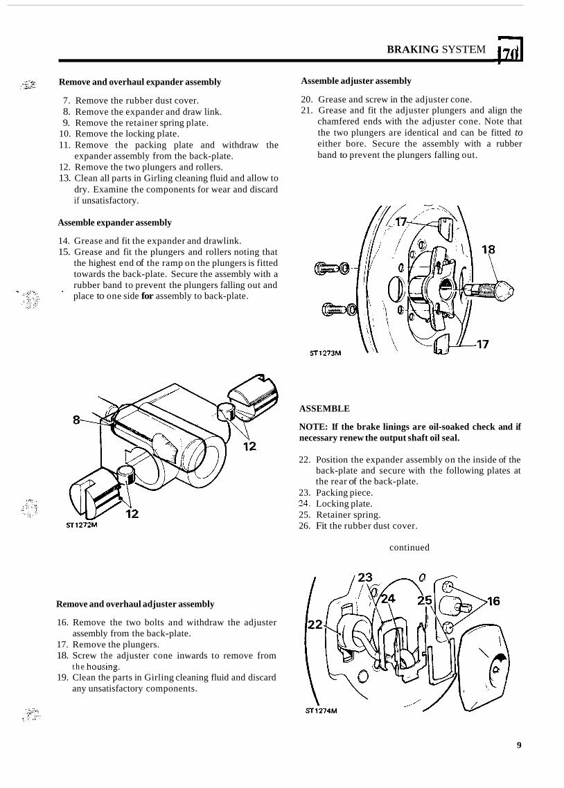
BRAKING SYSTEM 170
Remove and overhaul expander assembly
7. Remove the rubber dust cover. 8. Remove the expander and draw link. 9. Remove the retainer spring plate.
10. Remove the locking plate. 11. Remove the packing plate and withdraw the
12. Remove the two plungers and rollers. 13. Clean all parts in Girling cleaning fluid and allow to
dry. Examine the components for wear and discard if unsatisfactory.
expander assembly from the back-plate.
Assemble expander assembly
14. Grease and fit the expander and drawlink. 15. Grease and fit the plungers and rollers noting that
the highest end of the ramp on the plungers is fitted towards the back-plate. Secure the assembly with a rubber band to prevent the plungers falling out and place to one side for assembly to back-plate. -
-127%
Remove and overhaul adjuster assembly
16. Remove the two bolts and withdraw the adjuster
17. Remove the plungers. 18. Screw the adjuster cone inwards to remove from
19. Clean the parts in Girling cleaning fluid and discard
assembly from the back-plate.
t h e housing.
any unsatisfactory components.
Assemble adjuster assembly
20. Grease and screw in the adjuster cone. 21. Grease and fit the adjuster plungers and align the
chamfered ends with the adjuster cone. Note that the two plungers are identical and can be fitted to either bore. Secure the assembly with a rubber band to prevent the plungers falling out.
ASSEMBLE
NOTE: If the brake linings are oil-soaked check and if necessary renew the output shaft oil seal.
22. Position the expander assembly on the inside of the back-plate and secure with the following plates at the rear of the back-plate.
23. Packing piece. 24. Locking plate. 25. Retainer spring. 26. Fit the rubber dust cover.
continued
' :..::d. . . .. , .. . ... . , .. . , > ,. ,., ...,. . ..
9
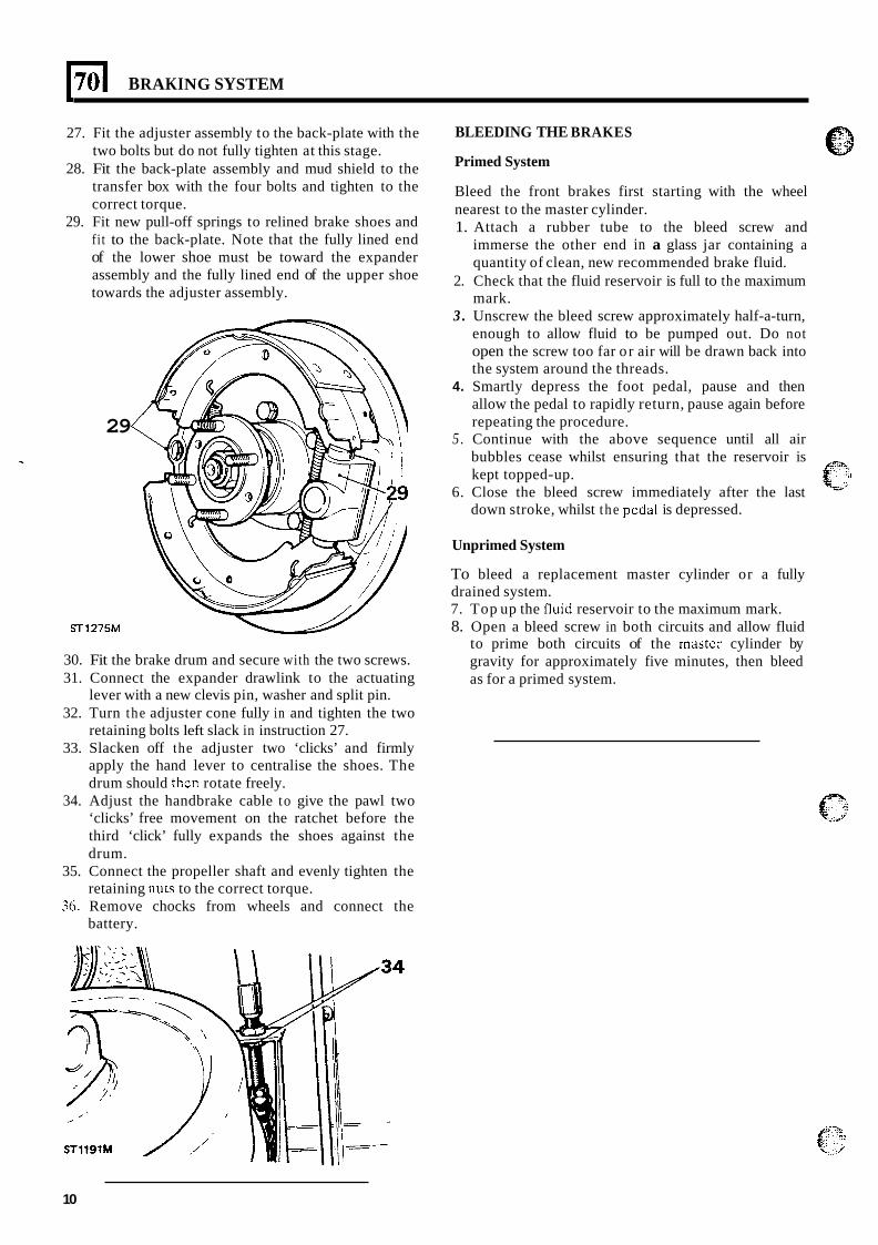
1701 BRAKING SYSTEM
27. Fit the adjuster assembly to the back-plate with the two bolts but do not fully tighten at this stage.
28. Fit the back-plate assembly and mud shield to the transfer box with the four bolts and tighten to the correct torque.
29. Fit new pull-off springs to relined brake shoes and fit to the back-plate. Note that the fully lined end of the lower shoe must be toward the expander assembly and the fully lined end of the upper shoe towards the adjuster assembly.
29
ST1275M
30. Fit the brake drum and secure with the two screws. 31. Connect the expander drawlink to the actuating
lever with a new clevis pin, washer and split pin. 32. Turn the adjuster cone fully in and tighten the two
retaining bolts left slack in instruction 27. 33. Slacken off the adjuster two ‘clicks’ and firmly
apply the hand lever to centralise the shoes. The drum should then rotate freely.
34. Adjust the handbrake cable to give the pawl two ‘clicks’ free movement on the ratchet before the third ‘click’ fully expands the shoes against the drum.
35. Connect the propeller shaft and evenly tighten the retaining nuts to the correct torque.
36. Remove chocks from wheels and connect the battery.
BLEEDING THE BRAKES
Primed System
Bleed the front brakes first starting with the wheel nearest to the master cylinder. 1. Attach a rubber tube to the bleed screw and
immerse the other end in a glass jar containing a quantity of clean, new recommended brake fluid.
2. Check that the fluid reservoir is full to the maximum mark.
3 . Unscrew the bleed screw approximately half-a-turn, enough to allow fluid to be pumped out. Do not open the screw too far or air will be drawn back into the system around the threads.
4. Smartly depress the foot pedal, pause and then allow the pedal to rapidly return, pause again before repeating the procedure.
5 . Continue with the above sequence until all air bubbles cease whilst ensuring that the reservoir is kept topped-up.
6. Close the bleed screw immediately after the last down stroke, whilst the pedal is depressed.
Unprimed System
To bleed a replacement master cylinder or a fully drained system. 7. Top up the fluid reservoir to the maximum mark. 8. Open a bleed screw in both circuits and allow fluid
to prime both circuits of the mastcr cylinder by gravity for approximately five minutes, then bleed as for a primed system.
10
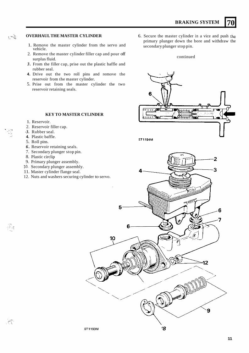
BRAKING SYSTEM
6. Secure the master cylinder in a vice and push the primary plunger down the bore and withdraw the secondary plunger stop pin.
- , I” . _-_ OVERHAUL THE MASTER CYLINDER . _ I,,
1. Remove the master cylinder from the servo and vehicle.
70
continued 2. Remove the master cylinder filler cap and pour off
3 . From the filler cap, prise out the plastic baffle and
4. Drive out the two roll pins and remove the
5. Prise out from the master cylinder the two
surplus fluid.
rubber seal.
reservoir from the master cylinder.
reservoir retaining seals.
KEY TO MASTER CYLINDER
1. Reservoir. 2. Reservoir filler cap.
-3. Rubber seal. 4. Plastic baffle. 5. Roll pins. 6 . Reservoir retaining seals. 7. Secondary plunger stop pin. 8. Plastic circlip 9. Primary plunger assembly.
10. Secondary plunger assembly. 11. Master cylinder flange seal. 12. Nuts and washers securing cylinder to servo.
STllS4M
. . . . ..., <,:: , . . . , ..
STl193M ‘8
11
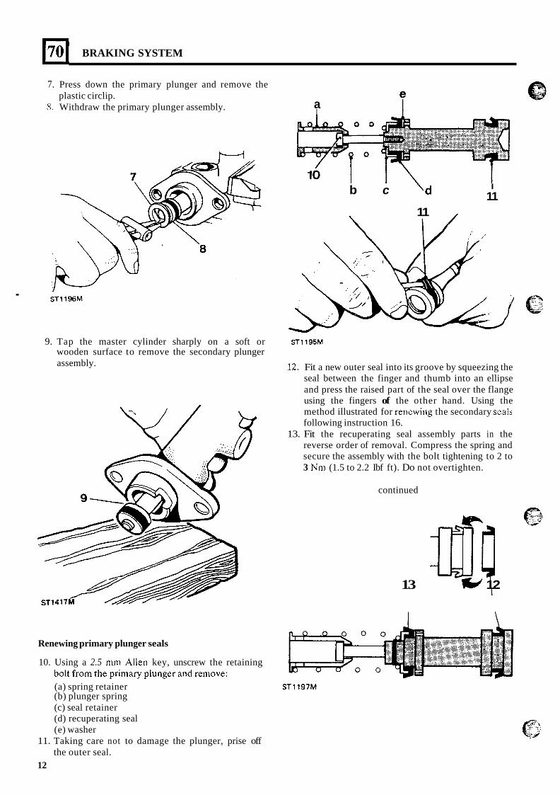
BRAKING SYSTEM
7. Press down the primary plunger and remove the
8. Withdraw the primary plunger assembly. plastic circlip.
a I
.
I 11 b c
11 I
9. Tap the master cylinder sharply on a soft or ST1195M wooden surface to remove the secondary plunger assembly. 12. Fit a new outer seal into its groove by squeezing the
seal between the finger and thumb into an ellipse and press the raised part of the seal over the flange using the fingers of the other hand. Using the method illustrated for rencwing the secondary scals following instruction 16.
13. Fit the recuperating seal assembly parts in the reverse order of removal. Compress the spring and secure the assembly with the bolt tightening to 2 to 3 Nm (1.5 to 2.2 Ibf ft). Do not overtighten.
continued
f-8 .... +.&*
13 a! 12
Renewing primary plunger seals
10. Using a 2.5 mm Allen key, unscrew the retaining hAlt F,,, th- -,;-,,., -I, .-*-- ,-A -n-,.IY. U U L L L I U I I I LILL pi i i i ia iy piuiifjb~ aiiu ILIIIUVL.
(a) spring retainer ST1197M (b) plunger spring (c) seal retainer (d) recuperating seal (e) washer
the outer seal. 11. Taking care not to damage the plunger, prise off
12
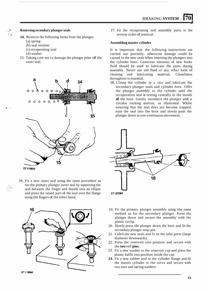
BRAKING SYSTEM I70 I
.. ,. Renewing secondary plunger seals
14. Remove the following items from the plunger: f ,*:
(a) spring (b) seal retainer (c) recuperating seal (d) washer
outer seal. 15. Taking care not to damage the plunger prise off the
a \ b d 14 \ I I
. :: I C
I I
15
ST1198M
16. Fit a new outer seal using the same procedure as for the primary plunger outer seal by squeezing the seal between the finger and thumb into an ellipse and press the raised part of the seal over the flange using the fingers of the other hand.
17. Fit the recuperating seal assembly parts in the reverse order of removal.
Assembling master cylinder
It is important that the following instructions are carried out precisely, otherwise damage could be caused to the new seals when inserting the plungers into the cylinder bore. Generous amounts of new brake fluid should be used to lubricate the parts during assembly. Never use old fluid or any other form of cleaning and lubricating material. Cleanliness throughout is essential. 18. Clamp the cylinder in a vice and lubricate the
secondary plunger seals and cylinder bore. Offer the plunger assembly to the cylinder until the recuperation seal is resting centrally in the mouth of the bore. Gently introduce the plunger with a circular rocking motion, as illustrated. Whilst ensuring that the seal does not become trapped, ease the seal into the bore and slowly push the plunger down in one continuous movement.
-k ss.
I I 18
ST 1 ZOOM
19.
20.
21.
22.
23.
24.
Fit the primary plunger assembly using the same method as for the secondary plunger. Press the plunger down and secure the assembly with the plastic circlip. Slowly press the plunger down the bore and fit the secondary plunger stop-pin. Lubricate new seals and fit to the inlet ports (large diameter downwards). Press the reservoir into position and secure with the two m!I pins. Fit a new washer to the reservoir cap and press the plastic baffle into position inside the cap. Fit a new rubber seal to the cylinder flange and fit the master cylinder to the servo and secure with two nuts and spring washers.
S T 1 1 9 9 M
13
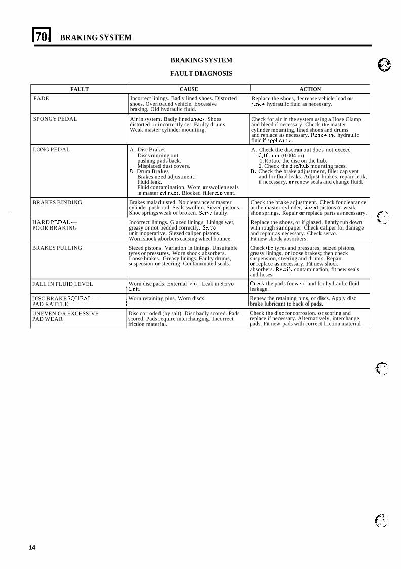
BRAKING SYSTEM
Incorrect linings. Badly lined shoes. Distorted shoes. Overloaded vehicle. Excessive braking. Old hydraulic fluid.
BRAKING SYSTEM
FAULT DIAGNOSIS
Replace the shoes, decrease vehicle load or renew hydraulic fluid as necessary.
FAULT I CAUSE I ACTION
Air in system. Badly lined shoes. Shoes distorted or incorrectly set. Faulty drums. Weak master cylinder mounting.
FADE
Check for air in the system using a Hose Clamp and bleed if necessary. Check the master cylinder mounting, lined shoes and drums and replace as necessary. Renew the hydraulic fluid if appkdblc.
Brakes maladjusted. No clearance at master cylinder push rod. Seals swollen. Siezed pistons. Shoe springs weak or broken. Servo faulty.
SPONGY PEDAL
Check the brake adjustment. Check for clearance at the master cylinder, siezcd pistons or weak shoe springs. Repair or replace parts as necessary.
HARD PEDAL- POOR BRAKING
BRAKES PULLING
FALL IN FLUID LEVEL
LONG PEDAL
Incorrect linings. Glazed linings. Linings wet, greasy or not bedded correctly. Servo unit inoperative. Siezed caliper pistons. Worn shock aborbers causing wheel bounce.
Siezed pistons. Variation in linings. Unsuitable tyres or pressures. Worn shock absorbers. Loose brakes. Greasy linings. Faulty drums, suspension or steering. Contaminated seals.
Replace the shoes, or if glazed, lightly rub down with rough sandpaper. Check caliper for damage and repair as necessary. Check servo. Fit new shock absorbers.
Check thc tyres and pressures, seized pistons, greasy linings, or loose brakes; then check suspension, steering and drums. Repair or replace as necessary. Fit new shock absorbers. Recti@ contamination, fit new seals and hoses.
Chcck the pads for wcar and for hydraulic fluid Worn disc pads. External leak. Leak in Scrvo
A. Disc Brakes Discs running out pushing pads back. Misplaced dust covers.
B. Drum Brakes Brakes need adjustment. Fluid leak. Fluid contamination. Wom or swollen seals in master cvlinder. Blocked filler caD vent.
~~~~~~~~~ ~
UNEVEN OR EXCESSIVE PAD WEAR
A. Check the disc run out does not exceed 0,lO mm (0.004 in) 1. Rotate the disc on the hub. 2. Check the d i d h u b mounting faces.
and for fluid leaks. Adjust brakes, repair leak, if necessary, or renew seals and change fluid.
B. Check the brake adjustment, filler cap vent
Disc corroded (by salt). Disc badly scored. Pads scored. Pads require interchanging. Incorrect friction material.
Check the disc for corrosion. or scoring and replace if necessary. Alternatively, interchange pads. Fit new pads with correct friction material.
BRAKES BINDING
1 Unit. I leakage.
DISC BRAKE SQUEAL- PAD RATTLE
1 Worn retaining pins. Worn discs. Renew the retaining pins, or discs. Apply disc I brake lubricant to back of pads.
14

~ . . .:...:;, :
. . 1 . ... ... ":)
.I..... ..l.l. . . . . ,.. , .
.....,. I . ; ... , . .
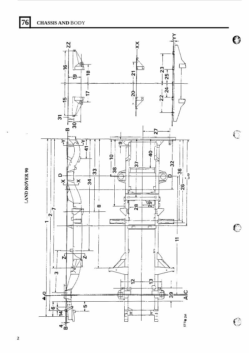
76
c 8
-
CHASSIS AND BODY
7-
2 m m
D 3
2
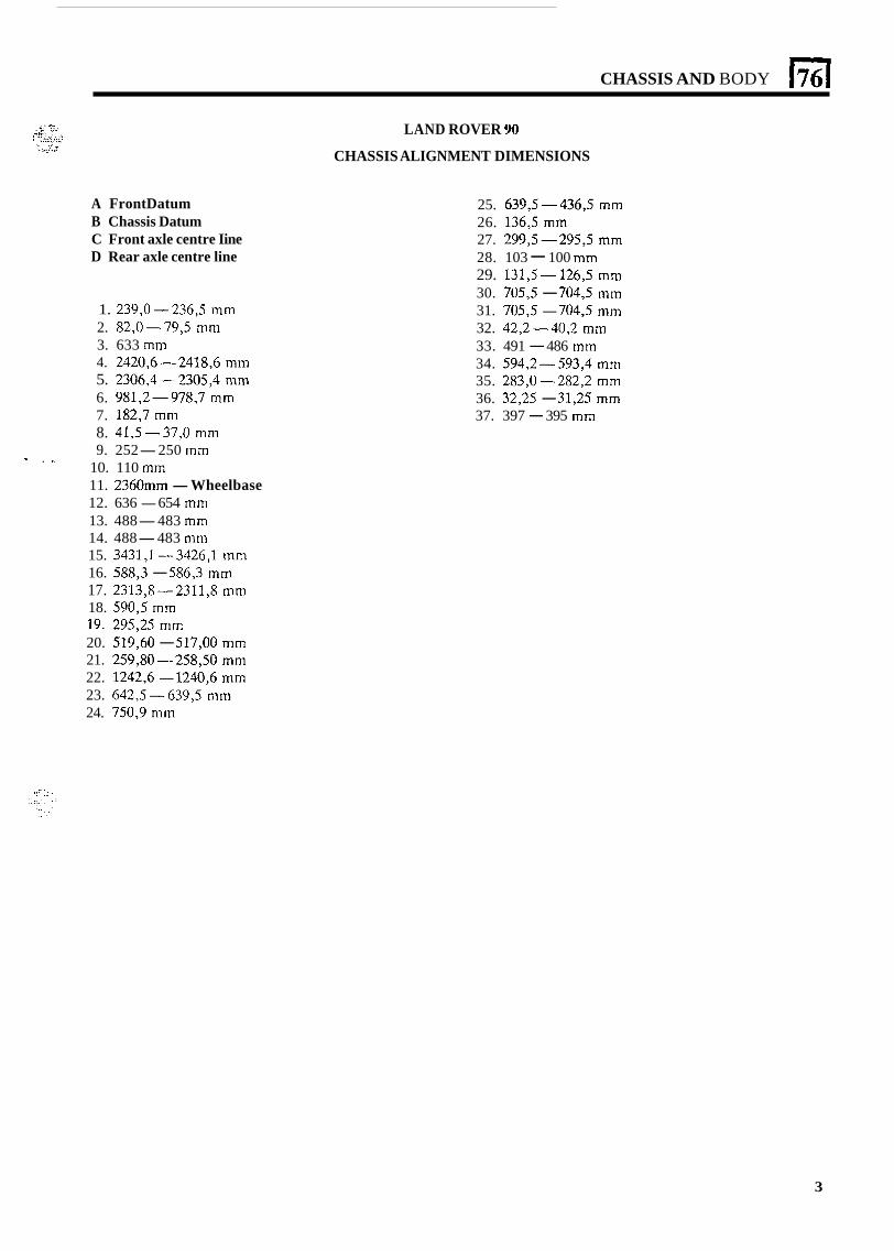
CHASSIS AND BODY
A FrontDatum B Chassis Datum C Front axle centre Iine D Rear axle centre line
1. 239,O-236,5 mm 2. 82,O-79,5 mm 3. 633 mm 4. 2420,6-2418,6 mm 5. 2306,4-2305,4 mm 6. 981,2-978,7 mm 7. 182,7 mm 8. 41,5-37,O mm 9. 252-250 mm - . ..
10. 110 mm 11. 2360" -Wheelbase 12. 636 - 654 mm 13. 488-483 mm 14. 488-483 mm 15. 3431,l-3426,l mm 16. 588,3 - 586,3 mm 17. 2313,8-2311,8 mm 18. 590,5 mm 19. 295,25 mm 20. 519,60 - 517,OO mm 21. 259,80-258,50 mm 22. 1242,6 - 1240,6 mm 23. 6423-66393 mm 24. 750,9 mm
LAND ROVER 90
CHASSIS ALIGNMENT DIMENSIONS
25. 639,5-436,5 mm 26. 136,5 mm 27. 299,5-295,5 mm 28. 103 - 100 mm 29. 131,5-- 126,5 mm 30. 7053 - 7043 mm 31. 7053 - 7043 mm 32. 42,2-40,2 mm 33. 491 - 486 mm 34. 594,2-593,4 mm 35. 283,O-2282,2 mm 36. 32,25 - 31,25 mm 37. 397 - 395 mm
3
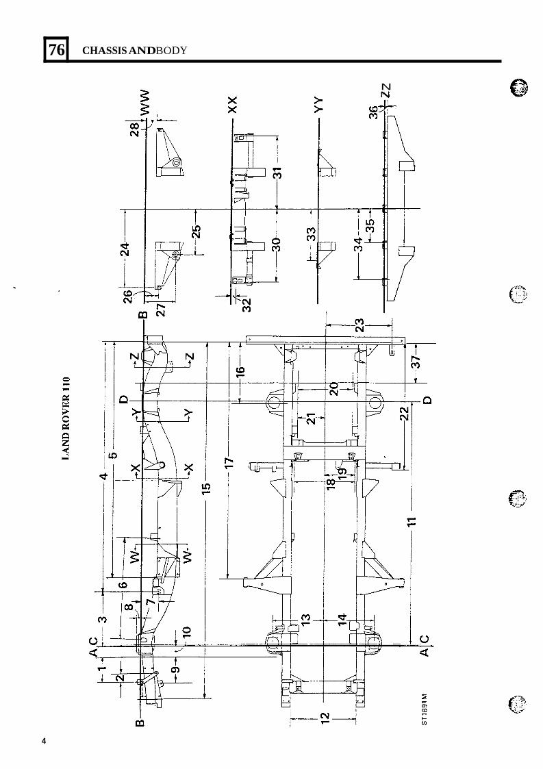
76
N
CHASSIS AND BODY
p i
I a 4
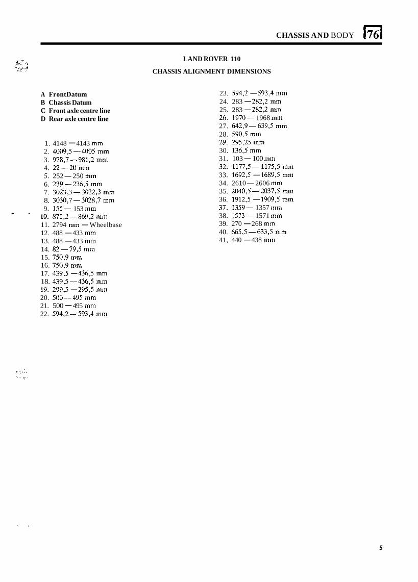
CHASSIS AND BODY El .. . . .... r”,,.. ’: ., , . :I 4.:: : . ... . ~ .
A FrontDatum B Chassis Datum C Front axle centre line D Rear axle centre line
1. 4148 - 4143 mm 2. 40093-4005 mm 3. 978,7-981,2 mm 4. 22-20” 5. 252-250 mm 6. 239-236,5 mm 7. 3023,3-3022,3 mm 8. 3030,7-3028,7 mm 9. 155- 153 mm
10. 871,2-869,2 mm 11. 2794 mm - Wheelbase 12. 488 - 433 mm 13. 488 - 433 mm 14. 82-79,5 mm 15. 750,9 mm 16. 750,9 mm 17. 4393 - 4363 mm 18. 4393 -4363 mm 19. 2993 - 2953 mm 20. 500-495 mm 21. 500 - 495 mm 22. 594,2-593,4 mm
- -
LAND ROVER 110
CHASSIS ALIGNMENT DIMENSIONS
23. 594,2 - 593,4 mm 24. 283 - 282,2 mm 25. 283 - 282,2 mm 26. 1970- 1968 mm 27. 642,9-639,5 mm 28. 590,5 mm 29. 295,25 mm 30. 136,5 mm 31. 103 - 100 mm 32. 1177,5- 1175,5 mm 33. 1692,5 - 1689,5 mm 34. 2610-2606 mm 35. 2040,5 -2037,5 mm 36. 1912,5 - 1909,5 mm 37. 1359- 1357 mm 38. 1573- 1571 mm 39. 270 - 268 mm 40. 665,5-633,5 mm 41, 440 - 438 mm
I. .
5

.
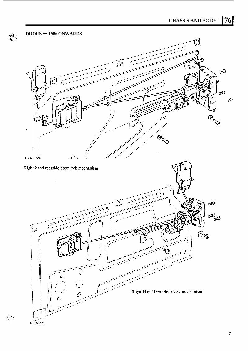
CHASSIS AND BODY 1761
DOORS - 1986 ONWARDS
7
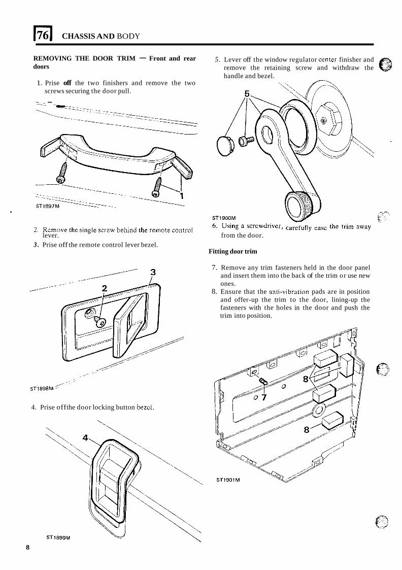
176 I CHASSIS AND BODY
REMOVING THE DOOR TRIM - Front and rear doors
1. Prise off the two finishers and remove the two screws securing the door pull.
-. -- .___ - ...- . 1.
5. Lever off the window regulator center finisher and remove the retaining screw and withdraw the handle and bezel.
2 . Remove the single Screw behind the remote control 6- Using a screwdriver, the trim away lever. from the door.
3 . Prise off the remote control lever bezel. Fitting door trim
7. Remove any trim fasteners held in the door panel and insert them into the back of the trim or use new ones.
8. Ensure that the anti-vibration pads are in position and offer-up the trim to the door, lining-up the fasteners with the holes in the door and push the trim into position.
4. Prise off the door locking button bezci.
',
8
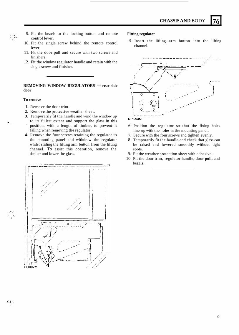
CHASSIS AND BODY
. I . ,. 9. Fit the bezels to the locking button and remote
10. Fit the single screw behind the remote control
11. Fit the door pull and secure with two screws and
12. Fit the window regulator handle and retain with the
control lever.
lever.
finishers.
single screw and finisher.
, ~ .. I. I
76
REMOVING WINDOW REGULATORS - rear side door
Fitting regulator
channel. 5. Insert the lifting arm button into the lifting
To remove
1. Remove the door trim. 2. Remove the protective weather sheet. 3. Temporarily fit the handle and wind the window up
position, with a length of timber, to prevent it falling when removing the regulator.
4. Remove the four screws retaining the regulator to the mounting panel and withdraw the regulator whilst sliding the lifting arm button from the lifting channel. To assist this operation, remove the timber and lower the glass.
. - to its fullest extent and support the glass in this
r-----.-----. - -1
c-- --- -/-- ST1903M
6. Position the regulator so that the fixing holes line-up with the holes in the mounting panel.
7. Secure with the four screws and tighten evenly. 8. Temporarily fit the handle and check that glass can
be raised and lowered smoothly without tight spots.
9. Fit the weather protection sheet with adhesive. 10. Fit the door trim, regulator handle, door pull, and
bezels.
9
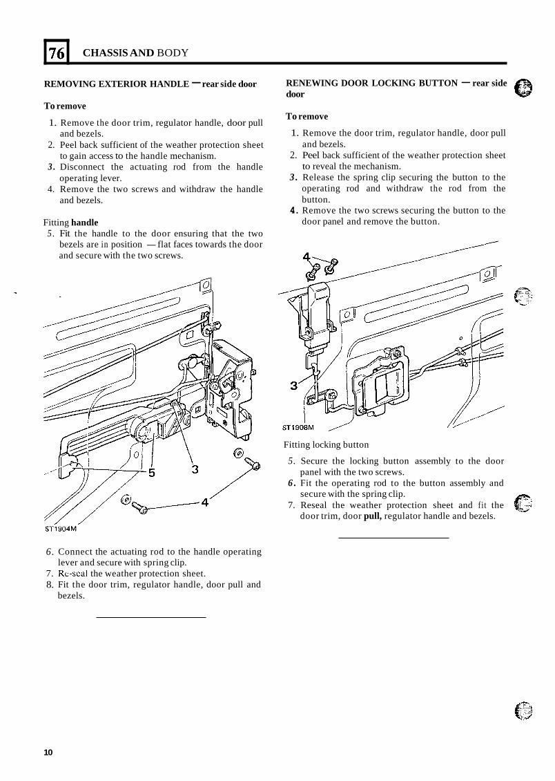
76
REMOVING EXTERIOR HANDLE - rear side door
CHASSIS AND BODY
To remove
1. Remove the door trim, regulator handle, door pull and bezels.
2. Peel back sufficient of the weather protection sheet to gain access to the handle mechanism.
3 . Disconnect the actuating rod from the handle operating lever.
4. Remove the two screws and withdraw the handle and bezels.
Fitting handle 5 . Fit the handle to the door ensuring that the two
bezels are in position - flat faces towards the door and secure with the two screws.
STi904M’
6.
7. 8.
Connect the actuating rod to the handle operating lever and secure with spring clip. Re-scal the weather protection sheet. Fit the door trim, regulator handle, door pull and bezels.
RENEWING DOOR LOCKING BUTTON - rear side door
To remove
1. Remove the door trim, regulator handle, door pull and bezels.
2. Peel back sufficient of the weather protection sheet to reveal the mechanism.
3 . Release the spring clip securing the button to the operating rod and withdraw the rod from the button.
4. Remove the two screws securing the button to the door panel and remove the button.
Fitting locking button
5. Secure the locking button assembly to the door panel with the two screws.
6 . Fit the operating rod to the button assembly and secure with the spring clip.
7. Reseal the weather protection sheet and fit the door trim, door pull, regulator handle and bezels.
10
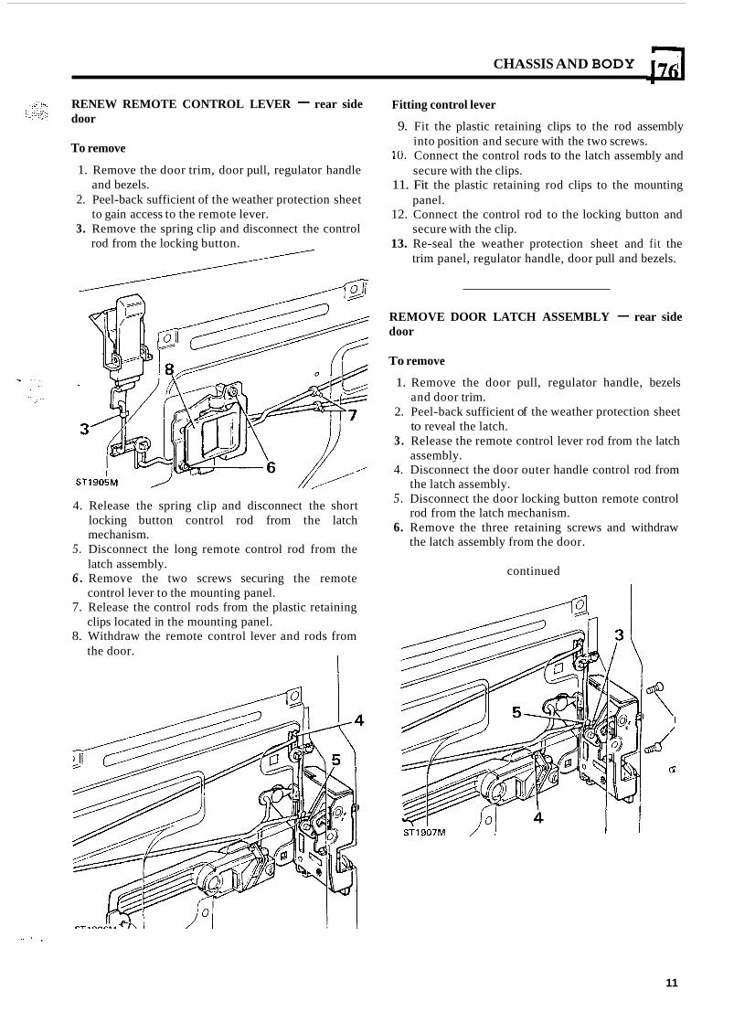
CHASSIS AND BODY 176 RENEW REMOTE CONTROL LEVER - rear side door
To remove
1. Remove the door trim, door pull, regulator handle
2. Peel-back sufficient of the weather protection sheet
3. Remove the spring clip and disconnect the control
and bezels.
to gain access to the remote lever.
rod from the locking button.
Fitting control lever
9. Fit the plastic retaining clips to the rod assembly
10. Connect the control rods to the latch assembly and
11. Fit the plastic retaining rod clips to the mounting
12. Connect the control rod to the locking button and
13. Re-seal the weather protection sheet and fit the
into position and secure with the two screws.
secure with the clips.
panel.
secure with the clip.
trim panel, regulator handle, door pull and bezels.
REMOVE DOOR LATCH ASSEMBLY - rear side door
To remove
1. Remove the door pull, regulator handle, bezels
2. Peel-back sufficient of the weather protection sheet
3. Release the remote control lever rod from the latch
4. Disconnect the door outer handle control rod from
and door trim.
to reveal the latch.
assembly.
the latch assembly. 5. Disconnect the door locking button remote control
6. Remove the three retaining screws and withdraw
4. Release the spring clip and disconnect the short locking button control rod from the latch mechanism.
5. Disconnect the long remote control rod from the latch assembly.
6 . Remove the two screws securing the remote control lever to the mounting panel.
7. Release the control rods from the plastic retaining clips located in the mounting panel.
8. Withdraw the remote control lever and rods from the door.
rod from the latch mechanism.
the latch assembly from the door.
continued
S I ’ ,
11
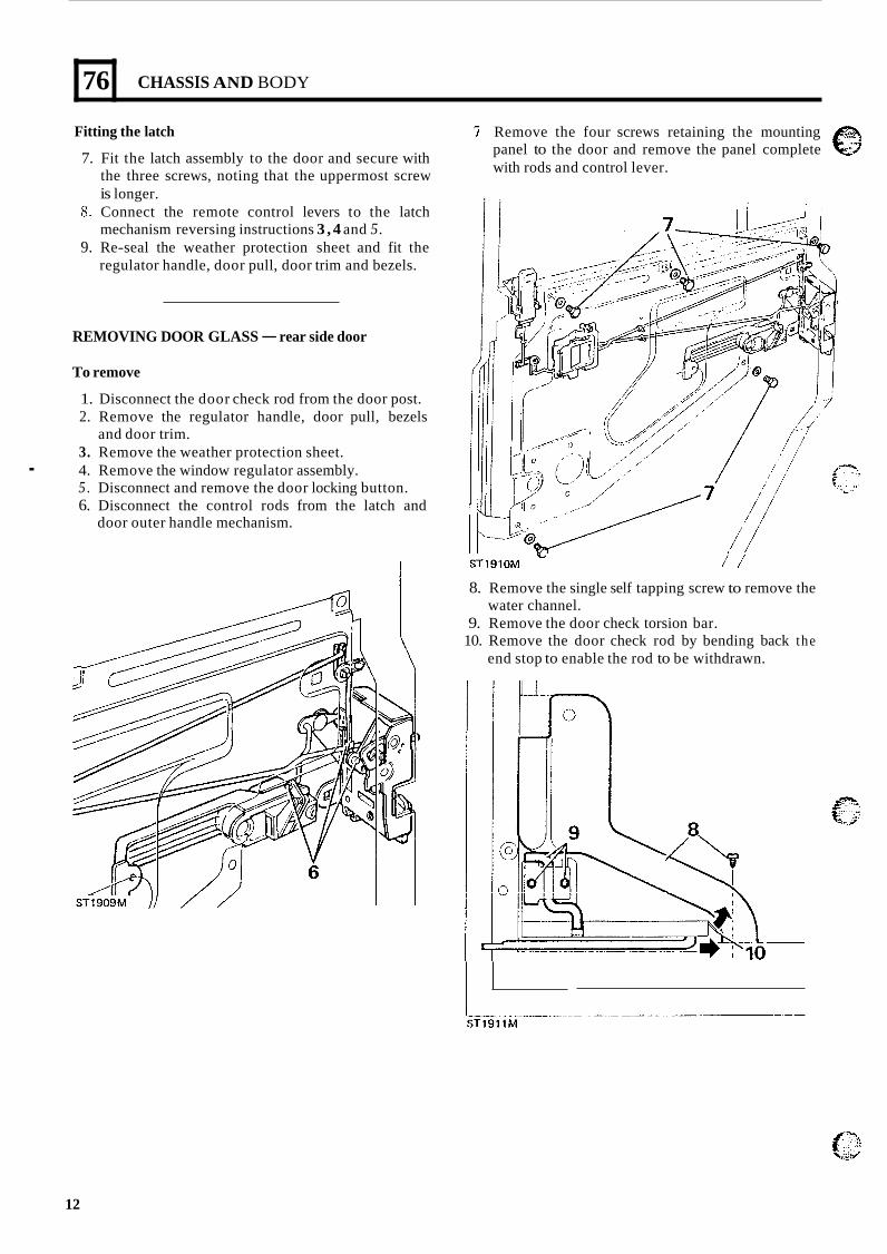
76
Fitting the latch
7. Fit the latch assembly to the door and secure with the three screws, noting that the uppermost screw is longer.
8. Connect the remote control levers to the latch mechanism reversing instructions 3 , 4 and 5.
9. Re-seal the weather protection sheet and fit the regulator handle, door pull, door trim and bezels.
CHASSIS AND BODY
REMOVING DOOR GLASS - rear side door
To remove
1. Disconnect the door check rod from the door post. 2. Remove the regulator handle, door pull, bezels
3. Remove the weather protection sheet.
5 . Disconnect and remove the door locking button. 6. Disconnect the control rods from the latch and
and door trim.
. 4. Remove the window regulator assembly.
door outer handle mechanism.
Remove the four screws retaining the mounting e panel to the door and remove the panel complete with rods and control lever.
ST191OM / / 8. Remove the single self tapping screw to remove the
water channel. 9. Remove the door check torsion bar.
10. Remove the door check rod by bending back the end stop to enable the rod to be withdrawn.
12
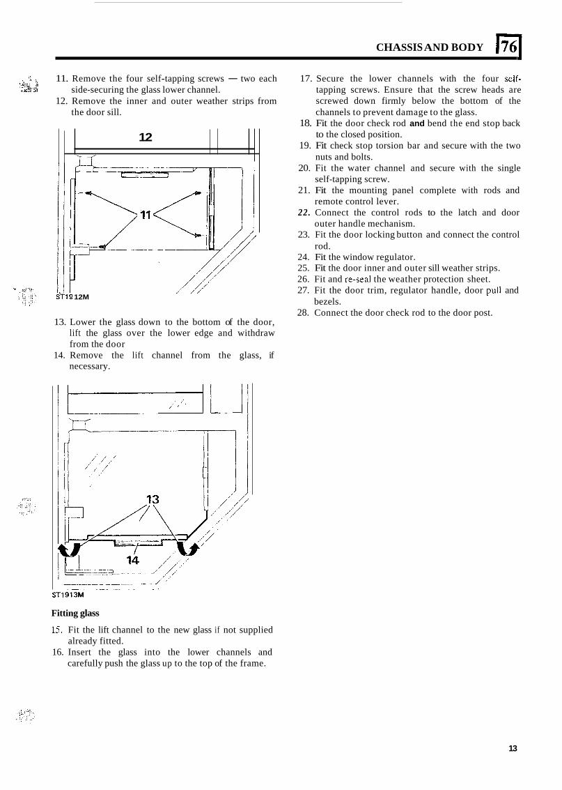
CHASSIS AND BODY (761
.: . . :...." .Y. ..L.-?
11. Remove the four self-tapping screws - two each
12. Remove the inner and outer weather strips from
'.*.<, a side-securing the glass lower channel.
the door sill.
12
'7 Y
/ / / 12M
/
13. Lower the glass down to the bottom of the door, lift the glass over the lower edge and withdraw from the door
14. Remove the lift channel from the glass, if necessary.
- / ' . , . .. . . ..-. ~
ST1913M
Fitting glass
15. Fit the lift channel to the new glass if not supplied
16. Insert the glass into the lower channels and already fitted.
carefully push the glass up to the top of the frame.
17. Secure the lower channels with the four self- tapping screws. Ensure that the screw heads are screwed down firmly below the bottom of the channels to prevent damage to the glass.
18. Fit the door check rod and bend the end stop back to the closed position.
19. Fit check stop torsion bar and secure with the two nuts and bolts.
20. Fit the water channel and secure with the single self-tapping screw.
21. Fit the mounting panel complete with rods and remote control lever.
22. Connect the control rods to the latch and door outer handle mechanism.
23. Fit the door locking button and connect the control rod.
24. Fit the window regulator. 25. Fit the door inner and outer sill weather strips. 26. Fit and re-seal the weather protection sheet. 27. Fit the door trim, regulator handle, door pull and
28. Connect the door check rod to the door post. bezels.
13
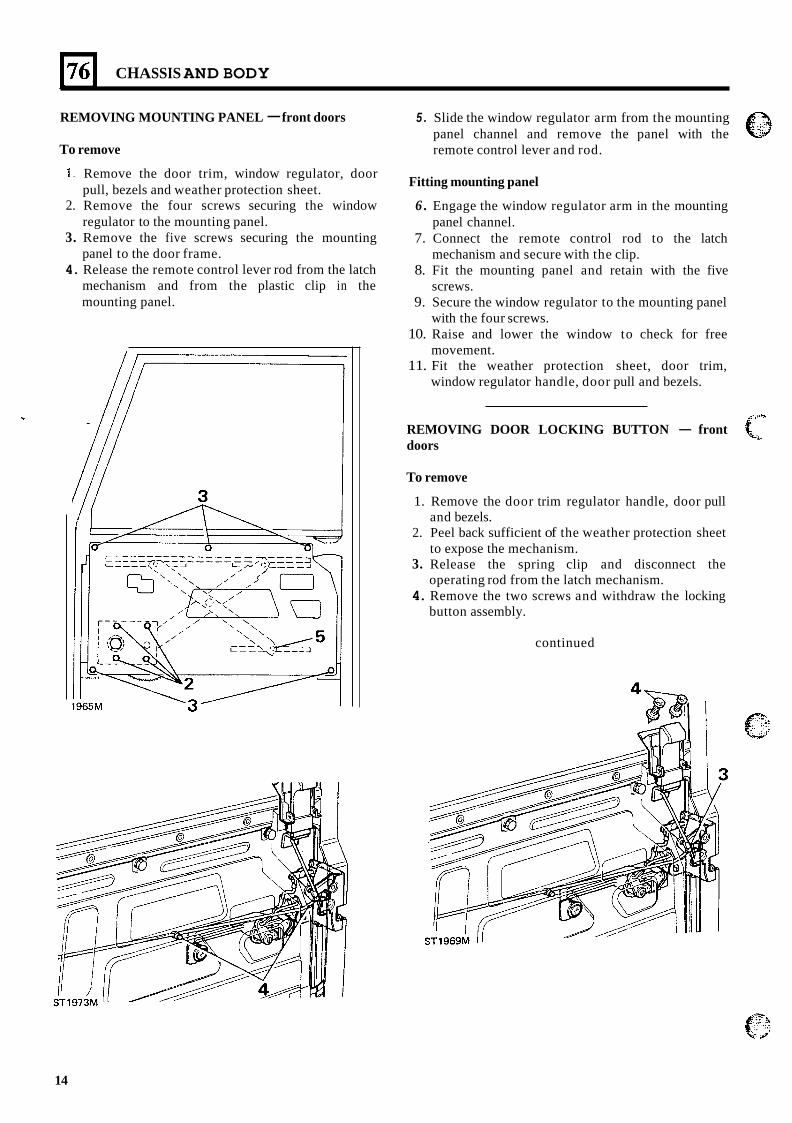
1761 CHASSIS AND BODY
REMOVING MOUNTING PANEL - front doors
To remove
1. Remove the door trim, window regulator, door pull, bezels and weather protection sheet.
2. Remove the four screws securing the window regulator to the mounting panel.
3. Remove the five screws securing the mounting panel to the door frame.
4. Release the remote control lever rod from the latch mechanism and from the plastic clip in the mounting panel.
5 . Slide the window regulator arm from the mounting panel channel and remove the panel with the remote control lever and rod.
Fitting mounting panel
6 . Engage the window regulator arm in the mounting panel channel.
7. Connect the remote control rod to the latch mechanism and secure with the clip.
8. Fit the mounting panel and retain with the five screws.
9. Secure the window regulator to the mounting panel with the four screws.
10. Raise and lower the window to check for free movement.
11. Fit the weather protection sheet, door trim, window regulator handle, door pull and bezels.
REMOVING DOOR LOCKING BUTTON - front doors
To remove
1. Remove the door trim regulator handle, door pull
2. Peel back sufficient of the weather protection sheet
3. Release the spring clip and disconnect the
4. Remove the two screws and withdraw the locking
and bezels.
to expose the mechanism.
operating rod from the latch mechanism.
button assembly.
continued
14
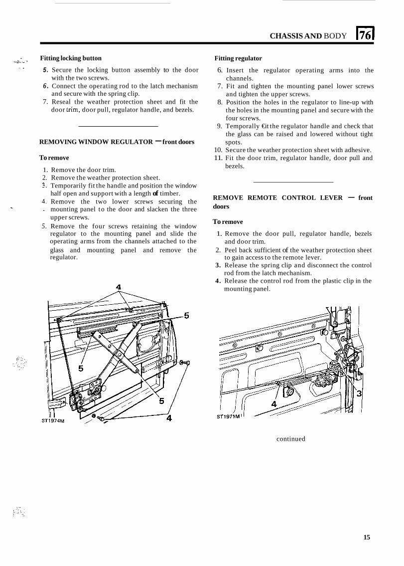
CHASSIS AND BODY El i.2: I -.. ‘I .. ” Fitting locking button Fitting regulator
5. Secure the locking button assembly to the door with the two screws.
6 . Connect the operating rod to the latch mechanism and secure with the spring clip.
7. Reseal the weather protection sheet and fit the door tnm, door pull, regulator handle, and bezels.
.. .
REMOVING WINDOW REGULATOR - front doors
To remove
6. Insert the regulator operating arms into the channels.
7. Fit and tighten the mounting panel lower screws and tighten the upper screws.
8. Position the holes in the regulator to line-up with the holes in the mounting panel and secure with the four screws.
9. Temporally €it the regulator handle and check that the glass can be raised and lowered without tight spots.
10. Secure the weather protection sheet with adhesive. 11. Fit the door trim, regulator handle, door pull and
bezels. 1. Remove the door trim. 2. Remove the weather protection sheet. 3. Temporarily fit the handle and position the window
half open and support with a length of timber. 4. Remove the two lower screws securing the
T doors ~ mounting panel to the door and slacken the three
upper screws. 5. Remove the four screws retaining the window
regulator to the mounting panel and slide the 1. Remove the door pull, regulator handle, bezels operating arms from the channels attached to the glass and mounting panel and remove the 2. Peel back sufficient of the weather protection sheet regulator.
3. Release the spring clip and disconnect the control
4. Release the control rod from the plastic clip in the
REMOVE REMOTE CONTROL LEVER - front
To remove
and door trim.
to gain access to the remote lever.
rod from the latch mechanism.
4 mounting panel.
continued
15
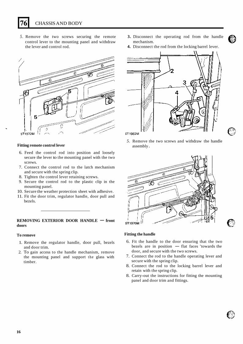
76’
5. Remove the two screws securing the remote 3. Disconnect the operating rod from the handle control lever to the mounting panel and withdraw the lever and control rod.
mechanism. 4. Disconnect the rod from the locking barrel lever.
CHASSIS AND BODY
Fitting remote control lever
6. Feed the control rod into position and loosely secure the lever to the mounting panel with the two screws.
7. Connect the control rod to the latch mechanism and secure with the spring clip.
8. Tighten the control lever retaining screws. 9. Secure the control rod to the plastic clip in the
10. Secure the weather protection sheet with adhesive. 11. Fit the door trim, regulator handle, door pull and
mounting panel.
bezels.
REMOVING EXTERIOR DOOR HANDLE - front doors
To remove
1. Remove the regulator handle, door pull, bezels and door trim.
2. To gain access to the handle mechanism, remove the mounting panel and support t he glass with timber.
sTi 9 8 2 ~
5. Remove the two screws and withdraw the handle assembly .
Fitting the handle
6. Fit the handle to the door ensuring that the two bezels are in position - flat faces ’towards the door, and secure with the two screws.
7. Connect the rod to the handle operating lever and secure with the spring clip.
8. Connect the rod to the locking barrel lever and retain with the spring clip.
8. Carry-out the instructions for fitting the mounting panel and door trim and fittings.
16
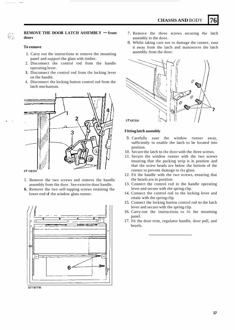
CHASSIS AND BODY
REMOVE THE DOOR LATCH ASSEMBLY - front doors
76
To remove
1. Carry out the instructions tc remove the mounting
2. Disconnect the control rod from the handle
3. Disconnect the control rod from the locking lever
4. Disconnect the locking button control rod from the
panel and support the glass with timber.
operating lever.
on the handle.
latch mechanism.
ST1983M
5 . Remove the two screws and remove the handle assembly from the door. See exterior door handle.
6. Remove the two self-tapping screws retaining the lower end of the window glass runner.
ST 1 977 M
7. Remove the three screws securing the latch assembly to the door.
8. Whilst taking care not to damage the runner, ease it away from the latch and manoeuvre the latch assembly from the door:
Fitting latch assembly
9. Carefully ease the window runner away, sufficiently to enable the latch to be located into position.
10. Secure the latch to the door with the three screws. 11. Secure the window runner with the two screws
ensuring that the packing strip is in position and that the screw heads are below the bottom of the runner to prevent damage to t h e glass.
12. Fit the handle with the two screws, ensuring that the bezels are in position.
13. Connect the control rod to the handle operating lever and secure with the spring clip.
14. Connect the control rod to the locking lever and retain with the spring clip.
15. Connect the locking button control rod to the latch lever and secure with the spring clip.
16. Carry-out the instructions to fit the mounting panel.
17. Fit the door trim, regulator handle, door pull, and bezels.
17
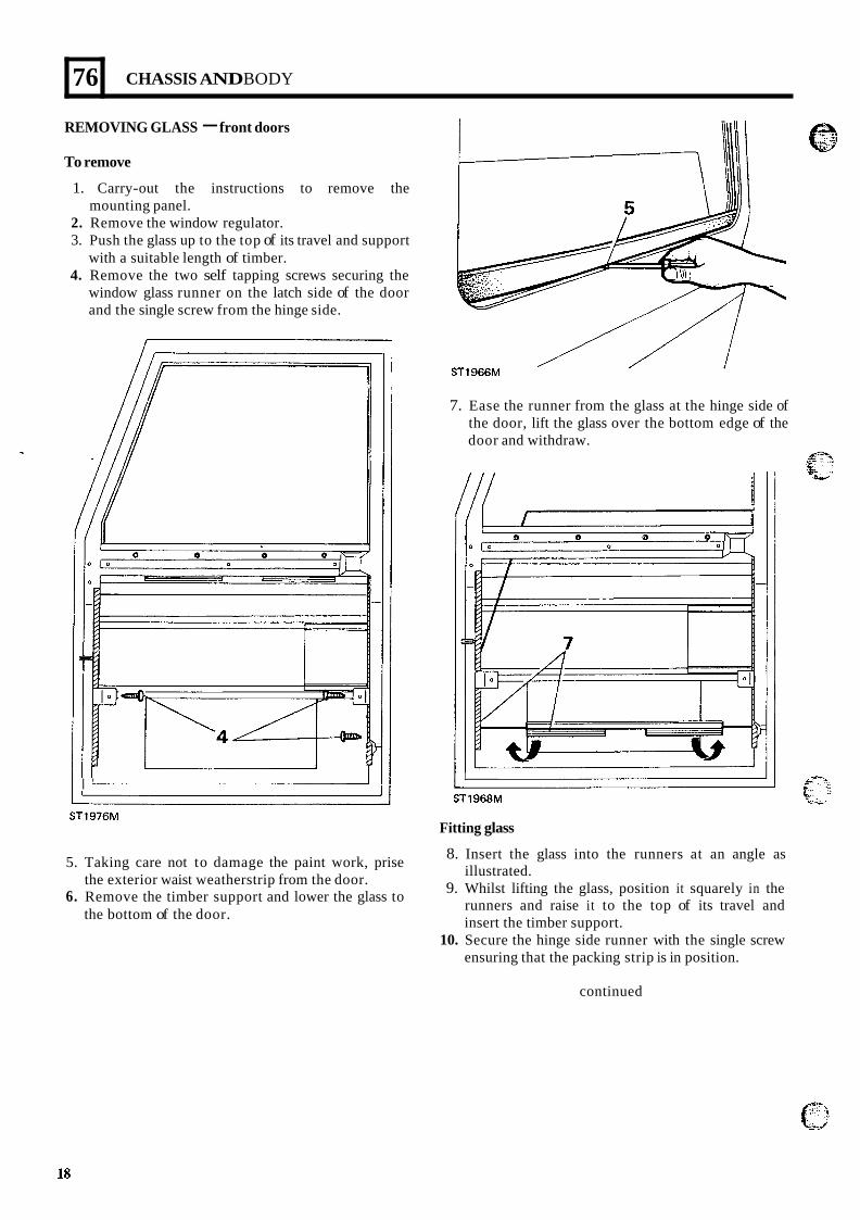
76
REMOVING GLASS - front doors
CHASSIS AND BODY
To remove
1. Carry-out the instructions to remove the
2. Remove the window regulator. 3. Push the glass up to the top of its travel and support
with a suitable length of timber. 4. Remove the two self tapping screws securing the
window glass runner on the latch side of the door and the single screw from the hinge side.
mounting panel.
I ' 1
ST1976M
5. Taking care not to damage the paint work, prise
6. Remove the timber support and lower the glass to the exterior waist weatherstrip from the door.
the bottom of the door.
7. Ease the runner from the glass at the hinge side of the door, lift the glass over the bottom edge of the door and withdraw.
I
ST1968M
Fitting glass
8. Insert the glass into the runners at an angle as illustrated.
9. Whilst lifting the glass, position it squarely in the runners and raise it to the top of its travel and insert the timber support.
10. Secure the hinge side runner with the single screw ensuring that the packing strip is in position.
continued
18
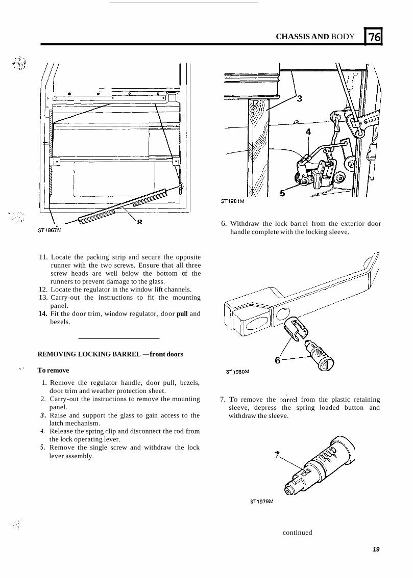
CHASSIS AND BODY
I e 0
76
ST1967M
11. Locate the packing strip and secure the opposite runner with the two screws. Ensure that all three screw heads are well below the bottom of the runners to prevent damage to the glass.
12. Locate the regulator in the window lift channels. 13. Carry-out the instructions to fit the mounting
14. Fit the door trim, window regulator, door pull and panel.
bezels.
REMOVING LOCKING BARREL -front doors
'' ' To remove
ST1981M
6. Withdraw the lock barrel from the exterior door handle complete with the locking sleeve.
ST1980M
1. Remove the regulator handle, door pull, bezels,
2. Carry-out the instructions to remove the mounting
3 . Raise and support the glass to gain access to the
4. Release the spring clip and disconnect the rod from
5. Remove the single screw and withdraw the lock
door trim and weather protection sheet.
panel.
latch mechanism.
the lock operating lever.
7. To remove the bane1 from the plastic retaining sleeve, depress the spring loaded button and withdraw the sleeve.
lever assembly. 7
ST1979M
continued
19
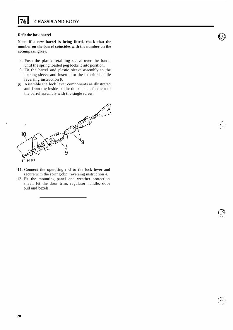
1761 CHASSIS AND BODY
Refit the lock barrel
Note: If a new barrel is being fitted, check that the number on the barrel coincides with the number on the accompaaing key.
8. Push the plastic retaining sleeve over the barrel until the spring loaded peg locks it into position.
9. Fit the barrel and plastic sleeve assembly to the locking sleeve and insert into the exterior handle reversing instruction 6 .
10. Assemble the lock lever components as illustrated and from the inside of the door panel, fit them to the barrel assembly with the single screw.
ST1978M
11. Connect the operating rod to the lock lever and secure with the spring clip, reversing instruction 4.
12. Fit the mounting panel and weather protection sheet. Fit the door trim, regulator handle, door pull and bezels.
20