2-channel, 2-model memory am computer racing system · 3 st rev•norm— channel st = steering th...
TRANSCRIPT

2-Channel, 2-Model MemoryAM Computer Racing System
5189 JR XR-2i manual 9/18/02 12:01 PM Page 1

2
Key Input and Display 11Display Screens 12
Normal Display 12Low Battery 12Lithium Battery 12Memory Backup 12
Accessing the System Mode 13Model Select 14Model Name Entry 14Grip Button C Funtion Select 15Data Reset 16
Accessing the Function Mode 17End-Point Adjustment 18Sub-Trim 19Servo Reversing 20Accessing the Direct Trim Mode 21Steering Trim 22Throttle Trim 23Grip Lever B: Steering Dual- Rate Trim Adjustment STG 24Grip Lever A: Brake End-PointAdjustment BRK 25
XR2i Data Sheets 26Frequency Chart 27Warranty and 27/28Service Information
Introduction to XR2i Quick Start Setup 3Direct Trim Access 4
Steering and Throttle/Trim Adjustment 4
System Features 5Transmitter 5Receiver 5Servos 5
System Specifications 6Components 6Transmitter 6Receiver 6Servos 6
Control Identification and Location 7RC Safety Precautions 8Steering Tension Adjustment 9Charging Jack 9Receiver/Servo Connections and Installation 10Operating Your Model 11Servo Layout 11
Table of Contents
Thank you for purchasing the XR2i 2-channel radiosystem. This system has been designed to provide RCracers with a high-quality, user-friendly radio systemthat can be relied upon year after year, race after race.It is important that you carefully read this manualbefore attempting to operate your XR2i system.
For your convenience, a blank data sheet has beenincluded in the back of this manual. Once you haveinput all the necessary data for a particular model into
your transmitter, we strongly recommend that youimmediately write down that information on the datasheet provided. This will insure that in the rare case ofa memory failure, you will not lose the models setup data.
For those who would like to get out to the track quickly with just the basic radio setup, please refer to the Quick Start section that follows.
Introduction
5189 JR XR-2i manual 9/18/02 12:01 PM Page 2

3
st
—R E V • N O R M
ChannelST = SteeringTH = Throttle
Servo Direction
st
100
E P A
Adjustment positionST = SteeringTH = Throttle
Current Value
XR2i Quick Start SetupIncluded in this manual are in-depth instructionsdetailing all the steps and procedures needed to correctly program each of the XR2i's features. QuickStart covers the basic programming information
necessary to get you to the track fast. Later, when youwant to learn more about the specific features of theXR2i, refer to the appropriate page(s) in this manualfor more detailed programming information.
Servo Reversing End-Point (Travel) Adjustment
1. With the transmitter power switch on, press the Scroll key to enter the Function mode.
SCROLLENTER
CHANNEL
CHANNEL
SCROLL
INCREASECLEAR
DECREASE
INCREASECLEAR
DECREASE
INCREASECLEAR
DECREASE
CHANNEL
2. Press the Scroll key until "REV.NORM" appears on the screen. The "ST" indicates the steering servo reversing screen.
3. Press the Increase or Decrease key to move the cursor to the desired servo direction (Rev.Norm).
4. Press the Channel key once to access the throttle servo reversing screen.
5. To select the direction of the throttle servo, repeat Step 3 above.
1. From the Servo Reverse function, press the Scrollkey once to access the End-Point (Travel) Adjustmentfunction (the EPA screen with "ST" will appear).
Steering Adjustment2. Rotate the steering wheel in the desired direction
(left or right) to be adjusted.
3. Press the Increase or Decrease keys to select the desired travel value.
Throttle Adjustment
4. Press the Channel key once. "TH" will appear on the screen.
5. Pull the trigger for foward or push the trigger for brake adjustment.
6. Press the Increase or Decrease keys to select the desired travel value.
5189 JR XR-2i manual 9/18/02 12:01 PM Page 3

4
Direct Trim AccessSteering and Throttle TrimAdjustment
Steering 1. With the transmitter power switch on, move the digital
steering trim lever in the desired position to be adjusted.The steering trim value screen will appear automatically.
Throttle2. With the transmitter power switch on, move the digital
throttle trim lever in the desired position to be adjusted.The throttle trim value screen will appear automatically.
stc
0
T R I M
thc
0
T R I M
Steering TrimFunction
Throttle TrimFunction
Current Value
brk
50
E P ABrake Function
Current Value
Current Value
R/B
ST.
Throttle Trim
Steering Trim
5189 JR XR-2i manual 9/18/02 12:01 PM Page 4

5
Transmitter• 2 channels• AM modulation• Easy-to-read LCD graphics display• 2-model memory• 3-character model name entry• Electronic digital trim levers for throttle and steering• Assignable electronic grip lever• Direct display trim function• Servo reversing• Sub-trim• Steering dual-rate• Steering end-point adjustment
(two points: left and right)• Brake/throttle end-point adjustment• Low-battery alarm• Plug-in crystals• Charge jack receptacle (rechargeable batteries not
included; order JRPB958)
R-125 Receiver• 2 channels• AM modulation• 27MHz/75MHz available• Battery Eliminator Circuitry (BEC)• Patented ABC&W interference technology
Z590M Servo• Metal gears for durability• Great high torque car/buggy steering servo• Indirect drive feedback potentiometer for additional
vibration protection• Surface Mount Technology (SMT)
Z270 Servo• Low current drain• Indirect drive feedback potentiometer for additional
vibration protection• Surface Mount Technology (SMT)• Durable nylon gear train
System Features
5189 JR XR-2i manual 9/18/02 12:01 PM Page 5

6
Transmitter XR2iReceiver R-125Servos Z590M x 1
Z270 x 1Accessories BEC switch harness with
battery case, servo accessories(for each servo), instruction manual
R-125 Receiver
Z270 Servo
Components
Model number XR2iEncoder 2-channel computer systemRF output 27MHz/75MHzModulation AMOutput power 195mWCurrent Drain 150mAPower source 1.5V x 8 dry cell
(1.2V x 8 Ni-Cd optional)Output pulse 1000–2000 (1500 neutral)
XR2i Transmitter
Torque 49 ounce inch (@6.0V)Speed .19 sec/60° (@6.0V)Weight 1.5 ozSize (WxLxH) 0.73" x 1.51" x 1.37"Motor 3-pole ferrite
Torque 85 ounce inch (@6.0V)Speed .15 sec/60° (@6.0V)Weight 1.6 ozSize (WxLxH) 0.73" x 1.55" x .146"Motor 3-pole ferrite
Model number NER-125Type 2-channel/AM
ABC&W circuitryFrequency 27MHz/75MHzSensitivity 5qs minimum(microseconds)Selectivity 8 KHz/50dBWeight 1 ozSize (WxLxH) 1.25" x 1.75" x 0.81"Receiver Antenna 20"Power supply 4.8–6.0V DC
Z590M Servo
System Specifications
5189 JR XR-2i manual 9/18/02 12:01 PM Page 6

7
Antenna
Electronic Digital SteeringTrim Lever
Electronic Digital Throttle Lever
Multi DataLCD Display
Three-Character Name Input
Digital VoltageReading
Electronic Digital Grip Lever A
Electronic DigitalGrip Lever B
Power Switch
Charge Jack
Scroll Button= Enter Function
= Clear Function
Channel Button
Decrease Button
Increase Button
Steering Tension (Adjustable)
Steering Wheelwith Foam Grip
Throttle Trigger(Adjustable)Grip Button C
Battery Cover *(8 “AA
„Batteries Required)
*To remove the battery cover, press down on the arrow and push the cover in thedirection of the arrow. Remove the battery case and install 8 "AA" batteries in thedirection shown as molded into the battery case. If the transmitter voltage fails to register, check for correct battery installation and voltage.
Control Identification and Location
5189 JR XR-2i manual 9/18/02 12:01 PM Page 7

8
RC Safety Precautions
Transmitter Crystal Replacement Notice
For safe and reliable performance of your RC model,please carefully read and follow the guidelines below.
1. Radio control models are not toys. They are capable of inflicting serious injury to people and property. Use caution at all times when operating your model.
2. You are responsible for the safe operation of your RC model. You must properly install, test and operate your model with a clear sense of that responsibility. Do not take risks that might endanger yourself or others.
3. Running an RC car in the streets is very dangerousto both drivers and models. Avoid running your model in areas occupied by full-size automobiles. To locate areas where you can safely operate your model, contact your local hobby shop for RC tracksor clubs in your area.
4. When running an RC boat, keep it away from any swimmers, full-size boats and wildlife. Also, watch carefully for fishing lines that may get tangled in the propeller.
5. Before operating your model, make sure your frequency is clear. If someone else is operating on the same frequency, both models will go out of control, possibly causing damage to the models, aswell as others.
6. If at any time while operating your RC model you sense abnormal model functioning, end your operation immediately. Do not operate your model again until you are certain the problem has been corrected.
Caution: Control of your model is impossiblewithout sufficient voltage for the transmitter andreceiver. A weak transmitter battery will decreaseyour range of operation, and a weak receiver bat-tery will slow servo movement and decreaseyour range of operation. Check your receiverpack voltage often to avoid losing control of yourmodel. When using a model that operates boththe electric motor and the receiver from thesame battery (Battery Eliminating Circuitry orBEC), you should discontinue use when the topspeed sharply decreases or you'll quickly losecontrol of your model.
The Federal Communications Commission (FCC)requires that changes in transmitter frequencymust be performed only by an authorized servicetechnician (Horizon Service Center). Any transmitterfrequency changes made by a non-certified technician may result in a violation of FCC rules.
Crystal
5189 JR XR-2i manual 9/18/02 12:01 PM Page 8

9
Steering Tension Adjustment
Charging Jack
Steering tension is adjustable via the recessed screwlocated beneath the steering wheel (see page 7 for
exact location). Turning the screw clockwise increas-es the steering tension.
Charger Pigtail For Transmitter
Black To Positive
Red To Negative
JR TRANSMITTER CHARGE JACK POLARITY:
Located on the left-hand side of the transmitter is thecharging jack that accepts only JR wall chargers.Please do not attempt to use any other brand of wallcharger, as it may be reverse polarity and can cause
damage to your system. Only use the JR wall chargerwhen the XR2i is equipped with Ni-Cd batteries(JRPB958, available separately).
5189 JR XR-2i manual 9/18/02 12:01 PM Page 9

10
Receiver/Servo Connections and Installation
Your R-125 receiver is equipped with BatteryEliminator Circuitry (BEC). The receiver gets its power from the model’s Ni-Cd battery pack, thus saving the weight of an additional receiver battery.Ni-Cd batteries from 4.8–8.4V (4–7 cells) can beused safely. Higher voltage packs may damage thereceiver and servos.
Note: When using a separate receiver Ni-Cd as apower source, the operating voltage range is4.8–6.0V (4- to 5-cell).
Attention: Make sure the male and female connectorshave the correct polarity (+/-) before connecting. Theservo lead and receiver case are molded so that thelead can only be inserted correctly. Be sure to orientthe servo plug correctly for proper insertion.
You may use a separate receiver battery to power the receiver (such as for some electric boats or in gas-powered vehicles). A Ni-Cd pack plugged into the battery socket on your receiver will operate yourreceiver. You can also use alkaline batteries with theincluded battery box.
If you use a mechanical speed controller, please make sure it has the correct connector for a BEC system (red connector). See Figure A below for a typical setup. Most electronic speed controllers areset up for BEC operation and plug directly into yourreceiver (Figure B). See Figure B for a typical setupand check your speed controller‘s manual forcorrect installation.
BEC
BEC
Figure A – Connections to BEC receiver with mechanical speed controller. Ni-Cd battery and speed controllerare not included in the radio set.
Figure B – Connections to BEC receiver with electronic speed controller. Ni-Cd battery and speed controllerare not included in the radio set.
To ResistorsMechanicalSpeed Control
BEC ConnectorSwitch
R-125 Receiver
R-125 Z270/Z590M Servos
To Motor
Battery Box(for use with optional separatereceiver battery power)
7.2V–8.4V Battery
7.2–8.4V Battery
R-125 Receiver
Third Channel(Optional)
R-125
Z270/Z590M Servo
ESC
To Motor
Third channel(Optional)
5189 JR XR-2i manual 9/18/02 12:01 PM Page 10

11
Operating Your Model
Servo Layout
It’s important to learn the proper sequence for switching on/off your radio system.
Before OperationSwitch on the transmitter, then the receiver.
After OperationSwitch off the receiver, then the transmitter. Thisensures that you will always have a signal to the receiver and that your RC model will not operate out of control when you turn off the transmitter.
Servo Mounting Flange
Rubber Grommets
Rubber Grommets
Servo Case
Servo Lead with Connector
Servo Output Shaft
Servo Mounting FlangeServo Arm/Horn
Servo Arm Retaining Screw
Servo Eyelet
Z270/Z590M Servo
Top View
To enter the Function mode, press the Scroll keywhile the transmitter is on.
Press the Increase and Decrease keyssimultaneously to clear the screen or return
to factory preset.
To enter the System mode, press the Scrolland Channel keys simultaneously and hold
while turning on the transmitter.
KEY
SCROLL
CHANNEL
INCREASE
DECREASE
Moves up through the available functions
Selects the desired channel
Increases the value of the selected function
Decreases the value of the selected function
USE
SCROLLENTER
CHANNEL INCREASECLEAR
DECREASE
Key Input and Display
Note: Rubber grommetsand (sometimes) eyeletsare used in fuel-poweredvehicles.
5189 JR XR-2i manual 9/18/02 12:01 PM Page 11

12
Display Screens
Normal DisplayWhen the power switch is turned on, the LCD screenwill read as shown below. This screen is referred to asthe Normal Display.
Note: If any of the electronic trim buttons aremoved while in this screen, the screen will automatically change to display the trim in use.This is called the Direct Trim mode. For moreinformation on the feature, please see page 21of this manual.
Low Battery/Lithium Battery BackupWhen the voltage of the 8 "AA" batteries drops below9.0V, the XR2i's display screen will alternate betweenthe Normal and Low-Battery screen (BAT) and a con-tinuous beeping will occur, indicating that the batteries need to be replaced before further use. The Low-Battery screen is active during any operating modes.
Lithium BatteryYour XR2i radio system is equipped with a five-yearlithium battery backup system. This system isdesigned to protect and retain all radio programmingin the event that the transmitter batteries drop belowthe required 9.0 volts, or the transmitter battery caseis removed during battery changes. If after five yearsit becomes necessary to replace the lithium battery,return your system to the Horizon Service Center forrepair (see address, page 28).
Memory BackupIf the Memory Backup screen appears, this indicatesthe possibility of a ROM problem or the lithiumbattery is dead. If you switch the power off and onagain, but the transmitter is in the default mode withall data lost, it is strongly suggested that the XR2itransmitter be returned to the Horizon Service Centerfor servicing (see Warranty Information page 27).
bat
8.9V
bak
ER
md !
10.2V
5189 JR XR-2i manual 9/18/02 12:01 PM Page 12

13
Accessing the System Mode
To enter the System mode, press both the Scroll andChannel keys at the same time while turning on thetransmitter power switch. By pressing the Scroll key,you can now choose Model Select, Model Name Input,Grip button C function or the Data Reset function asshown here on the System Mode flow chart.Information for each function is located on the page number listed next to the function name on the flow chart.
To exit the System mode, press the Scroll and Channel keys at the same time or simply turn off the transmitter.
Note: If you turn the transmitter off and immedi-ately enter System mode again, you will bereturned to the last System mode function usedinstead of the model select function. While inSystem mode, there is no RF output generated bythe transmitter. Adjustments can be performedwith reduced battery power consumption. If youexit System mode by pressing the Scroll andChannel key at the same time, RF output will notbe enabled until you first turn off the transmitter.
Model Name Entry(page 14)
21md !
1
mdl
1
Model Select (page 14)
20
clr
1
gbc
0
Data Reset (page 16)
25
Grip Button CFunction(page 15)
5189 JR XR-2i manual 9/18/02 12:01 PM Page 13

14
Model Name Entry(System Mode)
Model Select(System Mode)
The XR2i has memory for two models. This featureallows for two different models to be operated withthe same transmitter (additional receivers and servosmust be purchased separately) or one model withtwo different race setups.
Accessing the Model Select Function
1. Press the Scroll and Channel keys at the same timeand hold.
2. Turn the transmitter power switch on to enter System mode.
3. If "MDL" does not appear on the screen, press the Scroll key until "MDL" appears.
4. Press the Increase or Decrease keys to select the desired model number (1 or 2).
5. Press the Scroll key to access the Model Name Entry function.
6. To exit System mode, either turn the transmitter power switch off or press the Scroll and Channel keys at the same time.
md !
1
Character tobe Adjusted
Current ModelNumber
mdl
1
Model SelectFuction
Current ModelNumber
Press and hold theScroll and Channel keysat the same time whileturning transmitterpower switch on.
Press the Increaseor Decrease keys toselect the desiredmodel to be used(1 or 2).
Press and hold the Scrolland Channel keys at thesame time while turningtransmitter power switchon. Next, press the Scrollkey until the flashing “M” appears.
Press the Channelkey to select thecharacter to be
changed.
Press the Increase orDecrease keys to select the correctletter/number to be used.
SCROLLENTER
CHANNEL
INCREASECLEAR
DECREASE
SCROLLENTER
CHANNEL
INCREASECLEAR
DECREASE
The XR2i allows a three-character name to be inputfor each of the two models available. The currentmodel with name will then be displayed in the Normaldisplay screen. This feature is useful to help identifydifferent models, setups, etc.
Accessing the Model NameEntry Function
1. Press the Scroll and Channel keys at the same timeand hold.
2. Turn on the transmitter power switch to enter the System mode.
3. Press the Scroll key until "MD1" appears on the screen with the first character flashing.
4. Press the Increase or Decrease keys to select the correct letter/number for the first character (flashing).
5. To change the remaining two characters, press the Channel key until the desired character to be changed is flashing.
6. Press the Scroll key to access the Grip Button C function.
7. To exit the System mode, either turn the transmitter power switch off or press the Scrolland Channel keys at the same time.
5189 JR XR-2i manual 9/18/02 12:01 PM Page 14

15
Grip Button C Function Select (System Mode)
The Grip Button C function of the XR2i allows you toselect from 2 different functions available. Use theinformation below to select the correct Grip Button Cassignment for your particular installation.
0 = The 0, or off function, is the default setting anddoes not assign a function to Grip Button C.
Eb = The Eb or Emergency Steering Button function isdesigned to override the value of Grip Dial B and pro-vide 100% steering rate. This feature is useful if youhave reduced the steering rate to make your vehicleeasier to drive but need full steering in an emergencysituation such as a collision.
Accessing the Grip Button C Function1. Press the Scroll and Channel keys at the same time
and hold.2. Turn on the transmitter power switch to enter
System mode.3. Press the Scroll key until "GBC" appears on
the screen.4. Press the Increase or Decrease key to select the
correct Grip Button C function type to be used.5. Press the Scroll key to access the Data Reset
function.6. To exit the System mode, either turn the
transmitter power switch off or press the Scroll andChannel keys at the same time.
gbc
0
Grip Button CFunction
Grip Button C is Inhibited
gbc
EB
Grip Button CFunction
Emergency Steering Button is Activated
5189 JR XR-2i manual 9/18/02 12:01 PM Page 15

16
Data Reset (System Mode)
The Data Reset function allows you to reset all theprogramming in the selected model (1 or 2) to thefactory default settings. Before using the Data Resetfunction, it is important to enter the Model Selectfunction and check to make sure the current modelnumber indicated (1 or 2) is the model to which youwant to reset to the factory default settings. TheModel Select function is described on page 14.
Accessing the Data Reset Function
1. Press the Scroll and Channel keys at the same time and hold.
2. Turn on the transmitter power switch to enter the System mode.
3. Press the Scroll key until "CLR" appears on the screen.
4. Press the Increase and Decrease keys at the same time to reset the data. To confirm that the selected model's programming has been reset, a beep will sound and the model number selected (1 or 2) will stop flashing.
5. Press the Scroll key to access the Copy Model Data function.
6. To exit the System mode, either turn the transmitter power switch off or press the Scroll and Channel keys at the same time.
clr
1Model to be Reset
Press and hold the Scrolland Channel keys at thesame time while turningthe transmitter powerswitch on. Next, pressthe Scroll key until“CLR” appears.
Press the Increase and Decrease keys at thesame time to reset (clear) all settings for theselected model to the factory default settings
SCROLLENTER
CHANNEL
INCREASECLEAR
DECREASE
5189 JR XR-2i manual 9/18/02 12:01 PM Page 16

17
Accessing the Function Mode
To enter the Function mode, it is necessary to firstturn on the transmitter's power switch. Next, pressthe Scroll key until a beep is heard. The display willchange to show the first function listed on theFunction Mode flow chart as shown below. Press theScroll key to scroll down through the functions one byone, as shown in the flow chart. Once the desiredfunction has been reached, use the Channel key to
select the appropriate channel (if applicable). Toadjust the values of the function, simply press theIncrease (+) or Decrease (-) keys until the desiredvalue is displayed on the screen. To exit functionmode, press the Scroll and Channel keys at the sametime. The next time you enter Function mode, you willbe returned to the last function accessed.
sts
0
T R I M
st
100
E P A
ths
0
T R I M
st S B - T R M
Channel Key
Channel Key
Channel Key
Sub-Trim(page 19)
Servo Reversing(page 20)
—R E V • N O R M
—R E V • N O R M
R/BL/F
th
100
E P A
Channel Key
5189 JR XR-2i manual 9/18/02 12:01 PM Page 17

18
End-Point Adjustment (Function Mode)The End-Point Adjustment feature of the XR2i allowsthe maximum travel of both the steering and throttleservos to be increased or decreased in each directionto achieve the exact servo movement needed. TheEnd-Point Adjustment range is from 0% to 125% andis factory set to 100% for both channels. The valuedisplayed on the screen depends on the current position of the steering wheel, trigger, or trim lever tobe adjusted. This feature is very useful either to maximize servo travel or to reduce servo over-travel
to eliminate servo binding (servo moves further thancontrol mechanism allows), without the need formechanical linkage adjustment.
The screens below are accessed by turning the wheelto the desired direction to be adjusted (left or right),by moving the trigger to the forward or backward(brake) position, or by moving the Grip Lever A to theforward or back positions.
L/F
st
100
E P A
R/B
st
100
E P A
Steering Left End-Point Adjustment
Current ValueValues: 0 to 125Clear = 100
Steering Right End-Point Adjustment
Current ValueValues: 0 to 125Clear = 100
L/F
th
100
E P A
R/B
th
100
E P A
Forward Throttle End-Point Adjustment
Current ValueValues: 0 to 125Clear = 100
Backward Throttle (Brake)End-Point Adjustment
Current ValueValues: 0 to 125Clear = 100
5189 JR XR-2i manual 9/18/02 12:01 PM Page 18

19
Accessing The End-PointAdjustment Function
1. Turn on the transmitter power switch.2. Press the Scroll key to enter Function mode.3. Press the Scroll key until "EPA" appears in small
letters on the left side of the screen.
4. Press the Channel key to select the desired channel to be adjusted.Steering = ST R/B(steering right) or ST L/F (steering left)Throttle = TH L/F (forward) or TH R/B (braking or reverse)
5. Move the steering wheel or trigger in the desired direction for adjustment (left/right, forward/reverse or brake). Press the Increase or Decrease key to achieve the desired amount of travel. Move the wheel or trigger in the opposite direction to adjust the travel in the opposite direction.
6. Press the Scroll key to access the Sub-Trim function.
7. To exit the Function mode, either turn off the transmitter power switch or press the Scroll and Channel keys at the same time.
Note: When setting the end point adjustment values for the steering function, it is suggestedthat, if possible, the maximum travel values be set to an equal value in both directions to maintain proper steering control.
Sub-Trim (Function Mode)
Press the Scroll keyuntil "EPA" appears onthe screen
Press the Channel keyto select the channel tobe adjusted
Move the wheel/trigger or Grip Button C in the desired direction and presseither the Increase or Decrease keys to achieve the desired travel value
SCROLLENTER
CHANNEL
INCREASECLEAR
DECREASE
The Sub-Trim function of the XR2i is an electronictrimming feature that allows the neutral position ofthe servo on either the steering or throttle channel tobe moved, while allowing the electronic trim lever forthat channel to remain in the center position. This fea-ture is very useful, as it allows the servo arm/wheelposition to be moved to help with control linkageinstallation, eliminating the need to make mechanicallinkage adjustments.
Although the Sub-Trim function is a very usefulfeature, it is suggested that only small amounts ofsub-trim be used so that no unwanted, non-equalservo travel is created. It is suggested that less than30 points of Sub-Trim be used during adjustment. Ifmore than 30 points of Sub-Trim are required, it issuggested that a mechanical linkage adjustment beperformed.
Accessing the Sub-Trim Function
1. Turn on the transmitter power switch.2. Press the Scroll key to enter Function mode.3. Press the Scroll key until "TRIM" appears in small
letters to the left of the screen.4. Press the Channel key to select the channel to be
adjusted (Steering, Throttle or Auxiliary Channel 3).5. Press the Increase or Decrease keys until the
proper servo position is achieved.6. Press the Scroll key to access the Servo
Reversing function.7. To exit the Function mode, either turn off the
transmitter power switch or press the Scroll and Channel keys at the same time.
sts
0
T R I M
Current ChannelSTS = SteeringTHS = ThrottleAUS = Auxiliary
Channel 3
Current Value
Press the Channel keyto select the desiredchannel to be adjusted.
STS = SteeringTHS = ThrottleAUS = Auxiliary
Channel 3
Press the Scroll keyuntil "TRIM" appearson the screen.
Press the Increase or Decrease keys to achievethe desired Sub-Trim Value.
Values: R/B 125 0 R/F 125
SCROLLENTER
CHANNEL
INCREASECLEAR
DECREASE
5189 JR XR-2i manual 9/18/02 12:01 PM Page 19

20
Servo Reversing (Function Mode)The Servo Reversing feature of the XR2i is a very con-venient feature when setting up a new model. Thepurpose of the servo reversing function is to changethe direction of the servo rotation in relation to thewheel/trigger movement. The Servo Reversing function is available for the steering and throttle of the XR2i.
Accessing the ServoReversing Function
1. Turn the transmitter power switch on.2. Press the Scroll key to access Function mode.3. Press the Scroll key until "REV.NORM" appears in
small letters to the right of the screen.4. Press the Channel key to select the channel to be
changed (ST = Steering, TH = Throttle).5. Press the Increase or Decrease keys to move the
cursor to the desired direction.6. To exit the Function mode, either turn off the
transmitter power switch or press the Scroll and Channel keys at the same time.
Current ChannelST = SteeringTH = ThrottleAUX = Auxiliary
Channel 3
Current ServoDirection
st
—R E V • N O R M
Press the Channel keyto select the desiredchannel to be adjusted.
STS = SteeringTHS = ThrottleAUX = Auxiliary
Channel 3
Press the Mode keyuntil “REV. NORM”appears on the screen.
Press the Increase or Decrease keys to movethe cursor to the desired servo direction.
SCROLLENTER
CHANNEL
INCREASECLEAR
DECREASE
5189 JR XR-2i manual 9/18/02 12:01 PM Page 20

21
Accessing the Direct Trim Mode
stc
0
thc
0
brk
50
E P A
stg
70∞
R A T E
Steering Trim(page 22)
Throttle Trim(page 23)
Steering Dual-Rate(Grip Lever B)(page 24)
Brake Travel Adjustment (Grip Lever A), (page 25)
T R I M
T R I M
R/B
The Direct Mode function of the XR2i is accessiblethrough the use of the electronic throttle or steeringtrim levers, as well as the two electronic grip levers(A&B) located on the upper portion of the grip handle.This function allows for quick trim adjustment ofthese controls.
To access the Direct Trim Mode function, turn on thetransmitter power switch. Next, move the desired trimlever to be adjusted. The appropriate screen for theselected trim lever will be displayed. To adjust, simplymove the trim lever in the desired direction until thecorrect amount of trim is achieved. Once the desiredtrim is achieved, the screen will return to the Normaldisplay screen after approximately two seconds fromthe last trim input. If the Increase or Decrease keysare pressed any time during the two seconds, the system will return to the previous screen in use.
5189 JR XR-2i manual 9/18/02 12:01 PM Page 21

22
Steering Trim (STC)
T R I M .
Values: L/F 60 0 R/B 60
stc
0 Current Value
Press the Increase and Decrease keys at the sametime to reset the throttle trim value to zero.
Throttle Trim Location
Thro
ttle T
rim
Decrease
Increase
INCREASECLEAR
DECREASE
ST.
The XR2i electronic Steering Trim lever, located justabove the steering wheel, allows the center position ofthe servo to be manipulated in either direction toachieve precise centering of the steering assembly.Steering travel end-point adjustment values (page 24)remain completely independent from the steeringtrim, unless the trim value exceeds the selected end-point values. (For example, if trim values are set at 30 and end-point values at 15, steering trim will over-ride/alter the end-point value.)
To adjust the steering trim servo position, move theelectronic Steering Trim lever either to the left or theright. As soon as the trim is moved, the "STC"Steering Trim screen will appear and will continue tobe displayed unless the trim lever is untouched for aperiod of two seconds. To reset the trim value to 0,press the Increase and Decrease keys at the sametime while the "STC" screen is displayed.
Each click will provide 0.3° of trim to the center of thesteering servo with a maximum of 12° allowed.
Note: Each click will not always result in achange of the value displayed.
5189 JR XR-2i manual 9/18/02 12:01 PM Page 22
23
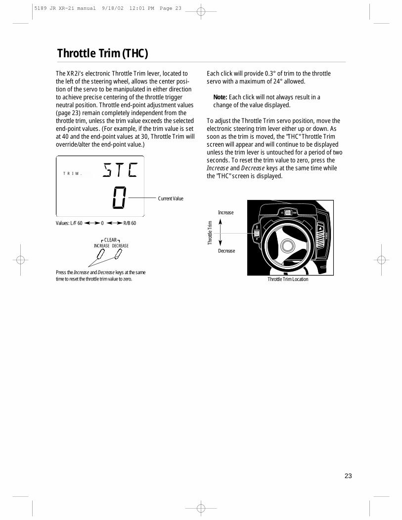
Throttle Trim (THC)The XR2i's electronic Throttle Trim lever, located tothe left of the steering wheel, allows the center posi-tion of the servo to be manipulated in either directionto achieve precise centering of the throttle triggerneutral position. Throttle end-point adjustment values(page 23) remain completely independent from thethrottle trim, unless the trim value exceeds the selectedend-point values. (For example, if the trim value is setat 40 and the end-point values at 30, Throttle Trim willoverride/alter the end-point value.)
Each click will provide 0.3° of trim to the throttleservo with a maximum of 24° allowed.
Note: Each click will not always result in achange of the value displayed.
To adjust the Throttle Trim servo position, move theelectronic steering trim lever either up or down. Assoon as the trim is moved, the "THC" Throttle Trimscreen will appear and will continue to be displayedunless the trim lever is untouched for a period of twoseconds. To reset the trim value to zero, press theIncrease and Decrease keys at the same time whilethe "THC" screen is displayed.
Throttle Trim Location
Thro
ttle T
rim
Decrease
IncreaseST.
T R I M .
Values: L/F 60 0 R/B 60
stc
0 Current Value
Press the Increase and Decrease keys at the sametime to reset the throttle trim value to zero.
INCREASECLEAR
DECREASE
5189 JR XR-2i manual 9/18/02 12:01 PM Page 23

24
Grip Lever B: Steering Dual-Rate Trim Adjustment (STG)
INCREASECLEAR
DECREASE
stg
70∞
R A T E
Current Value(20% to 100%)
Press the Increase and Decrease keys at the same time toreset the steering dual rate trim to the factory preset (70%).
Decrease Increase
Grip Lever BSteering Dual-Rate Trim
The Steering Dual-Rate adjustment, located at GripLever B, allows the Dual-Rate value (maximum servotravel) to be increased or decreased within a rangefrom 100% through 20% of the total end point valueestablished in the steering EPA function. This functionis very useful in race conditions as it allows you tocustom tailor the steering radius and sensitivity forthe current track conditions.
Please note that since the Dual-Rate value shown inthe "STG" screen is the percentage of the end-pointvalue established in the Steering EPA function, thevalue will not always increase or decrease each timeGrip Lever B is moved.
If the Emergency Steering button function (page 15)is active, pressing Grip Button C will restore the steer-ing dual rate to 100% until the button is released.
To adjust the Steering Dual-Rate value, move the elec-tronic Grip Lever B either left (-) or right (+). As soonas the trim is moved, the "STG" Steering Dual-Ratescreen will appear and will continue to be displayedunless the Grip Lever B is untouched for a period oftwo seconds. To reset the trim value to the factorypreset setting of 70%, press the Increase andDecrease keys at the same time while the "STG"screen is displayed.
5189 JR XR-2i manual 9/18/02 12:01 PM Page 24
25
Grip Lever A: Brake End-Point Adjustment BRK/AuxilaryChannel 3 Access
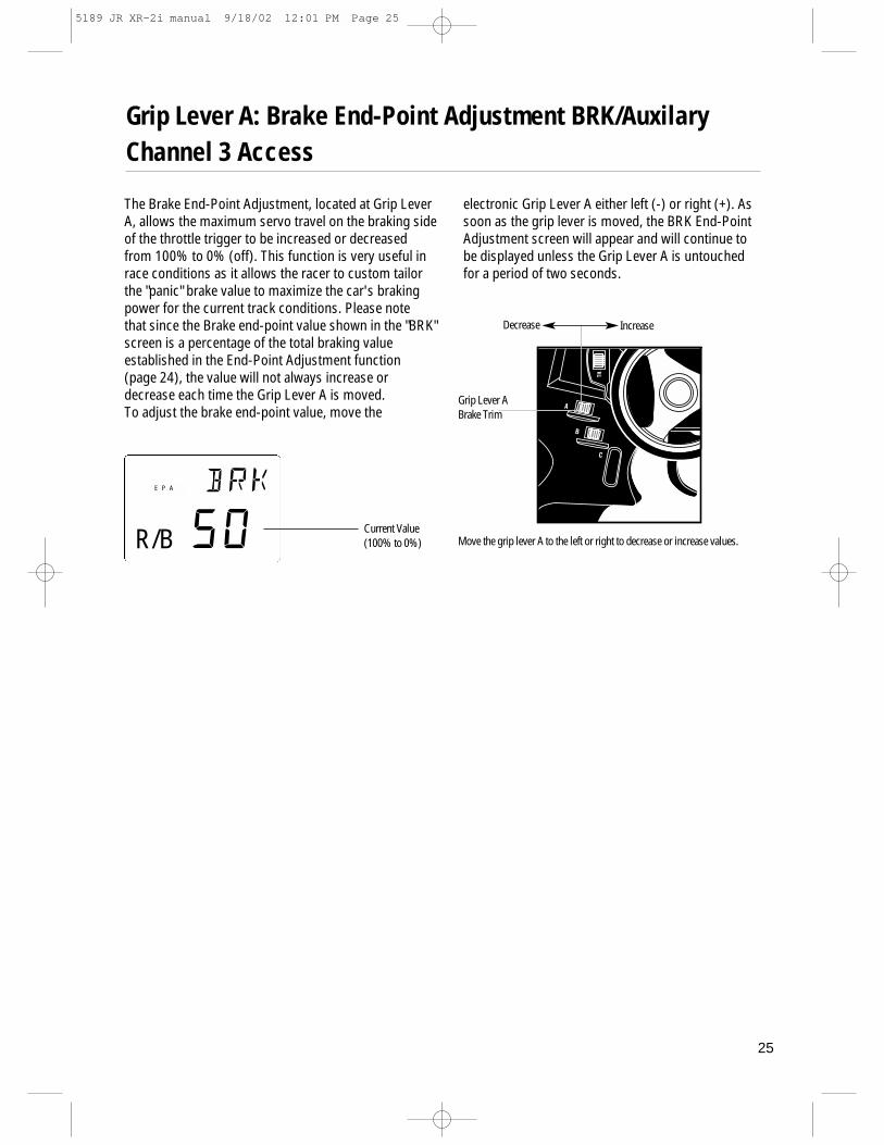
The Brake End-Point Adjustment, located at Grip LeverA, allows the maximum servo travel on the braking sideof the throttle trigger to be increased or decreasedfrom 100% to 0% (off). This function is very useful inrace conditions as it allows the racer to custom tailorthe "panic" brake value to maximize the car's brakingpower for the current track conditions. Please note that since the Brake end-point value shown in the "BRK"screen is a percentage of the total braking value established in the End-Point Adjustment function (page 24), the value will not always increase ordecrease each time the Grip Lever A is moved.To adjust the brake end-point value, move the
electronic Grip Lever A either left (-) or right (+). Assoon as the grip lever is moved, the BRK End-PointAdjustment screen will appear and will continue to be displayed unless the Grip Lever A is untouched for a period of two seconds.
Current Value(100% to 0%)
brk
50
E P A
Move the grip lever A to the left or right to decrease or increase values.R/B
Decrease Increase
Grip Lever ABrake Trim
5189 JR XR-2i manual 9/18/02 12:01 PM Page 25

26
STEERING THROTTLE
END-POINT ADJUSTMENT L__________ R__________ F__________ B__________
SUB-TRIM
SERVO REVERSING REV/NORM REV/NORM
Function Mode
MODEL NUMBER 1 2
MODEL NAME
GRIP BUTTON C O/E
System Mode
TRIM STEERING THROTTLE
VALUES –/+ –/+
GRIP LEVER BSTEERING D/R %
GRIP BRAKE EPA
LEVER A VALUES
Direct Mode
STEERING THROTTLE
SUB-TRIM
SERVO REVERSING REV/NORM REV/NORM
Function Mode
MODEL NUMBER 1 2
MODEL NAME
GRIP BUTTON C O/Eb
System Mode
TRIM STEERING THROTTLEVALUES –/+ –/+
GRIP LEVER BSTEERING D/R %
BRAKE EPA
GRIP LEVER A VALUES %
Direct Mode
XR2i Data Sheet
5189 JR XR-2i manual 9/18/02 12:01 PM Page 26
27
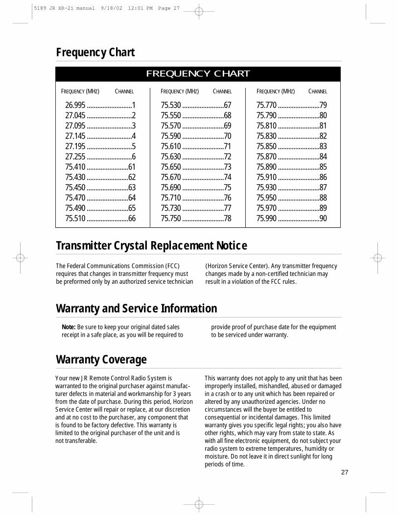
FREQUENCY (MHZ) CHANNEL FREQUENCY (MHZ) CHANNEL FREQUENCY (MHZ) CHANNEL
26.995 ..........................127.045 ..........................227.095 ..........................327.145 ..........................427.195 ..........................527.255 ..........................675.410 ........................6175.430 ........................6275.450 ........................6375.470 ........................6475.490 ........................6575.510 ........................66
75.530 ........................6775.550 ........................6875.570 ........................6975.590 ........................7075.610 ........................7175.630 ........................7275.650 ........................7375.670 ........................7475.690 ........................7575.710 ........................7675.730 ........................7775.750 ........................78
75.770 ........................7975.790 ........................8075.810 ........................8175.830 ........................8275.850 ........................8375.870 ........................8475.890 ........................8575.910 ........................8675.930 ........................8775.950 ........................8875.970 ........................8975.990 ........................90
FREQUENCY CHART
Frequency Chart
Transmitter Crystal Replacement Notice
The Federal Communications Commission (FCC)requires that changes in transmitter frequency mustbe preformed only by an authorized service technician
(Horizon Service Center). Any transmitter frequencychanges made by a non-certified technician mayresult in a violation of the FCC rules.
Warranty CoverageYour new JR Remote Control Radio System iswarranted to the original purchaser against manufac-turer defects in material and workmanship for 3 yearsfrom the date of purchase. During this period, HorizonService Center will repair or replace, at our discretionand at no cost to the purchaser, any component thatis found to be factory defective. This warranty is limited to the original purchaser of the unit and is not transferable.
This warranty does not apply to any unit that has beenimproperly installed, mishandled, abused or damagedin a crash or to any unit which has been repaired oraltered by any unauthorized agencies. Under nocircumstances will the buyer be entitled toconsequential or incidental damages. This limitedwarranty gives you specific legal rights; you also haveother rights, which may vary from state to state. Aswith all fine electronic equipment, do not subject yourradio system to extreme temperatures, humidity ormoisture. Do not leave it in direct sunlight for longperiods of time.
Warranty and Service InformationNote: Be sure to keep your original dated salesreceipt in a safe place, as you will be required to
provide proof of purchase date for the equipmentto be serviced under warranty.
5189 JR XR-2i manual 9/18/02 12:01 PM Page 27

28
Repair Service Directions
Warranty Repairs
Normal Non-Warranty Repairs
Ship your system to:
Horizon Service Center4105 Fieldstone RoadChampaign, IL 61822Phone: (217) 355-9511
Copyright 2002 Horizon Hobby, Inc.
In the event that your JR radio needs service, pleasefollow the instructions listed below.
1. Check all on/off switches to be sure they are off. This will speed the repair process of checking battery condition.
2. Return your system components only (transmitter, receiver, servos, etc.). Do not return your system installed in a model car, boat, etc.
3. Preferably, use the original carton/packaging (molded foam container) or equivalent to ship your system. Do not use the system carton itself as a shipping carton. You should package the system carton within a sturdy shipping container using additional packing material to safeguard against damage during transit. Include complete name and address information inside the carton, as well as clearly writing it on the outer label/return address area.
4. Include detailed information explaining your operation of the system and problem(s) encountered. Provide an itemized list of equipment enclosed and identify any particular area/function, which may better assist our technicians in addressing your concerns. Date your correspondence and be sure your complete name and address appear on this enclosure.
5. Include you name, mailing address and a phone number where you can be reached during the business day.
6. Within your letter, advise us of the payment method you prefer to use. The Horizon Service Center accepts only VISA or MasterCard. Please include your card number and expiration date.
To receive warranty service, you must include youroriginal dated sales receipt to verify your proof-of-purchase date. Providing that warranty conditions
have been met, your radio will be repaired without charge.
Should your repair cost exceed 50% of the retail pur-chase cost, you will be provided with an estimateadvising you of your options.
4 944013 000366JRPM128
5189 JR XR-2i manual 9/18/02 12:01 PM Page 28