hris & renda’s solar water heating system · hris & renda’s solar water heating system...
TRANSCRIPT

www.BuildItSolar.com for more renewable energy projects
Chris & Brenda’s Solar Water Heating System
Introduction
Having recently passed the ½ century mark, my wife and I decided it was time to begin preparing our home for my eventual retirement and the attendant reductions in income that go along with that decision. An ambitious program of home improvements, centered around energy efficiency and carbon footprint reduction, was developed which included goals to install solar hot water and PV systems within a 2 year timeframe. Because the roof had 15 years on it, we decided it would be prudent to replace it before adding a good deal of solar hardware on the roof. We also want to improve the energy efficiency of the house, so the plan includes replacement of the vinyl siding, windows and doors, and improving the attic and crawl space insulation. The roof was replaced in January 2014. Since I love projects, I reserved the solar hot water system as my pet quazi-DIY project.
Design Goals
1. Based on the Build-It-Solar $1k/$2k system designs, but with a $4,000 budget 2. 80% + solar fraction 3. Use commercial collectors for longevity 4. Built in capacity for possible future radiant floor heating 5. High quality components selected for reliability/longevity 6. Built in data logging capability, controller expandability to control multiple systems 7. All copper plumbing, again for longevity and thermal transfer properties (HEX) 8. HEX design of sufficient size to accommodate a stored volume ≈ average hot water
draws of 2-3 gallons (sink wash-ups, dishwasher etc.) and good thermal characteristics to provide high to full preheat to the conventional hot water heater for large draws (showers).
9. 150oF storage tank setpoint, 125oF hot water heater setpoint, 120 oF DHW delivered water setpoint
Selected Components
Pump Grundfos Alpha 15-55SF Tank ~200 gallon BIS design, 2” polyiso foam + R-13 fiberglass batt Collectors (2) AET AE-40 flat plate Controller MaxDTC8 from www.mydtcstore.com HEX 110’ ¾” hard copper pipe – 2.52 gallons capacity Tempering Valve Sparco-Honeywell AM-101
It was determined that the best location for the collectors would be on the roof of the garage, bearing of 139 degrees. The tank would be located in the garage below the collectors for convenient plumbing to both the collectors and to the hot water heater. In the process of other physical renovations requiring moving the hot water heater, we also decided to replace the propane gas unit with a conventional electric unit, since the design hopefully would reduce power consumption to very low level heat maintenance.

www.BuildItSolar.com for more renewable energy projects
The Design
First, here's a Sketchup of the storage tank and new plumbing that would be put in the Garage.
The tank is 28”w x 44” x 46”d inside dimension. In the final version, the framing is vertical between the upper and lower bands. The lower band is attached to a ¾” PT plywood base for lateral strength. As mentioned earlier, we had the roof replaced and during that process, we had the roofers install the mounts and coolie cap flashings, all carefully measured of course!
www.BuildItSolar.com for more renewable energy projects
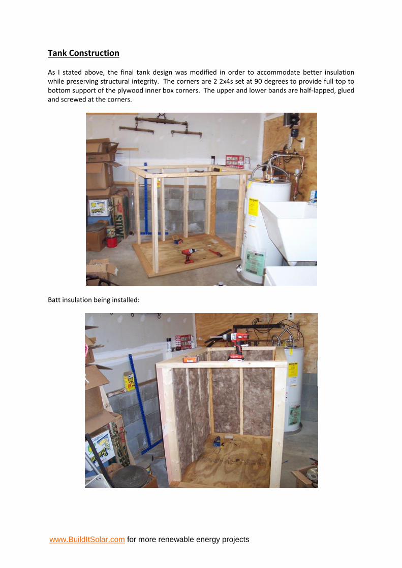
Tank Construction
As I stated above, the final tank design was modified in order to accommodate better insulation while preserving structural integrity. The corners are 2 2x4s set at 90 degrees to provide full top to bottom support of the plywood inner box corners. The upper and lower bands are half-lapped, glued and screwed at the corners.
Batt insulation being installed:

www.BuildItSolar.com for more renewable energy projects
Above is the finished carpentry on the tank. The bottom and side walls are ¾” underlayment plywood. There is a 5mm luaun plywood cover on the outside to dress it up a bit.
Unfortunately, I did not take any pictures of installing the polyisocyanurate board in the tank, but it’s there. There is no easy way to install the EPDM liner. You just have to jump in and do the best you can. Gary has very good instructions on this on the BIS website. Just be careful to leave enough slack in the tank so that there is no bridging when you fill it with water.

www.BuildItSolar.com for more renewable energy projects
Speaking of water, here is the partial fill, and you can also see the composite deck boards installed around the rim. Plenty of silicone caulk is the order of the day here.
And here is the completed tank:
www.BuildItSolar.com for more renewable energy projects
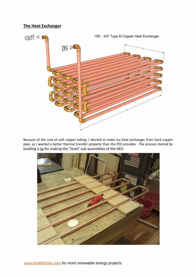
The Heat Exchanger
Because of the cost of soft copper tubing, I elected to make my heat exchanger from hard copper pipe, as I wanted a better thermal transfer property than the PEX provides. The process started by
building a jig for making the "level" sub-assemblies of the HEX:

www.BuildItSolar.com for more renewable energy projects
After several hours and repeating the process 5 times, I then stacked the assemblies and connected them together:
Here is the completed heat exchanger ready to be dropped into the tank (suspended actually, it sits in the top half of the tank).

www.BuildItSolar.com for more renewable energy projects
And here is the HEX all installed in the tank:
Installing the Collectors
For our collectors, we chose the Alternate Energy Technologies AE-40 flat plate collectors. The design calls for two 40 square foot collectors for a total of 80 square feet, or approximately 1 square foot of collector per 2.5 gallons of storage capacity. The collectors weigh in at 150 pounds each, so I designed a ramp system and used some old roller blade wheels I had to construct 4 “trucks”, which were then mounted to the collectors using the AET AE-SM mount brackets.

www.BuildItSolar.com for more renewable energy projects
Enlisting the aid of 2 of my ham radio friends, this made rolling the collectors right up onto the roof a relatively simple task. Fortunately, the Quick Mount PV mounts installed by the roofers months before were near-perfectly positioned for the collector mounts to drop right in place. The mounts were placed so that the collectors orient with approximately 3/16” per foot pitch for correct drainback.

www.BuildItSolar.com for more renewable energy projects
All piping is ¾” copper pipe and insulated with Armaflex pipe insulation. The supply and return pipes drop through a coolie cap flashing, down through a knee wall in the room over garage and then out of the wall in the garage to the storage tank. All piping is pitched at about ¼” per foot toward the tank.
The Controller
While the controllers by Steca et al are all very good, I found them insufficient for what I wanted to do with the system. Data logging and future expansion where key features I wanted in a controller. Being able to log data and plot it in order to determine performance and solar fraction was very important. I also wanted to be able to have the capacity to control radiant floor at such time as we decide to implement that. I chose the MAXDTC8 controller by mydtcstore.com. Brian designed and builds these units in a small company and his support is very good. Every question I had was quickly answered and I am impressed with the unit so far. It is not a “finished” product in that it does not have a custom case – more just a circuit board – but all of the functionality I needed is there.

www.BuildItSolar.com for more renewable energy projects
This is my implementation of the MAXDTC8 (I call it Max). The 8 10k thermistor inputs at the top left are wired out to barrier strips just to the left of the wire chase at left, where the sensor runs come into the backplane. I also wired out the 4 “special” inputs at the upper right to the barrier strips for future use, though I do not use them currently. Brian has an insolation sensor for sale which I wish now I had bought and will likely add to the system in the near future. A computer can be connected to the DB9 connector at lower right for configuring the unit and downloading the logs.
Here is a screen shot of the TeraTerm data connection from my laptop showing the differential control rule and the first section of a logging run:

www.BuildItSolar.com for more renewable energy projects
Performance
The system was placed in service at around 2:00 pm on Easter Sunday 2014. The day was partly cloudy and not much time in the day left for collection, but even still we managed to raise the storage tank from 60oF to 70oF in a couple of hours.
Monday April 21 was a nice sunny day and our first full day of collection. We raised the tank from 68oF at the start of the day to 111oF degrees by the end of the day, for about 73,780 BTUs of stored energy. The pump ran for a total of 5.1 hours and consumed about 0.23 kWH of energy.
Tuesday was also a nice day up until about 3:30 when the cloud cover moved in. Overnight the storage tank dropped from 111oF to 106oF, accounted for by my son taking a late evening shower and drawing some heat off the tank, but I still need to insulate the piping around the tank and secure the lid down tighter. The tank went from 106oF to 135oF during the day, for around 49,750 BTUs collected.
Wednesday again was a nice day. The tank started out at 132oF for an overnight loss of 3 degrees – there were no extended draws on Tuesday evening. At 1:27 PM the tank reached it’s 150 degree setpoint and the pump did not run again the rest of the day. Yippee! We made it to the design setpoint!

www.BuildItSolar.com for more renewable energy projects
The current settings on Max are On at 18oF differential and Off at 5oF differential. The seemingly excessive cycling of the pump on the 22nd would seem to indicate that the Off differential might need to be reduced to 2oF or 3oF.
Costs
Collector roof mounts and pipe flashing $ 298.07
Heat exchanger materials $ 299.61
Grundfos Alpha, tempering valve & isolation valves $ 392.85
Controller & thermocouples $ 255.00
EPDM liner 15' x 15' $ 177.43
Tank construction $ 341.24
AE-40 collectors $ 1,797.76
Miscellaneous plumbing materials & supplies $ 250.33
Total cost $ 3,812.29
Budget $ 4,000.00
Conclusion
Cost of materials: $3812.29. Labor invested: close to 100 hours. Satisfaction of having “done-it-myself” and getting “free” hot water – priceless.