how to make a pogo pin test jig - adafruit
TRANSCRIPT

How to Make a Pogo Pin Test Jig
Created by Tyler Cooper
https://learn.adafruit.com/how-to-make-a-pogo-pin-test-jig
Last updated on 2021-11-15 05:53:04 PM EST
©Adafruit Industries Page 1 of 11

3
3
5
8
9
10
11
Table of Contents
Overview
Preparation
Arduino Shield Jigs
The Code
Testing
Advanced Pogo Jigs
Support Forums
©Adafruit Industries Page 2 of 11
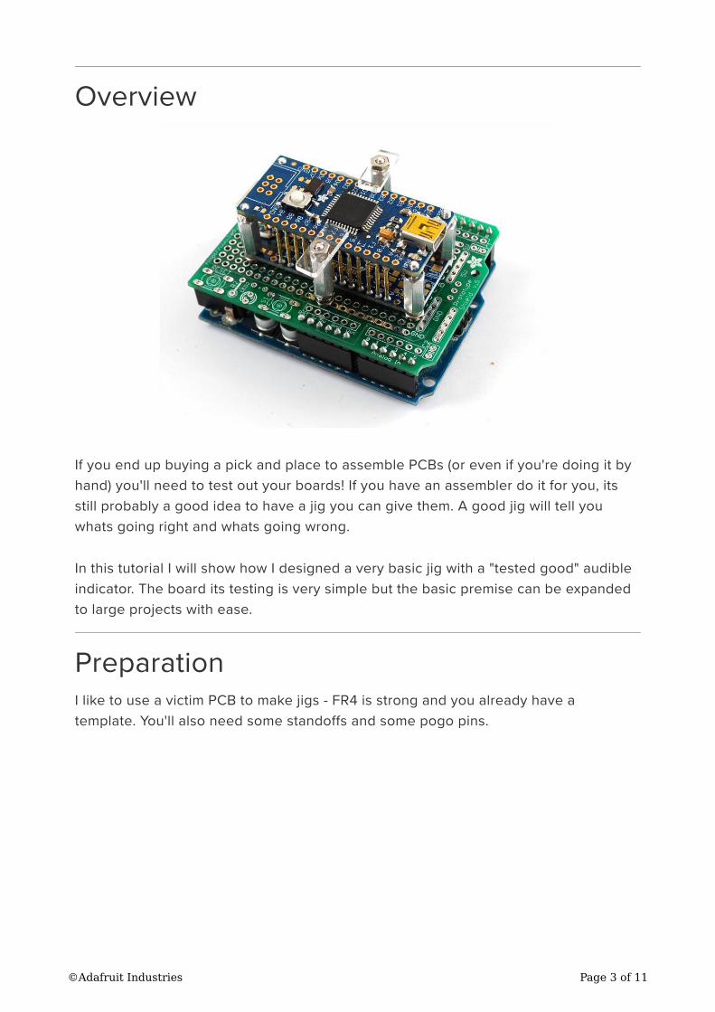
Overview
If you end up buying a pick and place to assemble PCBs (or even if you're doing it by
hand) you'll need to test out your boards! If you have an assembler do it for you, its
still probably a good idea to have a jig you can give them. A good jig will tell you
whats going right and whats going wrong.
In this tutorial I will show how I designed a very basic jig with a "tested good" audible
indicator. The board its testing is very simple but the basic premise can be expanded
to large projects with ease.
Preparation
I like to use a victim PCB to make jigs - FR4 is strong and you already have a
template. You'll also need some standoffs and some pogo pins.
©Adafruit Industries Page 3 of 11
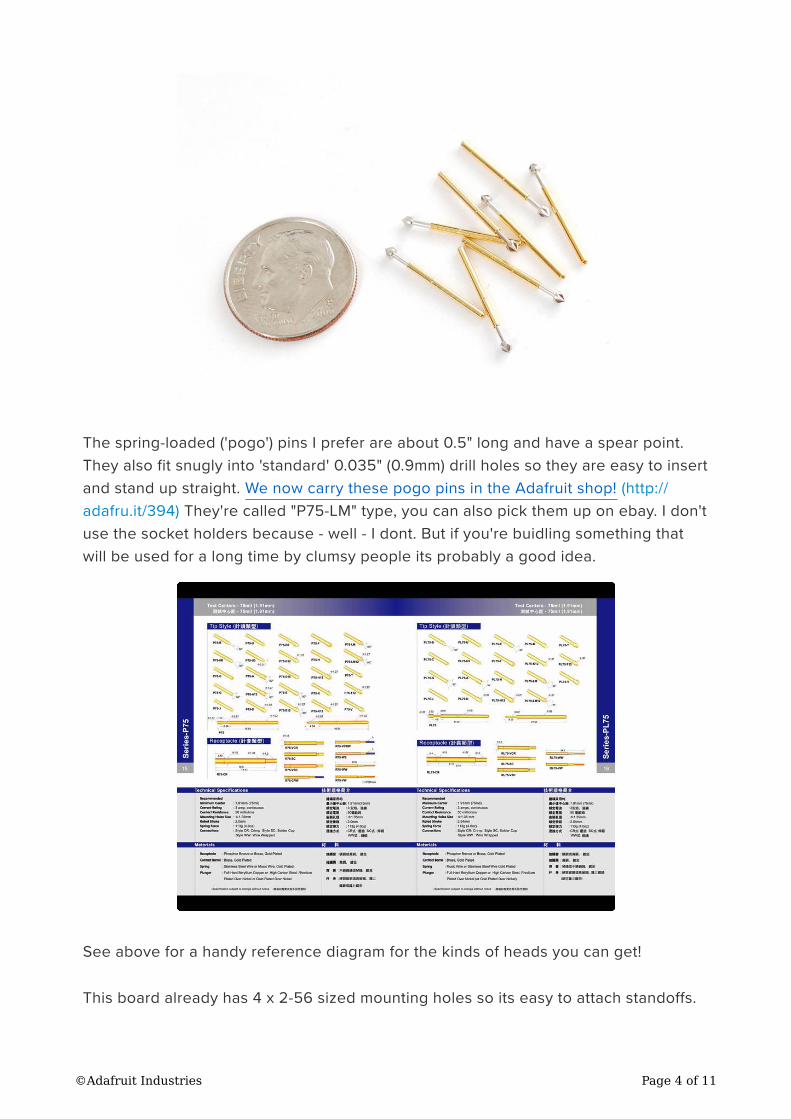
The spring-loaded ('pogo') pins I prefer are about 0.5" long and have a spear point.
They also fit snugly into 'standard' 0.035" (0.9mm) drill holes so they are easy to insert
and stand up straight. We now carry these pogo pins in the Adafruit shop! (http://
adafru.it/394) They're called "P75-LM" type, you can also pick them up on ebay. I don't
use the socket holders because - well - I dont. But if you're buidling something that
will be used for a long time by clumsy people its probably a good idea.
See above for a handy reference diagram for the kinds of heads you can get!
This board already has 4 x 2-56 sized mounting holes so its easy to attach standoffs.
©Adafruit Industries Page 4 of 11

Choose the standoffs so that the tips of the pogo pins are above the standoff part but
below the end of the screw.
Arduino Shield Jigs
I will be using an Arduino to make this jig (https://adafru.it/aIH). Arduinos are very
standard, easy to power and are a breeze for short projects like this. You'll also want a
proto shield PCB (https://adafru.it/aIH)
I think I'll put the victim...like this!
©Adafruit Industries Page 5 of 11
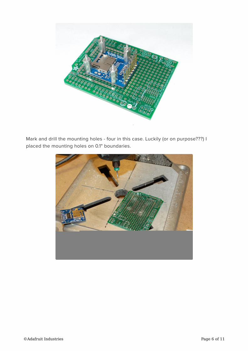
Mark and drill the mounting holes - four in this case. Luckily (or on purpose???) I
placed the mounting holes on 0.1" boundaries.
©Adafruit Industries Page 6 of 11

Solder wires from each pogo pin to a matching pin on the shield. For this SD card
interface I connected the SPI pins to the SPI port. Then the output of the 3.3v
regulator goes to an analog pin. I also connected the card detect pin up so I can tell
when a board is being tested.
A piezo buzzer is connected to pin #9 (underneath the PCB).
©Adafruit Industries Page 7 of 11

The Code
The code for the project is below and available on GitHub.
See the files for this project on
GitHub
https://adafru.it/Euf
/*
SD card breakout tester!
Uses fat16lib's fantastic FAT library
tests:
1. CD pin works (goes low when card inserted)
2. 3.3V LDO output is in proper range
3. Can communicate with card
*/
#include <SD.h>
Sd2Card card;
#define CD 15 // A1 (D15) -> CardDetect#define LDO 0 // analog 0
void setup() { // initialize the digital pin as an output:
Serial.begin(9600);
digitalWrite(CD, HIGH); // pull up on CD
}
void loop() {
Serial.println("waiting for SD card detect");
©Adafruit Industries Page 8 of 11
while (digitalRead(CD)) { Serial.print('.');
delay(100);
}
Serial.println("Detected Card!");
// first check 3.3V regulator
int a = analogRead(LDO); if ((a > 710) || (a < 650)) { // LDO not in the right range
Serial.println(a);
return; }
Serial.println("3.3V LDO ok");
// try to talk to the card
uint8_t r = card.init(1); if (!r) { // failed to talk to SD card :(
Serial.println(r, DEC);
return; }
Serial.println("Card interface ok");
// beep to indicate all is good
tone(9, 4000, 500);
delay(1000);
}
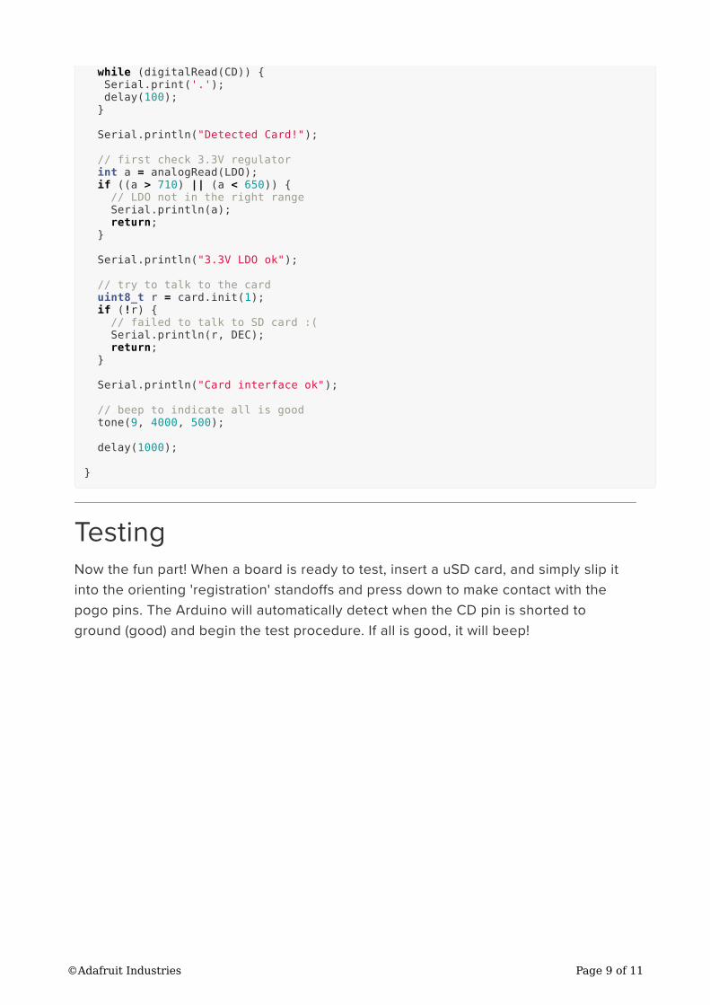
Testing
Now the fun part! When a board is ready to test, insert a uSD card, and simply slip it
into the orienting 'registration' standoffs and press down to make contact with the
pogo pins. The Arduino will automatically detect when the CD pin is shorted to
ground (good) and begin the test procedure. If all is good, it will beep!
©Adafruit Industries Page 9 of 11

Beep!
Advanced Pogo Jigs
For more complicated projects, you may need to have a complicated testing
procedure in which case we can make multi-step testers that also keep the PCB held
down with little ears!
©Adafruit Industries Page 10 of 11

(We totally saw this and stole the idea from someone online but we can't find the link
anymore, sorry!)
The plastic pieces hold down the PCB against the pogo bed. This tester, when used
with a little batch script, performs the following test:
Reprograms the board's fuses and flash with a bootloader (via the ISP port). For
this part we're using the Arduino as an ISP programmer (there's a sketch that
does this)
The computer then bootloads (via USB) a pin-by-pin testing program
Once the board indicates the test completed, the computer erases the testing
program
Support Forums
Support Forums (https://adafru.it/forums)
1.
2.
3.
©Adafruit Industries Page 11 of 11