12mm led pixels - adafruit - adafruit learning system
TRANSCRIPT
12mm LED Pixels
Created by Phillip Burgess
https://learn.adafruit.com/12mm-led-pixels
Last updated on 2021-11-15 05:49:13 PM EST
©Adafruit Industries Page 1 of 24
3
6
6
8
8
11
12
12
13
14
15
15
16
16
17
17
17
18
19
19
19
19
20
20
21
22
23
24
Table of Contents
Overview
Project Ideas
Power
• Tips for powering pixel strands:
Arduino Wiring
• Connecting to Arduino
Arduino Code
• Install Arduino Libraries
• Example Code
CircuitPython and Python Wiring
• CircuitPython Wiring
• Python Wiring
CircuitPython and Python Setup
• CircuitPython Setup
• Python Setup
CircuitPython and Python Usage
• Initialization
• Showing Changes
• Filling All Lights At Once
• Setting an individual LED
• Setting Multiple Values
• Getting a Value
• Setting the Brightness
• Full Example Code
Troubleshooting
Dimensions
• “Bullet” Pixels
• “Square” Pixels
©Adafruit Industries Page 2 of 24
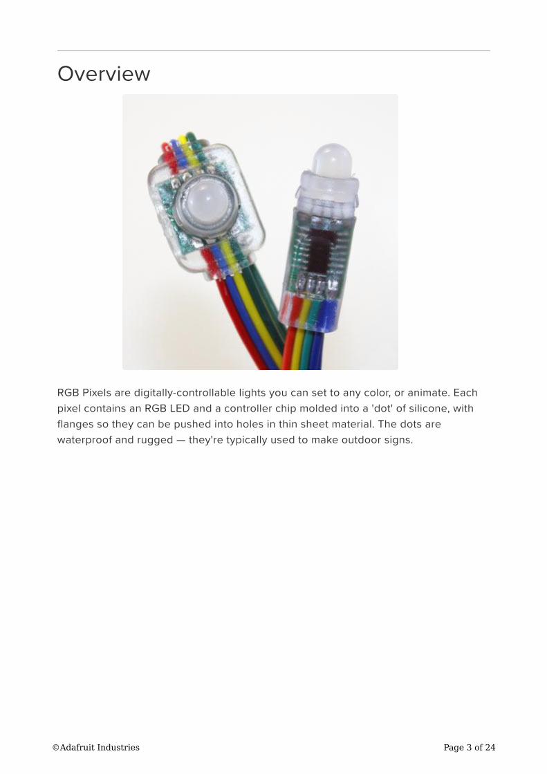
Overview
RGB Pixels are digitally-controllable lights you can set to any color, or animate. Each
pixel contains an RGB LED and a controller chip molded into a 'dot' of silicone, with
flanges so they can be pushed into holes in thin sheet material. The dots are
waterproof and rugged — they're typically used to make outdoor signs.
©Adafruit Industries Page 3 of 24
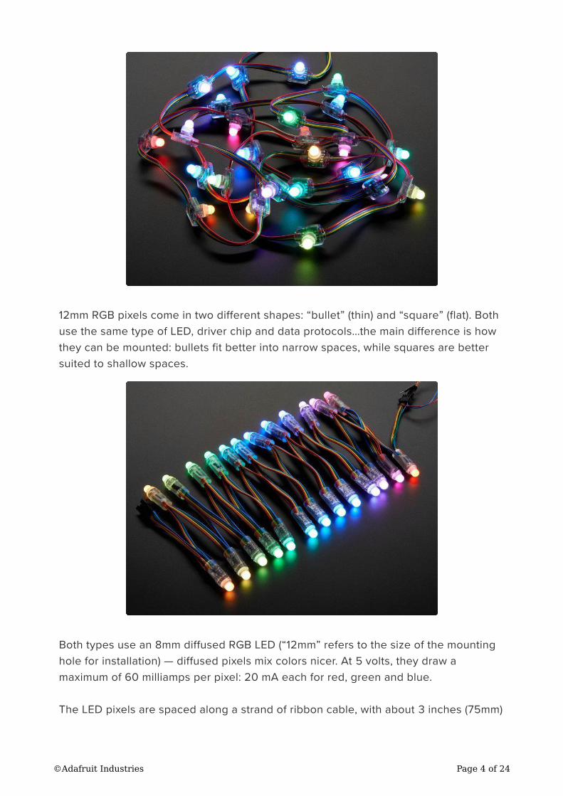
12mm RGB pixels come in two different shapes: “bullet” (thin) and “square” (flat). Both
use the same type of LED, driver chip and data protocols…the main difference is how
they can be mounted: bullets fit better into narrow spaces, while squares are better
suited to shallow spaces.
Both types use an 8mm diffused RGB LED (“12mm” refers to the size of the mounting
hole for installation) — diffused pixels mix colors nicer. At 5 volts, they draw a
maximum of 60 milliamps per pixel: 20 mA each for red, green and blue.
The LED pixels are spaced along a strand of ribbon cable, with about 3 inches (75mm)
©Adafruit Industries Page 4 of 24
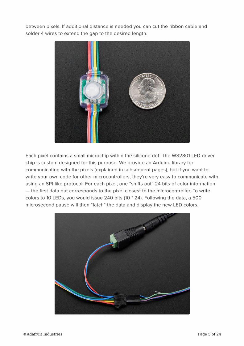
between pixels. If additional distance is needed you can cut the ribbon cable and
solder 4 wires to extend the gap to the desired length.
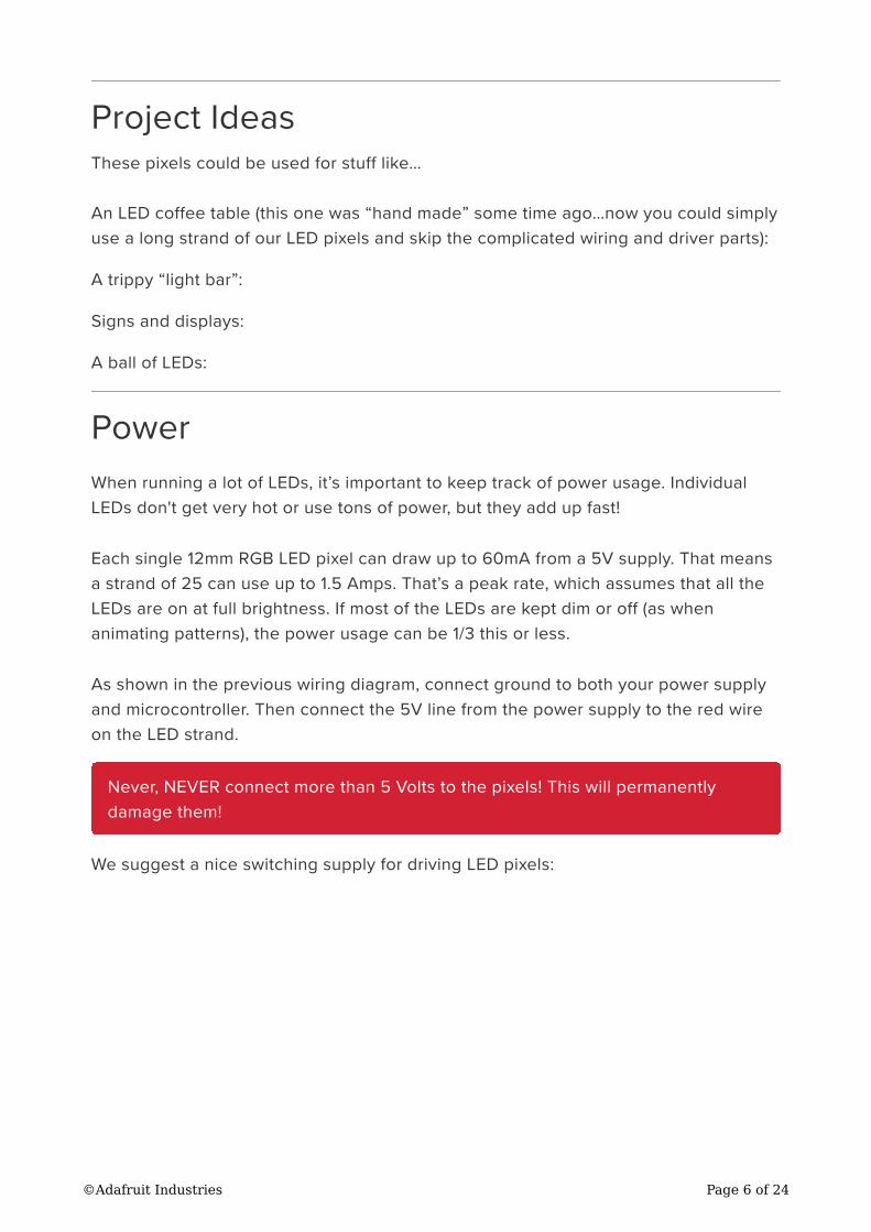
Each pixel contains a small microchip within the silicone dot. The WS2801 LED driver
chip is custom designed for this purpose. We provide an Arduino library for
communicating with the pixels (explained in subsequent pages), but if you want to
write your own code for other microcontrollers, they’re very easy to communicate with
using an SPI-like protocol. For each pixel, one “shifts out” 24 bits of color information
— the first data out corresponds to the pixel closest to the microcontroller. To write
colors to 10 LEDs, you would issue 240 bits (10 * 24). Following the data, a 500
microsecond pause will then “latch” the data and display the new LED colors.
©Adafruit Industries Page 5 of 24
Project Ideas
These pixels could be used for stuff like…
An LED coffee table (this one was “hand made” some time ago…now you could simply
use a long strand of our LED pixels and skip the complicated wiring and driver parts):
A trippy “light bar”:
Signs and displays:
A ball of LEDs:
Power
When running a lot of LEDs, it’s important to keep track of power usage. Individual
LEDs don't get very hot or use tons of power, but they add up fast!
Each single 12mm RGB LED pixel can draw up to 60mA from a 5V supply. That means
a strand of 25 can use up to 1.5 Amps. That’s a peak rate, which assumes that all the
LEDs are on at full brightness. If most of the LEDs are kept dim or off (as when
animating patterns), the power usage can be 1/3 this or less.
As shown in the previous wiring diagram, connect ground to both your power supply
and microcontroller. Then connect the 5V line from the power supply to the red wire
on the LED strand.
We suggest a nice switching supply for driving LED pixels:
Never, NEVER connect more than 5 Volts to the pixels! This will permanently
damage them!
©Adafruit Industries Page 6 of 24
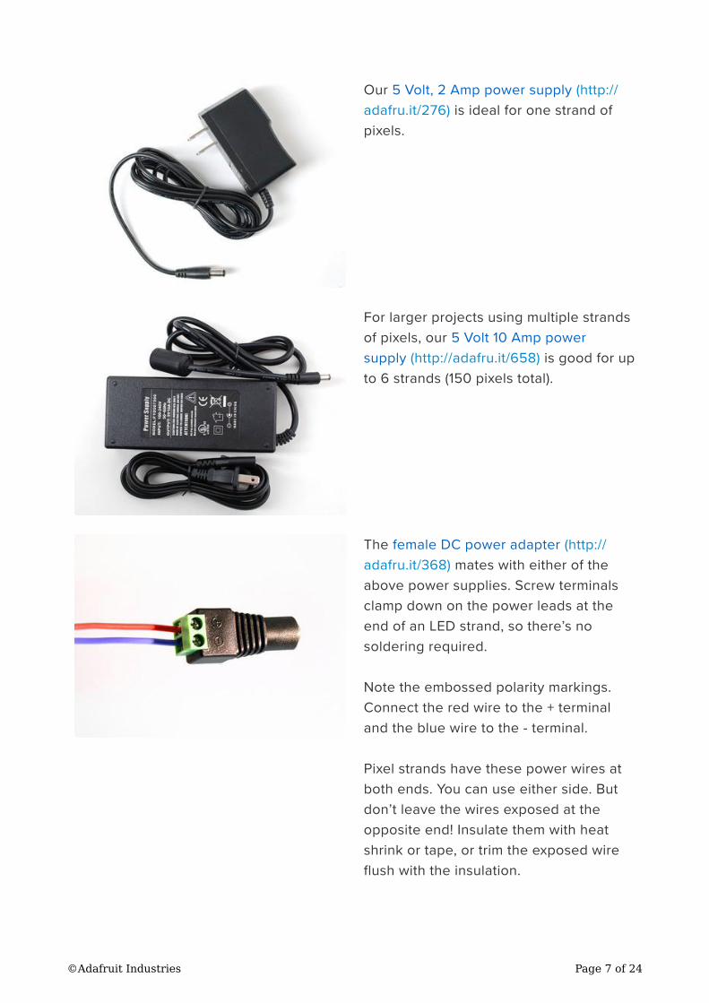
Our 5 Volt, 2 Amp power supply (http://
adafru.it/276) is ideal for one strand of
pixels.
For larger projects using multiple strands
of pixels, our 5 Volt 10 Amp power
supply (http://adafru.it/658) is good for up
to 6 strands (150 pixels total).
The female DC power adapter (http://
adafru.it/368) mates with either of the
above power supplies. Screw terminals
clamp down on the power leads at the
end of an LED strand, so there’s no
soldering required.
Note the embossed polarity markings.
Connect the red wire to the + terminal
and the blue wire to the - terminal.
Pixel strands have these power wires at
both ends. You can use either side. But
don’t leave the wires exposed at the
opposite end! Insulate them with heat
shrink or tape, or trim the exposed wire
flush with the insulation.
©Adafruit Industries Page 7 of 24
Tips for powering pixel strands:
When linking multiple strands together, power should be split and applied to ea
ch strand. If you try to power too many LEDs from just one end of the strand,
they’ll start to “brown out” the further they are from the power supply.
Strands can be powered from either end — “input” and “output” doesn’t apply to
power, only the data signals from the microcontroller.
If the 10 Amp power supply isn’t large enough for your project, a slightly
modified ATX computer power supply (https://adafru.it/aHR) can provide 30
Amps to power upwards of 500 pixels!
Generally speaking, you should not try to power an LED strand from the
Arduino’s 5V line. This is okay if just a few pixels are lit, but is not adequate for
driving a full strand.
For a standalone application (not USB connected to a computer), you can power
the Arduino from the same regulated 5V supply as the LEDs — connect to the
5V pin on the Arduino, not Vin, and don’t use the DC jack on the Arduino.
Remember to insulate or trim any unused, exposed power wires!
Arduino Wiring
The “magic” of these pixels is that they're digitally controlled…even though there are
only two control lines, you can have as many pixels as you’d like in a single long
strand, yet each remains independently controllable.
Though it looks like the 4-conductor ribbon cable is continuous, it isn't! The pixels
have a distinct “in” and “out” side. Data from the microcontroller arrives on the input
side, where it’s received by the driver chip. The output side then connects to the input
of the next pixel, all the way down the line.
•
•
•
•
•
•
EARLIER VERSIONS OF THESE PIXELS USED A DIFFERENT DRIVER CHIP AND/
OR WIRING COLORS. ANYTHING PURCHASED AFTER AUGUST 2011 SHOULD
MATCH THE FOLLOWING DECRIPTION. We initially sold LEDs in this form factor
using the LPD6803 driver chip (BEFORE August 2011). If you are using those
pixels, please use the 20mm pixel tutorial (www.ladyada.net/products/
pixel20mm), using the wiring and code from that page — nothing further here
applies. After switching to the WS2801 chip, the first batch used different wire
colors, but is functionally the same as described below.
©Adafruit Industries Page 8 of 24
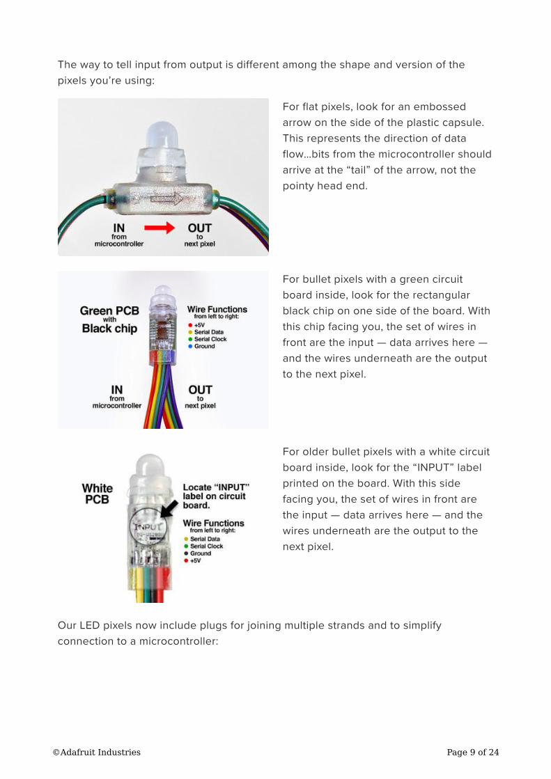
The way to tell input from output is different among the shape and version of the
pixels you’re using:
For flat pixels, look for an embossed
arrow on the side of the plastic capsule.
This represents the direction of data
flow…bits from the microcontroller should
arrive at the “tail” of the arrow, not the
pointy head end.
For bullet pixels with a green circuit
board inside, look for the rectangular
black chip on one side of the board. With
this chip facing you, the set of wires in
front are the input — data arrives here —
and the wires underneath are the output
to the next pixel.
For older bullet pixels with a white circuit
board inside, look for the “INPUT” label
printed on the board. With this side
facing you, the set of wires in front are
the input — data arrives here — and the
wires underneath are the output to the
next pixel.
Our LED pixels now include plugs for joining multiple strands and to simplify
connection to a microcontroller:
©Adafruit Industries Page 9 of 24
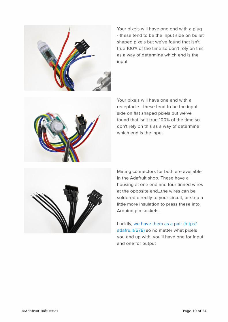
Your pixels will have one end with a plug
- these tend to be the input side on bullet
shaped pixels but we've found that isn't
true 100% of the time so don't rely on this
as a way of determine which end is the
input
Your pixels will have one end with a
receptacle - these tend to be the input
side on flat shaped pixels but we've
found that isn't true 100% of the time so
don't rely on this as a way of determine
which end is the input
Mating connectors for both are available
in the Adafruit shop. These have a
housing at one end and four tinned wires
at the opposite end…the wires can be
soldered directly to your circuit, or strip a
little more insulation to press these into
Arduino pin sockets.
Luckily, we have them as a pair (http://
adafru.it/578) so no matter what pixels
you end up with, you'll have one for input
and one for output
©Adafruit Industries Page 10 of 24
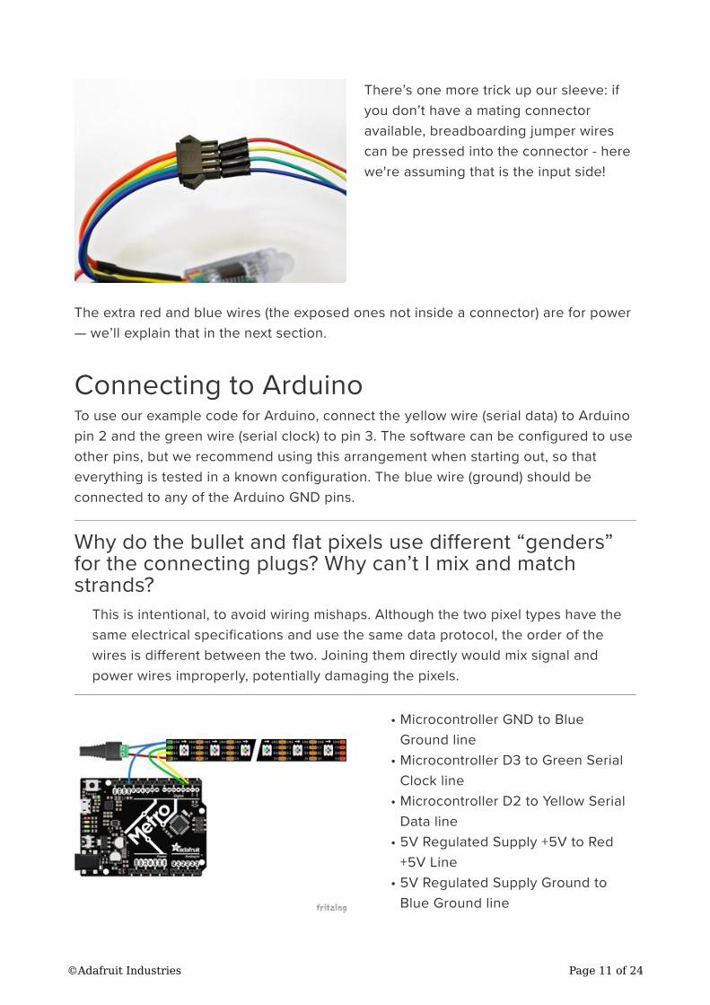
There’s one more trick up our sleeve: if
you don’t have a mating connector
available, breadboarding jumper wires
can be pressed into the connector - here
we're assuming that is the input side!
The extra red and blue wires (the exposed ones not inside a connector) are for power
— we’ll explain that in the next section.
Connecting to Arduino
To use our example code for Arduino, connect the yellow wire (serial data) to Arduino
pin 2 and the green wire (serial clock) to pin 3. The software can be configured to use
other pins, but we recommend using this arrangement when starting out, so that
everything is tested in a known configuration. The blue wire (ground) should be
connected to any of the Arduino GND pins.
Why do the bullet and flat pixels use different “genders”
for the connecting plugs? Why can’t I mix and match
strands?
This is intentional, to avoid wiring mishaps. Although the two pixel types have the
same electrical specifications and use the same data protocol, the order of the
wires is different between the two. Joining them directly would mix signal and
power wires improperly, potentially damaging the pixels.
Microcontroller GND to Blue
Ground line
Microcontroller D3 to Green Serial
Clock line
Microcontroller D2 to Yellow Serial
Data line
5V Regulated Supply +5V to Red
+5V Line
5V Regulated Supply Ground to
Blue Ground line
•
•
•
•
•
©Adafruit Industries Page 11 of 24
Download Fritzing Diagram
https://adafru.it/GCe
Arduino Code
Install Arduino Libraries
We have example code ready to go for use with the LEDs. It's written for Arduino,
which should be portable to any microcontroller by adapting the C++ source.
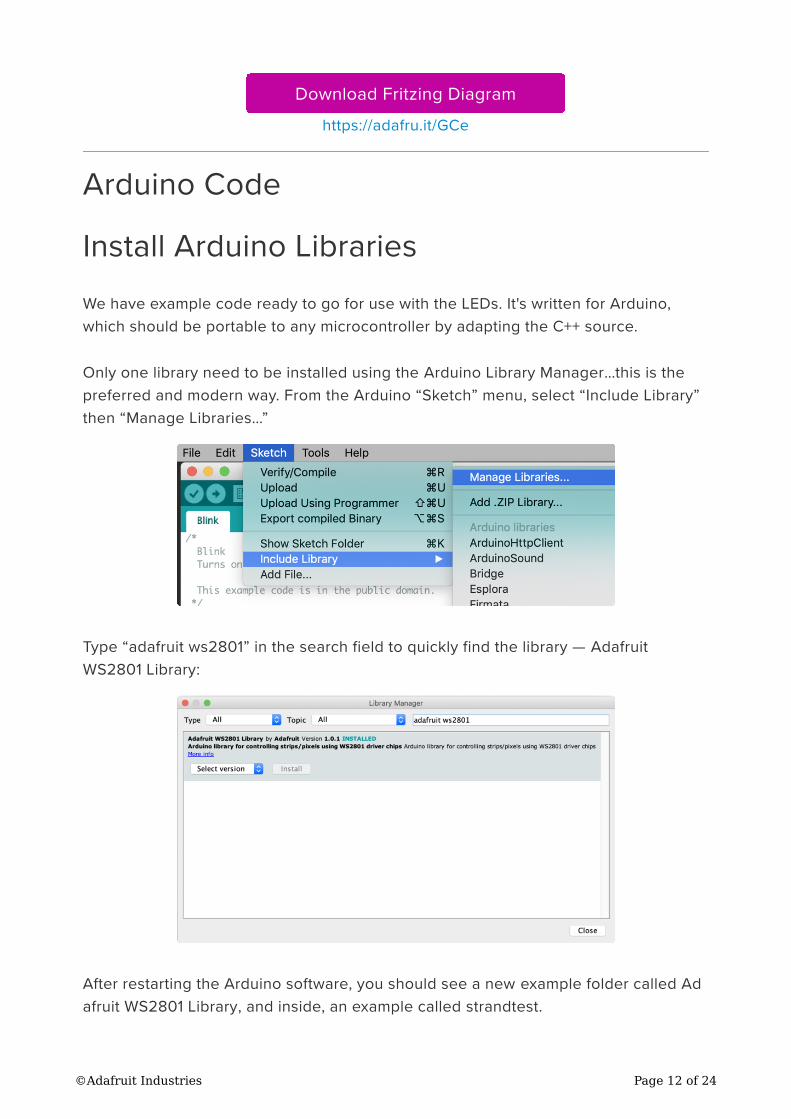
Only one library need to be installed using the Arduino Library Manager…this is the
preferred and modern way. From the Arduino “Sketch” menu, select “Include Library”
then “Manage Libraries…”
Type “adafruit ws2801” in the search field to quickly find the library — Adafruit
WS2801 Library:
After restarting the Arduino software, you should see a new example folder called Ad
afruit WS2801 Library, and inside, an example called strandtest.
©Adafruit Industries Page 12 of 24
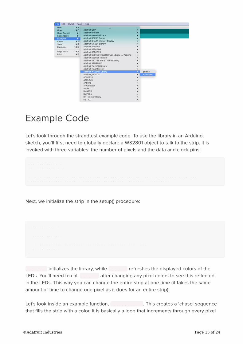
Example Code
Let's look through the strandtest example code. To use the library in an Arduino
sketch, you'll first need to globally declare a WS2801 object to talk to the strip. It is
invoked with three variables: the number of pixels and the data and clock pins:
int dataPin = 2;
int clockPin = 3;
// Set the first variable to the NUMBER of pixels. 25 = 25 pixels in a row
Adafruit_WS2801 strip = Adafruit_WS2801(25, dataPin, clockPin);
Next, we initialize the strip in the setup() procedure:
void setup() {
strip.begin();
// Update LED contents, to start they are all 'off'
strip.show();
}
begin() initializes the library, while show() refreshes the displayed colors of the
LEDs. You'll need to call show() after changing any pixel colors to see this reflected
in the LEDs. This way you can change the entire strip at one time (it takes the same
amount of time to change one pixel as it does for an entire strip).
Let's look inside an example function, colorWipe() . This creates a 'chase' sequence
that fills the strip with a color. It is basically a loop that increments through every pixel
©Adafruit Industries Page 13 of 24
(which you can query with the numPixels() function) and sets the color of each
(incremented with i) to the value passed (c — colors are expressed as a 32-bit variable
type, though only the bottom 24 bits are used). The strip output is then updated
with show() . Finally there is some delay (otherwise this would happen instantly).
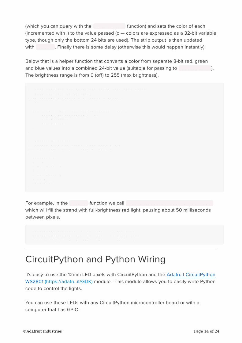
Below that is a helper function that converts a color from separate 8-bit red, green
and blue values into a combined 24-bit value (suitable for passing to colorWipe() ).
The brightness range is from 0 (off) to 255 (max brightness).
// fill the dots one after the other with said color
// good for testing purposes
void colorWipe(uint32_t c, uint8_t wait) {
int i;
for (i=0; i < strip.numPixels(); i++) {
strip.setPixelColor(i, c);
strip.show();
delay(wait);
}
}
/* Helper functions */
// Create a 24 bit color value from R,G,B
uint32_t Color(byte r, byte g, byte b)
{
uint32_t c;
c = r;
c <<= 8;
c |= g;
c <<= 8;
c |= b;
return c;
}
For example, in the loop() function we call colorWipe(Color(255, 0, 0), 50)
which will fill the strand with full-brightness red light, pausing about 50 milliseconds
between pixels.
colorWipe(Color(255, 0, 0), 50); // red fill
colorWipe(Color(0, 255, 0), 50); // green fill
colorWipe(Color(0, 0, 255), 50); // blue fill
CircuitPython and Python Wiring
It's easy to use the 12mm LED pixels with CircuitPython and the Adafruit CircuitPython
WS2801 (https://adafru.it/GDK) module. This module allows you to easily write Python
code to control the lights.
You can use these LEDs with any CircuitPython microcontroller board or with a
computer that has GPIO.
©Adafruit Industries Page 14 of 24
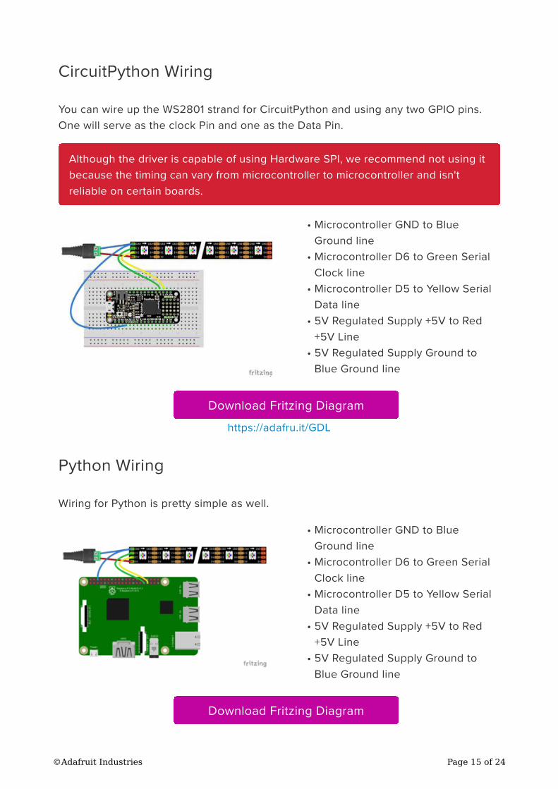
CircuitPython Wiring
You can wire up the WS2801 strand for CircuitPython and using any two GPIO pins.
One will serve as the clock Pin and one as the Data Pin.
Microcontroller GND to Blue
Ground line
Microcontroller D6 to Green Serial
Clock line
Microcontroller D5 to Yellow Serial
Data line
5V Regulated Supply +5V to Red
+5V Line
5V Regulated Supply Ground to
Blue Ground line
Download Fritzing Diagram
https://adafru.it/GDL
Python Wiring
Wiring for Python is pretty simple as well.
Microcontroller GND to Blue
Ground line
Microcontroller D6 to Green Serial
Clock line
Microcontroller D5 to Yellow Serial
Data line
5V Regulated Supply +5V to Red
+5V Line
5V Regulated Supply Ground to
Blue Ground line
Download Fritzing Diagram
Although the driver is capable of using Hardware SPI, we recommend not using it
because the timing can vary from microcontroller to microcontroller and isn't
reliable on certain boards.
•
•
•
•
•
•
•
•
•
•
©Adafruit Industries Page 15 of 24
https://adafru.it/Nsc
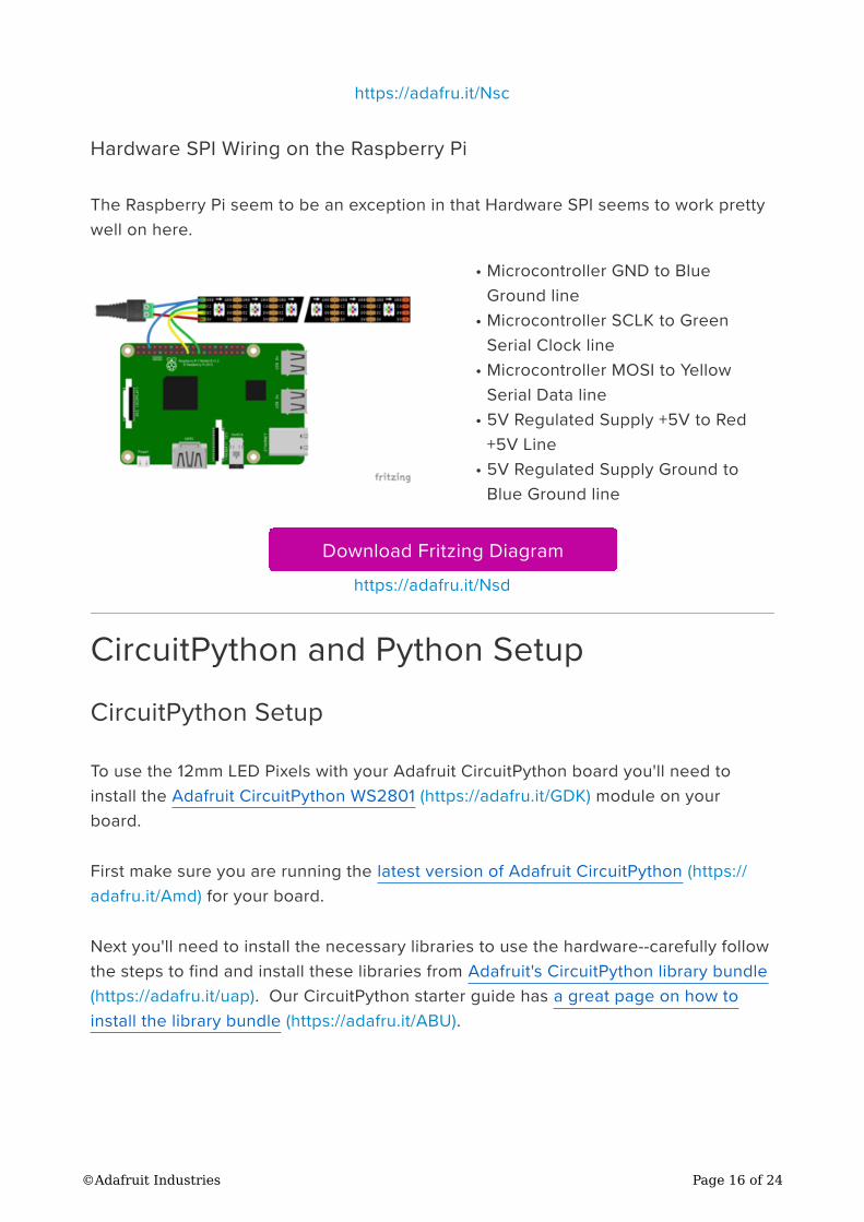
Hardware SPI Wiring on the Raspberry Pi
The Raspberry Pi seem to be an exception in that Hardware SPI seems to work pretty
well on here.
Microcontroller GND to Blue
Ground line
Microcontroller SCLK to Green
Serial Clock line
Microcontroller MOSI to Yellow
Serial Data line
5V Regulated Supply +5V to Red
+5V Line
5V Regulated Supply Ground to
Blue Ground line
Download Fritzing Diagram
https://adafru.it/Nsd
CircuitPython and Python Setup
CircuitPython Setup
To use the 12mm LED Pixels with your Adafruit CircuitPython board you'll need to
install the Adafruit CircuitPython WS2801 (https://adafru.it/GDK) module on your
board.
First make sure you are running the latest version of Adafruit CircuitPython (https://
adafru.it/Amd) for your board.
Next you'll need to install the necessary libraries to use the hardware--carefully follow
the steps to find and install these libraries from Adafruit's CircuitPython library bundle
(https://adafru.it/uap). Our CircuitPython starter guide has a great page on how to
install the library bundle (https://adafru.it/ABU).
•
•
•
•
•
©Adafruit Industries Page 16 of 24
If you choose, you can manually install the libraries individually on your board:
adafruit_ws2801
Before continuing make sure your board's lib folder or root filesystem has the
adafruit_ws2801.mpy file copied over. You should now be ready to go!
Python Setup
You'll need to install the Adafruit_Blinka library that provides the CircuitPython
support in Python. This may also require enabling SPI on your platform and verifying
you are running Python 3. Since each platform is a little different, and Linux changes
often, please visit the CircuitPython on Linux guide to get your computer ready (https
://adafru.it/BSN)!
Python Installation of WS2801 Library
Once that's done, from your command line run the following command:
sudo pip3 install adafruit-circuitpython-ws2801
If your default Python is version 3 you may need to run 'pip' instead. Just make sure
you aren't trying to use CircuitPython on Python 2.x, it isn't supported!
If that complains about pip3 not being installed, then run this first to install it:
sudo apt-get install python3-pip
CircuitPython and Python Usage
The 12mm LED pixels are really easy to use with CircuitPython and the Adafruit
CircuitPython WS2801 (https://adafru.it/GDK) module.
Initialization
Whether you connected the LED Pixels to your microcontroller through the Hardware
SPI or Software SPI, initialization is about the same.
•
•
•
©Adafruit Industries Page 17 of 24
import boardimport adafruit_ws2801
odata = board.D5oclock = board.D6numleds = 25bright = 1.0leds = adafruit_ws2801.WS2801(oclock, odata, numleds, brightness=bright, auto_write=False)
In this example, we are using D5 and D6 , which are for driving it through software. If
we were driving it through hardware on the Raspberry Pi, we would use the following
Pins:
odata = board.MOSIoclock = board.SCK
Make sure the number of LEDs corresponds to the actual number that you had. For
instance, if you had two strands of 25 LEDs, that's 50 LEDs.
You can adjust the brightness by changing the number between 0 and 1.0. Setting it
lower than one requires a little more processor power because to achieve that effect,
they need to rapidly turned on and off.
If you didn't want to have to call show() in order to update the strand, you could
either set auto_write to True or remove it from the initializer altogether.
Showing Changes
If auto_write is set to False, you will need to call show() in order to show any
changes you made to the lights:
leds[0] = 0xff0000leds.show()
Although the driver is capable of using Hardware SPI, we recommend not using it
because the timing can vary from microcontroller to microcontroller and isn't
reliable on certain boards.
©Adafruit Industries Page 18 of 24
Filling All Lights At Once
You can fill all the lights at once with the fill command. The color can either be a
tuple of Red, Green, and Blue as a number between 0-255 each, a hexadecimal
number in the format of 0xRRGGBB:
# Use an RGB Tuple
leds.fill((255, 0, 0))
# Use a Hexidecimal Value
leds.fill(0xff0000)
Setting an individual LED
You can set the value of a single LED by passing a color value as a tuple or
hexadecimal value to an index:
leds[0] = (0, 0, 255) # Set the first LED blue
leds[1] = 0x00ff00 # Set the second LED Green
Setting Multiple Values
You can set multiple values at the same time using a slice. For instance, if you wanted
to set the first three LEDs to Red, Green, and Blue, you could type the following:
leds[0:3] = ((255, 0, 0), (0, 255, 0),
(0, 0, 255))
Getting a Value
Just like you can set the LEDs, you can also read the current value of the LEDs. The
value will be returned as a Tuple:
leds[0] = 0xff0000leds[1] = 0x00ff00leds[2] = 0x0000ff
my_color = leds[0] # Returns (255, 0, 0)
my_colors = leds[0:3] # Returns [(255, 0, 0), (0, 255, 0), (0, 0, 255)]
©Adafruit Industries Page 19 of 24
Setting the Brightness
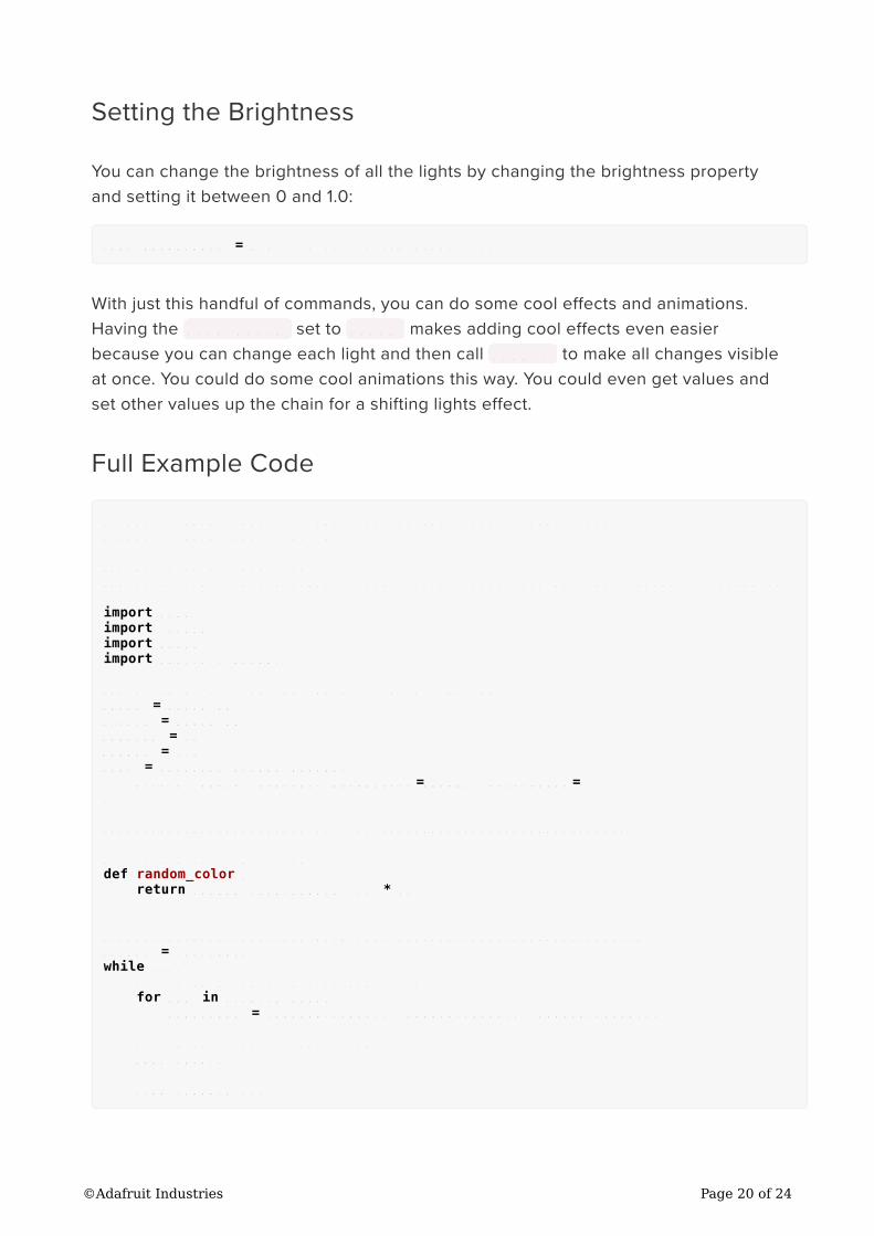
You can change the brightness of all the lights by changing the brightness property
and setting it between 0 and 1.0:
leds.brightness = 0.5 # Set to 50% Brightness
With just this handful of commands, you can do some cool effects and animations.
Having the auto_write set to False makes adding cool effects even easier
because you can change each light and then call show() to make all changes visible
at once. You could do some cool animations this way. You could even get values and
set other values up the chain for a shifting lights effect.
Full Example Code
# SPDX-FileCopyrightText: 2021 ladyada for Adafruit Industries
# SPDX-License-Identifier: MIT
### Based on example from
### https://github.com/adafruit/Adafruit_CircuitPython_DotStar/tree/master/examples
import timeimport randomimport boardimport adafruit_ws2801
### Example for a Feather M4 driving 25 12mm leds
odata = board.D5oclock = board.D6numleds = 25bright = 1.0leds = adafruit_ws2801.WS2801( oclock, odata, numleds, brightness=bright, auto_write=False)
######################### HELPERS ##############################
# a random color 0 -> 224
def random_color(): return random.randrange(0, 7) * 32
######################### MAIN LOOP ##############################
n_leds = len(leds)while True: # fill each led with a random color
for idx in range(n_leds): leds[idx] = (random_color(), random_color(), random_color())
# show all leds in led string
leds.show()
time.sleep(0.25)
©Adafruit Industries Page 20 of 24
Troubleshooting
How do I install the LEDs (physically)?
It's pretty easy! Simply drill a 12mm hole into any material up to 1.5mm/0.06" thick.
Then push the LED bulb first into the hole. It takes a little wiggling but there are
four flanges molded in so that you can 'push' them thru and the flanges will keep
the LED pixel in place
Many support issues arise from eager users getting ahead of themselves, changing
the code and wiring before confirming that all the pieces work in the standard
configuration. We recommend always starting out with the examples as shown. Use
the pinouts and wiring exactly as in the tutorial, and run the stock, unmodified
“strandtest” example sketch. Only then should you start switching things around.
Here are the most common issues and solutions…
The pixels are wired and powered exactly as in the
tutorial, the sketch compiles and uploads successfully, but
nothing happens.
Double-check all wiring. Are the clock and data wires swapped? Is ground
connected to the Arduino?
Confirm the Arduino is connected to the input end of the strand.
Check power supply polarity and voltage. Are + and – swapped? If you have a
multimeter, confirm 5V DC output (±10%) from the power supply.
Are the power wires at the opposite end of the strand insulated or trimmed?
They should not be left exposed where they might make contact with metal,
or each other.
Is the correct board type selected in the Arduino Tools→Board menu?
A few LEDs randomly turn on when power is applied, but
then nothing happens.
The power supply is probably OK. Check for any of the following:
Double-check all wiring. Are the clock and data wires swapped? Is ground
connected to the Arduino?
Confirm the Arduino is connected to the input end of the strand.
Is the correct board type selected in the Arduino Tools→Board menu?
Did the strandtest code successfully compile and upload?
•
•
•
•
•
•
•
•
•
©Adafruit Industries Page 21 of 24
Only the first few LEDs respond. The rest remain off or
flicker randomly.
Confirm that the number of LEDs in the Adafruit_WS2801() constructor match
the number of LEDs in the strand (both will be 25 if using the strandtest
example and a single strand of LEDs).
Inside each pixel there’s a small circuit board. Give the first bad pixel (and the
one immediately before it) a firm squeeze where the ribbon cable joins the
board — it may simply be a dodgy connection. If that works, you can either
cut out the offending pixel and join the two sub-strands, or arrange for a
replacement strand if new.
The LEDs flicker randomly, not the way they’re
programmed to.
Are the clock and data wires swapped? Is ground connected to the Arduino?
“White” LEDs are showing pink instead.
This can happen when trying to power too long of a strand from one end.
Voltage will drop along the length of the strand and the furthest pixels will
“brown out.” Connect power to 25 pixel strand.
Sketch will not compile: error message is
“Adafruit_WS2801 does not name a type”
Confirm the library is unzipped prior to installation.
Confirm the library is properly named and located. The folder should be
called Adafruit_WS2801, and placed inside your personal Documents/
Arduino/Libraries folder — inside the Arduino application folder!
After installation, the Arduino IDE needs to be restarted for new libraries to
be used.
Dimensions
There’s a fair amount of variance between pixels due to the rubbery, waterproof
coating. The figures given here are just guidelines, rounded up to the next whole
millimeter (except for the mounting hole diameter). Allow yourself some extra “wiggle
room” for spacing when planning an installation.
For mounting holes, 11.5 millimeters is a good guideline, or might go as narrow as 11
•
•
•
•
•
•
©Adafruit Industries Page 22 of 24
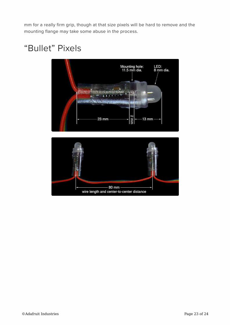
mm for a really firm grip, though at that size pixels will be hard to remove and the
mounting flange may take some abuse in the process.
“Bullet” Pixels
©Adafruit Industries Page 23 of 24
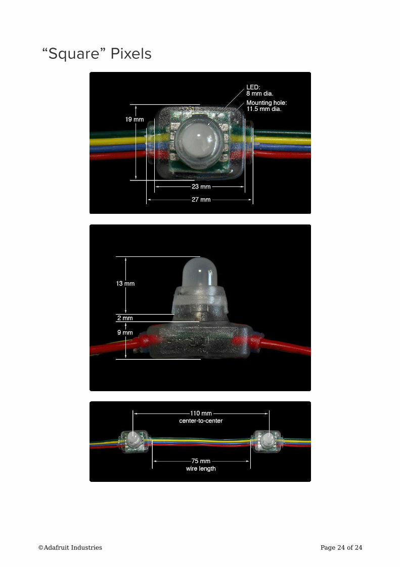
“Square” Pixels
©Adafruit Industries Page 24 of 24