how to implement state machines in your...
TRANSCRIPT
How to ImplementState Machines in Your FPGA
by Adam TaylorPrincipal EngineerEADS [email protected]
52 Xcell Journal Fourth Quarter 2012

FPGAs are often called upon to performsequence- and control-based actions such asimplementing a simple communication proto-col. For a designer, the best way to addressthese actions and sequences is by using a state
machine. State machines are logical constructs that transitionamong a finite number of states. A state machine will be inonly one state at a particular point in time. It will, however,move between states depending upon a number of triggers.
Theoretically, state machines are divided into two basicclasses—Moore and Mealy—that differ only in how theygenerate the state machine outputs. In a Moore type, thestate machine outputs are a function of the present stateonly. A classic example is a counter. In a Mealy statemachine, the outputs are a function of the present state andinputs. A classic example is the Richards controller (seehttp://en.wikipedia.org/wiki/Richards_controller).
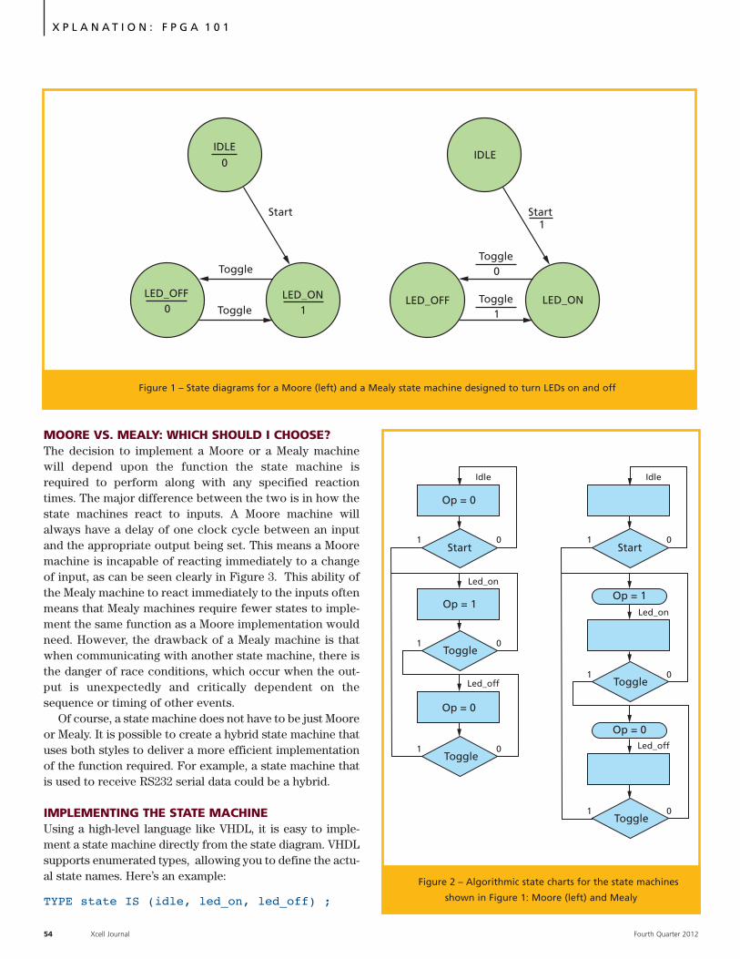
DEFINING A STATE MACHINEWhen faced with the task of defining a state machine, thefirst step is to develop a state diagram. A state diagramshows the states, the transitions between states and theoutputs from the state machine. Figure 1 shows two statediagrams, one for a Moore state machine (left) and theother for a Mealy state machine.
If you had to implement these diagrams in physical com-ponents (as engineers did before FPGAs were available),you would start by generating the present-state and next-state tables, and producing the logic required to implementthe state machine. However, as we will be using an FPGAfor implementation, we can work directly from the statetransition diagram.
ALGORITHMIC STATE DIAGRAMS While many state machines are designed using the state dia-gram approach shown in Figure 1, another method ofdescribing a state machine’s behavior is the algorithmicstate chart. This ASM chart (Figure 2) is much closer inappearance to a software-engineering flow chart. It consistsof three basic constructs:
1. State box, which is associated with the state nameand contains a list of the state outputs (Moore)
2. Decision box, which tests for a condition being trueand allows the next state to be determined
3. Conditional output box, which allows the statemachine to describe Mealy outputs dependent uponthe current state and inputs
Some engineers feel that a state machine described inASM format is easier to map to implementation in a hard-ware description language such as VHDL.
X P L A N A T I O N : F P G A 1 0 1
State machines are often the backbone of FPGA development. Choosing the right architecture and implementation methods will ensure that you obtain an optimal solution.
Fourth Quarter 2012 Xcell Journal 53
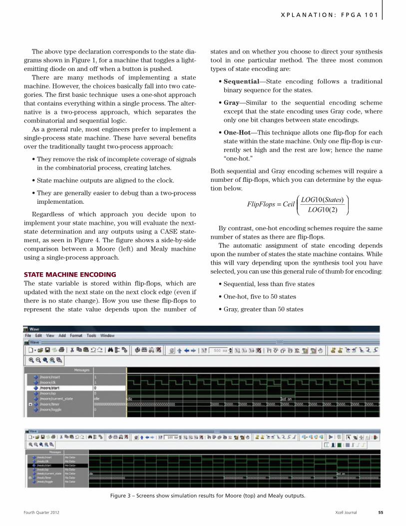
MOORE VS. MEALY: WHICH SHOULD I CHOOSE?The decision to implement a Moore or a Mealy machinewill depend upon the function the state machine isrequired to perform along with any specified reactiontimes. The major difference between the two is in how thestate machines react to inputs. A Moore machine willalways have a delay of one clock cycle between an inputand the appropriate output being set. This means a Mooremachine is incapable of reacting immediately to a changeof input, as can be seen clearly in Figure 3. This ability ofthe Mealy machine to react immediately to the inputs oftenmeans that Mealy machines require fewer states to imple-ment the same function as a Moore implementation wouldneed. However, the drawback of a Mealy machine is thatwhen communicating with another state machine, there isthe danger of race conditions, which occur when the out-put is unexpectedly and critically dependent on thesequence or timing of other events.
Of course, a state machine does not have to be just Mooreor Mealy. It is possible to create a hybrid state machine thatuses both styles to deliver a more efficient implementationof the function required. For example, a state machine thatis used to receive RS232 serial data could be a hybrid.
IMPLEMENTING THE STATE MACHINEUsing a high-level language like VHDL, it is easy to imple-ment a state machine directly from the state diagram. VHDLsupports enumerated types, allowing you to define the actu-al state names. Here’s an example:
TYPE state IS (idle, led_on, led_off) ;
54 Xcell Journal Fourth Quarter 2012
X P L A N A T I O N : F P G A 1 0 1
Start
Toggle
Toggle
LED_OFF LED_ON0
0
1
IDLE
Start
Toggle
LED_OFF LED_ON
0
IDLE
Toggle1
1
Op = 0
Op = 1
Op = 0
Start
Toggle
Toggle
1 0
1 0
1 0
Led_on
Idle
Led_off
Start
Toggle
Toggle
1 0
1 0
1 0
Led_on
Idle
Led_off
Op = 1
Op = 0
Figure 1 – State diagrams for a Moore (left) and a Mealy state machine designed to turn LEDs on and off
Figure 2 – Algorithmic state charts for the state machines
shown in Figure 1: Moore (left) and Mealy
X P L A N A T I O N : F P G A 1 0 1
Fourth Quarter 2012 Xcell Journal 55
The above type declaration corresponds to the state dia-grams shown in Figure 1, for a machine that toggles a light-emitting diode on and off when a button is pushed.
There are many methods of implementing a statemachine. However, the choices basically fall into two cate-gories. The first basic technique uses a one-shot approachthat contains everything within a single process. The alter-native is a two-process approach, which separates thecombinatorial and sequential logic.
As a general rule, most engineers prefer to implement asingle-process state machine. These have several benefitsover the traditionally taught two-process approach:
• They remove the risk of incomplete coverage of signalsin the combinatorial process, creating latches.
• State machine outputs are aligned to the clock.
• They are generally easier to debug than a two-processimplementation.
Regardless of which approach you decide upon toimplement your state machine, you will evaluate the next-state determination and any outputs using a CASE state-ment, as seen in Figure 4. The figure shows a side-by-sidecomparison between a Moore (left) and Mealy machineusing a single-process approach.
STATE MACHINE ENCODING The state variable is stored within flip-flops, which areupdated with the next state on the next clock edge (even ifthere is no state change). How you use these flip-flops torepresent the state value depends upon the number of
states and on whether you choose to direct your synthesistool in one particular method. The three most commontypes of state encoding are:
• Sequential—State encoding follows a traditionalbinary sequence for the states.
• Gray—Similar to the sequential encoding schemeexcept that the state encoding uses Gray code, whereonly one bit changes between state encodings.
• One-Hot—This technique allots one flip-flop for eachstate within the state machine. Only one flip-flop is cur-rently set high and the rest are low; hence the name“one-hot.”
Both sequential and Gray encoding schemes will require anumber of flip-flops, which you can determine by the equa-tion below.
By contrast, one-hot encoding schemes require the samenumber of states as there are flip-flops.
The automatic assignment of state encoding dependsupon the number of states the state machine contains. Whilethis will vary depending upon the synthesis tool you haveselected, you can use this general rule of thumb for encoding:
• Sequential, less than five states
• One-hot, five to 50 states
• Gray, greater than 50 states
⎟⎟⎠
⎞⎜⎜⎝
⎛=
)2(10)(10
LOGStatesLOG
CeilFlipFlops
Figure 3 – Screens show simulation results for Moore (top) and Mealy outputs.

In addition, you can also use the syn_encoding attributeto define the values of the state encoding directly. Forexample, suppose you desired to encode a three-statemachine using the following state encoding: Idle = “11,”led_on = “10,” led_off = “01,” as opposed to the more tradi-tional sequence of “00,” “01” and “10.”
TYPE state IS (idle, led_on, led_off) ;
SIGNAL current_state : state := idle;
ATTRIBUTE syn_encoding STRING;
ATTRIBUTE syn_encoding OF current_state :SIGNAL IS “sequential”;
As the engineer, you are responsible for using the cor-rect settings in the synthesis tool to ensure the tool doesnot ignore any attributes. For example, the Xilinx® XSTtool requires that you set the FSM Option to USER whileSynopsys’ Synplify requires that the FSM Compiler beturned off.
The equation given earlier determines the number of flip-flops needed for a state machine implementation. Since notall state machines are to a power of two, this means that
Often you will not necessarily think about what stateencoding to use, instead allowing the synthesis engine todetermine the correct implementation—getting involved onlyif the chosen style causes an issue. However, should you needto take things into your own hands and define the stateencoding, there is no need to do so long-hand, defining con-stants for each state with the state encoding. Instead, you canuse an attribute within the code to drive the synthesis tool tochoose a particular encoding style, as demonstrated below.
TYPE state IS (idle, led_on, led_off) ;
SIGNAL current_state : state := idle;
ATTRIBUTE syn_encoding STRING;
ATTRIBUTE syn_encoding OF current_state :SIGNAL IS “sequential”;
where “sequential” can be also “gray” and “onehot.” You canalso combine these three choices—sequential, Gray andone-hot—with the “safe” attribute to ensure the statemachine can recover to a valid state should it enter an ille-gal state. 56 Xcell Journal Fourth Quarter 2012
X P L A N A T I O N : F P G A 1 0 1
Figure 4 – Moore (left) and Mealy state machines in VHDL
X P L A N A T I O N : F P G A 1 0 1
Fourth Quarter 2012 Xcell Journal 57
some states will not be used within the design. As the engi-neer implementing the state machine, you must be respon-sible for ensuring these unused states are correctly handledwithin the design. There are several basic techniques toimplement to accomplish this goal that will serve a broadrange of designs, and other, more advanced techniques toemploy if you are working in high-reliability, safety-criticalfields. (See Xcell Journal issue 73 for an in-depth articletitled “Using FPGA in Mission-Critical Systems,” whichlooks at state machine protection.)
However, for most applications you will simply need toensure your state machine correctly addresses unused statesand recovers properly should it enter an illegal state. Thereare two main options for doing so. The first method is toimplement a safe state machine using the synthesis tool. Thetool will typically insert additional logic to detect an illegalstate and return the state machine to a valid state. The sec-ond option, which gives you more control over the logicbeing implemented, is to declare all 2n states and use anoth-er attribute to ensure they are not optimized out despite hav-
ing no entry condition. This means the state is never enteredby any condition within the state machine except an error(single-event upset, etc.). The code below shows the use ofattributes to prevent removal of these unused states.
TYPE state IS (idle, led_on, led_off) ;
SIGNAL current_state : state := idle;
ATTRIBUTE syn_keep BOOLEAN;
ATTRIBUTE syn_keep OF current_state : SIGNAL IS TRUE”;
In short, safe, efficient state machine design is a key skillfor every engineer working with FPGAs. The choice amongMoore, Mealy or even mixed machines depends upon theneeds of your overall system. Whichever type of statemachine you select, understanding the tools and techniquesavailable for implementation will ensure you achieve theoptimal solution.
Versatile FPGA PlatformKINTEX-7
www.techway.eu
A cost-effective solution for intensive calculations
and high speedcommunications.
FMC-SFP/SFP+
PFP-KX7
PCI-e 4x Gen2Kintex-7 SeriesSDK for Windows and LinuxReady to go 10 GbE on FMC slot!