ni 9227 operating instructions and specifications ... · operating instructions and specifications...
TRANSCRIPT
OPERATING INSTRUCTIONS AND SPECIFICATIONS
NI 92274-Channel, 5 Arms, 24-Bit, Simultaneous,Channel-to-Channel Isolated Analog Input Module
ni.com/manuals
DeutschFrançais
2 | ni.com | NI 9227 Operating Instructions and Specifications
This document describes how to use the National Instruments 9225 and includes specifications and pin assignments for the NI 9225.
Note The safety guidelines and specifications in this document are specific to the NI 9225. The other components in the system might not meet the same safety ratings and specifications. Refer to the documentation for each component in the system to determine the safety ratings and specifications for the entire system.
Related Information
Services
ni.com/services
NI CompactDAQ &
NI CompactRIO Documentationni.com/info cseriesdoc
Chassis Compatibility
ni.com/info compatibility
ni.com/info softwareversionSoftware Support
NI 9227 Operating Instructions and Specifications | © National Instruments | 3
Safety GuidelinesOperate the NI 9227 only as described in these operating instructions.
Hot Surface This icon denotes that the component may be hot. Touching this component may result in bodily injury.
Hazardous Voltage This icon denotes a warning advising you to take precautions to avoid electrical shock.
Caution Do not operate the NI 9242 in a manner not specified in this manual. Product misuse can result in a hazard. You can compromise the safety protection built into the product if the product is damaged in any way. If the product is damaged, return it to National Instruments for repair.
Safety Guidelines for Hazardous VoltagesIf hazardous voltages are connected to the module, take the following precautions. A hazardous voltage is a voltage greater than 42.4 Vpk or 60 VDC to earth ground.
4 | ni.com | NI 9227 Operating Instructions and Specifications
Caution Ensure that hazardous voltage wiring is performed only by qualified personnel adhering to local electrical standards.
Caution Do not mix hazardous voltage circuits and human-accessible circuits on the same module.
Caution Make sure that devices and circuits connected to the module are properly insulated from human contact.

NI 9227 Operating Instructions and Specifications | © National Instruments | 5
Caution When module terminals are hazardous voltage LIVE (>42.4 Vpk/60 VDC), you must ensure that devices and circuits connected to the module are properly insulated from human contact. You must use the NI 9971 connector backshell kit to ensure that the terminals are not accessible.
Figure 1 shows the NI 9971 connector backshell.
Figure 1. NI 9971 Connector Backshell

6 | ni.com | NI 9227 Operating Instructions and Specifications
Connecting the NI 9227The NI 9227 has four 2-terminal detachable screw-terminal connectors that provide connections for four simultaneously sampled, isolated analog input channels.
Figure 2. NI 9227 Terminal Assignments
AI0+AI0–
AI1+AI1–
AI2+AI2–
AI3+AI3–
01
01
01
01

NI 9227 Operating Instructions and Specifications | © National Instruments | 7
You can connect ground-referenced or floating current sources to the NI 9227. Connect the positive side of the current source to the AI+ terminal, and connect the negative side of the current source to the AI- terminal. If you make a ground-referenced connection between the current source and the NI 9227, make sure the voltage on the AI+ and AI- connections are in the channel-to-earth safety voltage range to ensure proper operation of the NI 9227. Refer to the Specifications section for more information about operating voltages.
Note You must use 2-wire ferrules to create a secure connection when connecting more than one wire to a single terminal on the NI 9227.

8 | ni.com | NI 9227 Operating Instructions and Specifications
Refer to Figures 3 and 4 for illustrations of how to connect grounded and floating current sources to the NI 9227.
Figure 3. Connecting a Grounded Current Source to the NI 9227
Figure 4. Connecting a Floating Current Source to the NI 9227
NI 9227
CurrentSource
AI–
AI+
NI 9227
CurrentSource
AI–
AI+

NI 9227 Operating Instructions and Specifications | © National Instruments | 9
The NI 9227 analog input channels are floating with respect to earth ground and each other. The incoming analog signal on each channel is conditioned, buffered, and then sampled by a 24-bit Delta-Sigma ADC.
Each channel provides an independent signal path and ADC, enabling you to sample all four channels simultaneously. Refer to Figure 5 for an illustration of the circuitry for one channel of the NI 9227.
Figure 5. Input Circuitry for One Channel of the NI 9227
NI 9227
AI+
AI–ADC
Amplifier
ShuntResistor
Prefilter

10 | ni.com | NI 9227 Operating Instructions and Specifications
Wiring for High-Vibration ApplicationsIf an application is subject to high vibration, National Instruments recommends that you either use ferrules to terminate wires to the detachable screw-terminal connector or use the NI 9971 backshell kit to protect the connections. Refer to Figure 6 for an illustration of using ferrules. Refer to Figure 1 for an illustration of the NI 9971 connector backshell.Figure 6. 2-Terminal Detachable Screw-Terminal Connector with Ferrule

NI 9227 Operating Instructions and Specifications | © National Instruments | 11
Understanding NI 9227 FilteringThe NI 9227 uses a combination of analog and digital filtering to provide an accurate representation of in-band signals while rejecting out-of-band signals. The filters discriminate between signals based on the frequency range, or bandwidth, of the signal. The three important bandwidths to consider are the passband, the stopband, and the alias-free bandwidth.
The NI 9227 represents signals within the passband, as quantified primarily by passband flatness and phase nonlinearity. All signals that appear in the alias-free bandwidth are either unaliased signals or signals that have been filtered by at least the amount of the stopband rejection.
PassbandThe signals within the passband have frequency-dependent gain or attenuation. The small amount of variation in gain with respect to frequency is called the passband flatness. The digital filters of the NI 9227 adjust the frequency range of the passband to match the data rate. Therefore, the amount of gain or attenuation at a given frequency depends on the data rate. Figure 7 shows typical passband flatness for the NI 9227.

12 | ni.com | NI 9227 Operating Instructions and Specifications
Figure 7. Typical Passband Flatness for the NI 9227
StopbandThe filter significantly attenuates all signals above the stopband frequency. The primary goal of the filter is to prevent aliasing. Therefore, the stopband frequency scales precisely with the data rate. The stopband rejection is the minimum amount of attenuation applied by the filter to all signals with frequencies within the stopband.
Frequency/Data Rate (Hz)
0.50.4
0.025
0.000
–0.025
–0.0500.30.20.10
Gai
n (d
B)

NI 9227 Operating Instructions and Specifications | © National Instruments | 13
Alias-Free BandwidthAny signal that appears in the alias-free bandwidth of the NI 9227 is not an aliased artifact of signals at a higher frequency. The alias-free bandwidth is defined by the ability of the filter to reject frequencies above the stopband frequency, and it is equal to the data rate minus the stopband frequency.
Understanding NI 9227 Data RatesThe frequency of a master timebase (fM) controls the data rate (fs) of the NI 9227. The NI 9227 includes an internal master timebase with a frequency of 12.8 MHz, but the module also can accept an external master timebase or export its own master timebase. To synchronize the data rate of an NI 9227 with other modules that use master timebases to control sampling, all of the modules must share a single master timebase source. Refer to the software help for information about configuring the master timebase source for the NI 9227. Visit ni.com/info and enter cseriesdoc for information about C Series documentation.
14 | ni.com | NI 9227 Operating Instructions and Specifications
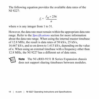
The following equation provides the available data rates of the NI 9227:
fs =
where n is any integer from 1 to 31.
However, the data rate must remain within the appropriate data rate range. Refer to the Specifications section for more information about the data rate range. When using the internal master timebase of 12.8 MHz, the result is data rates of 50 kS/s, 25 kS/s, 16.667 kS/s, and so on down to 1.613 kS/s, depending on the value of n. When using an external timebase with a frequency other than 12.8 MHz, the NI 9227 has a different set of data rates.
Note The NI cRIO-9151 R Series Expansion chassis does not support sharing timebases between modules.
fM 256÷n---------------------
NI 9227 Operating Instructions and Specifications | © National Instruments | 15
Sleep ModeThis module supports a low-power sleep mode. Support for sleep mode at the system level depends on the chassis that the module is plugged into. Refer to the chassis manual for information about support for sleep mode. If the chassis supports sleep mode, refer to the software help for information about enabling sleep mode. Visit ni.com/info and enter cseriesdoc for information about C Series documentation.
Typically, when a system is in sleep mode, you cannot communicate with the modules. In sleep mode, the system consumes minimal power and may dissipate less heat than it does in normal mode. Refer to the Specifications section for more information about power consumption and thermal dissipation.

16 | ni.com | NI 9227 Operating Instructions and Specifications
SpecificationsThe following specifications are typical for the range -40 to 70 °Cunless otherwise noted. All voltages are relative to the AI- signal on each channel unless otherwise noted.
Caution The input terminals of this device are not protected for electromagnetic interference. As a result, this device may experience reduced measurement accuracy or other temporary performance degradation when connected cables are routed in an environment with radiated or conducted radio frequency electromagnetic interference. To limit radiated emissions and to ensure that this device functions within specifications in its operational electromagnetic environment, take precautions when designing, selecting, and installing measurement probes and cables.
NI 9227 Operating Instructions and Specifications | © National Instruments | 17
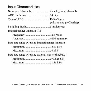
Input CharacteristicsNumber of channels.......................... 4 analog input channels
ADC resolution................................. 24 bits
Type of ADC.....................................Delta-Sigma(with analog prefiltering)
Sampling mode .................................Simultaneous
Internal master timebase (fM)
Frequency ................................... 12.8 MHzAccuracy..................................... ±100 ppm max
Data rate range (fs) using internal master timebase
Minimum.................................... 1.613 kS/sMaximum ................................... 50 kS/s
Data rate range (fs) using external master timebase
Minimum.................................... 390.625 S/sMaximum ................................... 51.36 kS/s

18 | ni.com | NI 9227 Operating Instructions and Specifications
Data rates1 (fs) ................................... , n = 1, 2, ..., 31
Safe operating input range2, 3............ 5 Arms
Overcurrent handling4....................... 10 Arms for 1 s maxwith 19 s minimumcool down time at 5 Arms
Instantaneous measuring range5
Minimum.................................... 14.051 A peakTypical ........................................ 14.977 A peak, at 23 ±5 °C
Typical scaling coefficient ................ 1.785397 μA/LSB
Input coupling...................................DC
1 The data rate must remain within the appropriate data rate range. Refer to the Understanding NI 9227 Data Rates section for more information.
2 Refer to the Safety Guidelines section for more information about safe operating voltages.
3 The maximum recommended continuous RMS current value applied simultaneously on all 4 channels to keep the power dissipation inside the module within safe operating limits.
4 Overcurrent conditions to keep the module operating within specified limits.5 The maximum DC current that produces a non-saturated reading.
fM 256÷n---------------------
NI 9227 Operating Instructions and Specifications | © National Instruments | 19
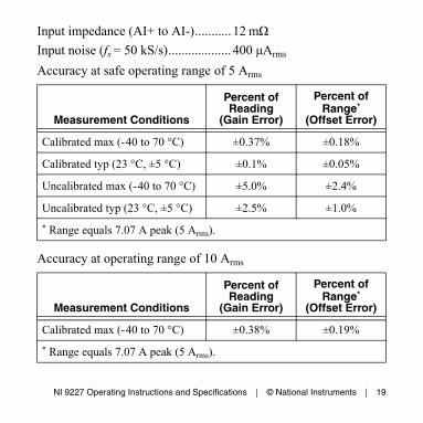
Input impedance (AI+ to AI-)........... 12 mΩ
Input noise (fs = 50 kS/s)................... 400 μArms
Accuracy at safe operating range of 5 Arms
Accuracy at operating range of 10 Arms
Measurement Conditions
Percent of Reading
(Gain Error)
Percent of Range*
(Offset Error)
Calibrated max (-40 to 70 °C) ±0.37% ±0.18%
Calibrated typ (23 °C, ±5 °C) ±0.1% ±0.05%
Uncalibrated max (-40 to 70 °C) ±5.0% ±2.4%
Uncalibrated typ (23 °C, ±5 °C) ±2.5% ±1.0%
* Range equals 7.07 A peak (5 Arms).
Measurement Conditions
Percent of Reading
(Gain Error)
Percent of Range*
(Offset Error)
Calibrated max (-40 to 70 °C) ±0.38% ±0.19%
* Range equals 7.07 A peak (5 Arms).

20 | ni.com | NI 9227 Operating Instructions and Specifications
StabilityGain drift .................................... ±21 ppm/°COffset drift .................................. ±51 μA/°C
Post calibration gain match(channel-to-channel, fin = 20 kHz)....±130 mdB max
Crosstalk(fin = 1 kHz) ................................ -90 dB
(fin = 50 Hz) ................................ -115 dB
Phase matchChannel-to-channel, max ........... 0.1°/kHzModule-to-module, max............. 0.1°/kHz + 360° · fin/fM
Phase linearity (fs = 50 kS/s) ............. 0.1° max
Input delay ........................................ 40 /fs + 2.9 μs
PassbandFrequency ................................... 0.453 · fsFlatness (fs = 50 kS/s) ................. ±100 mdB max
5512---------

NI 9227 Operating Instructions and Specifications | © National Instruments | 21
StopbandFrequency ................................... 0.547 · fsRejection..................................... 100 dB
Alias-free bandwidth ........................ 0.453 · fs-3 dB bandwidth (fs = 50 kS/s).......... 24.609 kHz
CMRR ( fin = 50 Hz).......................... 150 dB
SFDR (fin = 1 kHz, -60 dBFS).......... 110 dB
Total Harmonic Distortion (THD)(fin = 1 kHz, -1 dBFS)....................... -95 dB
MTBF ...............................................Contact NI for Bellcore MTBF or MIL-HDBK-217F specifications.
Power RequirementsPower consumption from chassis
Active mode ............................... 730 mW maxSleep mode ................................. 50 μW max
22 | ni.com | NI 9227 Operating Instructions and Specifications
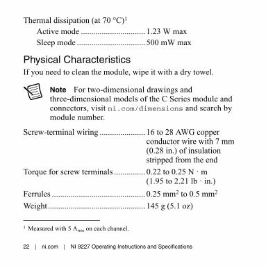
Thermal dissipation (at 70 °C)1
Active mode ............................... 1.23 W maxSleep mode ................................. 500 mW max
Physical CharacteristicsIf you need to clean the module, wipe it with a dry towel.
Note For two-dimensional drawings and three-dimensional models of the C Series module and connectors, visit ni.com/dimensions and search by module number.
Screw-terminal wiring ...................... 16 to 28 AWG copper conductor wire with 7 mm (0.28 in.) of insulation stripped from the end
Torque for screw terminals ............... 0.22 to 0.25 N · m (1.95 to 2.21 lb · in.)
Ferrules ............................................. 0.25 mm2 to 0.5 mm2
Weight............................................... 145 g (5.1 oz)
1 Measured with 5 Arms on each channel.

NI 9227 Operating Instructions and Specifications | © National Instruments | 23
SafetyIsolation VoltagesConnect only voltages that are within the following limits.
Channel-to-channelContinuous ................................. 250 Vrms,
Measurement Category IIWithstand.................................... 1,390 Vrms, verified by a 5 s
dielectric withstand test
Channel-to-earth groundContinuous ................................. 250 Vrms,
Measurement Category IIWithstand.................................... 2,300 Vrms, verified by a 5 s
dielectric withstand test
Measurement Category II is for measurements performed on circuits directly connected to the electrical distribution system. This category refers to local-level electrical distribution, such as that provided by a standard wall outlet, for example, 115 V for U.S. or 230 V for Europe.
Caution Do not connect to signals or use for measurements within Measurement Categories III or IV.
24 | ni.com | NI 9227 Operating Instructions and Specifications
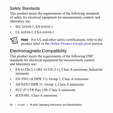
Safety StandardsThis product meets the requirements of the following standards of safety for electrical equipment for measurement, control, and laboratory use:
• IEC 61010-1, EN 61010-1
• UL 61010-1, CSA 61010-1
Note For UL and other safety certifications, refer to the product label or the Online Product Certification section.
Electromagnetic CompatibilityThis product meets the requirements of the following EMC standards for electrical equipment for measurement, control, and laboratory use:
• EN 61326-2-1 (IEC 61326-2-1): Class A emissions; Industrial immunity
• EN 55011 (CISPR 11): Group 1, Class A emissions
• AS/NZS CISPR 11: Group 1, Class A emissions
• FCC 47 CFR Part 15B: Class A emissions
• ICES-001: Class A emissions

NI 9227 Operating Instructions and Specifications | © National Instruments | 25
Note For the standards applied to assess the EMC of this product, refer to the Online Product Certification section.
Note For EMC compliance, operate this device with shielded cables.
CE ComplianceThis product meets the essential requirements of applicable European Directives as follows:
• 2006/95/EC; Low-Voltage Directive (safety)
• 2004/108/EC; Electromagnetic Compatibility Directive (EMC)
Online Product CertificationRefer to the product Declaration of Conformity (DoC) for additional regulatory compliance information. To obtain product certifications and the DoC for this product, visit ni.com/certification, search by module number or product line, and click the appropriate link in the Certification column.

26 | ni.com | NI 9227 Operating Instructions and Specifications
Shock and VibrationTo meet these specifications, you must panel mount the system and either affix ferrules to the ends of the terminal wires or use the NI 9971 backshell kit to protect the connections.
Operating vibrationRandom (IEC 60068-2-64)......... 5 grms, 10 to 500 Hz
Sinusoidal (IEC 60068-2-6) ....... 5 g, 10 to 500 Hz
Operating shock (IEC 60068-2-27)....30 g, 11 ms half sine,50 g, 3 ms half sine,18 shocks at 6 orientations
EnvironmentalNational Instruments C Series modules are intended for indoor use only but may be used outdoors if installed in a suitable enclosure. Refer to the manual for the chassis you are using for more information about meeting these specifications.
Operating temperature(IEC 60068-2-1, IEC 60068-2-2) ..... -40 to 70 °C
Storage temperature(IEC 60068-2-1, IEC 60068-2-2) ..... -40 to 85 °C
Ingress protection.............................. IP 40

NI 9227 Operating Instructions and Specifications | © National Instruments | 27
Operating humidity (IEC 60068-2-56).............................. 10 to 90% RH,
noncondensing
Storage humidity(IEC 60068-2-56).............................. 5 to 95% RH,
noncondensing
Maximum altitude............................. 2,000 m
Pollution Degree ............................... 2
Environmental ManagementNI is committed to designing and manufacturing products in an environmentally responsible manner. NI recognizes that eliminating certain hazardous substances from our products is beneficial to the environment and to NI customers.
For additional environmental information, refer to the Minimize Our Environmental Impact web page at ni.com/environment. This page contains the environmental regulations and directives with which NI complies, as well as other environmental information not included in this document.

28 | ni.com | NI 9227 Operating Instructions and Specifications
Waste Electrical and Electronic Equipment (WEEE)EU Customers At the end of the product life cycle, all products must be sent to a WEEE recycling center. For more information about WEEE recycling centers, National Instruments WEEE initiatives, and compliance with WEEE Directive 2002/96/EC on Waste and Electronic Equipment, visit ni.com/environment/weee.
CalibrationYou can obtain the calibration certificate and information about calibration services for the NI 9227 at ni.com/calibration.
Calibration interval ........................... 1 year
RoHSNational Instruments
(RoHS)National Instruments RoHSni.com/environment/rohs_china (For information about China RoHS compliance, go to ni.com/environment/rohs_china.)

NI 9227 Operating Instructions and Specifications | © National Instruments | 29
Worldwide Support and ServicesThe National Instruments website is your complete resource for technical support. At ni.com/support you have access to everything from troubleshooting and application development self-help resources to email and phone assistance from NI Application Engineers.
Visit ni.com/services for NI Factory Installation Services, repairs, extended warranty, and other services.
Visit ni.com/register to register your National Instruments product. Product registration facilitates technical support and ensures that you receive important information updates from NI.
A Declaration of Conformity (DoC) is our claim of compliance with the Council of the European Communities using the manufacturer’s declaration of conformity. This system affords the user protection for electromagnetic compatibility (EMC) and product safety. You can obtain the DoC for your product by visiting ni.com/certification. If your product supports calibration, you can obtain the calibration certificate for your product at ni.com/calibration.

30 | ni.com | NI 9227 Operating Instructions and Specifications
National Instruments corporate headquarters is located at 11500 North Mopac Expressway, Austin, Texas, 78759-3504. National Instruments also has offices located around the world. For telephone support in the United States, create your service request at ni.com/support or dial 1 866 ASK MYNI (275 6964). For telephone support outside the United States, visit the Worldwide Offices section of ni.com/niglobal to access the branch office websites, which provide up-to-date contact information, support phone numbers, email addresses, and current events.

© 2008–2014 National Instruments. All rights reserved.
375101E-01 Jul14
Refer to the NI Trademarks and Logo Guidelines at ni.com/trademarks for more information on National Instruments trademarks. Other product and company names mentioned herein are trademarks or trade names of their respective companies. For patents covering National Instruments products/technology, refer to the appropriate location: Help»Patents in your software, the patents.txt file on your media, or the National Instruments Patent Notice at ni.com/patents. You can find information about end-user license agreements (EULAs) and third-party legal notices in the readme file for your NI product. Refer to the Export Compliance Information at ni.com/legal/export-compliance for the National Instruments global trade compliance policy and how to obtain relevant HTS codes, ECCNs, and other import/export data. NI MAKES NO EXPRESS OR IMPLIED WARRANTIES AS TO THE ACCURACY OF THE INFORMATION CONTAINED HEREIN AND SHALL NOT BE LIABLE FOR ANY ERRORS. U.S. Government Customers: The data contained in this manual was developed at private expense and is subject to the applicable limited rights and restricted data rights as set forth in FAR 52.227-14, DFAR 252.227-7014, and DFAR 252.227-7015.