hornby 42/52xx 2-8-0t em finescale conversion. 42 and 52xx conversion...hornby 42/52xx 2-8-0t em...
TRANSCRIPT
Hornby 42/52xx 2-8-0T EM Finescale Conversion.
Before you start, it is a good idea to have some small containers or snap top poly bags to put screws and
components in for safe keeping......much better than crawling about on the floor trying to find lost bits!
A few cautionary notes.
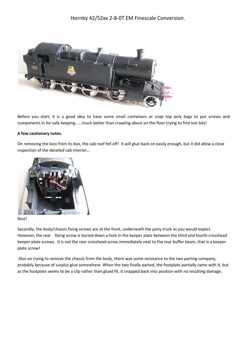
On removing the loco from its box, the cab roof fell off! It will glue back on easily enough, but it did allow a close
inspection of the detailed cab interior...
Nice!
Secondly, the body/chassis fixing screws are at the front, underneath the pony truck as you would expect.
However, the rear fixing screw is buried down a hole in the keeper plate between the third and fourth crosshead
keeper plate screws. It is not the rear crosshead screw immediately next to the rear buffer beam, that is a keeper
plate screw!
Also on trying to remove the chassis from the body, there was some resistance to the two parting company,
probably because of surplus glue somewhere. When the two finally parted, the footplate partially came with it, but
as the footplate seems to be a clip rather than glued fit, it snapped back into position with no resulting damage.

Footplate came away with chassis.
Footplate sprang back and clipped in place with no damage.
LOCO CONVERSION
1. Slacken retaining screws and remove the coupling and connecting rods. Take good note which way round the rods
fit, as they will go back on the wrong side quite easily, but will destroy the quartering and not run. Don’t ask how I
found this out, or how much time it wasted!
Also it is worth sliding out the connecting rod and crossheads from the slide bars, otherwise they will keep falling
out and be a nuisance.
Inverted chassis with rods removed.
2. Invert loco and place in a suitable cradle or similar.
3. Undo the front keeper plate screw, and slacken the second. This allows the pony truck to eased out from under the
front of the keeper plate.
4. Undo the remaining 3 cross head screws in the keeper plate - store these safely – and gently tease the keeper
plate upwards from the front end. On our sample, the keeper plate refused to part company at the rear end. A
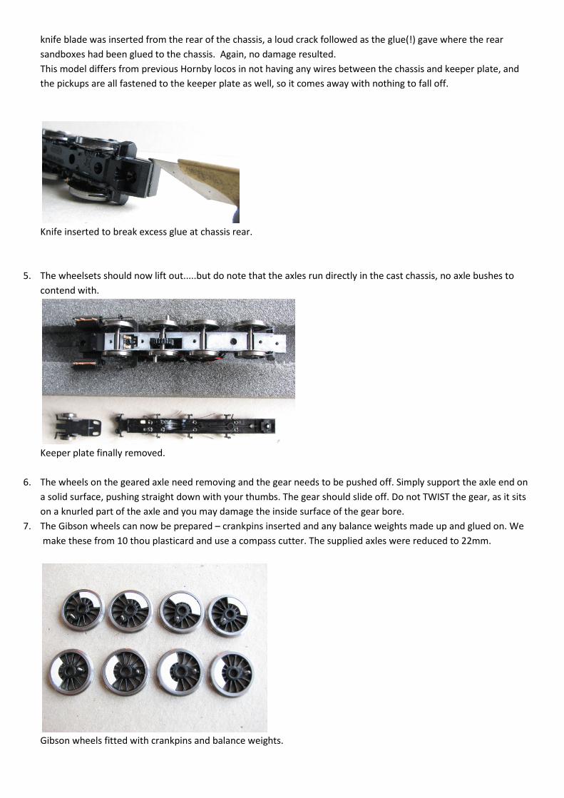
knife blade was inserted from the rear of the chassis, a loud crack followed as the glue(!) gave where the rear
sandboxes had been glued to the chassis. Again, no damage resulted.
This model differs from previous Hornby locos in not having any wires between the chassis and keeper plate, and
the pickups are all fastened to the keeper plate as well, so it comes away with nothing to fall off.
Knife inserted to break excess glue at chassis rear.
5. The wheelsets should now lift out.....but do note that the axles run directly in the cast chassis, no axle bushes to
contend with.
Keeper plate finally removed.
6. The wheels on the geared axle need removing and the gear needs to be pushed off. Simply support the axle end on
a solid surface, pushing straight down with your thumbs. The gear should slide off. Do not TWIST the gear, as it sits
on a knurled part of the axle and you may damage the inside surface of the gear bore.
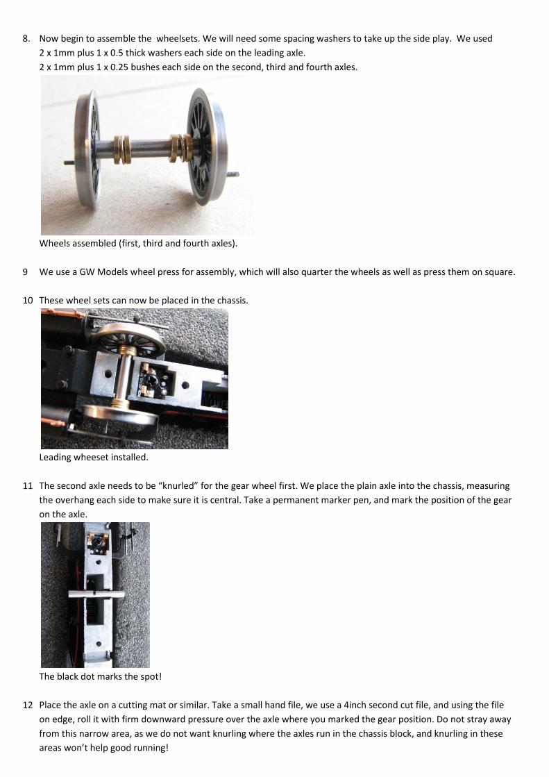
7. The Gibson wheels can now be prepared – crankpins inserted and any balance weights made up and glued on. We
make these from 10 thou plasticard and use a compass cutter. The supplied axles were reduced to 22mm.
Gibson wheels fitted with crankpins and balance weights.
8. Now begin to assemble the wheelsets. We will need some spacing washers to take up the side play. We used
2 x 1mm plus 1 x 0.5 thick washers each side on the leading axle.
2 x 1mm plus 1 x 0.25 bushes each side on the second, third and fourth axles.
Wheels assembled (first, third and fourth axles).
9 We use a GW Models wheel press for assembly, which will also quarter the wheels as well as press them on square.
10 These wheel sets can now be placed in the chassis.
Leading wheeset installed.
11 The second axle needs to be “knurled” for the gear wheel first. We place the plain axle into the chassis, measuring
the overhang each side to make sure it is central. Take a permanent marker pen, and mark the position of the gear
on the axle.
The black dot marks the spot!
12 Place the axle on a cutting mat or similar. Take a small hand file, we use a 4inch second cut file, and using the file
on edge, roll it with firm downward pressure over the axle where you marked the gear position. Do not stray away
from this narrow area, as we do not want knurling where the axles run in the chassis block, and knurling in these
areas won’t help good running!
Not too neat....but it works!
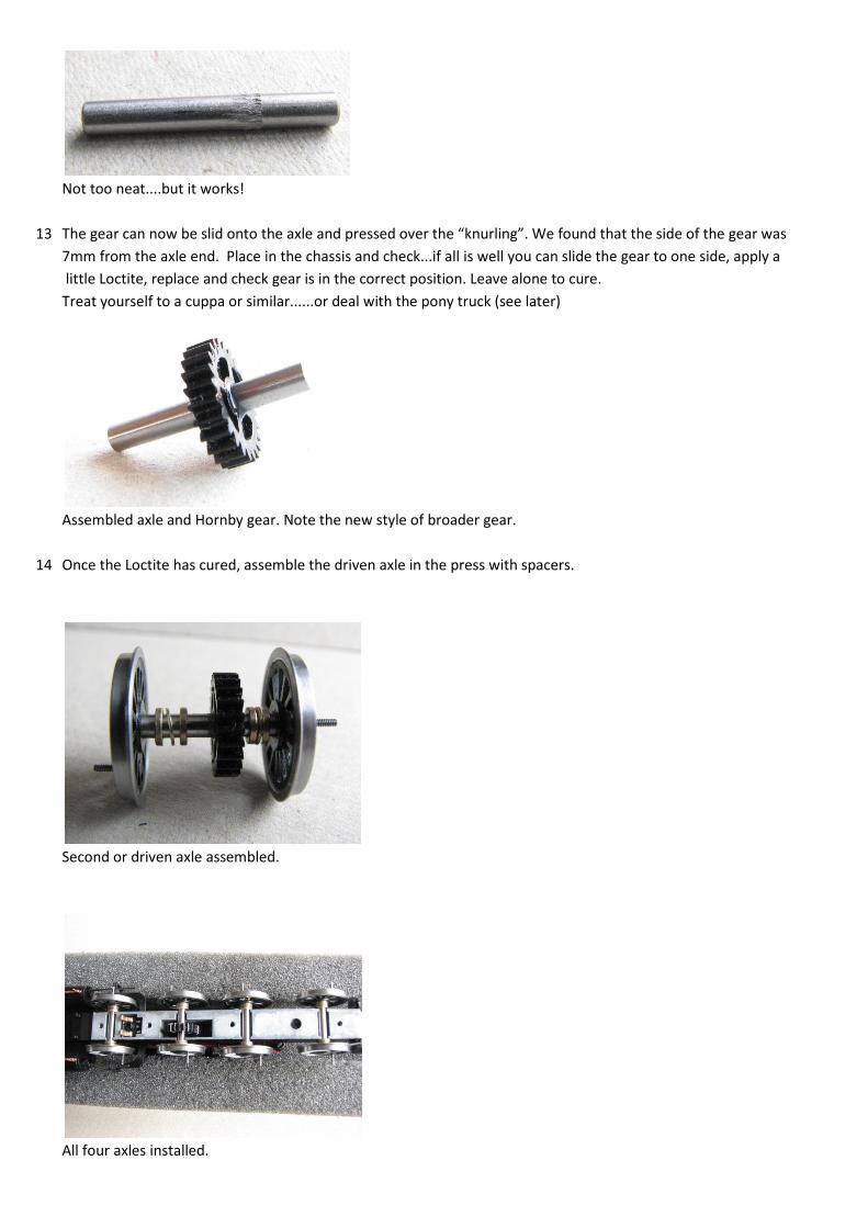
13 The gear can now be slid onto the axle and pressed over the “knurling”. We found that the side of the gear was
7mm from the axle end. Place in the chassis and check...if all is well you can slide the gear to one side, apply a
little Loctite, replace and check gear is in the correct position. Leave alone to cure.
Treat yourself to a cuppa or similar......or deal with the pony truck (see later)
Assembled axle and Hornby gear. Note the new style of broader gear.
14 Once the Loctite has cured, assemble the driven axle in the press with spacers.
Second or driven axle assembled.
All four axles installed.

15 Before we replace the keeper plate, chamfer the rear of the brake shoes with a needle file to make sure the brakes
Do not foul the wheels.
16 Lift the keeper plate back into position, trying not to damage the two delicate contacts behind the leading axle.
Ours went back without problem, and it is a good idea to just bend the pickups out a little further to accommodate
the wider gauge.
Take care with these pick up contacts, one of ours was bent double on dismantling.
17 Next we tackle the coupling rods and the connecting rod big ends. The Hornby holes are too large for Gibson
crankpins, so we need to bush them with the Gibson bushes available just for this purpose.
First, file the plating back to the brass base metal on the rear of the rods. Place a bush in the rod hole, and solder in
position. Do this for all 8 coupling rod holes, and do the connecting rods by laying the chassis on its side, working
on the rear of the rod which is face down on the work surface.
If you fill the bush completely with solder......don’t panic! As the solder sets, it contracts slightly, leaving a dimple in
the centre – use this to as your centre for drilling out. A suitable drill twiddled with fingers in a pin vice is all that is
needed.
Bush in rod ready for soldering.
The resulting central dimple after over enthusiastic soldering.

18 The bushes then need a gentle opening out to be a good running fit on the crankpin bushes....simply use a suitable
cutting broach and use one of the Gibson bushes as a guide.
19 Assemble the rods onto the wheels. Make sure you get them the correct way round and on the correct side. It is
very easy with this loco to get it wrong. How do I know......? Use a long crankpin bush on the second wheelset, and
short ones front and rear 2 axles.
Fasten with crankpin nuts front, third and rear only. Tighten and trim back the front axles crankpins, and file the
nuts to about half their thickness, in order to give clearance for the connecting rod. The rear pins can be left
for now if you wish.
Note the correct way round of the rods
20 The connecting rods need bushing and cleaning up in the same way as the coupling rods.
21 The combined crosshead and rod can now be fitted back into their respective slidebars.
22 It is a good idea to fit a spacing washer between the coupling and connecting rod, we used one of the rod spacing
bushes for this purpose, but any small washer would be fine.
Brass washer to fit between coupling and connecting rod.
23 Slip the washer over the crankpin bush, followed by the connecting rod, and finally fasten with a crankpin nut.
Completed rod assembly.

24. You can now gently track test the completed chassis.
THE PONY TRUCK
1. Simply twist and pull one Hornby wheel from its axle, and slide the remaining wheel and axle out the other side.
2. Assemble the Gibson wheel onto its axle, and then slide the appropriate spacing washers on, thread through the
pony casting hole, adding the appropriate spacing washers and remaining wheel. We used 2 x 1mm 2mm bore
brass spacing washers each side.
Re wheeling the Pony Truck.
3. Refit Pony back under the front edge of the keeper plate so its slots engage with the pegs.
Finally a bit of lubrication on all these new parts would not go amiss.
FINAL ASSEMBLY
When re fitting the chassis to the body, make sure the wires running to the rear of the motor do not become
trapped, or pull in any way. We found that the wires could snag at the motor rear, pulling along the chassis side,
towards the chassis front where the DCC socket bracket is. This bracket is rather flimsy to say the least, and was
being pulled backwards into contact with the motor flywheel, thereby acting as a very effective brake!
Pete Hill April 2013.
Other Parts Used in this Method
4800 Coupling rod Bushes
4M42 Crank pins
4M67/2 2mm Spacing Washers
4M67/3 2mm Spacing Washers
Loctite, Pete uses some of his precious stock of 601 and we wouldn’t want to comment on the suitability of
other products.