hornby 08 diesel shunter em finescale conversion. 08 diesel shunter.pdf · hornby 08 diesel shunter...
TRANSCRIPT
Hornby 08 Diesel Shunter EM Finescale Conversion.
Before you start, it is a good idea to have some small containers or snap top poly bags to put screws
and components in for safe keeping......much better than crawling about on the floor trying to find
lost bits!
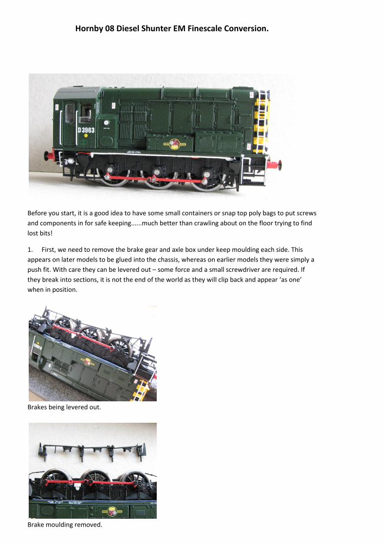
1. First, we need to remove the brake gear and axle box under keep moulding each side. This
appears on later models to be glued into the chassis, whereas on earlier models they were simply a
push fit. With care they can be levered out – some force and a small screwdriver are required. If
they break into sections, it is not the end of the world as they will clip back and appear ‘as one’
when in position.
Brakes being levered out.
Brake moulding removed.

2. Next the coupling rods can be removed by undoing the crankpin screws with fine nose pliers.
Take care, as these rods are quite delicate and can bend alarmingly if you are not careful.
Rods removed.
Store the rods safely until later. The crankpin screws can go into the spares box, as we have no
further use for them.
3. Next, we must remove the body. Undo the four screws, one in each corner underneath the
footplate, and the body lifts of easily.
Body removed.
4. The next operations are aimed at loosening the wires from the motor to the pickups to allow
them to easily to pull through the chassis from underneath later.
5. First, undo and remove the two motor mounting screws each side by the flywheel, and store
safely.
Remove the two screws, one each side by the flywheel.
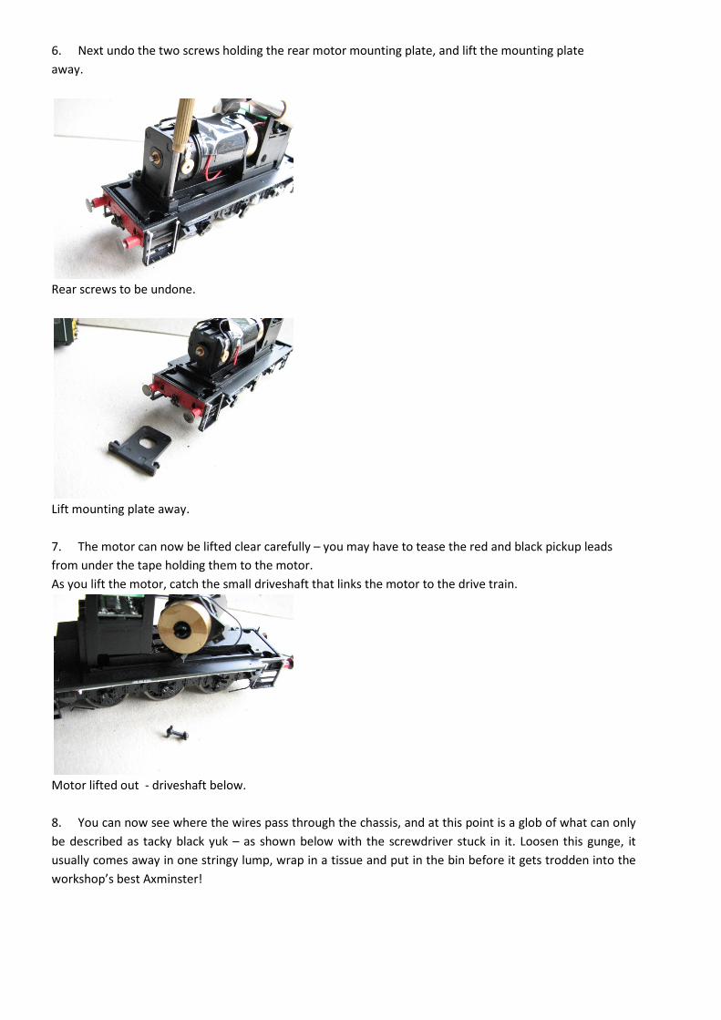
6. Next undo the two screws holding the rear motor mounting plate, and lift the mounting plate
away.
Rear screws to be undone.
Lift mounting plate away.
7. The motor can now be lifted clear carefully – you may have to tease the red and black pickup leads
from under the tape holding them to the motor.
As you lift the motor, catch the small driveshaft that links the motor to the drive train.
Motor lifted out - driveshaft below.
8. You can now see where the wires pass through the chassis, and at this point is a glob of what can only
be described as tacky black yuk – as shown below with the screwdriver stuck in it. Loosen this gunge, it
usually comes away in one stringy lump, wrap in a tissue and put in the bin before it gets trodden into the
workshop’s best Axminster!

Black sticky gunge that needs removing.
9. Once the wires will move freely through the hole in the chassis, you can carefully replace the motor,
making sure the driveshaft is fully engaged, and fasten the rear mounting plate and front mounting screws
back. It is worth checking by revolving the flywheel that the driveshaft is correctly engaged and that the
rear driven axle revolves.......very easy to not have the driveshaft engaged correctly.
10. Replace the body – it makes holding the loco in a cradle much easier for the next steps.
11. Invert the loco and hold in a suitable cradle, we use the foam Peco service cradle.
12. Undo the three screws and remove the keeper plate, which just lifts away.
Keeper plate removed.
13. The front and rear wheelsets will now lift out.
Front and rear wheelsets removed.
14. The centre wheels cannot be lifted out until the pickups are removed first. They are fastened, very
lightly, to two plastic ‘U’ shaped carriers which are in turn linked to each other by very thin clear plastic
film. The copper strips fall off this film, and will lift away with great care so as not to bend or damage them.

If you successfully removed all the black gunge from under the motor, these pick up strips should lift away
and the wires pull through without resistance.
Pickups lifting away.
Pickup carriers removed, allowing centre wheel removal.
15. We can now turn our attention to building up the wheelsets.
16. First, recover the brass bushes and drive gear from the Hornby wheels. Press the gear off the rear axle
by pushing or tapping the axle through the gear. DO NOT TWIST the gear off the axle, as it is held on
knurled splines which will damage the gear bore if twisted.
17. Mount one Gibson wheel onto the axle, and twist on until there is approx 5mm of plain axle
protruding from the front face of the wheel. We simply do this with fingers and press down on a solid
surface.
18. For the front and centre axles, place 2 x 1mm thick spacing washers onto the axle, then the two
Hornby bushes (flanges facing each other towards the centre), a further 2 x 1mm thick spacing washers,
followed by the second wheel, and set the back to back with a suitable gauge. There should be equal
amounts of axle protruding each side.
Front wheelset. Note spacing washers and Hornby bearings.
19. These two axles can now be placed in the chassis.
20. The pickups can now be eased carefully back into position. We used some insulting tape to help hold
the copper strips in position until we can put the keeper plate back on.
Front and centre wheelsets and pickups replaced.
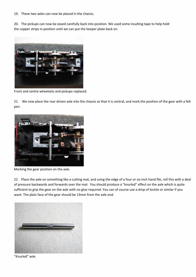
21. We now place the rear driven axle into the chassis so that it is central, and mark the position of the gear with a felt
pen.
Marking the gear position on the axle.
22. Place the axle on something like a cutting mat, and using the edge of a four or six inch hand file, roll this with a deal
of pressure backwards and forwards over the mat. You should produce a “knurled” effect on the axle which is quite
sufficient to grip the gear on the axle with no glue required. You can of course use a drop of loctite or similar if you
want. The plain face of the gear should be 13mm from the axle end.
”Knurled” axle.

Axle with gear attached.
23. The axle can now have the wheels, 2 x 1mm spacing washers and Hornby bushes placed on each side, again setting
the back to back.
24. This axle can be placed in the chassis – make sure it engages with the drive train as it is possible to fit it the wrong
way round. Don’t ask how I know.....
Rear driven axle assembled.
Rear axle in position.
25. Refit the keeper plate, and it should now look like this!
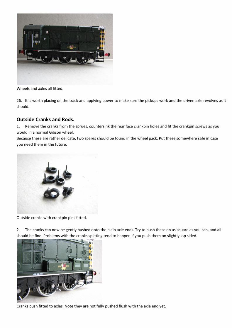
Wheels and axles all fitted.
26. It is worth placing on the track and applying power to make sure the pickups work and the driven axle revolves as it
should.
Outside Cranks and Rods.
1. Remove the cranks from the sprues, countersink the rear face crankpin holes and fit the crankpin screws as you
would in a normal Gibson wheel.
Because these are rather delicate, two spares should be found in the wheel pack. Put these somewhere safe in case
you need them in the future.
Outside cranks with crankpin pins fitted.
2. The cranks can now be gently pushed onto the plain axle ends. Try to push these on as square as you can, and all
should be fine. Problems with the cranks splitting tend to happen if you push them on slightly lop sided.
Cranks push fitted to axles. Note they are not fully pushed flush with the axle end yet.

3. We tend to push them half to three quarters onto the axle, so that quartering can be done easily.
4. Quartering is by eye I’m afraid. It does not matter if the cranks are not at 90 degrees to each other, somewhere
near is quite good enough. After all, who can see both sides at the same time, let alone measure the exact angle?
5. Once satisfied with the basic quartering, place a short crankpin bush over each pin. For a change, the rods need no
bushing to bring the holes down to size, but need a small amount of opening up with a cutting broach. Check with a
crankpin bush to get a good running fit, and carefully do all the rod holes. Again, caution. Hornby’s rods seem quite
soft and bend easily.
6. Place rods over the bushes, and retain with crankpin nuts.
7. It should be quite obvious at this point with the rods on if any further adjustment is needed to the quartering.
Rods fitted.
8. A gentle track test will confirm if the quartering is as it should be. If not, adjust and test again.
9. The final operation is to chamfer the brake blocks on the brake mouldings. These need paring or filing back to 45
degrees quite severely. Aim to remove about half the block.
Chamfer brake blocks.
10. Re fit the brake mouldings.
11. Again, track test gently to ensure nothing is catching....the sand pipes can catch you out when re fitting the brake
mouldings.
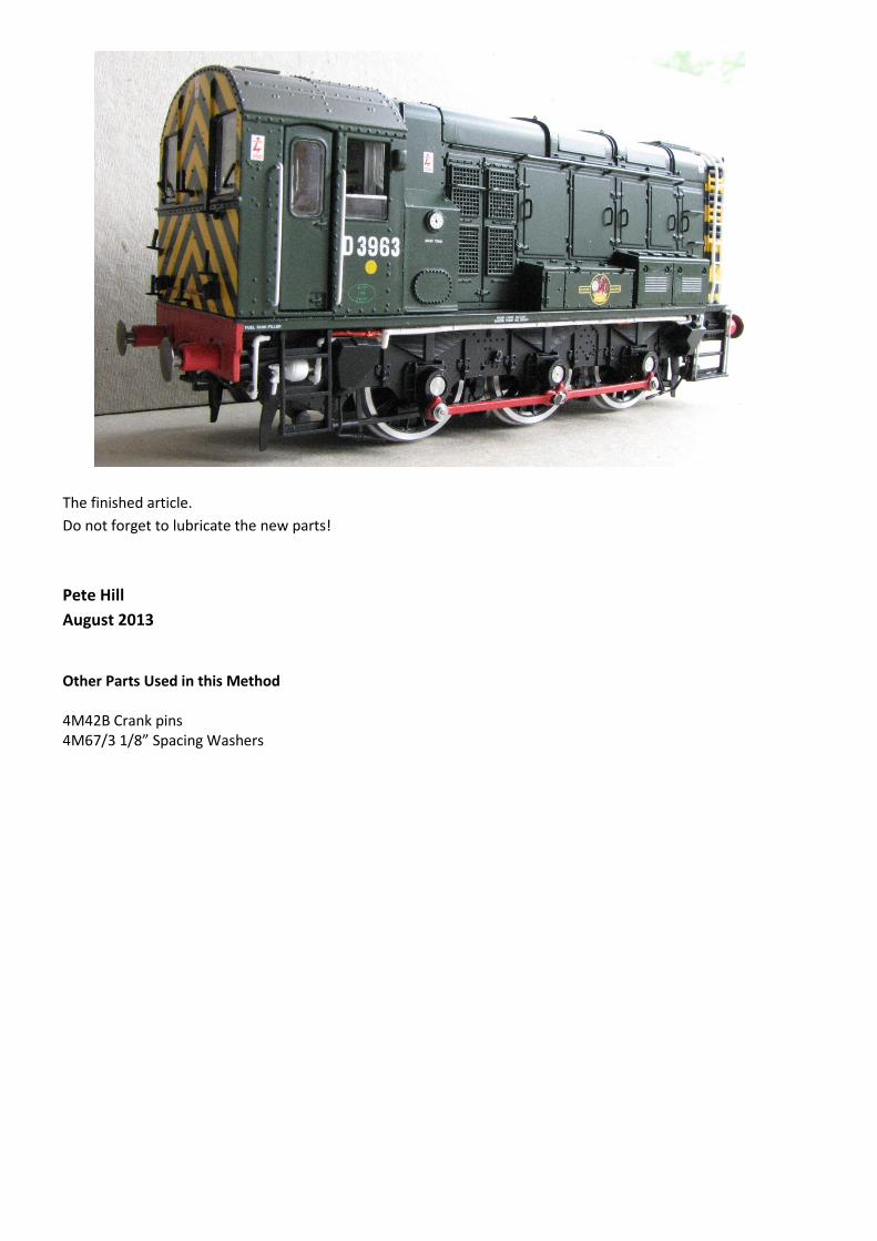
The finished article.
Do not forget to lubricate the new parts!
Pete Hill
August 2013
Other Parts Used in this Method
4M42B Crank pins
4M67/3 1/8” Spacing Washers