highway engineering unit-4
TRANSCRIPT
HIGHWAY ENGINEERING
UNIT-4
HIGHWAY CONSTRUCTION MATERIALS AND PRACTICE
Prepared By: N.Karthic AP/CIVILNPR College Of Engineering
And Technology

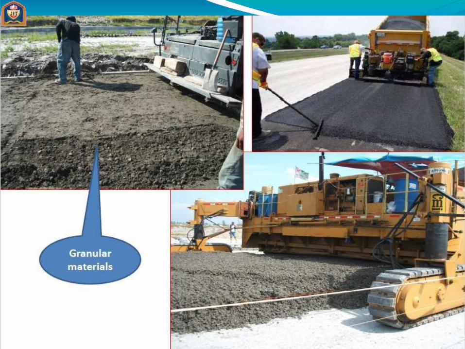
PAVEMENT pavement is the durable surface material laid down
on an area intended to sustain vehicular load or foottraffic, such as a road or walkway.
It is of twotypes
Flexible pavement or bituminous pavement or black toppavement
Rigid pavement or cement concrete pavement or whitesurface pavement

COMPARISON OF FLEXIBLE PAVEMENT & RIGID PAVEMENTFlexible Pavement Have low flexural strength Load is transferred by grainto
grain contact
Surfacing cannot be laid directlyon the sub grade but a sub base isneeded
No thermal stresses are induced expansion joints are notneeded Design life 10-15 years Initial cost of construction is low Maintenance cost is high Road can be used for trafficwithin
24 hours
Damaged by Oils and Certain Chemicals
Rigid Pavement Have more flexural strength No such phenomenon ofgrain
to grain load transferexists Surfacing can be directly laidon
the sub grade Thermal stresses are induced expansion joints are needed Design life 20-30 years Initial cost of constructionis
high Less maintenance cost Road cannot be used until 14
days of curing
No Damage by Oils andother chemicals


Requirements of a pavement Sufficient thickness to distribute thewheel load stresses to
a safe value on the sub-grade soil. Structurally strong to withstand all typesof stresses
imposed upon it.
Adequatecoefficient of friction to prevent skidding of vehicles.
Smooth surface to providecomfort to road users even athigh speed.
Produce least noise from movingvehicles.
Dust proof surface so that traffic safety is not impaired by reducing visibility.
Impervious surface, so that sub-grade soil is well protected.
Long design life with low maintenancecost.

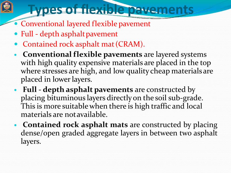
Types of flexible pavements Conventional layered flexible pavement
Full - depth asphaltpavement
Contained rock asphalt mat(CRAM).
Conventional flexible pavements are layered systems with high quality expensive materials are placed in the top where stresses are high, and low quality cheap materials are placed in lower layers.
Full - depth asphalt pavements are constructed by placing bituminous layers directly on the soil sub-grade. This is more suitable when there is high traffic and local materials are notavailable.
Contained rock asphalt mats are constructed by placingdense/open graded aggregate layers in between two asphaltlayers.
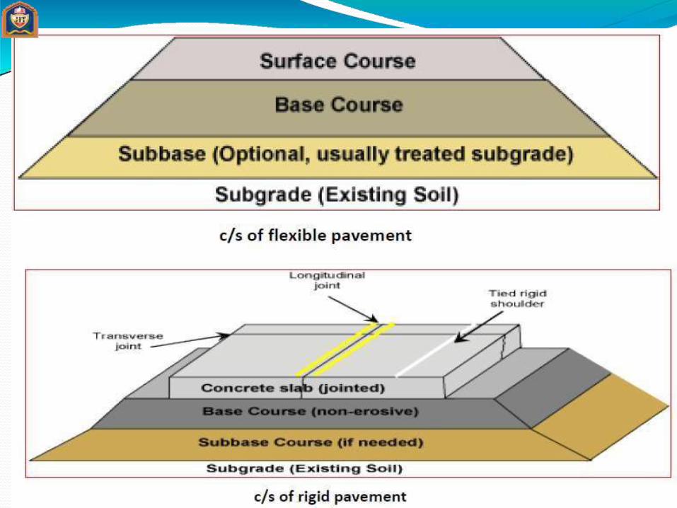

Typical layers of a flexible pavement
Surface course:
Surface course is the layer directly in contact with traffic loads and generally contains superior quality materials. They are usually constructed with dense graded asphalt concrete(AC).
It provides characteristics such as friction, smoothness, drainage, etc. Also it will prevent the entrance of excessive quantities of surface water into the underlying base, sub-base andsub-grade,
It provide a smooth and skid- resistant riding surface,
It must be water proof to protect the entire base and sub-grade from the weakening effectof water.

Binder course:
This layer provides the bulk of the asphalt concrete structure. It's chief purpose is to distribute load to the base course.
The binder course generally consists of aggregates having less asphalt and doesn't require quality as high as the surface course, so replacing a part of the surface course by the binder course results in more economical design.
Base course:
The base course is the layerof material immediately beneath the surface of binder course and it provides additional load distribution and contributes to the sub-surfacedrainage It may be composed of crushed stone and other untreated or stabilized materials.

Sub-Base course: The sub-base course is the layer of material beneath the base course and the primary functions are to provide structural support, improve drainage.
It may WBM orWMM
A sub-base course is not always needed or used. For example, a pavement constructed overa high quality.
Sub-grade: The top soil or sub-grade is a layer of natural soil prepared to receive the stresses from the layers above. It is essential that at no time soil sub-grade is overstressed.
It should be compacted to the desirable density, near the optimum moisturecontent.

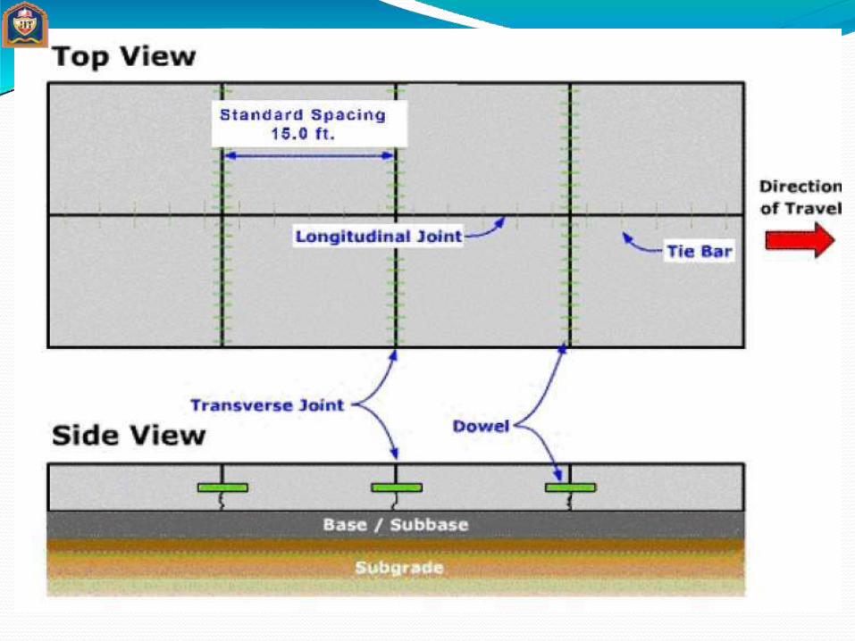
Types of Rigid Pavements Jointed plain concrete pavement (JPCP),
Jointed reinforced concrete pavement (JRCP),
Continuous reinforced concrete pavement (CRCP)
Pre-stressed concrete pavement (PCP).
Jointed Plain Concrete Pavement: constructed with closely spaced contraction joints. Dowel bars or aggregate interlocks are normally used for load transferacross joints. They normally has a joint spacing of 5 to 10m.
Jointed Reinforced Concrete Pavement: reinforcements do not improve the structural capacity significantly but they can drastically increase the joint spacing to 10 to 30m. Dowel bars are required for load transfer. Reinforcements help to keep the slab together even aftercracks.

Continuous Reinforced Concrete Pavement: Complete elimination of joints are achieved by reinforcement.


Flexible Pavement

Rigid Pavement
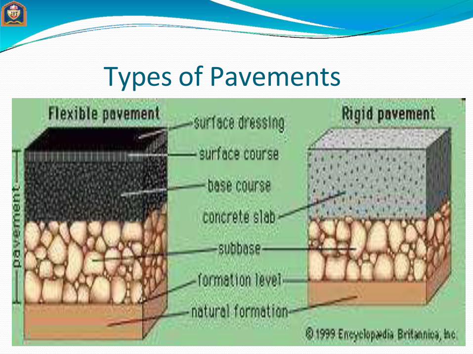
Types of Pavements


Wheel Load Distribution
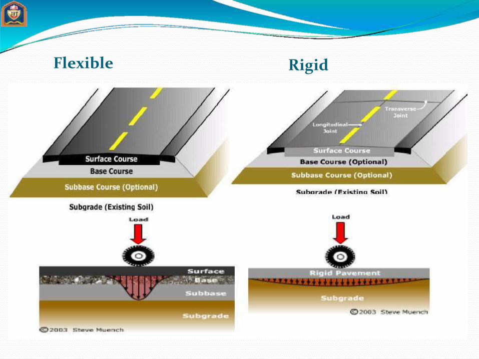
Flexible Rigid
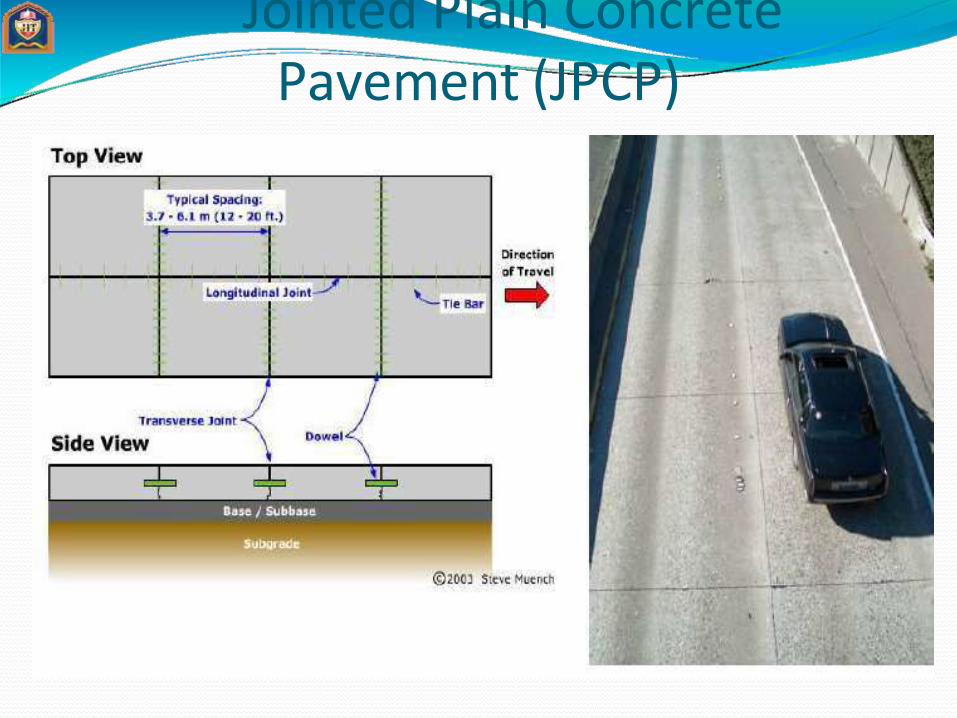
Jointed Plain Concrete Pavement (JPCP)
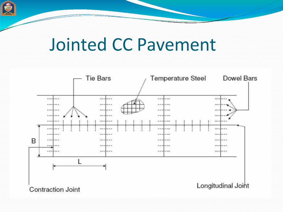
Jointed CC Pavement

Function and Significance of Subgrade Properties
Basement soil of road bed.
Important forstructural and pavement life.
Should notdeflect excessively due to dynamic loading.
May be in fill or embankment.

Flexible Pavement Design IRC (37-2001)
Basic Principles
Vertical stress or strain onsub-grade
Tensilestress or strain on surface course
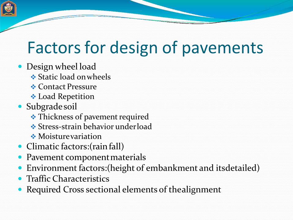
Factors for design of pavements Design wheel load
Static load onwheels Contact Pressure Load Repetition
Subgradesoil Thickness of pavement required Stress-strain behavior underload Moisturevariation
Climatic factors:(rain fall) Pavement componentmaterials Environment factors:(height of embankment and itsdetailed) Traffic Characteristics Required Cross sectional elements of thealignment

Pavement Responses Under Load
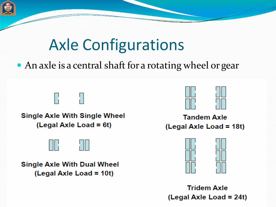
Axle Configurations An axle is a central shaft for a rotating wheel or gear
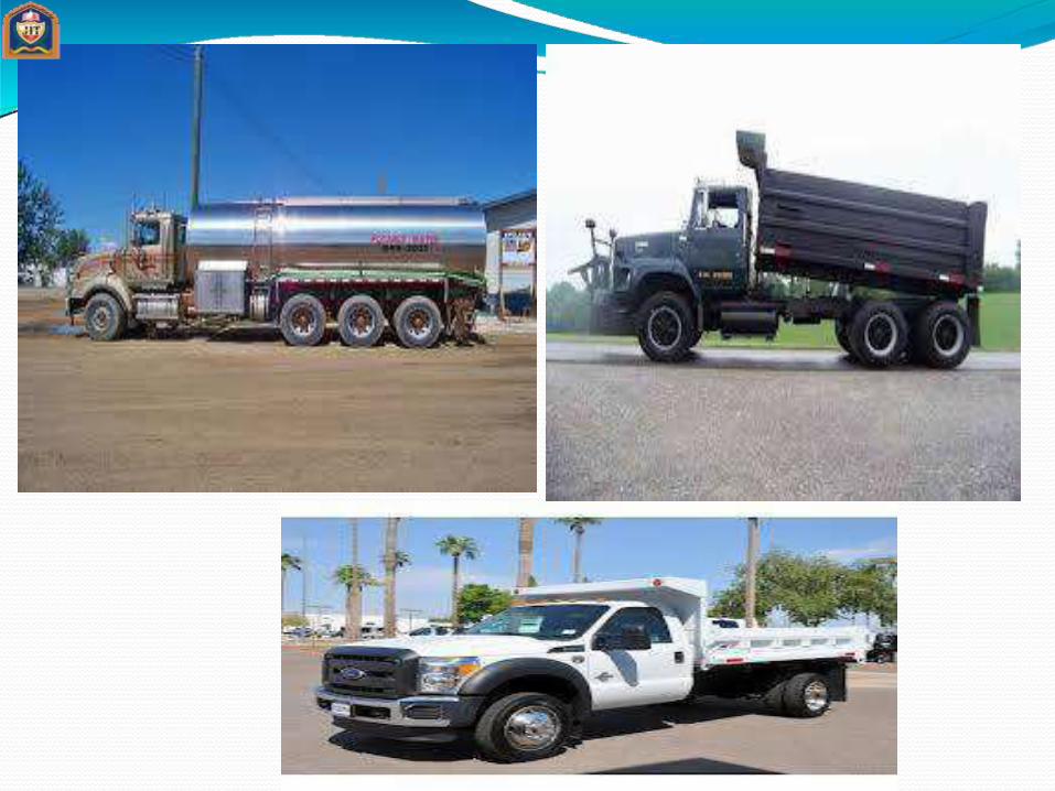

Truck Configuration

Standard Axle Single axle with dual wheels carrying a load of 80 kN
(8 tonnes) is defined as standardaxle

Evaluation Of Pavement Component Layers
Sub-grade
To Receive Layers of Pavement MaterialsPlaced over it
Plate Bearing Test
CBR Test
TriaxialCompressionTest

Flexible Pavement Design Using CBR Value Of Sub-grade Soil California State Highways Department Method
Required data
Design Traffic in termsof cumulative numberof standard axles(CSA)
CBR value of subgarde
Traffic Data
Initial data in terms of numberof commercial vehicles per day (CVPD).
Traffic growth rate during design life in %
Design life in number ofyears.
Distribution of commercial vehicles over the carriage way
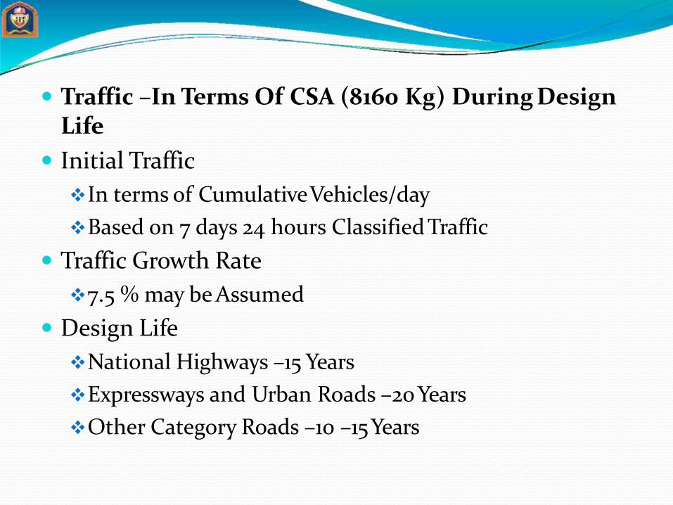
Traffic –In Terms Of CSA (8160 Kg) During Design Life
Initial Traffic
In terms of CumulativeVehicles/day
Based on 7 days 24 hours ClassifiedTraffic
Traffic Growth Rate
7.5 % may be Assumed
Design Life
National Highways –15 Years
Expressways and Urban Roads –20 Years
Other Category Roads –10 –15Years

Vehicle Damage Factor (VDF)
Multiplier to Convert No. of Commercial Vehicles ofDifferent Axle Loads and Axle Configurations to theNumber of Standard Axle Load Repetitions indicateVDF Values
Normally=(Axle Load/8.2)^n
n=4-5

INDICATIVE VDF VALUES

Distribution Of Traffic
Single Lane Roads: Total No. of Commercial Vehicles in both Directions
Two-lane Single Carriageway Roads: 75% of total No. of Commercial Vehicles in bothDirections
Four-lane Single CarriagewayRoads: 40% of the total No. of Commercial Vehicles in bothDirections
Dual Carriageway Roads: for two lane dual carriageway75% of the No. of Commercial
Vehicles in each Direction For three lane-60% For four lane-45%

Computation of Traffic for Use of Pavement Thickness Design Chart 365 x A[(1+r)n–1] N = x D x F
r N = Cumulative No. of standard axles to be catered for the design
in terms of msa D = Lane distributionfactor A = Initial traffic, in the yearof completion of construction, in
termsof numberof commercial vehicles perday =p(1-r)^X
Where,P=no. of commercial vehicle as per last countX=no. of year between the last count and the yearof completion
of constructionF = Vehicle Damage Factor n = Design life inyearsr = Annual growth rate of commercial vehicles

CBR Testing Machine Definition: It is the ratio of force per unit area
required to penetrate a soil mass with standard circular piston at the rate of 1.25 mm/min. to that required for the corresponding penetration of a standard material.
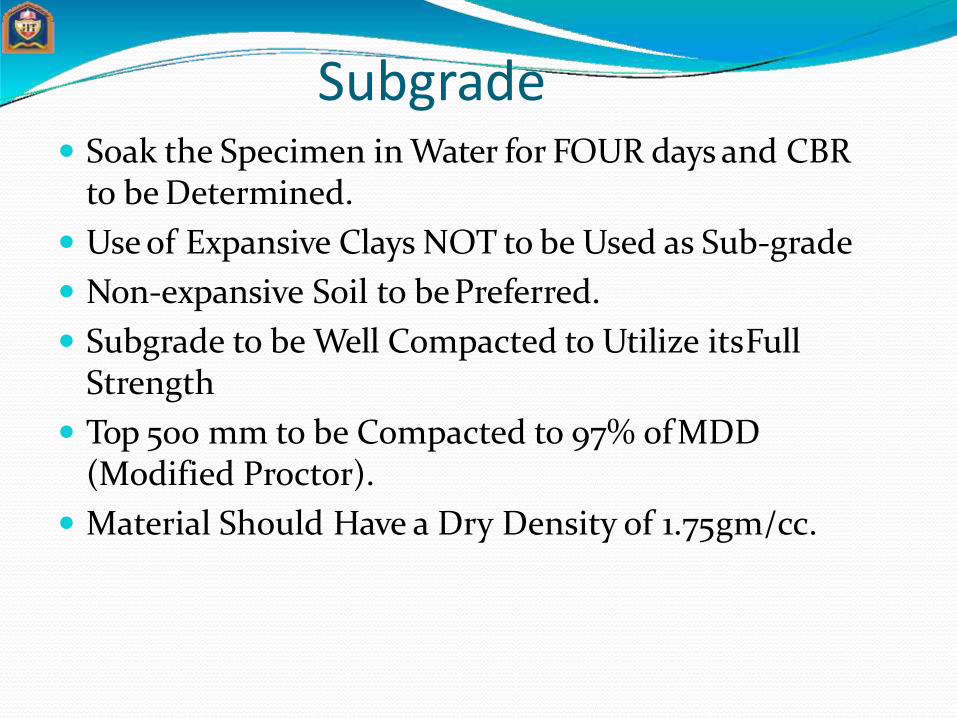
Subgrade Soak the Specimen in Water for FOUR days and CBR
to be Determined.
Use of Expansive Clays NOT to be Used as Sub-grade
Non-expansive Soil to bePreferred.
Subgrade to be Well Compacted to Utilize itsFull Strength
Top 500 mm to be Compacted to 97% of MDD (Modified Proctor).
Material Should Have a Dry Density of 1.75gm/cc.

Flexible pavement design chart (IRC) (for CSA< 10 msa)
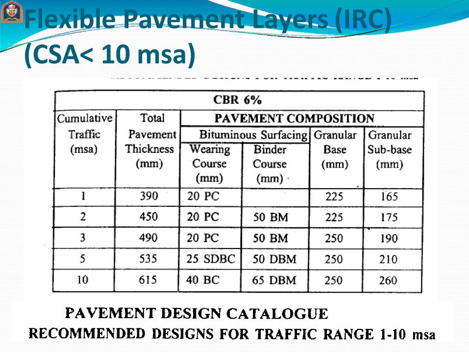
Flexible Pavement Layers (IRC) (CSA< 10 msa)
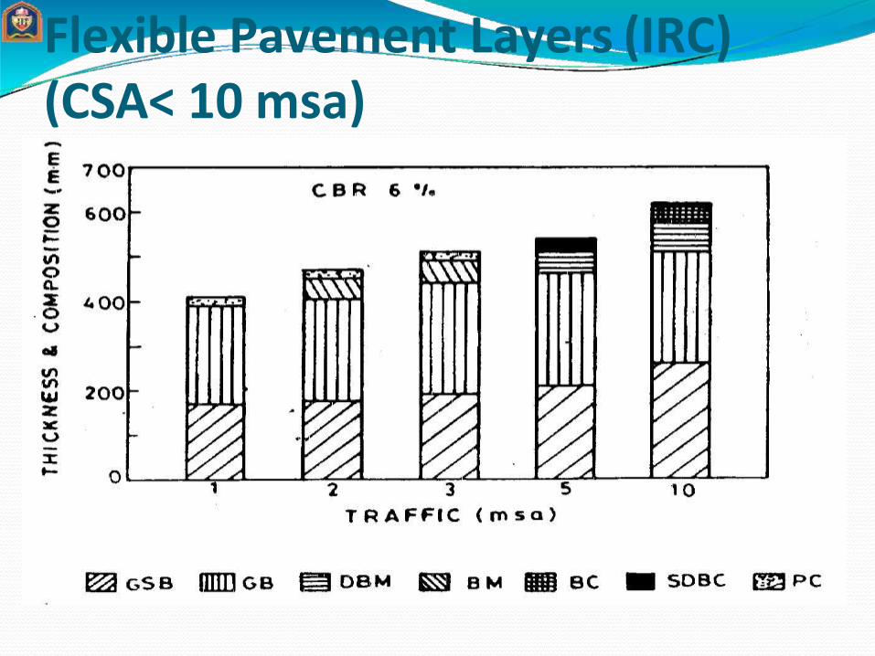
Flexible Pavement Layers (IRC) (CSA< 10 msa)

Flexible pavement design chart (IRC)
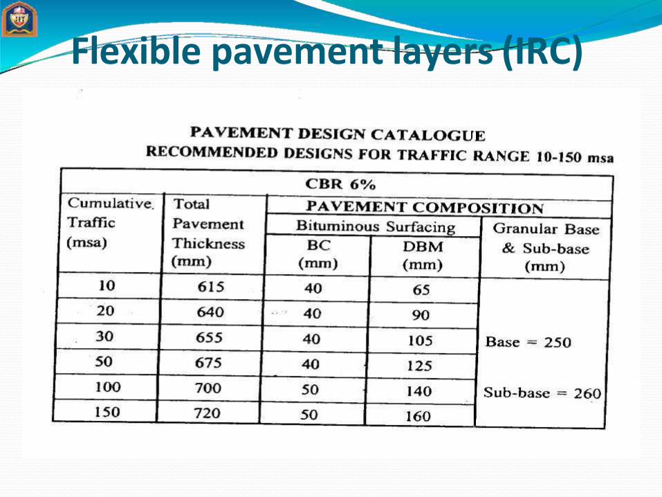
Flexible pavement layers (IRC)

Flexible pavement layers (IRC)
Sub-base Material –Natural Sand, Moorum, Gravel, Laterite, Kankar,
Brick Metal, Crushed Stone, Crushed Slag, Crushed Concrete
GSB-Close Graded / Coarse Graded
Parameters –Gradation, LL, PI, CBR
Stability and Drainage Requirements
Min. CBR 20 % -Traffic up-to 2 msa
Min. CBR 30 %-Traffic > 2 msa

If GSB is Costly, Adopt WBM, WMM
Min. Thickness –150 mm -<10 msa
Min. Thickness –200 mm ->10 msa
Min. CBR –2 %
If CBR < 2% -Pavement Thickness for 2 % CBR + Capping layerof 150 mm with Min. CBR 10% (in addition to the Sub-Base)
In case of Stage Construction –Thickness of GSB forFull Design Life

Base Course Unbound Granular Bases –WBM / WMM or any other
Granular Construction
Min. Thickness –225 mm –< 2 msa
Min. Thickness –250 mm -> 2 msa
WBM –Min. 300 mm ( 4 layers –75mmeach)

Design of rigid pavement as per IRC-58:2002Stress acting on the rigid pavement are:
Wheel load stress
Interior loading
Edge loading
Corner loading
Temperature stress
Warping stress
Frictional stress


Radius of relative stiffness
Wherel= Radius of relativestiffnessE= modulus of elasticity of cement concrete, kg/cm²μ= poisson’sratio for concrete= 0.15 h= slab thickness,cmK= modulus of subgrade reaction, kg/cm³

Westergaard’sstress equation for wheel load Stress at theinterior(si)
Stress at theedge (se)
Stress at thecorner (sc)

Where,
P= design wheel load, kg
l= Radius of relative stiffness
E= modulus of elasticity of cement concrete , kg/cm²
μ= poisson’sratio for concrete= 0.15
h= slab thickness, cm
K= modulus of subgrade reaction, kg/cm³
b= radius of equivalent distribution of pressure, cm
b=a , if a/h ≥ 1.724
b= √(1.6 a²+h²) -0.675 h, when a/h < 1.724
a= radius of load contact,cm

Modified Westergaard’s stress equation for wheel load Modified by ‘Teller’
Modified by ‘Kelley’

Warping stress(given by ‘Bradbury’) Stress at theinterior(sti)
Stress at theedge (ste)
Stress at the corner (stc)

Where,
E= modulus of elasticity of cementconcrete , kg/cm²
e= thermal coefficient of concrete perºC
t= temperature difference between the top and bottom of the slab in degreeC
μ= poisson’sratio for concrete= 0.15
Cx= Bradbury coefficient based on L/I indesire direction (IRC-58:2002)
Cy = Bradbury coefficient based on B/I in right angle to the desire direction(IRC-58:2002)
L = length of slab, m
B= width of slab, m

Frictional stress Frictional stress(sf)
Where,
sf= unit stress developed in CC pavement, kg/cm²
W= unit wt. of concrete, (about 2400kg/cm²)
L= length of slab, m
B= width of slab, m