heavy-duty hcci development activities - energy.gov · heavy duty hcci development activities kevin...
TRANSCRIPT

Heavy Duty HCCI Development Activities
Kevin Duffy, Andy Kieser, Mike Liechty, Tony Rodman, Bill Hardy, Carl Hergart
Charles Schleyer, Rafal Sobotowski
DOE Contract DE-FC05-00OR22806Team Leader: Gurpreet Singh Prog. Mgr.: Roland GravelTech. Mgr.: Carl Maronde
DOE DEER ConferenceChicago, IL
August 21-25, 2005

Agenda
• Background• Systems approach• Controls Development• Heat Flux Measurements• Optical Engine Results• HCCI fuel effects• Conclusions

Engine Industry Challenges
• Improving fuel efficiency while meeting much more stringent emissions standards is a tremendous technicalchallenge.
2003
NOx(g/hphr)0 0.5 1.0 1.5 2.0 2.5 3.0
2003
Thermal Efficiency
NOx(g/hphr)0 0.5 1.0 1.5 2.0 2.5 3.0
20072010
45
50
55
2003
NOx(g/hphr)0 0.5 1.0 1.5 2.0 2.5 3.0
2003
Thermal Efficiency
NOx(g/hphr)0 0.5 1.0 1.5 2.0 2.5 3.0
20072010
45
50
55
Technology Investment

Fuel Systems
In-cylinder Diagnostics
Air Systems
FEA
Systems Approach to HCCI Development
Single and Multi Cylinder Testing
Aftertreatment
HCCI Fuels
Aftertreatment
CombustionDevelopment
Controls
Simulation
Injection
Timing
Boost
Pressure
VGT Position
Back
Pressure
VIVA Setting
Compression
Ratio
A/F Ratio
Efficiency
EmissionsCylinder
Pressure
Rise Rate
Desired
Speed/
Power
Exhaust
Temperature
Heat Rejection
Percent CGI
Pressure
Ratio
CGI Valve
A/F Ratio
Efficiency
Emissions
Desired
Speed/
Power
Injection
Timing
Boost
Pressure
VGT Position
Back
Pressure
VIVA Setting
Compression
Ratio
A/F Ratio
Efficiency
EmissionsCylinder
Pressure
Rise Rate
Desired
Speed/
Power
Exhaust
Temperature
Heat Rejection
Percent CGI
Pressure
Ratio
CGI Valve
A/F Ratio
Efficiency
Emissions
Desired
Speed/
Power

Controls Challenges
• Need robust method for detecting start of combustion (cylinder pressure sensor, ion sensor, torque fluctuation on crank, knock sensor, strain gauged head bolts, microphones, etc.)
• Transient operation, transitioning to different speed/load points
• Activities:– Sensor evaluation– RPAC installation, feedback control capability on multi– Preliminary controls architecture developed– Cylinder pressure feedback implemented– Basic phasing control demonstrated using intake valve
actuation (IVA) to balance cylinders– Speed and load step tests demonstrated

VVA for Cylinder Balancing
Feedback off Feedback on

300 RPM Transition, Constant Load
Baseline transition strategy Optimized transition strategy

Fuel Systems
In-cylinder Diagnostics
Air Systems
FEA
Systems Approach to HCCI Development
Single and Multi Cylinder Testing
Aftertreatment
HCCI Fuels
Aftertreatment
CombustionDevelopment
Controls
Simulation
Injection
Timing
Boost
Pressure
VGT Position
Back
Pressure
VIVA Setting
Compression
Ratio
A/F Ratio
Efficiency
EmissionsCylinder
Pressure
Rise Rate
Desired
Speed/
Power
Exhaust
Temperature
Heat Rejection
Percent CGI
Pressure
Ratio
CGI Valve
A/F Ratio
Efficiency
Emissions
Desired
Speed/
Power
Injection
Timing
Boost
Pressure
VGT Position
Back
Pressure
VIVA Setting
Compression
Ratio
A/F Ratio
Efficiency
EmissionsCylinder
Pressure
Rise Rate
Desired
Speed/
Power
Exhaust
Temperature
Heat Rejection
Percent CGI
Pressure
Ratio
CGI Valve
A/F Ratio
Efficiency
Emissions
Desired
Speed/
Power
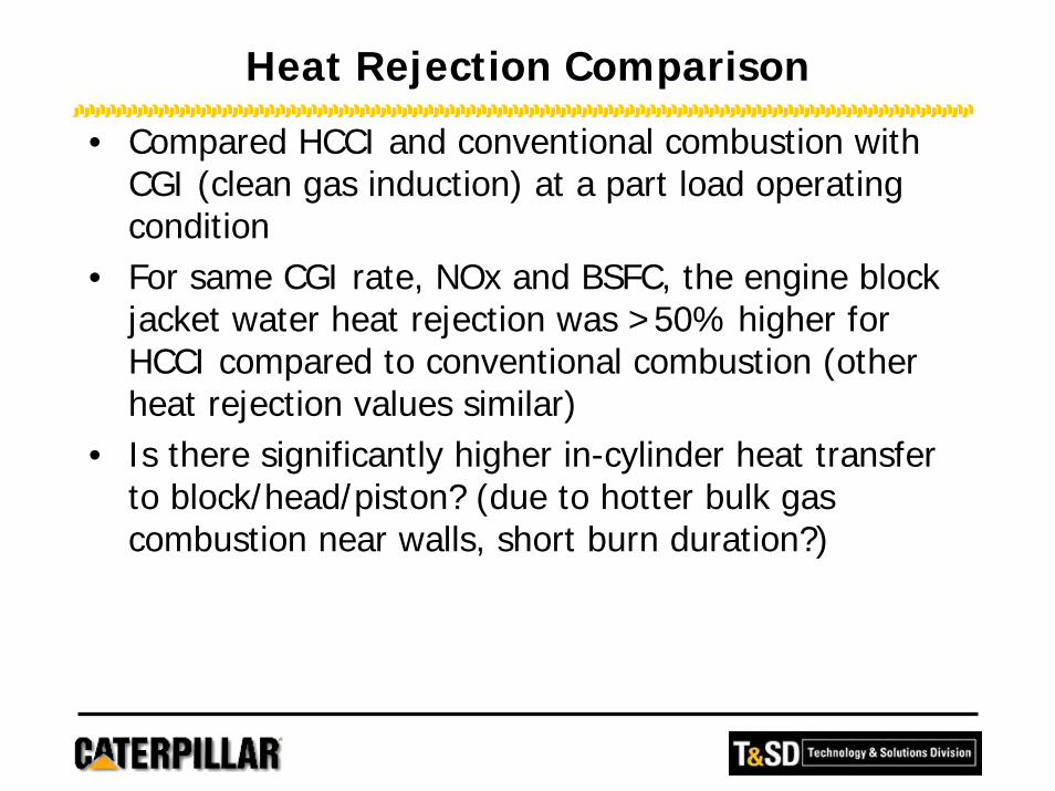
Heat Rejection Comparison
• Compared HCCI and conventional combustion with CGI (clean gas induction) at a part load operating condition
• For same CGI rate, NOx and BSFC, the engine block jacket water heat rejection was >50% higher for HCCI compared to conventional combustion (other heat rejection values similar)
• Is there significantly higher in-cylinder heat transfer to block/head/piston? (due to hotter bulk gas combustion near walls, short burn duration?)

Related Research
• Tsurushima et al. premixed DME/Propane HCCI (SAE 2002-01-0108)
• Chang et al. gasoline HCCI (SAE 2004-01-2996)

• Medtherm-heat flux probe– Two j-type TC, front side and back side– Front side has micro-second response time– Installed in head between exhaust valves
• Instrumented liner– 20 k-type TC radially– ~ 15 mm from liner top– Results showed no major
difference in liner tempsbetween HCCI and conventional combustion
Heat Flux Measurement

Knock Effect on Heat Flux
HCCI operation, 1500 rpm
0
2
4
6
8
10
12
14
-30 -20 -10 0 10 20 30 40 50 60
Crank Angle Degree
cylin
der p
ress
ure
(MP
a)
0
1
2
3
4
5
6
7
8
9
10
Hea
t Flu
x (M
W/m
2)
1900 BMEP, baseline CGI%
1860 BMEP, baseline - 5% CGI1500 BMEP, baseline - 11% CGI

Heat flux vs combustion phasing
1
2
3
4
5
6
7
8
9
10
11
-15 -10 -5 0 5 10 15 20
start of combustion (deg atdc)
Hea
t Flu
x (M
W/m
^2)
1800 rpm, >1400 BMEP1800 rpm, 1000 BMEP1500 rpm, 1500 BMEP1500 rpm, 1000 BMEP1200 rpm, >1500 BMEP1200 rpm, 1000 BMEPConventional Comb, 1800 rpmConventional Comb, 1500 rpmConventional Comb, 1200 rpmpremixed DME/propane HCCI
Trendline - Conventional
Trendline - HCCI
Effect of Partial Stratification

Fuel Systems
In-cylinder Diagnostics
Air Systems
FEA
Systems Approach to HCCI Development
Single and Multi Cylinder Testing
Aftertreatment
HCCI Fuels
Aftertreatment
CombustionDevelopment
Controls
Simulation
Injection
Timing
Boost
Pressure
VGT Position
Back
Pressure
VIVA Setting
Compression
Ratio
A/F Ratio
Efficiency
EmissionsCylinder
Pressure
Rise Rate
Desired
Speed/
Power
Exhaust
Temperature
Heat Rejection
Percent CGI
Pressure
Ratio
CGI Valve
A/F Ratio
Efficiency
Emissions
Desired
Speed/
Power
Injection
Timing
Boost
Pressure
VGT Position
Back
Pressure
VIVA Setting
Compression
Ratio
A/F Ratio
Efficiency
EmissionsCylinder
Pressure
Rise Rate
Desired
Speed/
Power
Exhaust
Temperature
Heat Rejection
Percent CGI
Pressure
Ratio
CGI Valve
A/F Ratio
Efficiency
Emissions
Desired
Speed/
Power

• Goal of Project: use optical diagnostic techniques to supply a knowledge base of in-cylinder processes under LTC operating conditions– To understand reasons underlying observed emissions levels– To gain insight into approaches to implement fuel or
hardware changes that ameliorate the problems– To help validate simulations of in-cylinder mixing and LTC
• Partnering with Chuck Mueller and Glen Martin at Sandia on the Caterpillar/Sandia 3171 optical engine
• Optical diagnostics techniques used include natural luminosity, liquid and vapor phase spray imaging, soot imaging, PLIF
Optical Engine Testing with Sandia National Lab

Sandia Compression-ignition Optical Research Engine (SCORE)
Research engine 1-cyl. Cat 3176Cycle 4-stroke CIDIValves per cylinder 4Bore 125 mmStroke 140 mmIntake valve open 32° BTDC exhaustIntake valve close 153° BTDC compr.Exhaust valve open 116° ATDC compr.Exhaust valve close 11° ATDC exhaustConn. rod length 225 mmConn. rod offset NonePiston bowl diameter 90 mmPiston bowl depth 16.4 mmSquish height 1.5 mmSwirl ratio 0.59Displacement per cyl. 1.72 litersFuel Injector HEUI 450AInjector tip Multi-hole nozzle

Camera View Orientation for Cycle Integrated Natural Luminosity (CINL) Movies

CINL Movie of HCCI Combustion

Fuel Systems
In-cylinder Diagnostics
Air Systems
FEA
Systems Approach to HCCI Development
Single and Multi Cylinder Testing
Aftertreatment
HCCI Fuels
Aftertreatment
CombustionDevelopment
Controls
Simulation
Injection
Timing
Boost
Pressure
VGT Position
Back
Pressure
VIVA Setting
Compression
Ratio
A/F Ratio
Efficiency
EmissionsCylinder
Pressure
Rise Rate
Desired
Speed/
Power
Exhaust
Temperature
Heat Rejection
Percent CGI
Pressure
Ratio
CGI Valve
A/F Ratio
Efficiency
Emissions
Desired
Speed/
Power
Injection
Timing
Boost
Pressure
VGT Position
Back
Pressure
VIVA Setting
Compression
Ratio
A/F Ratio
Efficiency
EmissionsCylinder
Pressure
Rise Rate
Desired
Speed/
Power
Exhaust
Temperature
Heat Rejection
Percent CGI
Pressure
Ratio
CGI Valve
A/F Ratio
Efficiency
Emissions
Desired
Speed/
Power

Fuel/Engine Systems Approach
OptimizedOptimizedSystemsSystems
Benefits For:• Consumer• Environment• Industry
CAT ExxonMobil
Hardware Fuel
Engine Testing Advanced Characterization
Systems Integration Refining Process Technology
Combustion Modeling Chemical Kinetics
Fluid Dynamics Systems Modeling
CCC• CC•C
C*CC C2C*OC•CCOOH
C*CC• C2•C*OHOOCCCHO + OH•
CCC
“A” “B” “C” “D” “E”

Preliminary Fuel Effects Study
• Study parameters:– Ignitability
• Cetane number: 39 - 55
• Octane number (R+M)/2: 63 - 91
– Aromatic content• 28 - 45%
– Volatility• Gasoline
• No.1 diesel fuel
• No.2 diesel fuel
• Other fuel parameters generally well matched when varying single property
Cetane Number 39 >>> Cetane
Number 46
Aromatics % 43 Aromatics
% 45
T90, oF 625 T90, oF 615
DIESEL FUELS
Cetane Number 47 Cetane
Number 47 >>> Cetane Number 55
Aromatics % 28 Aromatics
% 28 Aromatics % 28
T90, oF 495 >>> T90, oF 596 T90, oF 618
GASOLINES
(R+M)/2 63 >>> (R+M)/2 81 >>> (R+M)/2 91Aromatics
% 15 Aromatics % 26 Aromatics
% 27
T90, oF 315 T90, oF 309 T90, oF 299A
rom
atic
s >>
>

Test Engine
• Single-cylinder Caterpillar 3401 engine• Cylinder displacement: 2.44 liters• Bore/Stroke: 137/165 mm• Valves/cylinder: 4• Swirl ratio: 0.4 • Hydraulically intensified fuel injection
system. Multi-hole nozzle• All emissions engine-out• Main control variables: fuel injection
timing, boost/backpressure• Careful engine control to identify fuel
effects

No Benefit for Increased Cetane in Expanding High Load Operability
• Increasing cetane # produced undesirable advance in combustion phasing
• Cylinder pressure rise rate and increase in peak cylinder pressure result in lower load capability
• Similar behavior for natural and additized cetane
0
1
2
3
4
5
6
7
8
9
10
-40 -30 -20 -10 0 10 20 30 40Crank Angle, deg.
Cyl
inde
r Pr
essu
re, M
Pa
CN: 38.5CN: 45.9 (Add.)CN: 45.5
-20-15-10 -5 0 5 10 15 20 25 30Crank Angle Degree
0
5
10
Pcyl
(MPa
)
0
100
200
Hea
t Rel
ease
Rat
e (k
J/de
g)
No.2 DieselCN: 46.7
No.2 DieselCN: 55.4 1500 rpm
50% Load
1200 rpm25% Load

Cetane Number Had Small Effect on Emissions
020406080
100120
Early Injection Timing Late
NO
x, p
pm
CN = 46.7 CN = 55.4
00.010.020.030.040.05
Early Injection Timing Late
AVL
Sm
oke
Num
ber CN = 46.7 CN = 55.4
0
2000
4000
6000
8000
Early Injection Timing Late
CO
, ppm
CN = 46.7 CN = 55.4
0
10
20
30
40
Early Injection Timing LateTher
mal
Effi
cien
cy, %
CN = 46.7 CN = 55.41800 rpm, 25% load

Aromatics Has Small Impact on Emissions
020406080
100
Early Injection Timing Late
NO
x, p
pm
Aro = 44.7% Aro = 28.7%
00.020.040.060.08
0.1
Early Injection Timing Late
AV
L S
mok
e N
umbe
r Aro = 44.7% Aro = 28.7%
0500
10001500200025003000
Early Injection Timing Late
HC
, ppm
Aro = 44.7% Aro = 28.7%
02000400060008000
10000
Early Injection Timing Late
CO
, ppm
Aro = 44.7% Aro = 28.7%1500 rpm, 25% load

Increased Volatility Generally Reduces Emissions
0
2
4
6
8
10
-40 -20 0 20 40Crank Angle, deg.
Cyl
inde
r Pre
ssur
e, M
Pa
T90 = 596 F T90 = 495 F
01020304050
0 20 40 60Engine Load, %
NO
x, p
pm
T90 = 596 F T90 = 495 F
1800 rpm
1200 rpm
1200 rpm
0
0.040.08
0.12
0.16
0 20 40 60Engine Load, %
AVL
Sm
oke
Num
ber T90 = 596 F T90 = 495 F
1800 rpm
1200 rpm
1200 rpm
0
400
800
1200
0 20 40 60Engine Load, %
HC
, ppm
T90 = 596F T90 = 495 F
1800 rpm
1200 rpm
1200 rpm
1800 rpm, 25% load

Gasoline Can Also Achieve High HCCI Engine Loads
• Reduced octane rating enabled operation over a broader speed/load range
1200 rpm 1800 rpm 1200 rpm 1800 rpm 1200 rpm 1800 rpm
Maximum Load
Achieved70% 82% 75% 75%
Minimum Load
Achieved25% 25% 50% 50%
HCCI operation was only achieved
at 71%.
HCCI operation was not achieved at any engine
load
(R+M)/2 = 63.2 (R+M)/2 = 81.2 (R+M)/2 = 91.2

Numerous Challenges Remain For HCCI
• Cold start with lower compression ratios• Air system development requirements• Light load HC/CO cleanup• Controlling combustion phasing and transient
operation• Cylinder to cylinder variability• Structural reliability with higher cylinder
pressure and rise rates• Small hole production related issues• Noise/vibration
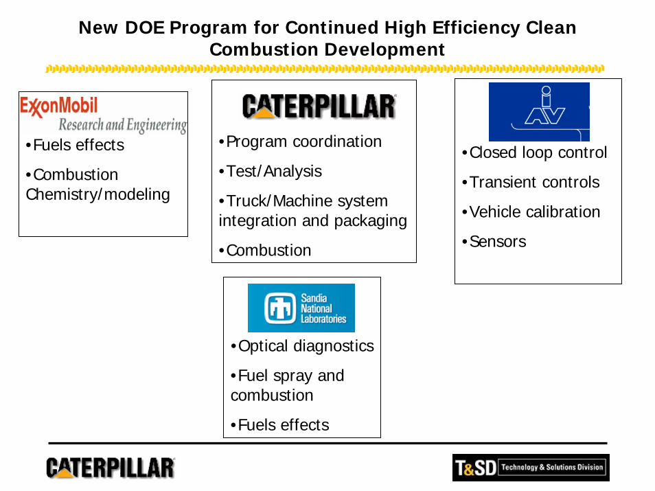
New DOE Program for Continued High Efficiency Clean Combustion Development
•Program coordination
•Test/Analysis
•Truck/Machine system integration and packaging
•Combustion
•Fuels effects
•Combustion Chemistry/modeling
•Optical diagnostics
•Fuel spray andcombustion
•Fuels effects
•Closed loop control
•Transient controls
•Vehicle calibration
•Sensors

Summary
• Significant progress made on expanding operating range for HD HCCI engine
• Full load HCCI is extremely challenging• Fuels effects can have positive/negative impacts on
performance and emissions• Much work still needed to determine production
feasibility of HCCI as a 2010 emissions strategy• Advanced technology Diesel engines should continue to
have long term viability as a prime power source for on and off-highway markets