heat transfer characteristics of ammonia-water...
TRANSCRIPT

Luo, C., et al.: Heat Transfer Characteristics of Ammonia-Water Falling Film ... THERMAL SCIENCE: Year 2017, Vol. 21, No. 3, pp. 1251-1259 1251
HEAT TRANSFER CHARACTERISTICS OF AMMONIA-WATER FALLING FILM GENERATION OUTSIDE
A VERTICAL TUBE
by
Chao LUO a,b,c*, Jun ZHAO c, and Weibin MA a,b
a Guangzhou Institute of Energy Conversion, Chinese Academy of Sciences, Guangzhou, China b Key Laboratory of Renewable Energy, Chinese Academy of Sciences, Guangzhou, China
c Key Laboratory of Efficient Utilization of Low and Medium Grade Energy, Tianjin University, Ministry of Education, Tianjin, China
Original scientific paper https://doi.org/10.2298/TSCI150515183L
A heat transfer experimental of vertical out-tube falling film was conducted with different inlet spray density of ammonia-water solution and inlet hot water tem-perature. The inlet liquid mass concentration was selected as 60% of ammonia. The experiments showed that the overall heat transfer coefficient increases with the increase of inlet spray density and a maximum overall heat transfer coefficient could be obtained in an optimum spray density of ammonia-water solution, Γ, be-tween 0.26 and 0.29 kg/ms. The generation of ammonia vapor outside the vertical falling film had a similar trend with the overall heat transfer coefficient basing on different spray density. The effect of hot water temperature difference, ΔT, on over-all heat transfer coefficient showed that ΔT between 10 and 13 K is the optimum temperature difference of the vertical falling film generation.Key words: heat transfer performance, vertical falling film, generation,
ammonia-water solution
Introduction
The use of binary and ternary mixtures as a working fluid was strongly recommended to improve the system performance not only in generation cycles but also in combined cycles. The internal heat exchange owing to the temperature glide of a binary mixture provides the fundamental basis for the generation cycle such as generator absorber heat exchange (GAX) cycle [1] and the combined cycle [2]. Ammonia-water (NH3-H2O) solution pair was widely used in generator-absorption cycles because of its excellent thermal characteristics. It is also an attractive to ozone-depleting chlorofluorocarbon (CFC) and CO2 emitting hydrofluorocarbon (HFC) used in conventional vapor compression systems. In both GAX and Kalina cycles, the generator is one of the most critical components from the viewpoint of size and performance. It has a complicated heat and mass transfer mechanism which influences the system performance significantly. To increase the heat transfer performance and design a more compact generator, a vertical out-tube falling film heat transfer was experimentally investigated in this paper. The ammonia-water solution in the film falling on the outside of the vertical tube was heated by hot water from boiler.
* Corresponding author, e-mail: [email protected]

Luo, C., et al.: Heat Transfer Characteristics of Ammonia-Water Falling Film ... 1252 THERMAL SCIENCE: Year 2017, Vol. 21, No. 3, pp. 1251-1259
Falling film heat transfer has been widely utilized in the chemical engineering. Rel-evant research has been performed in this area. However, most research previously conducted was analytical. There were comparatively few experimental investigations performed on this type of heat transfer [3]. Chun and Seban [4] conducted falling film generation heat transfer ex-periments of water on the outside surface of vertical tube and published important experimental data. So far, the experimental data have been used by many investigators to validate the theoret-ical simulations of falling film heat transfer. Kang et al. [5] studied the combined heat and mass transfer for NH3-H2O falling film absorption. In Shi’s [6] experiment with LiBr/H2O solution, for falling film evaporation inside vertical tube, the relations of local heat transfer coefficient, heat flux, and inlet concentration were correlated. The heat transfer test of water falling film in-side a vertical tube carried out by Fujita and Ueda [7] showed that increasing Reynolds number of laminar falling film flow results in an insignificant decreasing of the heat transfer coefficient. Xia et al. [8, 9] mathematically and experimentally investigated the capillary-assisted evapora-tion inside circumferential rectangular groove. In the capillary-assisted evaporation, the liquid film outside the tube was heated by the hot fluid inside the tube evaporates. Compared with the horizontal falling film for ammonia-water solution, this research demonstrates that the vertical falling film have a higher heat transfer coefficient in lower hot water temperature.
The performance of ammonia-water solution falling film generation heat transfer is seldom found in literature. In order to have an in-depth understanding of the process of the fall-ing film evaporation, a set of experiments of vertical falling film for ammonia-water solution was carried out under the conditions of spray density, Γ, between 0.15 and 0.35 kg/ms and the inlet hot water temperature, T, between 343.15 K and 358.15 K.
Experimental methods and procedures
Experimental set-up
In the vertical falling film evaporation experiments, it is essential to keep the liquid film on the tube wall stable and to have uniform film thickness. If the film distributor is not perpendicular to the horizontal level or the annular gap is partially blocked, the wall of the test tube would locally dry out because of uneven film spreading, the temperature around the dry area on the wall will be higher than the temperature around the wet area. In the experimental test the recorded parameters include the inlet and outlet volume flow rate, the inlet and outlet temperature of ammonia-water solution, the generation pressure of the ammonia-water solution in test cell, the inlet and outlet temperature of hot water and the volume flow rate of hot water.
Schematics and picture of the experimental set-up are shown in figs. 1 and 2, respec-tively. Main components and all connections and valves are made of stainless steel. Teflon is used as a seal material. The test cell of falling film generation has a total height of 5 m, and is equipped internally with heating tube. Figure 1 gives schematic diagram of the experimental set-up. The test section is composed of two basic flow loops: the generation of high concentra-tion ammonia-water solution outside the vertical falling film tube surface loop and hot water from boiler inside the vertical falling film tube loop. The generated ammonia steam is absorbed by the low concentration ammonia-water solution in the vertical falling film absorber. The heat loss of hot water transferring through the juncture of the shell to the ground and through the shell surface to the ambient may account for a considerably high percentage of the input heat. As a result, the thermal loss significantly influences the boiling heat transfer inside the generator. The shell of adiabatic material instead of metal material effectively impedes the heat loss to the ground. The polypropylene shell is thermally insulated with polytetrafluoro-

Luo, C., et al.: Heat Transfer Characteristics of Ammonia-Water Falling Film ... THERMAL SCIENCE: Year 2017, Vol. 21, No. 3, pp. 1251-1259 1253
ethylene to reduce the heat loss to the ambi-ent. The volume of the vapor-liquid separator has to be sufficiently large to ensure that the liquid droplet in the mixture of the liquid and vapor can be separated by gravity. In this ex-periment the outside tube and inside tube of the test cell has an outside diameter of ∅57 mm with 3.5 mm wall thickness and ∅25 mm with 2.0 mm wall thickness respectively. For observ-ing the state of falling film and adjusting the designed bottom position of the interface, the test cell is equipped with two Pyrex sight glass with 80 mm sight diameter.
Figure 2 gives the picture of the experi-ment, we have to observe the state of the inlet liquid for helping the ladder because the height of the actual experiment platform is 7.5 m. All of the tubes for hot water, cooling water and ammonia-water solution were insulated. Devi-ation of measurement data could not be avoided as the precision of measuring instruments.
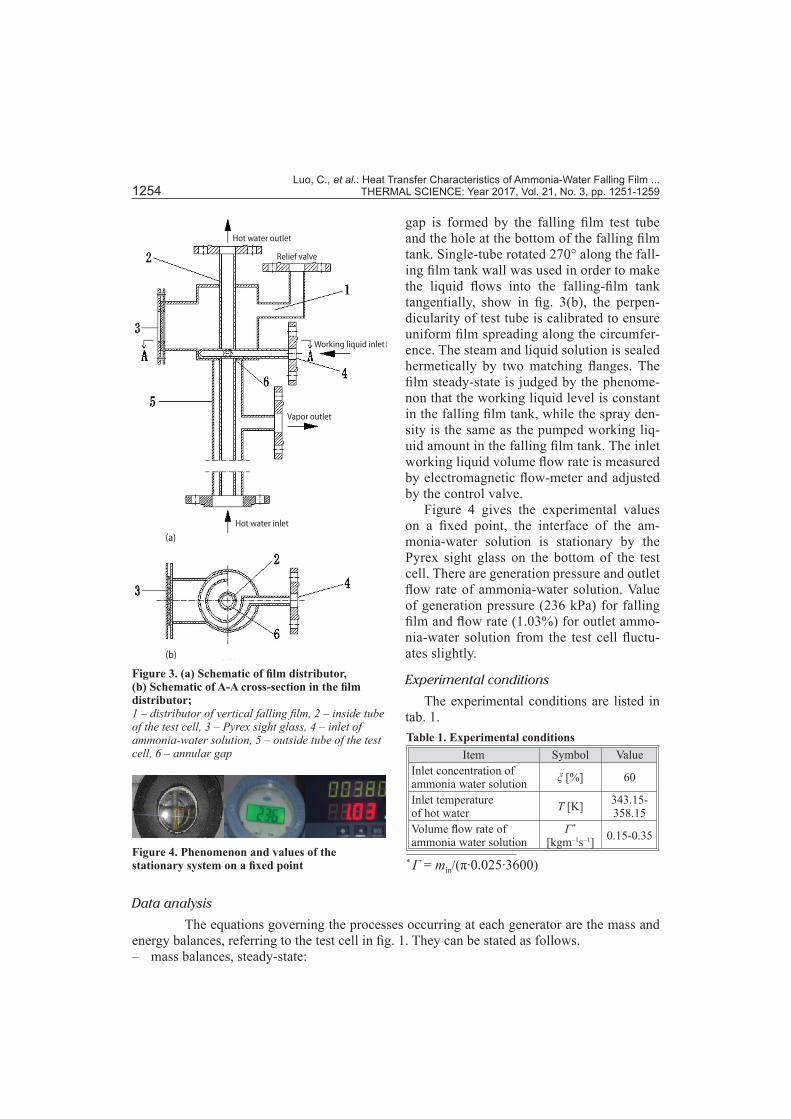
Figure 3 shows the schematic of the film distributor. The working liquid through the tan-gential inlet and annular gap flows down along the outside vertical tube surface. The annular
Figure 1. Schematic diagram of the experimental set-up;1 – test section of vertical falling film generator, 2 – Pyrex sight glass, 3 – feed hot water pump, 4 – reduce pressure valve, 5 – flow meter, 6 – heat exchanger, 7 – feed ammonia-water solution pump, 8 – vertical falling film absorber, 9 – feed ammonia-water solution tank, 10 – cooling tower, 11 – boiler. The points T and P represent thermocouple and pressure transducer, respectively
Outlet of hot water
Inlet of ammonia water solution
Outlet of ammoniavapor
Figure 2. Picture of the experimental set-up
Luo, C., et al.: Heat Transfer Characteristics of Ammonia-Water Falling Film ... 1254 THERMAL SCIENCE: Year 2017, Vol. 21, No. 3, pp. 1251-1259
gap is formed by the falling film test tube and the hole at the bottom of the falling film tank. Single-tube rotated 270° along the fall-ing film tank wall was used in order to make the liquid flows into the falling-film tank tangentially, show in fig. 3(b), the perpen-dicularity of test tube is calibrated to ensure uniform film spreading along the circumfer-ence. The steam and liquid solution is sealed hermetically by two matching flanges. The film steady-state is judged by the phenome-non that the working liquid level is constant in the falling film tank, while the spray den-sity is the same as the pumped working liq-uid amount in the falling film tank. The inlet working liquid volume flow rate is measured by electromagnetic flow-meter and adjusted by the control valve.
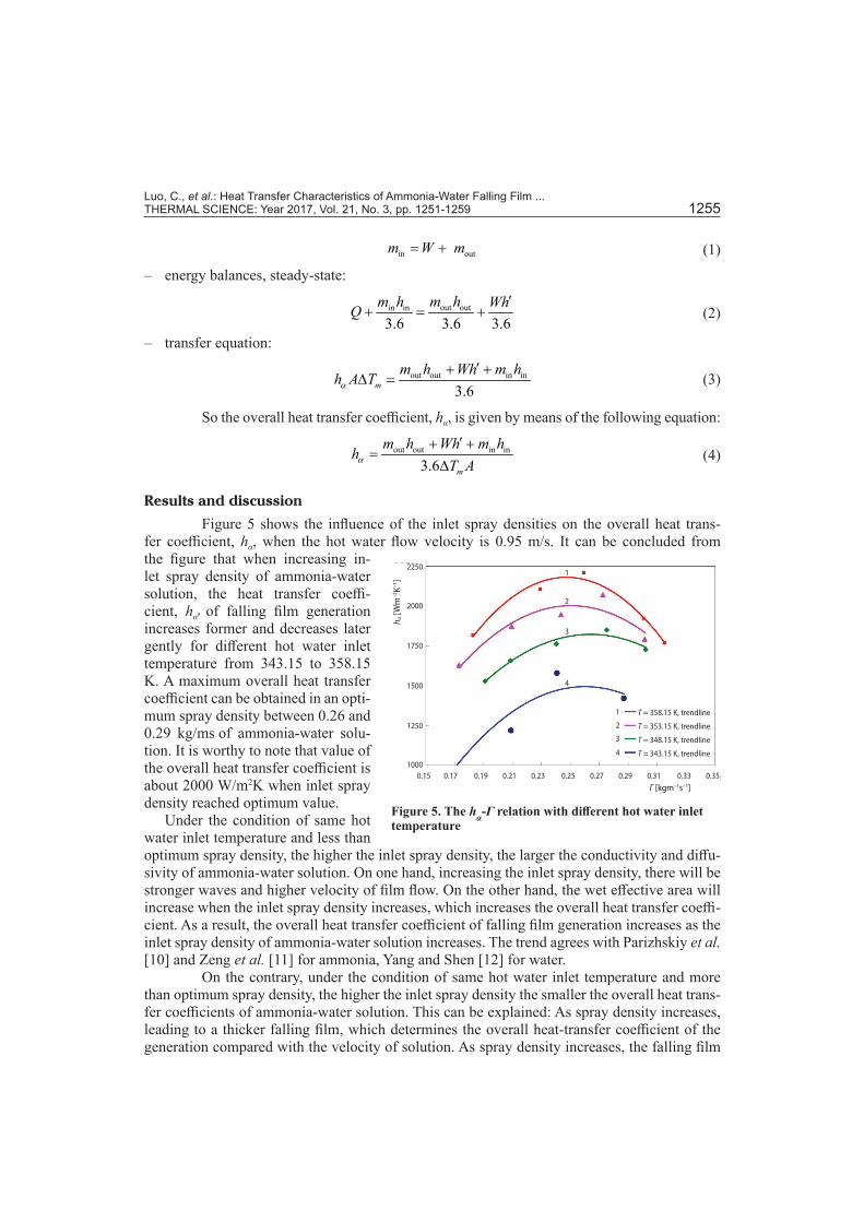
Figure 4 gives the experimental values on a fixed point, the interface of the am-monia-water solution is stationary by the Pyrex sight glass on the bottom of the test cell. There are generation pressure and outlet flow rate of ammonia-water solution. Value of generation pressure (236 kPa) for falling film and flow rate (1.03%) for outlet ammo-nia-water solution from the test cell fluctu-ates slightly.
Experimental conditions
The experimental conditions are listed in tab. 1.
Data analysis
The equations governing the processes occurring at each generator are the mass and energy balances, referring to the test cell in fig. 1. They can be stated as follows. – mass balances, steady-state:
Figure 3. (a) Schematic of film distributor, (b) Schematic of A-A cross-section in the film distributor;1 – distributor of vertical falling film, 2 – inside tube of the test cell, 3 – Pyrex sight glass, 4 – inlet of ammonia-water solution, 5 – outside tube of the test cell, 6 – annular gap
Hot water outlet
Working liquid inlet
Relief valve
Vapor outlet
Hot water inlet
(a)
(b)
Figure 4. Phenomenon and values of the stationary system on a fixed point
Table 1. Experimental conditionsItem Symbol Value
Inlet concentration of ammonia water solution ξ [%] 60
Inlet temperature of hot water T [K] 343.15-
358.15Volume flow rate of ammonia water solution
Γ * [kgm–1s–1] 0.15-0.35
* Γ = min/(π∙0.025∙3600)
Luo, C., et al.: Heat Transfer Characteristics of Ammonia-Water Falling Film ... THERMAL SCIENCE: Year 2017, Vol. 21, No. 3, pp. 1251-1259 1255
in out m W m= + (1)
– energy balances, steady-state:
out outin in
3.6 3.6 3.6m hm h WhQ
′+ = + (2)
– transfer equation:
out out in in
3.6mm h Wh m hh A Tα
′+ +∆ = (3)
So the overall heat transfer coefficient, hα, is given by means of the following equation:
out out in in
3.6 m
m h Wh m hhT Aα
+=
∆′ +
(4)
Results and discussion
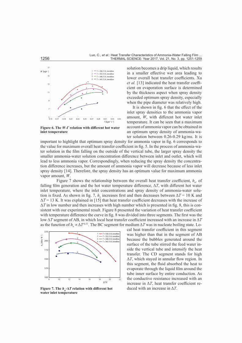
Figure 5 shows the influence of the inlet spray densities on the overall heat trans-fer coefficient, hα, when the hot water flow velocity is 0.95 m/s. It can be concluded from the figure that when increasing in-let spray density of ammonia-water solution, the heat transfer coeffi-cient, hα, of falling film generation increases former and decreases later gently for different hot water inlet temperature from 343.15 to 358.15 K. A maximum overall heat transfer coefficient can be obtained in an opti-mum spray density between 0.26 and 0.29 kg/ms of ammonia-water solu-tion. It is worthy to note that value of the overall heat transfer coefficient is about 2000 W/m2K when inlet spray density reached optimum value.
Under the condition of same hot water inlet temperature and less than optimum spray density, the higher the inlet spray density, the larger the conductivity and diffu-sivity of ammonia-water solution. On one hand, increasing the inlet spray density, there will be stronger waves and higher velocity of film flow. On the other hand, the wet effective area will increase when the inlet spray density increases, which increases the overall heat transfer coeffi-cient. As a result, the overall heat transfer coefficient of falling film generation increases as the inlet spray density of ammonia-water solution increases. The trend agrees with Parizhskiy et al. [10] and Zeng et al. [11] for ammonia, Yang and Shen [12] for water.
On the contrary, under the condition of same hot water inlet temperature and more than optimum spray density, the higher the inlet spray density the smaller the overall heat trans-fer coefficients of ammonia-water solution. This can be explained: As spray density increases, leading to a thicker falling film, which determines the overall heat-transfer coefficient of the generation compared with the velocity of solution. As spray density increases, the falling film
Figure 5. The hα-Γ relation with different hot water inlet temperature
T = 358.15 K, trendline
T = 353.15 K, trendline
T = 348.15 K, trendline
T = 343.15 K, trendline
0.15 0.17 0.19 0.21 0.23 0.25 0.27 0.29 0.31 0.33 0.35
Γ [kgm–1s–1]
2250
2000
1750
1500
1250
1000
h a [W
m–2
K–1]
1
2
3
4
1
2
3
4
Luo, C., et al.: Heat Transfer Characteristics of Ammonia-Water Falling Film ... 1256 THERMAL SCIENCE: Year 2017, Vol. 21, No. 3, pp. 1251-1259
solution becomes a drip liquid, which results in a smaller effective wet area leading to lower overall heat transfer coefficients. Xu et al. [13] indicated the heat transfer coeffi-cient on evaporation surface is determined by the thickness aspect when spray density exceeded optimum spray density, especially when the pipe diameter was relatively high.
It is shown in fig. 6 that the effect of the inlet spray densities to the ammonia vapor amount, W, with different hot water inlet temperature. It can be seen that a maximum account of ammonia vapor can be obtained in an optimum spray density of ammonia-wa-ter solution between 0.26-0.29 kg/ms. It is
important to highlight that optimum spray density for ammonia vapor in fig. 6 corresponds to the value for maximum overall heat transfer coefficient in fig. 5. In the process of ammonia-wa-ter solution in the film falling on the outside of the vertical tube, the larger spray density the smaller ammonia-water solution concentration difference between inlet and outlet, which will lead to less ammonia vapor. Correspondingly, when reducing the spray density the concentra-tion difference increases, but the amount of ammonia vapor will decrease because of less inlet spray density [14]. Therefore, the spray density has an optimum value for maximum ammonia vapor amount, W.
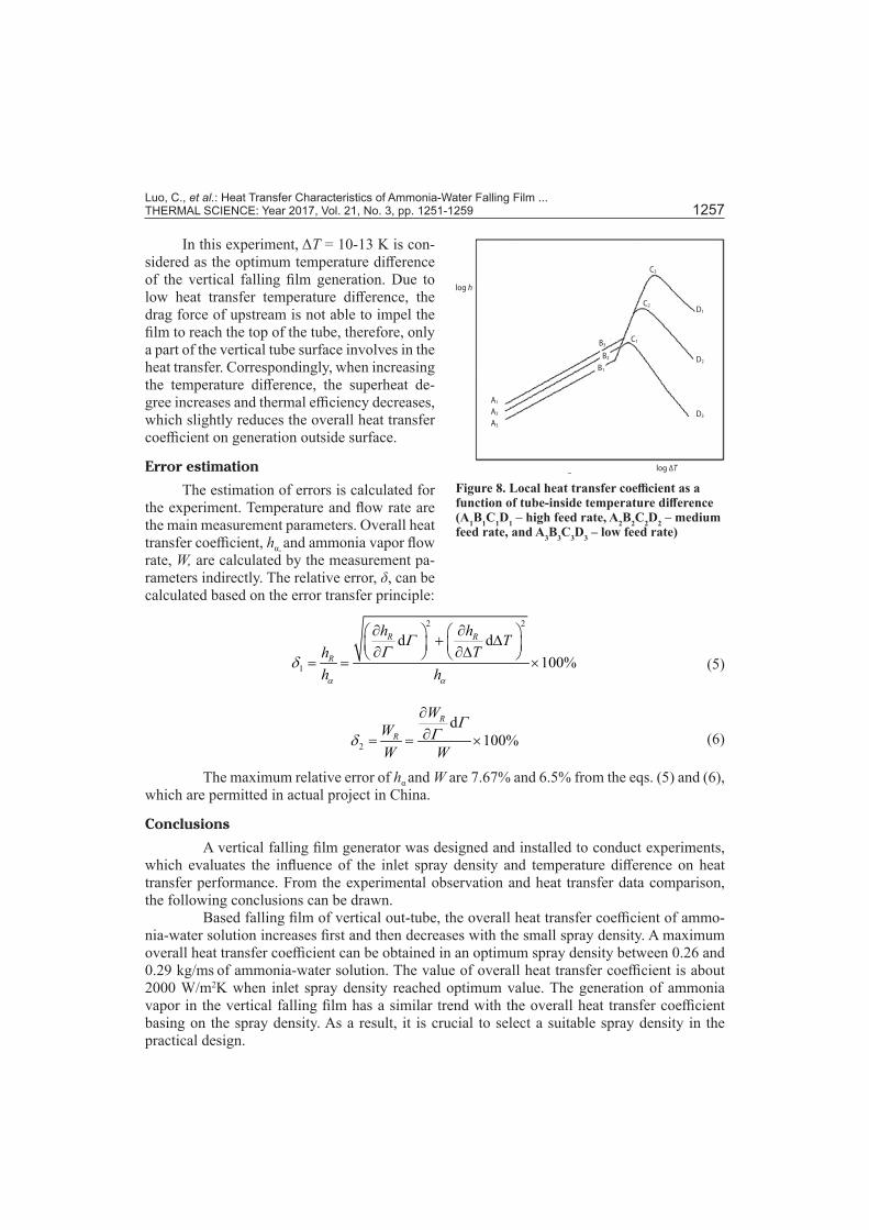
Figure 7 shows the relationship between the overall heat transfer coefficient, hα, of falling film generation and the hot water temperature difference, ΔT, with different hot water inlet temperature, where the inlet concentrations and spray density of ammonia-water solu-tion is fixed. As shown in fig. 7, hα increases first and then decreases between ΔT = 10 K and ΔT = 13 K. It was explained in [15] that heat transfer coefficient decreases with the increase of ΔT in low number and then increases with high number which is presented in fig. 8, this is con-sistent with our experimental result. Figure 8 presented the variation of heat transfer coefficient with temperature difference the curve in fig. 8 was divided into three segments. The first was the low ΔT segment of AB, in which local heat transfer coefficient increased with an increase in ΔT as the function of hα ∝ΔT 0.53. The BC segment for medium ΔT was in nucleate boiling state. Lo-
cal heat transfer coefficient in this segment was higher than that in the segment of AB because the bubbles generated around the surface of the tube stirred the feed water in-side the vertical tube and intensify the heat transfer. The CD segment stands for high ΔT, which stayed in annular flow region. In this segment, the fluid absorbed the heat to evaporate through the liquid film around the tube inner surface by entire conduction. As the conductive resistance increased with an increase in ΔT, heat transfer coefficient re-duced with an increase in ΔT.
Figure 6. The W-Γ relation with different hot water inlet temperature
1234
1
2
3
4
T = 358.15 K, trendlineT = 353.15 K, trendlineT = 348.15 K, trendlineT = 343.15 K, trendline
0.15 0.17 0.19 0.21 0.23 0.25 0.27 0.29 0.31 0.33 0.35
Γ [kgm–1s–1]
17
15
13
11
9
7
5
W [kgh–1]
Figure 7. The hα-ΔT relation with different hot water inlet temperature
1234
T = 358.15 K, trendlineT = 353.15 K, trendlineT = 348.15 K, trendlineT = 343.15 K, trendline
1
2
3
4
8 10 12 14 16 18 20 22
∆T/K
2250
2000
1750
1500
1250
1000
h a [W
m–2
K–1]
Luo, C., et al.: Heat Transfer Characteristics of Ammonia-Water Falling Film ... THERMAL SCIENCE: Year 2017, Vol. 21, No. 3, pp. 1251-1259 1257
In this experiment, ΔT = 10-13 K is con-sidered as the optimum temperature difference of the vertical falling film generation. Due to low heat transfer temperature difference, the drag force of upstream is not able to impel the film to reach the top of the tube, therefore, only a part of the vertical tube surface involves in the heat transfer. Correspondingly, when increasing the temperature difference, the superheat de-gree increases and thermal efficiency decreases, which slightly reduces the overall heat transfer coefficient on generation outside surface.
Error estimation
The estimation of errors is calculated for the experiment. Temperature and flow rate are the main measurement parameters. Overall heat transfer coefficient, hα, and ammonia vapor flow rate, W, are calculated by the measurement pa-rameters indirectly. The relative error, δ, can be calculated based on the error transfer principle:
2 2
1
d d100%
R R
R
h h TTh
h hα α
ΓΓ
δ
∂ ∂ + ∆ ∂ ∂∆ = = × (5)
2
d100%
R
R
WWW W
ΓΓδ
∂∂= = × (6)
The maximum relative error of hα and W are 7.67% and 6.5% from the eqs. (5) and (6), which are permitted in actual project in China.
Conclusions
A vertical falling film generator was designed and installed to conduct experiments, which evaluates the influence of the inlet spray density and temperature difference on heat transfer performance. From the experimental observation and heat transfer data comparison, the following conclusions can be drawn.
Based falling film of vertical out-tube, the overall heat transfer coefficient of ammo-nia-water solution increases first and then decreases with the small spray density. A maximum overall heat transfer coefficient can be obtained in an optimum spray density between 0.26 and 0.29 kg/ms of ammonia-water solution. The value of overall heat transfer coefficient is about 2000 W/m2K when inlet spray density reached optimum value. The generation of ammonia vapor in the vertical falling film has a similar trend with the overall heat transfer coefficient basing on the spray density. As a result, it is crucial to select a suitable spray density in the practical design.
Figure 8. Local heat transfer coefficient as a function of tube-inside temperature difference (A1B1C1D1 – high feed rate, A2B2C2D2 – medium feed rate, and A3B3C3D3 – low feed rate)
log ∆T
log h
A1
A2
A3
B1
B2
B3
C3
C2
C1
D1
D2
D3
Luo, C., et al.: Heat Transfer Characteristics of Ammonia-Water Falling Film ... 1258 THERMAL SCIENCE: Year 2017, Vol. 21, No. 3, pp. 1251-1259
The overall heat transfer coefficient outside a vertical tube increases first and then decreases with ΔT. The ΔT between 10 K and 13 K is considered as the optimum temperature difference of the vertical falling film generation. Therefore, the vertical falling film generation is suitable for a wide range of driving temperature difference, which proves its superiority in utilizing low-grade surplus heating source.
Using this type of generator driven by a low grade heat source is an improvement on refrigeration technology and power cycle, which will bring great energy efficacy benefits. The falling film generator can be tried to apply in ammonia-water solution absorption chiller.
Acknowledgement
This paper was financially supported by the The National Natural Science Funds (51406212).
Nomenclature
A – heat transfer area, [m2]h – enthalpy of ammonia-water liquid per
mass, [kJkg–1]h' – enthalpy of ammonia vapor per
mass, [kJkg–1]hR – overall heat transfer coefficient of trend
line, [Wm–2K–1]hα – overall heat transfer coefficient of
measurement, [Wm–2K–1]m – liquid mass flow rate, [kgh–1]Q – heat flux of hot water, [W]T – inlet temperature of hot water, [K]ΔT – hot water temperature difference between
inlet and outlet, [K]ΔTm – logarithmic temperature difference of the
test cell, [K]W – ammonia vapor flow rate of
measurement, [kgh–1]
WR – ammonia vapor flow rate of trend line, [kgh–1]
Greek symbols
Γ – inlet spray density of ammonia-water solution, [kgm–1s–1]
δ1 – relative error for overall heat transfer coefficient, [%]
δ2 – relative error for ammonia vapor flow rate, [%]
ξ – inlet concentration of ammonia water solution, [%]
Δξ – ammonia-water solution concentration difference between inlet and outlet, [%]
Subscripts
in – inletout – outlet
Reference[1] Ma, W. B., Deng, S. M., Theoretical Analysis of Low-Temperature Hot Source Driven Two-Stage LiBr/
H2O Absorption Refrigeration System, Int. J. Refrig, 2 (1996), 19, pp. 141-146[2] Kalina, A. I., Combined-Cycle System with Novel Bottoming Cycle, ASME Journal of Engineering for
Gas Turbine and Power, 106 (1984), 4, pp. 737-742[3] Yang, L., et al., Heat-Transfer Characteristics of Climbing Film Evaporation in a Vertical Tube, Experi-
mental Thermal and Fluid Science, 34 (2010), 6, pp. 753-759[4] Chun, K. R., Seban, R. A., Heat Transfer to Evaporating Liquid Film, ASME J. Heat Transfer, 93 (1971),
3, pp. 391-396[5] Kang, Y. T., et al., T., Experimental Correlation of Combined Heat and Mass Transfer for NH3-H2O Fall-
ing Film Absorption, Int. J. Refrigeration, 22 (1999), 4, pp. 250-262[6] Shi, C., et al., Heat Transfer Performance of Lithium Bromide Solution in Falling Film Generator, Int. J.
of Heat and Mass Transfer, 53 (2010), 15-16, pp. 3372-3376[7] Fujita, T., Ueda, T., Heat Transfer to Falling Liquid Films and Film Breakdown, Int. J. Heat Mass Trans-
fer, 21 (1978), Feb., pp. 109-118[8] Xia, Z. Z., et al., Capillary-Assisted Flow and Evaporation inside Circumferential Rectangular Micro
Groove, Int. J. Heat Mass Transfer, 52 (2009), 3-4, pp. 952-961[9] Xia, Z. Z., et al., Experimental Investigation of Capillary-Assisted Evaporation on the Outside Surface of
Horizontal Tubes, Int. J. Heat Mass Transfer, 51 (2008), 15-16, pp. 4047-4054

Luo, C., et al.: Heat Transfer Characteristics of Ammonia-Water Falling Film ... THERMAL SCIENCE: Year 2017, Vol. 21, No. 3, pp. 1251-1259 1259
[10] Parizhskiy, O. V., et al., Study of Boiling Heat Transfer with a Falling Film of Refrigerant, Heat Trans-fer-Soviet Res, 4 (1972), 4, pp. 43-47
[11] Zeng, X., et al., Experimental Investigation on Ammonia Spray Evaporator with Triangular-Pitch Plain-Tube Bundle, Part II: Evaporator Performance. Int. J. of Heat and Mass Transfer, 44 (2001), 11, pp. 2081-2092
[12] Yang, L., Shen, S., Experimental Study of Falling Film Evaporation Heat Transfer outside Horizontal Tubes, Desalination, 220 (2008), 1, pp. 654-660
[13] Xu, L., et al., Heat-Transfer Film Coefficients of Falling Film Horizontal Tube Evaporators, Desalinaton, 166 (2004), 15, pp. 223-230
[14] Killion, J. D., Garimella, S., A Critical Review of Models of Coupled Heat and Mass Transfer in Fall-ing-Film Absorption, Int. J. of Refrigeration, 24 (2001), 8, pp. 755-797
[15] Coulson, M., Mcnelly, M. J., Transfer in a Climbing Film Evaporator, Part II, Chem. Eng. Res. Des. 34 (1956), pp.247-257
Paper submitted: May 15, 2015Paper revised: September 25, 2015Paper accepted: November 23, 2015
© 2017 Society of Thermal Engineers of SerbiaPublished by the Vinča Institute of Nuclear Sciences, Belgrade, Serbia.
This is an open access article distributed under the CC BY-NC-ND 4.0 terms and conditions
