heat exchangers: effectiveness-ntu analysiswhitty/chen3453/lecture 24... · overall heat transfer...
TRANSCRIPT
Heat Exchangers:Effectiveness-NTU Analysis
Sections 11.4 to 11.5
CH EN 3453 – Heat Transfer
Reminders…• Homework #8 due today
– Units on problem 9, part (b) are obviously wrong; area should be m2 and not kW
• “Experimental” section of report due today– Turn in to ChE office by 4:00 PM
• Homework #9 due Friday Nov 7
• Project Theory section due Friday next week
• Cody will teach class Monday and Wednesday next week, and will give the help session on Wednesday

Near-Term Schedule• M 3 Nov Heat exchanger design, analysis Cody
• W 5 Nov Alternative to ε-NTU approach Cody
• F 7 Nov Natural convection, boiling Kevin
• M 10 Nov Convection + HX review Kevin
• W 12 Nov MIDTERM #2 Kevin
• F 14 Nov Introduction to radiation Kevin
• M 17 Nov Blackbody radiation Bethany
• W 19 Nov Radiation from real surfaces Bethany
• F 21 Nov Solar and environmental radiation Kevin
REVIEW:Log-Mean Temperature Difference
Cocurrent flow (parallel flow) Countercurrent flow
q =UAΔTlm
REVIEW:Overall Heat Transfer Coefficient
• Essential requirement for heat exchanger design and performance calculations
• Contributing factors – Convection between the two fluids and solid– Conduction of the solid separator– Potential use of fins in one or both sides– Time-dependent surface fouling
• General expression (c and h = cold and hot)
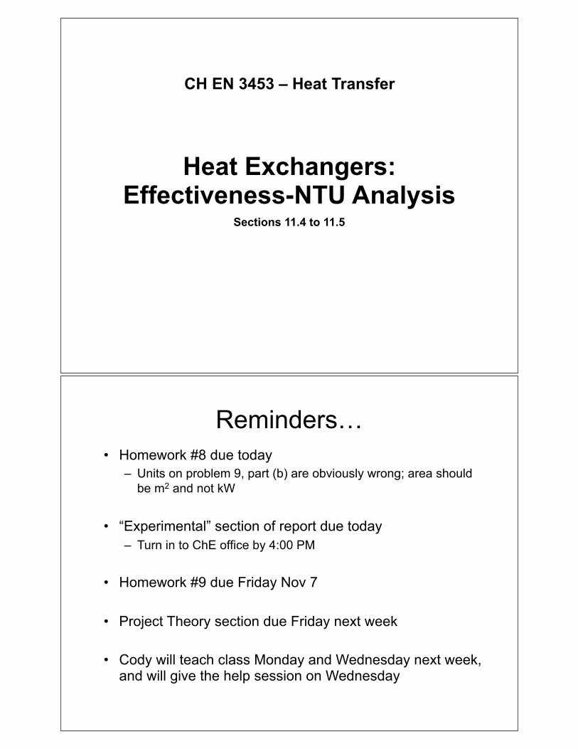
Example – Book Problem 11.5Transfer of energy from hot flue gases passing through an annular region (od=60 mm) to pressurized water flowing through inner tube (id=24 mm; od=30 mm). Eight struts each 3 mm thick connect the tubes. Made of carbon steel (k = 50 W/m·K). Water at 300 K flows at 0.161 kg/s through inner tube while flue gas at 800 K flows through annulus, maintaining a convection coefficient of 100 W/m2·K on both struts and outer surface of inner tube.
What is the heat transfer rate per unit length of tube?

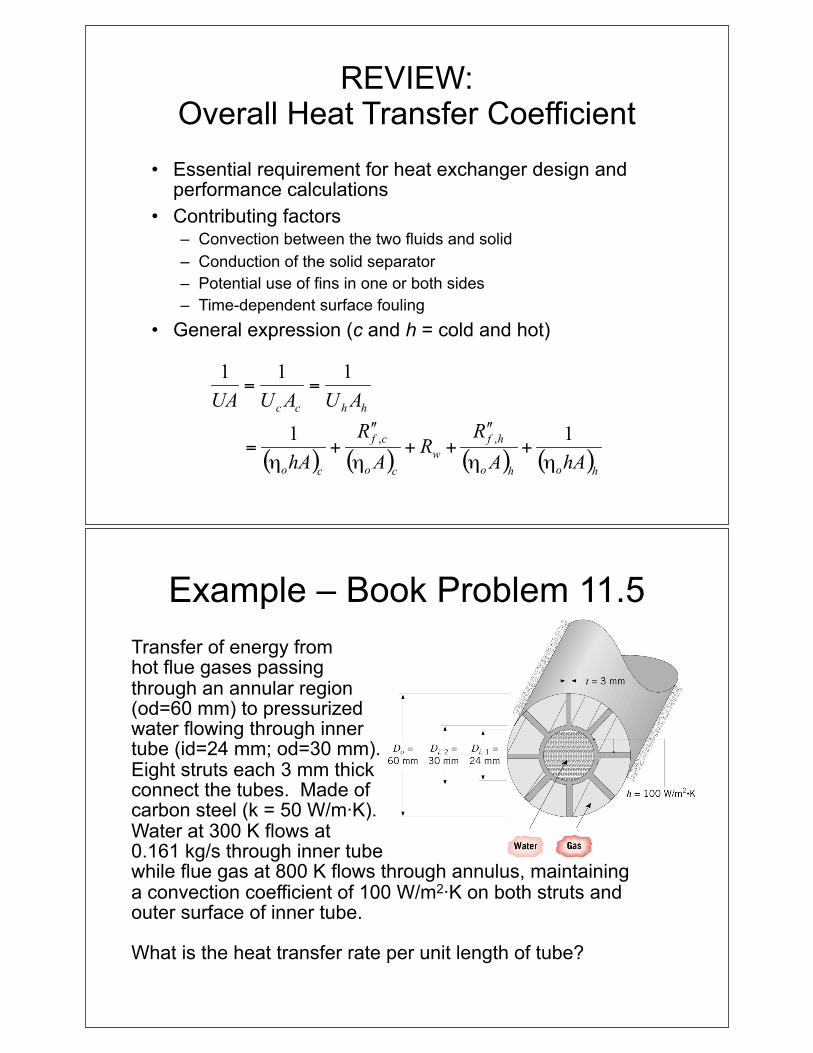
Parallel-Flow Heat Exchanger
Counterflow Heat Exchanger
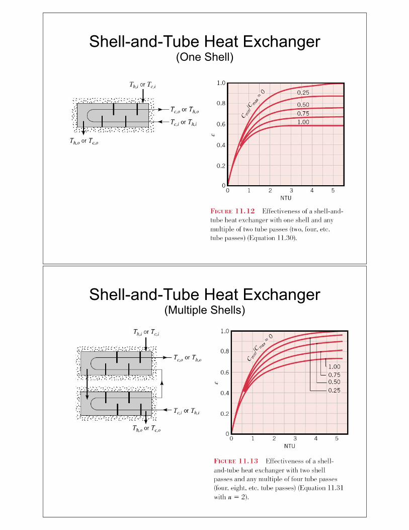
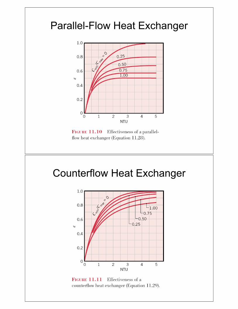
Shell-and-Tube Heat Exchanger(One Shell)
Shell-and-Tube Heat Exchanger(Multiple Shells)

Cross-Flow Heat Exchanger(Unmixed-Unmixed)
Cross-Flow Heat Exchanger(Mixed-Unmixed)
Solid curves:Cmin mixedCmax unmixed
Dashed curves:Cmin unmixedCmax mixed

Example – Book Problem 11.22A shell-and-tube heat exchanger must be designed to heat 2.5 kg/s of water from 15 to 85°C. The heating is to be accomplished by passing hot engine oil, which is at 160°C, through the shell side of the exchanger. The oil provides an average convection coefficient ho = 400 W/m2·K on the outside of the tubes. Ten tubes pass water through the shell. Each tube is thin walled, of diameter D=25 mm, and makes eight passes through the shell. If the oil leaves the exchanger at 100°C, what is the flow rate? How long must the tubes be to accomplish the desired heating?