review: convection and heat exchangerswhitty/chen3453/lecture 28 - convection review.pdf · review:...
TRANSCRIPT

Review:Convection and
Heat Exchangers
Chapters 6, 7, 8, 9 and 11
CH EN 3453 – Heat Transfer
Reminders…
• Midterm #2 Wednesday at… 8:15 AM– Review tomorrow 3:30 PM in WEB L104 (I think)
• Project Results and Discussion due Friday at 4:00PM– Turn in to Chem Engineering office– Write text, not just equations! Target 300-500 words.– Explain it to e.g. your manager (a non-engineer)
• Project Intro and Conclusions due Friday, Nov 21– Use separate paper for each– Put your name on each section
• Many homework assignments have not been picked up

CHAPTER 6:Introduction to Convection
• Boundary layers– Velocity– Thermal
• Boundary layer equations
Three Boundary Layers

Laminar and Turbulent Flow
Laminar and Turbulent Flow
Figure 6.8 Variation of velocity boundary layer thickness δ and the local heat transfer coefficient h for flow over an isothermal flat plate.
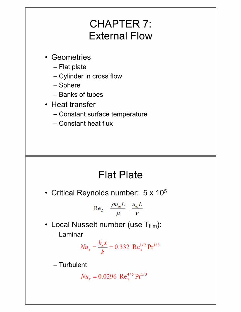
CHAPTER 7:External Flow
• Geometries– Flat plate– Cylinder in cross flow– Sphere– Banks of tubes
• Heat transfer– Constant surface temperature– Constant heat flux
Flat Plate• Critical Reynolds number: 5 x 10⁵
• Local Nusselt number (use Tfilm):– Laminar
– Turbulent

Flat Plate• Average Nusselt number
– Laminar
– Turbulent (tripped at leading edge)
– Transition
• Unheated starting length
Example: Problem 7.16
Consider a rectangular fin that is used to cool a motorcycle engine. The fin is 0.15 m long and at a temperature of 250°C, while the motorcycle is moving at 80 km/h in air at 27°C. The air is in parallel flow over both surfaces of the fin, and turbulent flow conditions may be assumed to exist throughout.
What is the rate of heat removal per unit width of the fin?

Cylinder in Cross Flow
• Average Nusselt number (all ReD)
Example: Problem 7.45
A pin fin of 10-mm diameter dissipates 30 W by forced convection to air in cross flow with a Reynolds number of 4000. If the diameter of the fin in doubled and all other conditions remain the same, estimate the fin heat rate. Assume the fin to be infinitely long.

Flow over a Sphere
• Average Nusselt number
Flow Across Banks of Tubes

Banks of Tubes (cont.)
Example: Problem 7.88A tube bank uses an aligned arrangement of 30 mm diameter tubes with ST = SL = 60 mm and a tube length of 1 m. There are 10 tube rows in the flow direction and 7 tubes per row. Air with upstream conditions of T = 27°C and V∞ = 15 m/s is in cross flow over the tubes, while a tube wall temperature of 100°C is maintained by steam condensation inside the tubes.
Determine the temperature of air leaving the tube bank.

Table 7.9 - Bookmark It!
CHAPTER 8:Internal Flow
• Basics– Velocity profiles– Mean velocity, mean temperature
• Geometries– Circular tubes– Non-circular tubes– Concentric annulus
• Heat transfer– Constant surface temperature– Constant heat flux

Internal Flow
Internal Flow Calculations
• Reynolds number (critical = 2300)
• Hydraulic diameter for non-circular tubes
• For uniform surface temperature

Laminar Flow in a Circular Tube
Laminar Flow: Non-Circular Tube

Turbulent Flow• Circular or noncircular tube with small
temperature diffs (Dittus-Boelter)

Example: Problem 8.26
Ethylene glycol flows at 0.01 kg/s through a 3 mm diameter, thin-walled tube. The tube is coiled and submerged in a well-stirred water bath maintained at 25°C. If fluid enters the tube at 85°C, what heat rate and tube length are required for the fluid to leave at 35°C?
CHAPTER 9:Free (Natural) Convection
• Fundamentals– Buoyancy– Boundary layer development
• Geometries– Vertical surface– Horizontal plates– Long horizontal cylinder– Spheres– Vertical parallel plate channels– Enclosures/cavities
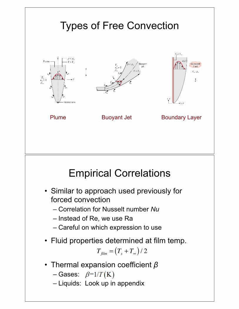
Types of Free Convection
Plume Buoyant Jet Boundary Layer
Empirical Correlations• Similar to approach used previously for
forced convection– Correlation for Nusselt number Nu– Instead of Re, we use Ra– Careful on which expression to use
• Fluid properties determined at film temp.
• Thermal expansion coefficient β– Gases:– Liquids: Look up in appendix
Tfilm = Ts + T∞( ) / 2

Flow over Vertical Plate
• Rayleigh Number:
• Laminar Flow (RaL < 109):
• All Conditions:
(9.25)
(9.27)
(9.26)
Example: Problem 9.13
A household oven door of 0.5-m height and 0.7-m width reaches an average surface temperature of 32°C during operation. Estimate the heat loss to the room with ambient air at 22°C.

CHAPTER 11:Heat Exchangers
• Basics– Overall heat transfer coefficient– Phase change heat transfer one one side
• Heat exchanger configurations– Parallel flow– Counterflow
• Multiple shells• Multiple tube passes
– Cross-flow• Analysis approaches
– Log-mean temperature difference (design)– Effectiveness-NTU (performance and design)– Modified LMTD (design - fancy configurations)
Overall Heat Transfer Coefficient
• Contributing factors – Convection between the two fluids and solid– Conduction of the solid separator– Potential use of fins in one or both sides– Time-dependent surface fouling
• General expression (c and h = cold and hot)

Log-Mean Temperature Difference
Cocurrent flow (parallel flow) Countercurrent flow
q =UAΔTlm
Special Operating Conditions
"heat capacity rate"

Effectiveness-NTU Approach• Effectiveness:
• NTU (Number of Transfer Units):

Parallel-Flow Heat Exchanger

Counterflow Heat Exchanger
Shell-and-Tube Heat Exchanger(One Shell)

Shell-and-Tube Heat Exchanger(Multiple Shells)
Cross-Flow Heat Exchanger(Unmixed-Unmixed)

Cross-Flow Heat Exchanger(Mixed-Unmixed)
Solid curves:Cmin mixedCmax unmixed
Dashed curves:Cmin unmixedCmax mixed
Example: Problem 11.25In a dairy operation, milk at a flow rate of 250 liter/hour and a cow body temperature of 38.6°C must be chilled to a safe-to-store temperature of 13°C or less. Ground water at 10°C is available at a flow rate of 0.72 m3/h. The density and specific heat of water are 1030 kg/m3 and 3860 J/kg·K.
(a) Determine the UA product of a counterflow heat exchanger required for the chilling process. Determine the length of the exchanger if the inner pipe has a 50 mm diameter and the overall heat transfer coefficient is U = 1000 W/m2·K.
(b) Determine the outlet temperature of the water.
(c) using the UA from part a, determine the milk outlet temperature if the water flow rate is doubled.