healthcare facility plumbing design - plumbing engineer
TRANSCRIPT

Healthcare FacilityPlumbing Design
ALSO INSIDE:• Warming up to Snowmelt Design• Understanding Solar Collector Efficiency• Grease Recovery Device Helps Restaurant Alleviate Discharge Problem
Find us on Facebook & Twittertwitter.com/plumbingeng
facebook.com/PlumbingEngineer
Scan with your smart phone or visit online at qr.qg.com/CnS8jh to renew your subscription to Plumbing Engineer today!
pe11_pgs_01_03rev_Layout 1 10/31/11 10:55 AM Page 1

WHERE COULD YOU USE WEBSTONE INNOVATION?
Technical information available at:www.webstonevalves.com/pro-pal(800) 225-9529
G U A R A N T E E D F O R L I F E
BOILER
Supply
Return
INDIRECTWATERHEATER
BASEBOARD HEATER
SNOWMELT ZONE
Heat Exchanger
LOW TEMP RADIANT FLOOR MANIFOLD
LOW TEMP RADIANT FLOOR PANEL
SPARE
SPARE
Temperature Gauge
Back�owPreventer
PressureReducing
ValveExpansion
Tank
Supply
Return
HIGH TEMP CONTROL PANEL
SPARE
SUPPLY FEED
SPARE
B
A
A
A
D
C
A
K
J
H
A
G
GE
I
F F
F
F
F
I
J
J J
J J H
K
M
L
A
F
A
A
Heatt
A
G
G
K
F
F
H
A Union Ball DrainB T-DrainC Purge & FillD Air Separator
E Expansion Tank Pro Service Valve
F Isolator w/Rotating Flange
G Purge TeeH Ball DrainI Ball Valve w/Hose EndJ Brass Ball Valve
K Isolator w/Rotating Flange & Drain
L HydroCore
M HydroCore Complete Near Boiler Piping Kit
H
Compact Design
Reversible handle directs � ow into the drain from either side of the ball
T-Flow Ball
Normal HandleClosed Position
Reversed HandleClosed Position
Reversed HandleOpen Position
Normal HandleOpen Position
• Hi-Flow Hose Drain
• Eliminates 3 Components
• Avoids 3 Leak Paths
• Saves Nearly 30 Minutes of Labor
Circle 1 on Reader Reply Form on page 54
pe11_pgs_01_03_Layout 1 10/27/11 12:30 PM Page 2

Circle 2 on Reader Reply Form on page 73
pe11_pgs_01_03_Layout 1 10/27/11 12:30 PM Page 3

Page 4/Plumbing Engineer November 2011
���������������������� ����� �
����������• Warming up to Snowmelt Design• Understanding Solar Collector Efficiency• Grease Recovery Device Helps Restaurant Alleviate Discharge Problem
Scan with yoursmart phone and
follow us on Twitter
Scan with your smart phone or visit online at qr.qg.com/CnS8jh to renew your subscription to Plumbing Engineer today!
INDUSTRY NEWS &OTHER DEPARTMENTS
8 | ACCA launches Radiant &Hydronics Council
8 | ITT board of directors approvesspinoffs of Xylem and ITT Exelis
8 | NFPA symposium slated forDecember
10 | IAPMO, PMI sign MoU
10 | University of Maryland’sWatershed house wins top spot atSolar Decathlon
10 | BrassCraft celebrates 65 years
10 | SolarLogic announces new software patent
12 | Taco tops off Innovation &Development Center
12 | AFSA elects chairman
50 | NEW PRODUCTS
52 | CLASSIFIEDS
52 | INDUSTRY MOVERS
54 | AD INDEX
COLUMNS
Volume 39, Number 11, November 2011
FEATURES
INSIDE THIS ISSUE
6 Editor’s Letter: Learning to Fly14 Designer’s Guide: Highland Tank and Flight 9318 Code Classroom: International Plumbing Code changes due soon20 FPE Corner: Water mist fire protection systems, Part 224 Solar Solutions: The Solar Combi 101-Mini: for the cabin or guest house
Healthcare Facility Plumbing DesignHospitals and healthcare facilities are among themost complex building types to design because theyhave critical plumbing systems.
Story on page 28
Warming up to Snowmelt TechnologyMost of us in the trade readily see the value ofsnowmelt systems. Yet, many building and facility own-ers have yet to embrace them.
Story on page 38
Understanding Solar Collector EfficiencySolar thermal collector efficiency is being used inengineering analysis where the performance of twoproducts is compared head to head to decide whichproduct is “better.”
Story on page 44
Grease Recovery Grease recovery device helps restaurant alleviate discharge problem.
Story on page 48
Photo credit: University of Michigan’sC.S. Mott Children’s Hospital.
pe11_pgs_04_05rev_Layout 1 10/28/11 8:09 AM Page 4

Circle 3 on Reader Reply Form on page 54
pe11_pgs_04_05rev_Layout 1 10/28/11 8:09 AM Page 5
Pink Floyd’s 1987 single “Learning to Fly,” from the Momentary Lapse ofReason CD, could be argued as a strong analogy for the band’s rebirthafter the departure of lead man Roger Waters, and David Gilmour’s pilot-
ing of the “new” Floyd, post-Waters.It takes strong leadership to captain and redirect a wayward vessel — in this
case, the radiant and hydronics’ past attempts at leading successful industry thinktanks — but I do think ACCA’s newly formed Radiant & Hydronics (RHC) coun-cil is headed in the right direction to become a successful organization. Createdfrom the need to have a viable radiant organization, the RHC is now led by someof the biggest names in the radiant/hydronics industry, and their veteran leader-ship can’t be understated. “Since it is an organization of, by, and for the contrac-tor, it gives us one strong voice in advocacy, while providing services specific toradiant professionals through the council,” says Dan Foley, first chairman of theRHC Advisory Council. Foley stresses the fact that this is a contractor-led orga-nization, leaving manufacturers beyond the white lines.
“This is a win-win for the industry,” says Dave Yates, owner of F.W. Behler,Inc., York, Pa. “The more information relating to hydronics out there can onlybe a good thing for the industry.” And the members on this new council will bededicated to sharing information and enhancing the awareness of radiant.
“Radiant contractors have been seeking a dynamic, contractor-focused orga-nization for some time; many have asked ACCA to expand an emphasis into thatsector,” said Joe Nichter, ACCA 2011 - 2012 chairman. “The RHC will providefirst-class representation and services for radiant and hydronics professionalsthat wish to be the best in their field.”
Some of the new features of RHC:• The addition of a new Radiant & Hydronics educational track at the 2012
ACCA Conference, held March 5 – 8 in Las Vegas;• Development of a new, two-day educational meeting specifically for radiant
and hydronics professionals — the Hydronics Roundtable;• Development of a new radiant-specific section of the ACCA website; and• Inclusion of RHC input in ACCA’s broader activities in government relations,
industry advocacy, education, communications and standards development.“I’m looking forward to a well-focused and experienced approach to the RHC
creation and implementation. ACCA has had a long-standing reputation and histo-ry to make this happen. If hydronics is to be a player in the market, the RHC is thegroup to ‘get ’er done,’” says Bob “hot rod” Rohr. “I’m looking forward to theexchange with current and long-time ACCA members. With a slow economy, thisis an ideal time to access more training, form alliances and learn to promote newtechnologies. Fasten your seatbelt, this should be an exciting journey.” n
To see the full ACCA RHC news release, turn to page 8.
Editorial, Advertising,Production, Accounting and
Administrative Offices
2165 Shermer Rd., Suite ANorthbrook, IL 60062
(847) 564-1127 • Fax: (847) 564-1264E-mail: [email protected]
OwnerTom M. Brown
Editorial & Production StaffJohn Mesenbrink, Editorial DirectorMarilyn Cunningham, Associate EditorCate C. Brown, Production ManagerMark Bruno, Art Director/Prepress
ContributorsTimothy Allinson, P.E., Designer’s Guide
Sam Dannaway, Fire ProtectionRon George, CPD, Code Classroom
Dan Foley, HydronicsBob “Hot Rod” Rohr, Green SystemsBristol Stickney, Solar Solutions
Sales StaffBrad Burnside, Publisher East2165 Shermer Rd, Suite A, Northbrook,IL 60062 Phone: 847/564-1127 Cell: 224/659-3984Fax: 847/564-1264E-mail: [email protected]
David Schulte Midwest, South and E. Canada2165 Shermer Rd, Suite A, Northbrook,IL 60062 Phone: 847/564-1127 Cell: 847/420-4686Fax: 847/564-1264E-mail: [email protected]
Diane Spangler West, Texas and W. CanadaPO Box 9802, Fountain Valley, CA92728 Phone: 714/839-6700Fax: 714/839-6777E-mail: [email protected]
Learning to flyNew Radiant & Hydronics Council spreading its wings with support from ACCA
Editor’s Letter
Page 6/Plumbing Engineer November 2011
PLUMBING ENGINEER(USPS 567-950) ISSN 0192-1711
PLUMBING ENGINEER (USPS 567-950) ISSN 0192-1711 is published monthly by TMB Publishing Inc., 2165 ShermerRd., Suite A, Northbrook, IL 60062. Phone (847) 564-1127, Fax (847) 564-1264. Magazine is free to those who design andspecify plumbing/piping systems in commercial, industrial, institutional and governmental buildings; as well as governmentofficials and plumbing inspectors. Subscription rates for U.S. and Canada: $50 for one year, $90 for two years. Other coun-tries: $300 per year. Periodical postage paid at Northbrook, IL, and additional mailing offices. POSTMASTER: Change ofaddress should be sent to Plumbing Engineer, 440 Quadrangle Dr., Suite E., Bolingbrook, IL 60440. Material and opin-ions contained in contributed articles are the responsibility of the authors, not of TMB Publishing Inc., Plumbing Engineermagazine or its Editorial Advisory Board. The publisher cannot assume responsibility for any claims made by advertisers.Copyright © 2011 TMB Publishing Inc. All rights reserved. Volume 39, Number 11. Plumbing Engineer is microfilmed byUniversity Microfilms, Ann Arbor, MI, and indexed by Engineering Index Inc. Publications Mail Agreement No. 41499518.Return Undeliverable Canadian Addresses to PO Box 503, RPO West Beaver Creek, Richmond Hill ON L4B 4R6
John Mesenbrink, editorial [email protected]
pe11_pgs_06_07rev_Layout 1 10/31/11 7:39 AM Page 6

Something’s happening here
Leonard’s New Building Management System Interface Knows
Because you need real-time, accurate temperature monitoring to know whensomething is amiss…integrating Leonard’s newBuilding Management SystemInterface gives you everythingyou need. Providing you exactlywhat you want: real-timemonitoring of outputtemperature.
Through the use of an Ethernetconnection with integratedbuilding management software,BMSI gives real-time, accuratereadings to monitor temperedwater to the domestic hot watersystem. Integrate BMSI withinstalled mixing valves orintegrate with a complete watertemperature control system, for significant cost savings.
• Interface with buildingmanagement system
• Constant, real-time monitoringof output water temperature
• Simplifies maintenanceprotocol
• MODBUS TCP/IP protocol• Digital display
Leonard’s valves give “integratedcontrol” for all water temperingdesign needs. Before your next project, be sure to visitwww.leonardvalve.com or callour free technical support hotlineat 888-797-4456.
Integrated control with everyvalve from the leader intemperature valves, Leonard Valve.
NEW
Leonard...the right mix.
Circle 4 on Reader Reply Form on page 54
pe11_pgs_06_07rev_Layout 1 10/31/11 7:39 AM Page 7

Page 8/Plumbing Engineer November 2011
Industry News
WashingTOn — The air conditioning contractors ofamerica (acca), the nation’s largest organization ofindoor environment and energy services contractingbusinesses, has launched a new Radiant & hydronicscouncil (Rhc) within acca to provide specific ser-vices to this vital segment of the hVac/R industry.
“Radiant contractors have been seeking a dynamic,contractor-focused organization for some time; manyhave asked acca to expand an emphasis into that sec-tor,” said Joe nichter, acca 2011 - 2012 chairman.“The Rhc will provide first-class representation and ser-vices for radiant and hydronics professionals that wish tobe the best in their field.”
The changing indoor environment sector requires con-tractors of all kinds to master a wide variety of technolo-gies, including air, hydronic, solar, geothermal and otheralternative energy services. The addition of the Rhc tothe acca umbrella is a key part of the association’sstrategic plan to help its members compete in the mod-ern business climate.
The Rhc will be guided by an advisory committee com-prised of the nation’s leaders in this vital industry segment.The first chairman of the Rhc advisory council will bePlumbing Engineer and Phc News columnist Dan Foley.Foley is president of Foley Mechanical in lorton, Virginia,a recognized leader among hydronics contractors and apast chairman of the Radiant Panel association (RPa).
in addition to Foley, others serving on the Rhcadvisory committee are:
• greg Jannone, William Jannone & son, BoundBrook, n.J. (past chair, RPa)
• John abularrage, advanced Radiant Design, stoneRidge, n.y.
• Brian stack, stack heating & cooling, avon, Ohio• John siegenthaler, appropriate Designs, holland
Patent, n.y.• Mark hottel, harvey W. hottel inc, gaithersburg, Md.• Dave yates, F.W. Behler inc., york, Pa.
ACCA launches Radiant & Hydronics Council
More Industry News on page 10
• Bob “hot Rod” Rohr, caleffi, Milwaukee, Wis. (pastchair, RPa)
• Bill shady, PE, sustainable Design and ProductManagement, santa cruz, calif.
“as a longtime active member of associations in boththe air and radiant field, i am excited to see acca cre-ate this new organization,” said Foley. “it is definitelytime for the many different elements of the indoor envi-ronment industry to come together under one umbrellafor the betterment of all contractors. acca offers us anincredible opportunity to do just that. since it is an orga-nization of, by and for the contractor, it gives us onestrong voice in advocacy, while providing services spe-cific to radiant professionals through the council.”
The Rhc’s initial scope of work includes:• The addition of a new Radiant & hydronics educa-
tional track at the 2012 acca conference, held March 5– 8 in las Vegas;
• The launch of a new monthly e-newsletter, RadiantTrends, specifically for Rhc members;
• Development of a new, two-day educational meetingspecifically for radiant and hydronics professionals —the hydronics Roundtable — to be held in fall 2012 aspart of acca’s annual contracting Week;
• Development of a new radiant-specific section of theacca website, featuring webinars, articles andresources exclusively for Rhc members;
• addition of a hydronics-specific contractorDirectory on the acca website;
• inclusion of Rhc input in acca’s broader activitiesin government relations, industry advocacy, education,communications and standards development.
Membership in Rhc will be open to all acca mem-ber companies; in addition to acca membership dues, anominal Rhc fee of $95 per year will be charged for par-ticipation in the council. Details about the Rhc, includ-ing information on how to join, will soon be available onacca’s website at www.acca.org.
ITT board of directors approves spinoffs of Xylem and ITT Exelis
WhiTE Plains, n.y. — iTT corporation’s board of direc-tors has approved the distribution to its shareholders of allthe outstanding shares of Exelis inc., its defense and infor-mation solutions business, which will also be known asiTT Exelis and Xylem inc., its water technology and ser-vices business, which will result in three distinct, publiclytraded companies. Each iTT shareholder of record as ofthe close of business on October 17, 2011, the record datefor the distribution, received one share of iTT Exelis com-mon stock and one share of Xylem common stock for eachshare of iTT common stock held as of the record date. TheiTT Board also approved a 1:2 reverse stock split for iTT,which will become effective after market close on October31, 2011, the distribution date for the spinoffs.
NFPA symposium slated for December
Quincy, Mass. — The national Fire Protectionassociation (nFPa) and its affiliate, the Fire ProtectionResearch Foundation (the Foundation) will host a 1-dayalternative Energy Technologies and Electrical safetystandards symposium December 6, 2011 in atlanta.The symposium comes at a significant turning point, asmore businesses and consumers are turning to alternativeenergy sources and technologies. Developments in thefield are proliferating at an ever increasing rate, and newquestions about safety and reliability continue to beraised.
Visit nFPa’s website at www.nfpa.org/aEsymposiumfor more information or to register online or call800/344-3555, Monday – Friday, 8:30 a.m. – 5:00 p.m.(EsT).
pe11_pgs_08_13rev_Layout 1 10/27/11 9:35 AM Page 8

Circle 5 on Reader Reply Form on page 54
pe11_pgs_08_13rev_Layout 1 10/27/11 9:35 AM Page 9

operating the most cost effective,energy efficient and functional solar-powered homes. The University ofMaryland’s Watershed house, whichfeatures an Uponor PeX plumbingsystem, came out on top, with a totalof 951.151 points out of 1,000.
Two other solar decathlon homesalso featured Uponor: sixth-placesouthern california institute ofarchitecture (sci-arc) andcalifornia institute of Technology(caltech) team, and ninth-place TeamMassachusetts, which includedMassachusetts college of art anddesign and the University ofMassachusetts at lowell.
InnoFlue the first UL‐1738 list-ed polymeric vent system inNorth America.
alBaNy, N.y. — centrotherm ecosystems, a leader in polypropyleneventing technology, announced thattheir innoFlue® branded, single wall,flexible and concentric vent systemshave been tested and are now listed toUl‐1738. To date, according to thecompany, innoFlue is the only plasticvent that has earned this listing underthe only standard in the U.s. that isspecifically designed to test and listvent systems for category ii & ivheating appliances.
SolarLogic announces new software patent
saNTa Fe, N.M. — solarlogic llc, aNew Mexico solar heating technologycompany, has received U.s. patentapproval of its slash-d design soft-ware. slash-d uses a small set ofinputs about a building requiring asolar heating system and delivers ananalysis of solar heat availability andutilization, a system parts list, estimat-ed cost and a detailed piping schemat-ic, enabling any qualified heating con-tractor to proceed with quoting, pro-curement and installation of a solarhome heating system.
in addition, slash-d outputs adata file used by solarlogic’s com-plementary flagship product, the
Page 10/Plumbing Engineer November 2011
Continued on page 12
BrassCraft celebrates 65 years
Novi, Mich. — BrasscraftManufacturing company, a pioneerin the development of plumbingproducts, is celebrating its sixty-fifthanniversary. Founded in 1946,Brasscraft is headquartered in Novi,Michigan, and has grown to includedistribution and manufacturing facili-ties in Michigan, california, Northcarolina and Texas.
The company provides a completerange of long-lasting plumbing sup-plies to professionals in the new con-struction and repair/remodel markets.
Brasscraft Manufacturing is dedi-cated to providing world-class execu-tion with our channel partners toremain a trusted and preferred partnerfor plumbing professionals. We thankthe plumbing community for our suc-cess over the last 65 years and lookforward to their continued support inthe future. For more information,visit www.brasscraft.com.
IAPMO, PMI sign MoU
RolliNg MeadoWs, ill. — Theinternational association of Plumbingand Mechanical officials (iaPMo)and Plumbing Manufacturersinternational (PMi) have entered intoa Memorandum of Understanding(MoU) specifically detailing ways inwhich the two venerable organiza-tions will work together to jointlyadvance and promote mutual industryinterests as related to education, train-ing and advocacy. iaPMo ceo gPRuss chaney and PMi executivedirector Barbara c. higgens signedthe MoU on october 13 inWashington, d.c. For more informa-tion, www.pmihome.org.
University of Maryland’sWatershed house wins topspot at Solar Decathlon
WashiNgToN — on oct. 3, the U.s.department of energy announced thewinner of the 2011 solar decathloncompetition, which awards collegiateteams for designing, building andCircle 6 on Reader Reply Form
on page 54
Industry NewsContinued from page 8Pure Water by Watts
offers a complete line of innovative solutions for the
delivery of better-than-bottledwater quality.
Commercial/Industrial WaterConditioning & RO Systems
Residential Drinking WaterSystems
Whole House Water Conditioning Systems
Light Commercial WaterConditioning & RO Systems
Commercial Water Softeners
A Watts Water Technologies Company
pe11_pgs_08_13rev_Layout 1 10/27/11 9:35 AM Page 10

Refreshing.
Introducing Pure Water by Watts
Pure Water by Watts is a nice change. Your customers will like
the purity of their water and the efficiency of their systems. What you’ll find refreshing is how straight-forward our systems are to under-stand and specify. The broad Pure Water array of water quality solu-tions covers all the bases, from ultra-filtration to anti-scale and reverse osmosis products.
nnovative water technologies your customers want
disinfection and conditioning
solutions for every need
kits and replacement cartridges
design support
watts.com/purewater
Scan this QR code to view our entire Pure Water line
A Watts Water Technologies Company
Circle 7 on Reader Reply Form on page 54
pe11_pgs_08_13rev_Layout 1 10/27/11 9:35 AM Page 11

Circle 8 on Reader Reply Form on page 54
ence rooms, a business center and functional labs for test-ing and teaching.
AFSA elects chairman
DALLAS — The American Fire Sprinkler Association(AFSA) has elected Dwight Bateman, founder and presi-dent, Southeast Fire Protection Inc., Houston, chairman ofthe 2011–2012 AFSA board of directors. Bateman was elect-ed during the Wednesday, September 14 board of directors’meeting at the AFSA convention in San Antonio and wasinstalled at the close of the convention.
ASSE, ASPE to develop plumbing dictionary
CHICAgo AnD WeSTLAke, oHIo — The American Societyof Sanitary engineering (ASSe) and the AmericanSociety of Plumbing engineers (ASPe), the two globalleaders serving the sanitary and plumbing engineeringprofessions, have agreed to work together to develop ajoint plumbing dictionary. The dictionary will combinethe current publications issued by each organization,bringing the plumbing community one step closer to hav-ing consistent, globally accepted terminology.
SLIC (SolarLogic Integrated Controller), patented in2010. The SLIC is an integrated hardware-softwaredevice that replaces all conventional and solar-specificheating controls with a single component, is interactiveon the Internet and, because it is loaded with the SLASH-D output as part of installation, requires no programmingupon system start-up and commissioning.
Taco tops off Innovation & Development Center
CrAnSTon, r.I. —Taco marked animportant milestonein the construction ofits new Innovation &Development Center,the centerpiece of its$18 million expan-sion project, withbeam raising and top-ping off ceremonies
in September. The Taco Innovation & Development Center will con-
sist of a 24,037-square-foot addition to the current build-ing. It will be a state-of-the-art learning and training envi-ronment, complete with new classroom spaces, confer-
Page 12/Plumbing Engineer November 2011
Industry NewsContinued from page 10
He’s not only the reigning chess champ of Cedar Hills Village.He’s also our top product design consultant.
At Moen Commercial, we spend many afternoons with folks like Karl. Because the better we know him, the better we’re able to design solutions that meet the unique needs of the elderly. Our faucets, flush valves and shower systems offer ergonomic handles for those with limited mobility or dexterity, temperature controls to prevent scalding, and innovative hands-free technology. Plus, these products comply with Universal Design principles and ADA standards, and are backed with a limited 5-year warranty. All to ensure quality, safety and accessibility. You see, we understand that a tough chess opponent isn’t the only challenge Karl faces throughout the day.
To learn more about how our products are built for the real world, visit www.moencommercial.com or call 800-BUY-MOEN.
©2011 Moen Incorporated CON-HH-1Moen and the Crossed Water Drops device are registered trademarks of Moen Incorporated
pe11_pgs_08_13rev_Layout 1 10/27/11 9:36 AM Page 12

Circle 9 on Reader Reply Form on page 54
pe11_pgs_08_13rev_Layout 1 10/28/11 8:17 AM Page 13
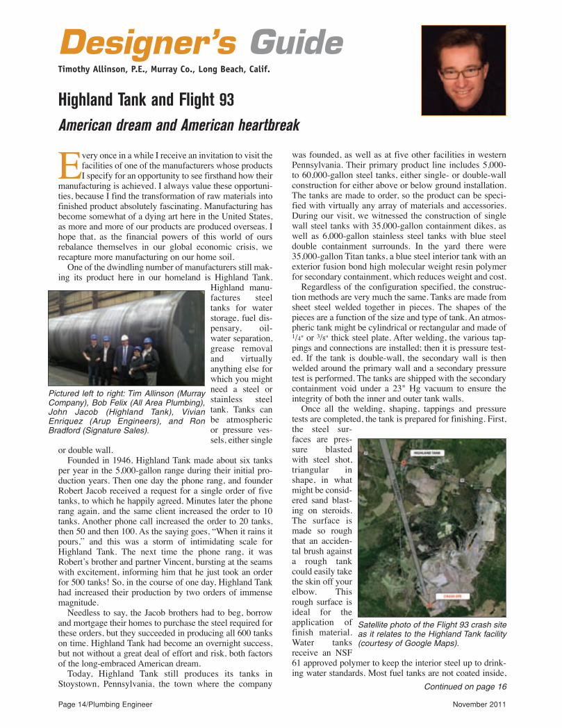
Every once in a while I receive an invitation to visit thefacilities of one of the manufacturers whose productsI specify for an opportunity to see firsthand how their
manufacturing is achieved. I always value these opportuni-ties, because I find the transformation of raw materials intofinished product absolutely fascinating. Manufacturing hasbecome somewhat of a dying art here in the United States,as more and more of our products are produced overseas. Ihope that, as the financial powers of this world of oursrebalance themselves in our global economic crisis, werecapture more manufacturing on our home soil.
One of the dwindling number of manufacturers still mak-ing its product here in our homeland is Highland Tank.
Highland manu-factures steeltanks for waterstorage, fuel dis-pensary, oil-water separation,grease removaland virtuallyanything else forwhich you mightneed a steel orstainless steeltank. Tanks canbe atmosphericor pressure ves-sels, either single
or double wall.Founded in 1946, Highland Tank made about six tanks
per year in the 5,000-gallon range during their initial pro-duction years. Then one day the phone rang, and founderRobert Jacob received a request for a single order of fivetanks, to which he happily agreed. Minutes later the phonerang again, and the same client increased the order to 10tanks. Another phone call increased the order to 20 tanks,then 50 and then 100. As the saying goes, “When it rains itpours,” and this was a storm of intimidating scale forHighland Tank. The next time the phone rang, it wasRobert’s brother and partner Vincent, bursting at the seamswith excitement, informing him that he just took an orderfor 500 tanks! So, in the course of one day, Highland Tankhad increased their production by two orders of immensemagnitude.
Needless to say, the Jacob brothers had to beg, borrowand mortgage their homes to purchase the steel required forthese orders, but they succeeded in producing all 600 tankson time. Highland Tank had become an overnight success,but not without a great deal of effort and risk, both factorsof the long-embraced American dream.
Today, Highland Tank still produces its tanks inStoystown, Pennsylvania, the town where the company
was founded, as well as at five other facilities in westernPennsylvania. Their primary product line includes 5,000-to 60,000-gallon steel tanks, either single- or double-wallconstruction for either above or below ground installation.The tanks are made to order, so the product can be speci-fied with virtually any array of materials and accessories.During our visit, we witnessed the construction of singlewall steel tanks with 35,000-gallon containment dikes, aswell as 6,000-gallon stainless steel tanks with blue steeldouble containment surrounds. In the yard there were35,000-gallon Titan tanks, a blue steel interior tank with anexterior fusion bond high molecular weight resin polymerfor secondary containment, which reduces weight and cost.
Regardless of the configuration specified, the construc-tion methods are very much the same. Tanks are made fromsheet steel welded together in pieces. The shapes of thepieces are a function of the size and type of tank. An atmos-pheric tank might be cylindrical or rectangular and made of1/4" or 3/8" thick steel plate. After welding, the various tap-pings and connections are installed; then it is pressure test-ed. If the tank is double-wall, the secondary wall is thenwelded around the primary wall and a secondary pressuretest is performed. The tanks are shipped with the secondarycontainment void under a 23" Hg vacuum to ensure theintegrity of both the inner and outer tank walls.
Once all the welding, shaping, tappings and pressuretests are completed, the tank is prepared for finishing. First,the steel sur-faces are pres-sure blastedwith steel shot,triangular inshape, in whatmight be consid-ered sand blast-ing on steroids.The surface ismade so roughthat an acciden-tal brush againsta rough tankcould easily takethe skin off yourelbow. Thisrough surface isideal for theapplication offinish material.Water tanksreceive an NSF61 approved polymer to keep the interior steel up to drink-ing water standards. Most fuel tanks are not coated inside,
Highland Tank and Flight 93
Designer’s GuideTimothy Allinson, P.E., Murray Co., Long Beach, Calif.
Page 14/Plumbing Engineer November 2011
American dream and American heartbreak
Continued on page 16
Pictured left to right: Tim Allinson (MurrayCompany), Bob Felix (All Area Plumbing),John Jacob (Highland Tank), VivianEnriquez (Arup Engineers), and RonBradford (Signature Sales).
Satellite photo of the Flight 93 crash siteas it relates to the Highland Tank facility(courtesy of Google Maps).
pe11_pgs_14_17rev_Layout 1 10/27/11 9:39 AM Page 14

A . O . S M I T H P R E S E N T S
EFFICIENT. POWERFUL. AND DESIGNED FOR YOUR TOUGHEST COMMERICIAL WATER HEATER NEEDS.
With thermal ef�ciencies up to 99% and models ranging from 920,000 to 3.4 Million Btu/Hr, the XP from A. O. Smith offers high output condensing boilers and water heaters for high demand and large-volume commercial applications.
www.hotwater.com
Circle 10 on Reader Reply Form on page 54
pe11_pgs_14_17rev_Layout 1 10/27/11 9:40 AM Page 15

Page 16/Plumbing Engineer November 2011
Circle 11 on Reader Reply Form on page 54
Prior to this visit, my knowledge of the Flight 93Memorial was shamefully limited. Its development wasslow, since the site covered many acres with many differentowners, land that had to be acquired in an arduous process.Today, Phase 1 construction of the memorial has been com-pleted. This includes a series of viewing benches of thecrash site memorial stone, accessible only to family mem-bers of the 40 victims. The flight path just prior to impact ismarked by a series of 40 stone slabs, each with the name ofone of the victims chiseled on its façade.
Future phases of the memorial will include a Field ofHonor, outlined by a ring of 40 memorial trees, a Tower ofVoices with 40 wind chimes and a Flight Path Walkwayflanked by large stone slabs, symbolizing the plane’s finalapproach to the crash site. I think a second visit will be war-ranted once the construction is complete.
You can learn more about Highland Tank at www.highlandtank.com and more about the Flight 93 Memorial atwww.nps.gov/flni. n
Timothy Allinson is a senior professional engineer withMurray Co. mechanical contractors in Long Beach, Calif. He islicensed in both mechanical and fire protection engineering invarious states and is LEED accredited. He can be reached at [email protected].
since hydrocarbons do not denigrate the steel surface. Theexterior coating depends on whether a tank is meant forabove or below grade installation. Buried tanks receive apolymer primer followed by 70 mm of green protectivepolymer to safeguard the tank for 30 years below grade.Surface installations are primed and given 30 mm of whitefinish paint for protection against the elements.
Surface installations are also available in a “Fireguard”design, which has 3" of concrete between the two walls ofthe tank, protecting it from accidental or intentional damagefrom vehicles or other potential threats.
This is a snapshot of Highland Tank today, a successfuland thriving example of the American dream. OnSeptember 11, 2001, at 10:03 a.m., the scene was very dif-ferent, as Flight 93 passed directly overhead, upside-down,at an altitude of 200 feet and a speed of 593 mph. TheHighland employees who happened to be outside betweenbuildings at the time were surely among the last people tosee Flight 93 before it crashed into the ground only secondslater, two miles from the plant. Needless to say, one cannotvisit Highland Tank without visiting the Flight 93 memori-al that is, literally, in their backyard.
The day of our visit happened to be an unusually warmOctober day; it was Columbus Day, a work holiday for manypeople, so the memorial was well attended. It was also justone month after the 10th anniversary of 9/11, so the memo-rial had been well prepared for the president’s visit.
The views and opinions expressed in this column are those of the author anddo not reflect those of Plumbing Engineer nor its publisher, TMB Publishing.
Designer’s GuideContinued from page 14
pe11_pgs_14_17rev_Layout 1 10/27/11 9:40 AM Page 16

8 0 0 - 5 4 3 - 2 5 5 0
Copyright © Liberty Pumps, Inc. 2009 All rights reserved.
www. l ibertypumps .com
Engineered Pump SystemsNow with QuickTree® Technology!
Grinder SystemsSolids-Handling SystemsEffluent SystemsSimplexDuplex
Order a Liberty EPS and you’ll get the assurance of the complete system arriving to the job-site with factory matched compo-nents – pump, panel, basin, internal piping,guide rails, floats - all from one source.
All liberty EPS systems now featureQuickTree® technology for quick and easyaccess to the float switches!
Need it fast?
Specify a pre-designed system from Liberty!Pre-designed simplex and duplex systemsare available and ready to ship in 24 hours.Consult factory for more information on ourpre-designed packages.
Complete Systems.
ONE Source.Complete Systems.
ONE Source.
One of Americas fastest growing,privately owned companies.
Circle 12 on Reader Reply Form on page 54
pe11_pgs_14_17rev_Layout 1 10/27/11 9:40 AM Page 17
Ron George, CPDPresident, Plumb-Tech Design & Consulting Services, LLC
Code Classroom
International Plumbing Code changes due soon
changes; even less time is allotted for rebuttals.In order to allow more time for discussion of some of the
more complicated issues, the ICC board of directors createda Code Technology Committee (CTC) in 2006. The boardcan assign specific topics to the CTC for further study. Insome cases, these assignments are made as a result of a rec-ommendation from the ICC code change committee.
ICC establishes code action committees (CAC)
Extending the concept of the CTC, the ICC has estab-lished four discipline-specific code action committees to“act as a forum to deal with complex technical issues aheadof the code development process, identify emerging issuesand draft proposed code changes of importance to the mem-bership.” Two of these committees with potential signifi-cance to our industry are the Plumbing Code ActionCommittee and the Residential Code Action Committee.
A third CAC of potential significance to our industry willbe the ICC Sustainability, Energy & High-PerformanceBuilding Code Action Committee. This committee will beresponsible for the International Energy Conservation Codeand the International Green Construction Code, both ofwhich are Group B codes. A meeting of the committee willbe scheduled in the near future. Stay tuned to the ICC web-site for details.
ICC retains assembly voting
The ICC board of directors voted to retain a number ofother changes that were made in recent years to the ICCcode change process. These include retaining the use ofassembly voting at the code development hearings and con-tinuing to restrict the final vote on the content of theInternational Codes to representatives of active ICC mem-bers who are responsible for the enforcement of these codesby a local jurisdiction.
Although the board has established a goal of putting intoplace remote voting by 2015, it is not anticipated that it willbe used during the 2012 code change cycle.
International Green Construction Code grows
A number of U.S. jurisdictions have adopted all or part ofthe IgCC as a green design option for commercial buildingswithin their jurisdiction. These include the states of Florida,New Hampshire, North Carolina, Oregon and Rhode Island,as well as the cities of Scottsdale and Phoenix, Ariz., andRichmond, Wash. In some of these jurisdictions, such asFlorida, use of the IgCC is limited to publicly owned build-ings. Use of the IgCC is optional, so compliance is notrequired. However, if a building owner or designer withinthese jurisdictions wishes to provide a green building, theymay use the IgCC to establish the requirements. n
Ron George is president of Plumb-Tech Design and ConsultingServices LLC.
The deadline for code change proposals to the 2015International Building Code (IBC) and theInternational Plumbing Code (IPC) is January 3,
2012, so, by the time you read this column, you will havejust over a month until the code changes are due. Betterorder your 2012 codes now if you plan on proposing a codechange for the 2015 editions.
The International Code Council (ICC) board has modifiedthe code development process by reviewing changes it hasmade to code change procedures over the past few years.This review led to further refinements to the process. Thechanges include splitting the 13 existing International Codesinto two groups and establishing one cycle of code develop-ment for each group between each edition of those codes.
Code development on the first set of codes, Group A, willbe heard in 2012. Group A codes include:
The International Building Code (IBC), IBC-Fire Safety (Chapters 7, 8, 9, 14, 26 and App. D)IBC-General (Chapters 2 – 6, 12, 13, 27 – 34, App. A, B, C, F,
H, K)IBC-Means of Egress (Chapters 10, 11 and App. E)IBC-Structural (Chapters: 15 – 25 and App. G, I, J, L, M)International Fuel Gas CodeInternational Mechanical CodeInternational Plumbing CodeInternational Private Sewage Disposal CodeCode development for Group B codes will be heard in 2013.
Group B codes include:Administrative Provisions (Chapter 1 all codes except IRC,
IECC , Performance Code, designated definitions and referencedstandards administrative update)
International Energy Conservation CodeInternational Existing Building CodeInternational Fire CodeInternational Green Construction Code Committees:IgCC—Energy/Water Committee (Chapter: 6 and 7)IgCC—General Committee (Chapters 2 – 5, 8 – 11 and
Appendices)International Performance CodeInternational Property Maintenance CodeInternational Wildland-Urban Interface CodeInternational Zoning CodeInternational Residential CodeIRC-B (Chapters: 1 – 10 and App. E, F, G, H, J, K, L, M, O)IRC-M/P (Chapters: 12 – 33 and App. I, P)IRC-E (Chapter 11 – see Note)International Swimming Pool and Spa Code
The purpose of having one cycle of code development foreach new edition of the International Codes is to reduce theamount of time spent at code hearings. The new schedulealso allows the final action hearings for each group of codesto be held in conjunction with one of the ICC’s annual busi-ness meetings.
This change has resulted in shorter code hearing sched-ules, raising concerns about the time available for consider-ation of each code change proposal brought forth. The codechange committees will consider each proposal only onetime between editions of the codes. Proponents are allowedonly three minutes to explain the reason for proposed The views and opinions expressed in this column are those of the author and
do not reflect those of Plumbing Engineer nor its publisher, TMB Publishing.Page 18/Plumbing Engineer November 2011
pe11_pgs_18_19rev_Layout 1 10/27/11 9:46 AM Page 18

Circle 13 on Reader Reply Form on page 54
pe11_pgs_18_19rev_Layout 1 10/27/11 9:46 AM Page 19
Samuel S. Dannaway, PE, FSFPEPresident, S.S. Dannaway Associates, Inc., Honolulu
FPE Corner
Water mist fire protection systems, Part 2
As we noted last month, the current state of the artin water mist fire protection system design is thatthere is no comprehensive set of guidelines that
can be used to design a water mist system. Designers arelimited to providing protection for hazards that fit into thesmall number of approved pre-engineered system designs.This is codified in paragraph 8.1.1 of the 2010 edition ofNFPA 750: “Water mist protection systems shall bedesigned and installed for the specific hazards and pro-tection objectives specified in the listing.”
The explanatory information in the annex paragraphA.8.1 aptly explains the need for this approach:“Currently, no generic design method is recognized forwater mist protection systems. The relationship betweenflux density or nozzle spacing and performance in con-trolling fires is not consistent between systems designed bydifferent manufacturers. The system features, such as noz-zle spacing, flow rate, drop size distribution, cone angleand other characteristics, need to be determined for eachmanufacturer’s system through full-scale fire testing toobtain a listing for each specific application.”
There are two established avenues for gainingapprovals for pre-engineered water mist fire protectionsystems, one for systems on passenger ships and one forland-based hazards.
In order for water mist fire protection systems to beapproved for use on passenger ships, the system must bedeemed equivalent to a shipboard automatic sprinkler sys-tem based on fire testing. This is done by meeting therequirements of Appendices 1 and 2 of The InternationalMaritime Organization publication IMO 800 (19), RevisedGuidelines for Approval of Sprinkler Systems Equivalentto that Referred to in SOLAS Regulation II-2/12.Appendix 1 contains the test protocols for evaluation ofwater mist nozzles. Appendix 2 contains the fire test pro-tocols for water mist systems for use in passenger accom-modation spaces, public areas and service areas.
There are several approving authorities for systems onpassenger ships. These include the U.S. Coast Guard, theDanish Maritime Authority and Bureau Veritas.
For water mist systems on other than passenger ships,we must rely on approvals provided by Factory MutualGlobal. FM evaluates water mist components and systemsby FM Approval Standard 5560, Water Mist Systems. FMapprovals are provided for complete systems and for watermist nozzles for use in light hazard occupancies.
Page 20/Plumbing Engineer November 2011
Current FM system approvals are provided in the fol-lowing categories:
Local Application Protection Combustion or Steam Turbines in Enclosures with
Volumes < 9175 ft3 (260 m3) Combustion or Steam Turbines in Enclosures with
Volumes > 9175 ft3 (260 m3) Combustion or Steam Turbines in Enclosures with
Volumes < 2825 ft3 (80 m3) Machinery in Enclosures with Volumes < 9175 ft3 (260
m3) Machinery in Enclosures with Volumes > 9175 ft3 (260
m3) Machinery in Enclosures with Volumes < 2825 ft3 (80
m3)Computer Room Subfloors Industrial Oil Cookers Wet Benches and Similar Processing Equipment Continuous Wood Board Presses Light Hazard Occupancies Fire tests of machinery enclosures and turbines include
tests in which the fire is both shielded and unshielded fromthe water spray. Non-fire testing of combustion turbines isdone to ensure that the thermal shock caused by the cool-ing effect of the water mist nozzles will not adverselyaffect turbines. Computer room subfloors, industrial oilcookers, wet benches and continuous wood board pressesare fire tested in full scale mock-ups of each hazard.
The various fire tests for these hazards include at leastone test in which the water spray nozzle is obstructed.Testing for light hazard occupancies in done in three com-partments; a small room (130 sq ft with ceiling at 8 feet),a large room (400 sq ft room with ceiling at 8 feet) and alarge open space with a minimum 860 sq ft ceiling areathat is 16.4 feet high. To pass the tests the maximum ceil-ing temperature must not exceed 500 F. Damage to com-bustible fuel packages is limited to a certain percentagefor each test. For the large room, a nozzle located in thedoorway must not open. In the open space test, a maxi-mum of five nozzles are permitted to open.
Both the FM and NFPA water mist standards permit alimit amounted of flexibility for purposes of adapting aspecific hazard situation to a particular approved system.Section of 3.3 of FM Data Sheet 4-2 Water Mist Systemsallows use of systems approved for a specific hazard to beused for protection of other hazards as long as the hazardis similar. Similarly, NFPA 750 requires the application ofapproved systems to situations where the hazard and com-partment characteristics are “consistent with the listing ofthe system” (paragraph 8.1.2). The standard also cautionsthe designer that, “Pre-engineered water mist systems forcompartment enclosures shall not be extrapolated beyond
Continued on page 22
Designers are limited to providing protectionfor hazards that fit into the small number ofapproved pre-engineered system designs.
pe11_pgs_20_23rev_Layout 1 10/27/11 10:02 AM Page 20

Circle 14 on Reader Reply Form on page 54
pe11_pgs_20_23rev_Layout 1 10/31/11 11:06 AM Page 21

Page 22/Plumbing Engineer November 2011
Circle 15 on Reader Reply Form on page 54
Flammable Liquid Spray OperationsOccupancies Listed in Table 1 of FM Data Sheet 3-26
Fire Protection Water Demand for NonstorageSprinklered Properties
Table 1 of FM Data Sheet 3-26 lists several occupanciesclassified into one of three hazard categories, HC-1, HC-2 and HC-3. HC-1 is similar to the light hazard sprinklerhazard classification. Though Appendix O indicates FM’sinterest in protection of Table 1 occupancies with watermist, paragraph 2.1.1.12 of Data Sheet 3-26 indicates thatwater mist should only be used to protect HC-1 occupan-cies. This paragraph also contains several other require-ments and restraints for use of water mist fire protectionsystems for light hazard occupancies.
For the time being, approved use of water mist fire pro-tection will be limited to those hazards in which full scalefire testing has been performed. n
Samuel S. Dannaway, PE, is a registered fire protection engi-neer and mechanical engineer with bachelor’s and master’sdegrees from the University of Maryland Department of FireProtection Engineering. He is past president and a Fellow of theSociety of Fire Protection Engineers. He is president of S. S.Dannaway Associates Inc., a 15-person fire protection engineer-ing firm with offices in Honolulu and Guam. He can be reachedvia email at [email protected].
the volume, ceiling height, ventilation rate and number ofnozzles tested, unless dimensions of the enclosure are suchthat additional nozzles are required to maintain nozzlespacing.”
To date, Underwriters’ Laboratories does not providelistings for pre-engineered systems. UL does provide list-ing services for water mist system components includingnozzles and fire pumps.
The use of water mist fire protection systems for pro-tection of light hazard occupancies is gaining greateracceptance. Marriott Corporation has included certaintypes of water mist fire protection as an alternative tosprinkler systems in the most recent edition of their FireProtection and Life Safety Design Standards. There arecurrently over 30 hotels under the Marriott brand that areprotected with water mist fire protection. It seems thatMarriott has had particular success in using these systemsto protect historic structures.
Appendix O of FM Std 5560 lists several other hazardsin which FM Global is interested in providing fire protec-tion. It would seem that FM considers that water mist fireprotection systems could be of value in protecting thesehazards. The hazards are:
Chemical Fume HoodsElectronic and Telecommunication Equipment AreasFlammable Liquid Storage in Metal Drums in Storage
RoomsThe views and opinions expressed in this column are those of the author anddo not reflect those of Plumbing Engineer nor its publisher, TMB Publishing.
FPE CornerContinued from page 20
LIMITED
®
™
ONLY ONE MOVING PART!A maintenance-free installation is assured when using this type of arrestor...the only moving part is the free-moving piston furnished with “O”ring seals which have been tested for reliability in excess of normal operating ranges.
PPP WATER HAMMER ARRESTORS SPECIFIED FOR MANY INSTALLATIONS!
40 Years of outstanding performance
Precision Plumbing Products“Specify with Confi dence - Install with Pride”®
THREADED WATER HAMMER ARRESTORSTHREADED WATER HAMMER ARRESTORS
Precision Plumbing Products“Specify with Confi dence - Install with Pride”®
Precision Plumbing ProductsDivision of JL Industries, Inc.6807 NE 79th Court, Suite E • Portland, Oregon 97218 T(503) 256-4010 • F(503) 253-8165 • www.pppinc.net
We do not export jobs.
Rev 01/11
MADE IN U.S.A.
pe11_pgs_20_23rev_Layout 1 10/27/11 10:03 AM Page 22

Circle 16 on Reader Reply Form on page 54
pe11_pgs_20_23rev_Layout 1 10/27/11 10:03 AM Page 23
Page 24/Plumbing Engineer November 2011
Solar SolutionsBristol Stickney, chief technical director, SolarLogic LLC, Santa Fe, N.M.
Anyone who works with home-heating constructionprojects has probably heard this before. The mostcommon response from the person in charge of the
budget has got to be either; “Can’t you make it cheaper?”or “Can’t you make it less complicated?” or both.
A few years ago, I took this challenge to heart when anumber of construction jobs crossed my desk that seemedto be ideal applications for a solar combisystem butseemed too small to justify the full-blown primary loop(flow center), multi-zone treatment that I use as my stan-dard design for typical home heating projects. (I refer tothis as Combi 101, mentioned in previous columns.)These smaller buildings typically resembled guest housesor cabins, and some of them were off-grid with photo-voltaic (PV) electric systems.
The standard Combi 101 makes sense when connecting(1) solar heat with (2) a boiler or other backup heat source,(3) a DHW heat storage tank and (4) hydronic radiant floors(HRF), because it simplifies the interaction and control ofthese four most common components. To save on cost andcomplexity in a small building that is well-insulated withonly a single heating zone, the solar heating system can befurther condensed to only the essential functions.
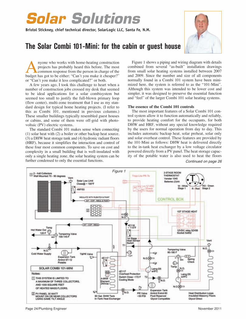
Figure 1 shows a piping and wiring diagram with detailscombined from several “as-built” installation drawingsfrom small solar heating systems installed between 2007and 2009. Since the number and size of all componentsnormally found in a Combi 101 system have been mini-mized here, the system is referred to as the “101-Mini”.Although this system was intended to be lower cost andsimpler, it was designed to preserve the essential functionand “feel” of the larger Combi 101 solar heating systems.
The essence of the Combi 101 controls
The most important features of a Solar Combi 101 con-trol system allow it to function automatically and reliably,to provide heating comfort for the occupants, for bothDHW and HRF, without any special knowledge requiredby the users for normal operation from day to day. Thisincludes automatic backup heat, solar preheat, solar onlyand solar overheat control. These features are provided bythe 101-Mini as follows: DHW heat is delivered directlyto the in-tank heat exchanger by a low voltage circulatorpowered directly from a PV panel. The heat storage capac-ity of the potable water is also used to heat the floors
Continued on page 26
The Solar Combi 101-Mini: for the cabin or guest house
Figure 1
pe11_pgs_24_27rev_Layout 1 10/27/11 10:08 AM Page 24

Any Application. Any Environment.™BASYS™
Indication is the fi rst step to diagnosis.For over two years, we conducted fi eld research and talked to plumbers, architects and engineers to develop real innovations for the people who service our products. The result is BASYS – a modular line of electronic sensor faucets that make ease-of-service a top priority. Multiple individual external indicators. One-tool entry. Above deck access. One-twist water shut off. Interchangable componentry. Backed by a century of Sloan experience, Basys meets the demands of commercial plumbing industry and the people who use our products.
I NT R O D U C I N G
©20
11 S
loan
Val
ve, I
nc. A
ll rig
hts
rese
rved
.
Build your Basys online: sloanvalve.com/basys
Circle 17 on Reader Reply Form on page 54
pe11_pgs_24_27rev_Layout 1 10/27/11 10:08 AM Page 25

through the in-tank heat exchanger. Solar domestic hot water tank control (DHW) features
include:• Low-limit aqua stat (AQ), comes with the electric ele-
ment in the hot water tank• Solar heat storage ON, PV-powered circulator runs
when sun is up• Solar heat storage OFF, PV-powered circulator stops
when sun is down• High-limit, provided by thermal switch 4E117• Safety high-limit, P & T relief valve on the DHW tank
in Fig. 40-1The heat storage capacity of masonry warm floors is
used for solar heat storage, controlled within the humancomfort range by a two-stage room thermostat. The roomtemperature is allowed to drift upwards when “free” solarheat (Stage 1) is available. A second low voltage circula-tor is switched ON and OFF to provide HRF heat.
Solar heated warm masonry floor zone control (HRF)features include:
• Auxiliary low-limit Stage 2 heat ON (backup heat isallowed)
• Minimum comfort temperature Stage 2 heat OFF(auxiliary OFF)
• Solar heat-banking allowed — Stage 1 solar room heatON
• Maximum comfort temperature — Stage 1 solar roomheat OFF
The solar glycol circulator is used to deliver heat direct-ly to the DHW tank and the HRF space heating systemwith adjustable temperature priority, using low-limit con-trols. It is also used to cool the DHW tank by circulatingafter sunset when a high-limit temperature is reached inthe tank.
Solar collector heat control features include:• Solar collector low-limit, provided by thermal switch
4MY93• Solar HRF heat banking low-limit, provided by ther-
mal switch 4E116• Evening heat dissipation high-limit, provided by ther-
mal switch 4E117
Unique design features in the Solar Combi 101-Mini
In this design, piping and wiring are simplified andcosts are cut by eliminating components and using lowvoltage circulators. This results in unexpected opportuni-ties for both thermal and electrical efficiency. Here aresome of the highlights:
There is no separate backup boiler. The solar heat stor-age tank, DHW and backup (electric) heat are all integrat-ed into one unit.
The solar heat collection and distribution can be pow-ered from AC or DC electrical sources. The pumps andcontrols can be powered by an automotive battery duringan emergency.
Low voltage DC circulators (only two) allow low volt-age switching and wiring.
The main heat exchanger between the solar collectorsand the house is eliminated, which maximizes the solarheat transfer to the DHW and HRF loads.
The primary loop or “flow center” is not used here (to
simplify the piping). This is not recommended in systemswith more heating loads, more collectors or other addedcomplexity of any kind.
Solar heat is joined to the floor heating system usingtwo tees, shown as T1 and T2 on the diagram.
All “boiler fluid” is propylene glycol antifreeze mix-ture, even in the floor tubing.
The glycol expansion tank doubles as a small refillreservoir.
Snap disk or capillary tube thermal switches are usedfor low-limit and overheat protection. (Grainger part num-bers are shown for example.)
There are no motorized zone valves or transformers topower them.
Room thermostats are two-stage, with programmable“solar” temperature swing.
Overheat protection is provided by absorbing heat intothe DHW tank and releasing it back through the solar pan-els at night.
Some optional choices
The diagram presents the bare minimum (yet fully func-tional) Combi 101 system I would ever recommend. Thereare a number of options that can be added to this design toimprove its response and adapt to other needs of a project.Here are some of the most common:
Upsize the tubing diameters to lower the pumpingpower needed (floors and solar heat supplies).
Upsize the collector and the DHW tank to increase theheat storage for night use.
The use of integral flow check (IFC) pump bodies can besubstituted with a spring check valve at the pump outlet.
Multiple heat exchangers are available in top and bot-tom along with the electric heating element (e.g., SolarContender tanks).
Integral gas burners are available with in-tank heatexchangers. These have been used (at greater expense) inlocations where electric heat is not practical.
A two-tank DHW system (in series) can be used to sep-arate the solar heat storage from the conventional heatsource.
Upgrade the thermo-mechanical switches with elec-tronic differential and set point controls.
An anti-stratification circulator is sometimes added to thewater tank to stir the tank from top to bottom when a singleheat exchanger in the tank is located near the bottom.
There are a number of compromises made in theCombi 101-Mini system that allow lower cost andgreater simplicity at the expense of precise control andideal thermal performance. This system is presentedhere mainly to illustrate the basic piping and controlissues involved in any solar combisystem and are basedon our experience with a number of successful fieldinstallations. n
Bristol Stickney has been designing, manufacturing, repair-ing and installing solar hydronic heating systems for more than30 years. He holds a Bachelor of Science in MechanicalEngineering and is a licensed mechanical contractor in NewMexico. He is the chief technical officer for SolarLogic LLC inSanta Fe, N.M., where he is involved in development of solarheating control systems and design tools for solar heating pro-fessionals. Visit www.solarlogicllc.com for more information.
Page 26/Plumbing Engineer November 2011
The views and opinions expressed in this column are those of the author anddo not reflect those of Plumbing Engineer nor its publisher, TMB Publishing.
Solar SolutionsContinued from page 24
pe11_pgs_24_27rev_Layout 1 10/27/11 10:08 AM Page 26

Circle 18 on Reader Reply Form on page 54
pe11_pgs_24_27rev_Layout 1 10/27/11 10:08 AM Page 27
Page 28/Plumbing Engineer November 2011
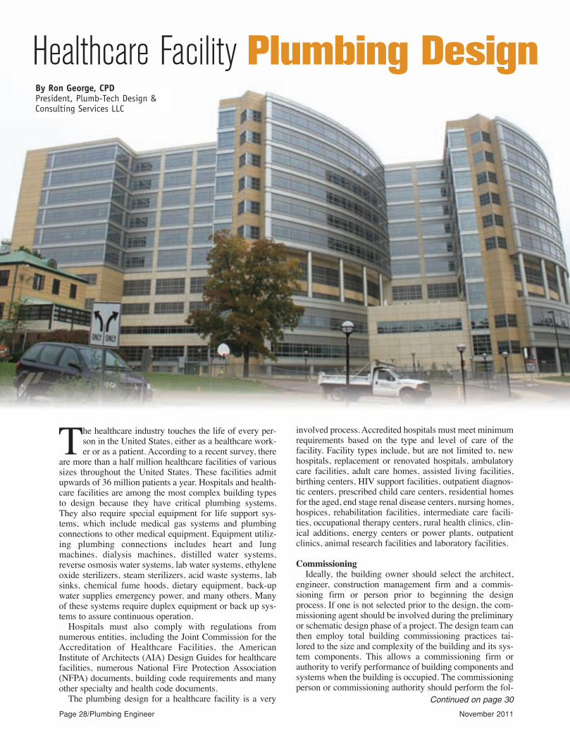
The healthcare industry touches the life of every per-son in the United States, either as a healthcare work-er or as a patient. According to a recent survey, there
are more than a half million healthcare facilities of varioussizes throughout the United States. These facilities admitupwards of 36 million patients a year. Hospitals and health-care facilities are among the most complex building typesto design because they have critical plumbing systems.They also require special equipment for life support sys-tems, which include medical gas systems and plumbingconnections to other medical equipment. Equipment utiliz-ing plumbing connections includes heart and lungmachines, dialysis machines, distilled water systems,reverse osmosis water systems, lab water systems, ethyleneoxide sterilizers, steam sterilizers, acid waste systems, labsinks, chemical fume hoods, dietary equipment, back-upwater supplies emergency power, and many others. Manyof these systems require duplex equipment or back up sys-tems to assure continuous operation.
Hospitals must also comply with regulations fromnumerous entities, including the Joint Commission for theAccreditation of Healthcare Facilities, the AmericanInstitute of Architects (AIA) Design Guides for healthcarefacilities, numerous National Fire Protection Association(NFPA) documents, building code requirements and manyother specialty and health code documents.
The plumbing design for a healthcare facility is a very
involved process. Accredited hospitals must meet minimumrequirements based on the type and level of care of thefacility. Facility types include, but are not limited to, newhospitals, replacement or renovated hospitals, ambulatorycare facilities, adult care homes, assisted living facilities,birthing centers, HIV support facilities, outpatient diagnos-tic centers, prescribed child care centers, residential homesfor the aged, end stage renal disease centers, nursing homes,hospices, rehabilitation facilities, intermediate care facili-ties, occupational therapy centers, rural health clinics, clin-ical additions, energy centers or power plants, outpatientclinics, animal research facilities and laboratory facilities.
Commissioning
Ideally, the building owner should select the architect,engineer, construction management firm and a commis-sioning firm or person prior to beginning the designprocess. If one is not selected prior to the design, the com-missioning agent should be involved during the preliminaryor schematic design phase of a project. The design team canthen employ total building commissioning practices tai-lored to the size and complexity of the building and its sys-tem components. This allows a commissioning firm orauthority to verify performance of building components andsystems when the building is occupied. The commissioningperson or commissioning authority should perform the fol-
Continued on page 30
By Ron George, CPDPresident, Plumb-Tech Design &Consulting Services LLC
Healthcare Facility Plumbing Design
pe11_pgs_28_37rev_Layout 1 10/27/11 10:18 AM Page 28

Circle 19 on Reader Reply Form on page 54
pe11_pgs_28_37rev_Layout 1 10/27/11 10:18 AM Page 29
lowing tasks on a healthcare facilityproject:
1. Include commissioning require-ments in construction documents.
2. Provide a commissioning plan.3. Field verify the installation and
performance of systems to be commis-sioned.
4. Provide a commissioning report
Circle 24 on Reader Reply Form on page 54
upon completion of the project.We continually improve the health-
care environment in the United Statesto the point that we have one of thebest healthcare systems in the world.Dr. Lewis Thomas was the formerhead of New York’s Sloan KetteringCancer Research Center and the
author of numerous books and articlesexplaining the advances in medicine.In the spring edition of the 1984 for-eign policy journal, Foreign Matters,he wrote:
“There is no question that ourhealth has improved in the last centu-ry. One thing seems certain: It did nothappen because of medicine or med-ical science or even the presence ofdoctors. Much of the credit should goto the plumbers and sanitary engi-neers of the Western world. The cont-amination of drinking water by humanfeces was at one time the single great-est cause of human disease and death.It remains so, even with starvation andmalaria, for the Third world countries.Typhoid fever, cholera and dysenterywere chief threats to survival in theearly years of the 19th century in NewYork City and other major east coastcities in the United States. When theplumbers and sanitary engineers haddone their work in the construction ofour cities, these diseases began tovanish. Today, cholera is unheard of inthis country, but it would surely reap-pear if we went back to the old fash-ioned ways of finding water to drink.”— Dr. Lewis Thomas
Water service entrance
The water service in a hospital iscritical and needs to be from a reliablesource. Water service entrance shouldbe from two sources or water mains. Awater quality test should be performedperiodically on the water supplied to ahealthcare facility to assure there isnot a high bacteria content in the watersupply that may warrant additionalwater treatment on site. Many connectto water mains from two differentstreets that are separated by isolationvalves and backflow preventers. Thisassures that water is available in theevent of a water main break or loss ofwater supply. If the hospital is in aremote location where dual servicelines are not an option, a water storagetank may be required in which casewater treatment will be necessary toassure that the water does not becomecontaminated.
A water quality test must be per-formed periodically to check for highbacteria content that may warrant
Continued on page 32
Page 30/Plumbing Engineer November 2011
HealthcareContinued from page 28
pe11_pgs_28_37rev_Layout 1 10/31/11 11:07 AM Page 30

PLUMBUNITION
IN OUR TRADE,
EVERYDAY IS A BUSINESS BATTLE.YOU NEED THE RIGHT WEAPONS TO WIN.
SIOUX CHIEF GETS THIS. WE KNOW THAT SUCCESS DOES NOT COME EASILY. YOU ARE NOT GIVEN JOBS. YOU
TAKE THEM. YOU ARE NOT GIVEN PROFITS. YOU MAKE THEM. OUR MISSION IS TO SUPPORT YOU WITH WEAPONS
TO WIN. WE INVENT, MANUFACTURE AND DISTRIBUTE FULL LINES OF ROUGH PLUMBING PRODUCTS TO HELP
YOU WIN BIDS, BUILD YOUR BRAND AND, OF COURSE, MAKE A PROFIT.
CONSIDER SIOUX CHIEF AS YOUR ROUGH PLUMBING ARMORY. TOGETHER, WE WILL TAKE THE FIELD.
www.siouxchief.comSupply Drainage Support
TAKE THE FIELD.Circle 20 on Reader Reply Form on page 54
pe11_pgs_28_37rev_Layout 1 10/27/11 10:18 AM Page 31
Circle 21 on Reader Reply Form on page 54
Page 32/Plumbing Engineer November 2011
additional water treatment on site. Water meters, backflowpreventers, chlorine injection pumps, ozonation equipment,copper silver ionization units, water softeners and otherwater treatment equipment should be located at the waterservice entrance, with duplex equipment where practical orwith bypass lines to assure continuous operation during ser-vicing of equipment. The designer should also provide apreliminary fixture unit count and determine a peak waterflow calculation to determine whether there is a need for abooster pumping package.
Water quality
While the different types of healthcare facilities in theinstitutional market have many needs in common, it is thehospital environment that presents the most unique plumb-ing challenges. Sanitation is a key requirement for theplumbing areas in this environment. Generally, patients inhospitals that have a suppressed immune system are moresusceptible to exposure of bacteria from patient to patientcontact by staff or from exposure to organic pathogensgrowing in the water supply. Hand wash sinks in patientrooms must have a clean supply of water for staff to washtheir hands. Water for cleaning instruments and equipmentis also an important part of sanitation. For this reason, manyhealthcare facilities are exempt from water and energy con-servation regulations. A recent study suggested that there
may be a correlation between water conservation andincreased bacteria content in the water. There was a study atJohn’s Hopkins University Hospital that indicated that therewas a high bacteria content in metering faucets as comparedto the bacteria count in non-metering faucets. The studyimplied that the hospital faucets with low-flow self meter-ing faucets had lower flow rates. The lower flow rates didnot allow enough flow to maintain the residual chlorine lev-els. The lower chlorine levels allowed the chlorine to dissi-pate over time in the branch piping to the low-flow faucets.Lower chlorine levels would allow bio-films to grow on thewalls of the branch piping increasing the number of organ-ic pathogens like Legionella. This study has caused quite astir in both the plumbing and healthcare industries and it isbeing reviewed by many in the plumbing industry includingmembers of the American Society of Plumbing Engineersto assure the research was not flawed and that the data isreliable. There will likely be additional information on thisissue with recommended actions to minimize bacterialgrowth in hospital water systems in the near future.
Plumbing utilities
In the early stages of a project, it is important for thedesign professional to work closely with the architect andstructural engineer to establish where plumbing chase wallswill need to be. Adequate space should be provided for fix-ture carriers; there needs to be enough room so that plumb-ing risers can be routed up and down efficiently in multi-story buildings. The plumbing supply and return risersshould be grouped together at one end of a plumbing chaseor shaft, as agreed with the other trades, to minimize con-flicts with walls, structural elements, ductwork, cable traysand other utilities. The storm drain should be routed in ver-tical chases whenever possible.
Medical equipment
The medical air compressors, oxygen manifolds, nitro-gen manifolds, nitrous oxide manifolds and medical vacu-um pump systems are all life support systems that are partof the medical gas system and according to NFPA Standardsneed redundancy or duplex systems to provide a back-up ora reserve supply. These systems are generally located at themechanical room, central utility plant or basement mechan-ical room. Cylinder manifolds are generally located in man-ifold storage rooms and they should meet the building codeand the NFPA standard requirements based on the size andvolume of the cylinders that are stored. When bulk liquidcylinders are used in larger hospitals for nitrogen or oxygenservice, the liquid is always boiling off and being releasedor vaporized as a gas. This process causes a constant build-up of pressure. If the demand for that particular gas is notsufficient the pressure will build and the relief valve willdischarge. The relief valve should be routed to a safe loca-tion as directed by NFPA 99. It is for this reason that bulkliquid cylinders should not be used in a reserve or stand-bysituation, because the tank will continue to vaporize the liq-uid into a gas and it would be possible for a liquid storagetank to become empty in a stand-by or reserve condition.Reserve supplies of medical gases for nitrogen, and oxygen
Continued on page 34
HealthcareContinued from page 30
pe11_pgs_28_37rev_Layout 1 10/27/11 10:18 AM Page 32

Circle 22 on Reader Reply Form on page 54
pe11_pgs_28_37rev_Layout 1 11/1/11 7:53 AM Page 33
Page 34/Plumbing Engineer November 2011
should be in gas cylinders unless special provisions aretaken to draw from both bulk storage tanks and a bank ofcylinders should still be utilized for a reserve supply. Thedesigner should review NFPA requirements for bulk oxy-gen storage on site and determine the bulk oxygen tanklocation and make sure it has appropriate clearances frombuildings if required.
Equipment schedules
Equipment schedules should be shown on the drawingsto indicate the basis of design, including each plumbingutility, (cold water, hot water, gas, electrical voltage, horse-power, amps, steam, pressure, notes, etc.) The scheduleshould also indicate the utility connection sizes, the type ofequipment, the maximum dimensions (if space is an issue),flow rates, the manufacturer and model number selectedand performance requirements. The following is a list ofcommon equipment schedules on the plumbing drawings:Plumbing fixture schedule, water filter schedule, watersoftener schedule, domestic water thermal expansion tankschedule, plumbing pump schedule, plumbing packagedbooster pump schedule, storage tank schedule, electricwater heater schedule, gas-fired water heater schedule,steam to hot water heat exchanger schedule, liquid to liq-uid heat exchanger schedule, storage tank with heatexchanger schedule, steam booster hot water heat exchang-er schedule, packaged reverse osmosis water unit schedule,deionization water packaged unit schedule, gas pressureregulator valve schedule, pressure reducing valve stationschedule, food service equipment utility demand schedule,medical equipment connection schedule, air compressorsystem schedule, vacuum pump system schedule, gas man-ifold systems.
Equipment pads
All floor-mounted equipment should be placed on con-crete housekeeping pads that are 4 to 6 inches thick. Floordrains should be located near the equipment pads so equip-ment drains can be piped to the floor drains without causingtrip hazards.
Gathering information
Obtain utility maps and drawings showing all of the adja-cent utilities. Get a flow test report from a nearby firehydrant from the water department or the fire department,showing the static and the residual or flowing water pres-sures with the flow rate shown for the residual pressure. Theflow test report should include the information required tohelp determine whether a pressure booster system isrequired, and it should allow the designer to determine whatthe approximate suction pressure will be for the fire pumpand the domestic water booster pump. The site utility planshould also include natural gas, sanitary sewer and stormwater sewer information.
Code review
Work closely with the architect to perform a review ofthe building and plumbing code requirements to determinewhich model code or state code and which year edition ofthe codes will be enforced by the authority having jurisdic-
tion (AHJ) for the project. Determine which year edition ofthe NFPA codes for medical gas systems and bulk oxygenstorage systems will be used and identify any local healthdepartment requirements that address health care facilities.Inquire about local requirements for kitchen equipment, airgaps and grease interceptors.
Ask local authorities or the local drain commission aboutany stormwater management requirements for retentionponds sizing criteria. Stormwater retention basins receivethe storm flow in a large pond and allow the stormwater todrain out through a controlled outlet to minimize flashflooding downstream.
Utility coordination with civil engineers
Coordinate the utility requirements with the civil engi-neer by obtaining the existing and finished grades on atopographical plan, as well as temporary or intermediategrades used for any construction phasing purpose. Requestthe soil boring information, including ground water levelfor determining whether sub soil and perimeter drains willbe required. The soil boring will indicate the soil type andthe possible infiltration flow rate from that type of soil.Coordinate with the project civil engineer to prepare a for-mal letter to the water and sewer utility requesting the fol-lowing information for the project files:
1. Site plan from the utility company showing all watermains adjacent to the site
2. Depth of the bury of the water mains based on thedatum taken from the site plan
3. Static and residual pressures in the water main (s)4. Proposed location of domestic meter assembly instal-
lations5. Requirements for minimum utility connection sizes for
water and sewer taps6. Requirements for pipe material requirements for water
and sewer building service lines7. Breakdown of work that will be performed by the util-
ity and any work required by the contractor on water servicelines.
8. Requirements for backflow preventers9. Minimum depth of bury acceptable for freeze protec-
tion of water mains in the jurisdiction.Coordinate water meter and backflow preventer assem-
bly requirements and locations and prepare coordinationdocuments that provide the following information to otherdesign team members.
To civil engineer: • Natural gas loads • Building service water line size and water supply fix-
ture unit totals • Building sanitary and storm sewer line size and waste
fixture unit totals To electrical engineer:• Plumbing equipment electrical requirements To the medical facility engineer: • Oxygen demand (also to gas supplier) If it is an exist-
ing hospital determine if the existing bulk supply has suffi-cient capacity)
• Medical gas and vacuum demand, If it is an addition,
Continued on page 36
HealthcareContinued from page 32
pe11_pgs_28_37rev_Layout 1 10/27/11 10:18 AM Page 34

Superior effi ciency rules the water.
Powerful, intelligent and constantly in motion, not just adapting to their surroundings, but dominating them. Like sharks, e-SV pumps are tough, effi cient and built to last. Thanks to a unique combination of new hydraulic design and higher effi ciency motor, the e-SV delivers
lower overall life-cycle costs and superior effi ciency compared to most pumps available today.
• Optimized hydraulic design results in superior boosting performance, effi ciency and NPSHr levels.
• All stainless-steel construction permits NSF certifi cation.
• Expanded line of pump sizes for wide range of applications.
• Patented i-ALERT™ monitor continuously measures vibration to support optimum performance. Available on pumps 10HP and above.
• New design eliminates need to remove motor, reducing repair time by up to 50 percent.
Now there’s more than one way to rule the water.
Find out more at Xyleminc.com/gouldswatertechnology/esv
Introducing the Goulds Water Technology
e-SV™ Series:energy effi cient, economical and easy-to-install stainless steel multi-stage pumps.
Goulds Water Technology is a brand of Xylem, whose 12,000 employees are dedicated to addressing the most complex issues in the global water market.
compared to most pumps available today.
• Optimized hydraulic design results in superior boosting performance, effi ciency and NPSHr levels.
• All stainless-steel construction permits NSF certifi cation.
• Expanded line of pump sizes for wide range of applications.
• Patented i-ALERTvibration to support optimum performance. Available on pumps 10HP and above.
Circle 23 on Reader Reply Form on page 54
pe11_pgs_28_37rev_Layout 1 10/27/11 10:19 AM Page 35
Page 36/Plumbing Engineer November 2011
determine whether existing equipment has sufficientcapacity
• Compressed air demand If it is an addition, determinewhether existing equipment has sufficient capacity.
To the architect:• Plumbing chase space/clearance requirements To the mechanical engineer: • Available water makeup line from a backflow preventer
location • Energy Management Control System (EMCS) point
data
Riser diagramsIf the drawings are in two-dimension CAD format, the
plumbing designer needs to sketch riser diagrams fordomestic cold water, hot water, and hot water return piping,medical air piping, medical gas piping, medical vacuumpiping and natural gas piping. With 3D CAD drawings in aBuilding Information Model (BIM) format, isometric riserdrawings can be created by adjusting the view for a 3Dimage of the actual piping drawings. If a one-line riser dia-gram is preferred, the designer still may need to sketch theriser using the 3D model as a guide; pipe sizes must and fix-ture unit valves should be transferred to the one-line draw-ing. Riser diagrams should include all fixtures, equipmentand rooms where plumbing fixtures and equipment arelocated.
Building Information Modeling (BIM)Building information modeling has become a necessity
on healthcare projects because of the complexity of thebuildings. Each trade draws their systems in 3D, and the 3Dfiles are merged into a 3D model using software designedto identify conflicts or collisions between the trades. Thecollisions are worked out among the trades and final dimen-sioned drawings are produced. Every contractor signs offon the drawings, agreeing to install their system at the ele-vation and locations indicated.
BIM has saved tens of millions of dollars on some largerprojects by allowing design professionals and contractors tobuild the building in a 3D virtual world prior to actuallystarting construction. This minimizes the amount of moneyspent on rework related to moving pipes or ducts to avoidinterferences when one trade installs their system early andcreates conflicts for other trades. BIM reduces the paper-work associated with requests for information (RFIs) andchange orders and the associated conflicts that, in somecases, require removal and reinstallation of some systems.
The plumbing designer also needs to prepare one-lineriser drawings or 3D images of the waste and vent stacks inthe building showing fixture unit values and pipe sizes oneach section of pipe.
Plumbing plan drawingsThe following systems should be shown on plumbing
drawings when indicated: domestic cold water, domestichot water, domestic hot water return, laboratory (pure)water, process water, make-up water, building sanitarysewer, sanitary vent/sanitary waste, acid waste and ventsystems, roof drains and roof conductors or roof drain lead-
ers, reagent water, hemodialysis water, reverse osmosiswater systems, demineralization or deionization water, nat-ural gas, medical gases (oxygen, nitrogen, nitrous oxide,carbon dioxide), medical vacuum, compressed air, dentalair, oral evacuation systems, hydro-therapy pool piping,potable water treatment, sub-soil drainage, reverse osmosisand other pure water equipment, water softeners, resintanks and brine tanks, equipment pads and seismic restraintsystems. This list does not include all of the systems thatmay be required for a healthcare facility project.
Pipe routing over critical areasPlumbing over operating rooms; food preparation, serv-
ing and storage areas; and electrical rooms containing maindistribution panels or motor control centers should beavoided where possible. Supply piping over such areasshould only be made only after discussions with the archi-tect and approval from the medical facility engineers. Whenpiping is necessary in these areas, provide drain pans underthe piping with tie rods on all drains in ceilings over criticalareas. Indicate leakage protection or detection systems onthe drawings or in the specifications and provide indirectdrains from the drain pans to a visible area.
Floor penetration fire-stopping/waterproofingPlumbing risers or stacks penetrating a floor above grade
(not floor drains) should have sleeves that extend 3 inchesabove the floor and 1 inch below the floor and include abuilt-in water stop and appropriate seal. All penetrationsshould be protected according to the latest edition of thebuilding code. This is to prevent a water leak on an upperfloor from pouring down to the floors below through thevoid space between the pipe and the slab. Fire-stoppingmaterial, in accordance with ASTM E-119 and/or ASTM E-814, should also be used for pipes penetrating fire wall orfloors to prevent fire from migrating upward through abuilding when pipes pass through elevated floor slabs.
Hospital equipment plumbing connectionsThere is generally a medical equipment planner for a
large hospital project. The healthcare medical equipmentplanner provides manufacturer cut sheets for the equipmentthat will be used in the hospital. The manufacturer’s datasheets typically give the manufacturer and model numberfor the piece of equipment along with an equipment num-ber that corresponds to an equipment plan. The manufac-turer’s data sheets also give the utility requirements and thecapacities. The medical equipment manufacturer plannergenerally provides equipment drawings and an equipmentschedule along with an equipment book showing the equip-ment selected for the project.
Next month, part 2 of this article will start with the med-ical equipment items that are commonly found in healthcareprojects. n
Ron George is president of Plumb-Tech Design andConsulting Services LLC. He has served as chairman of theInternational Residential Plumbing & Mechanical CodeCommittee. Visit www.Plumb-TechLLC.com, [email protected] or phone 734/755-1908.
HealthcareContinued from page 34
pe11_pgs_28_37rev_Layout 1 10/27/11 10:19 AM Page 36

Circle 24 on Reader Reply Form on page 54
pe11_pgs_28_37rev_Layout 1 10/27/11 10:19 AM Page 37
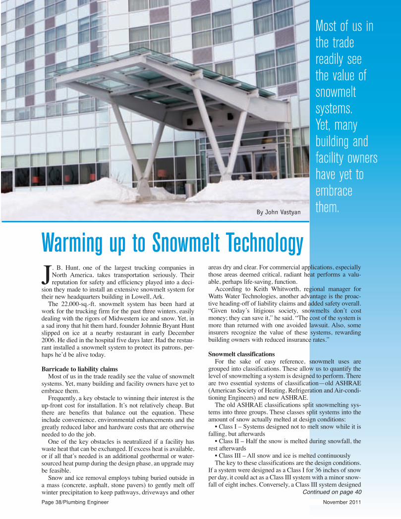
Page 38/Plumbing Engineer November 2011
J. B. Hunt, one of the largest trucking companies inNorth America, takes transportation seriously. Theirreputation for safety and efficiency played into a deci-
sion they made to install an extensive snowmelt system fortheir new headquarters building in Lowell, Ark.
The 22,000-sq.-ft. snowmelt system has been hard atwork for the trucking firm for the past three winters, easilydealing with the rigors of Midwestern ice and snow. Yet, ina sad irony that hit them hard, founder Johnnie Bryant Huntslipped on ice at a nearby restaurant in early December2006. He died in the hospital five days later. Had the restau-rant installed a snowmelt system to protect its patrons, per-haps he’d be alive today.
Barricade to liability claims
Most of us in the trade readily see the value of snowmeltsystems. Yet, many building and facility owners have yet toembrace them.
Frequently, a key obstacle to winning their interest is theup-front cost for installation. It’s not relatively cheap. Butthere are benefits that balance out the equation. Theseinclude convenience, environmental enhancements and thegreatly reduced labor and hardware costs that are otherwiseneeded to do the job.
One of the key obstacles is neutralized if a facility haswaste heat that can be exchanged. If excess heat is available,or if all that’s needed is an additional geothermal or water-sourced heat pump during the design phase, an upgrade maybe feasible.
Snow and ice removal employs tubing buried outside ina mass (concrete, asphalt, stone pavers) to gently melt offwinter precipitation to keep pathways, driveways and other
areas dry and clear. For commercial applications, especiallythose areas deemed critical, radiant heat performs a valu-able, perhaps life-saving, function.
According to Keith Whitworth, regional manager forWatts Water Technologies, another advantage is the proac-tive heading-off of liability claims and added safety overall.“Given today’s litigious society, snowmelts don’t costmoney; they can save it,” he said. “The cost of the system ismore than returned with one avoided lawsuit. Also, someinsurers recognize the value of these systems, rewardingbuilding owners with reduced insurance rates.”
Snowmelt classifications
For the sake of easy reference, snowmelt uses aregrouped into classifications. These allow us to quantify thelevel of snowmelting a system is designed to perform. Thereare two essential systems of classification—old ASHRAE(American Society of Heating, Refrigeration and Air-condi-tioning Engineers) and new ASHRAE.
The old ASHRAE classifications split snowmelting sys-tems into three groups. These classes split systems into theamount of snow actually melted at design conditions:
• Class I – Systems designed not to melt snow while it isfalling, but afterwards
• Class II – Half the snow is melted during snowfall, therest afterwards
• Class III – All snow and ice is melted continuouslyThe key to these classifications are the design conditions.
If a system were designed as a Class I for 36 inches of snowper day, it could act as a Class III system with a minor snow-fall of eight inches. Conversely, a Class III system designed
Continued on page 40
Warming up to Snowmelt Technology
Most of us inthe trade readily see the value ofsnowmelt systems. Yet, manybuilding andfacility ownershave yet to embrace them. By John Vastyan
pe11_pgs_38_43rev_Layout 1 10/27/11 10:46 AM Page 38

Engineered for quality and durability, the Woodford RHY2-MS is perfect for washing down cooling towers, cleaning condenser coils or providing water for window washers and other types of roof equipment. The hydrant support allows for installation flexibility, while its unique mounting system secures above and below the roof deck, providing exceptional strength and security. It also comes with a 2-degree shim for pitch adjustment. Featuring ASSE 1052 backflow prevention and Woodford’s freezeless technology, the RHY2-MS makes getting water on the roof easier than ever before.
For more information, visit WoodfordMfg.com.
The choice of professionals.
Think of it as a 50-story hose.Get a convenient and reliable rooftop water source when you specify the Woodford RHY2-MS roof hydrant.
naytilauqrgniloocnwsrehsawwnirofswoaevobas
oo
e
2YHRdrofdooWeht,yy,tilibaruddnocresnednocgninaelc,srewotgmpiuqefoorfosepytrehtodnasnustielihw,ytilibixeflnoitallatsnvorpkcedfoorehtwolebdna
S M-2r oslio. tneme uqing nidiv
aevobasI.yy.tirucesSAgnirutaht,y,golonh
.erofe
siv,noit
e
ecb
a
vorp,kcedfoorehtwolebdnaeerged-2ahtiwsemocoslatnoitneverpwoflkcab2501ESSetawgnittegsekamSM-2YHReh
. moc.gfMdrofdooWWotis
g nidivm ihsd nan ore
The choice of professionals.
The choice of professionals.
Circle 26 on Reader Reply Form on page 54
pe11_pgs_38_43rev_Layout 1 10/27/11 10:46 AM Page 39
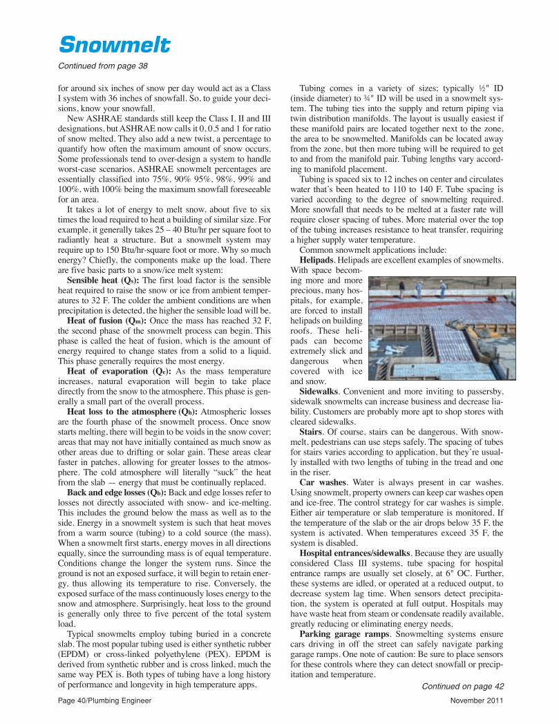
Page 40/Plumbing Engineer November 2011
for around six inches of snow per day would act as a ClassI system with 36 inches of snowfall. So, to guide your deci-sions, know your snowfall.
New ASHRAE standards still keep the Class I, II and IIIdesignations, but ASHRAE now calls it 0, 0.5 and 1 for ratioof snow melted. They also add a new twist, a percentage toquantify how often the maximum amount of snow occurs.Some professionals tend to over-design a system to handleworst-case scenarios. ASHRAE snowmelt percentages areessentially classified into 75%, 90% 95%, 98%, 99% and100%, with 100% being the maximum snowfall foreseeablefor an area.
It takes a lot of energy to melt snow, about five to sixtimes the load required to heat a building of similar size. Forexample, it generally takes 25 – 40 Btu/hr per square foot toradiantly heat a structure. But a snowmelt system mayrequire up to 150 Btu/hr-square foot or more. Why so muchenergy? Chiefly, the components make up the load. Thereare five basic parts to a snow/ice melt system:
Sensible heat (Qs): The first load factor is the sensibleheat required to raise the snow or ice from ambient temper-atures to 32 F. The colder the ambient conditions are whenprecipitation is detected, the higher the sensible load will be.
Heat of fusion (Qm): Once the mass has reached 32 F,the second phase of the snowmelt process can begin. Thisphase is called the heat of fusion, which is the amount ofenergy required to change states from a solid to a liquid.This phase generally requires the most energy.
Heat of evaporation (Qe): As the mass temperatureincreases, natural evaporation will begin to take placedirectly from the snow to the atmosphere. This phase is gen-erally a small part of the overall process.
Heat loss to the atmosphere (Qh): Atmospheric lossesare the fourth phase of the snowmelt process. Once snowstarts melting, there will begin to be voids in the snow cover;areas that may not have initially contained as much snow asother areas due to drifting or solar gain. These areas clearfaster in patches, allowing for greater losses to the atmos-phere. The cold atmosphere will literally “suck” the heatfrom the slab — energy that must be continually replaced.
Back and edge losses (Qb): Back and edge losses refer tolosses not directly associated with snow- and ice-melting.This includes the ground below the mass as well as to theside. Energy in a snowmelt system is such that heat movesfrom a warm source (tubing) to a cold source (the mass).When a snowmelt first starts, energy moves in all directionsequally, since the surrounding mass is of equal temperature.Conditions change the longer the system runs. Since theground is not an exposed surface, it will begin to retain ener-gy, thus allowing its temperature to rise. Conversely, theexposed surface of the mass continuously loses energy to thesnow and atmosphere. Surprisingly, heat loss to the groundis generally only three to five percent of the total systemload.
Typical snowmelts employ tubing buried in a concreteslab. The most popular tubing used is either synthetic rubber(EPDM) or cross-linked polyethylene (PEX). EPDM isderived from synthetic rubber and is cross linked, much thesame way PEX is. Both types of tubing have a long historyof performance and longevity in high temperature apps.
Tubing comes in a variety of sizes; typically ½" ID(inside diameter) to ¾" ID will be used in a snowmelt sys-tem. The tubing ties into the supply and return piping viatwin distribution manifolds. The layout is usually easiest ifthese manifold pairs are located together next to the zone,the area to be snowmelted. Manifolds can be located awayfrom the zone, but then more tubing will be required to getto and from the manifold pair. Tubing lengths vary accord-ing to manifold placement.
Tubing is spaced six to 12 inches on center and circulateswater that’s been heated to 110 to 140 F. Tube spacing isvaried according to the degree of snowmelting required.More snowfall that needs to be melted at a faster rate willrequire closer spacing of tubes. More material over the topof the tubing increases resistance to heat transfer, requiringa higher supply water temperature.
Common snowmelt applications include:Helipads. Helipads are excellent examples of snowmelts.
With space becom-ing more and moreprecious, many hos-pitals, for example,are forced to installhelipads on buildingroofs. These heli-pads can becomeextremely slick anddangerous whencovered with iceand snow.
Sidewalks. Convenient and more inviting to passersby,sidewalk snowmelts can increase business and decrease lia-bility. Customers are probably more apt to shop stores withcleared sidewalks.
Stairs. Of course, stairs can be dangerous. With snow-melt, pedestrians can use steps safely. The spacing of tubesfor stairs varies according to application, but they’re usual-ly installed with two lengths of tubing in the tread and onein the riser.
Car washes. Water is always present in car washes.Using snowmelt, property owners can keep car washes openand ice-free. The control strategy for car washes is simple.Either air temperature or slab temperature is monitored. Ifthe temperature of the slab or the air drops below 35 F, thesystem is activated. When temperatures exceed 35 F, thesystem is disabled.
Hospital entrances/sidewalks. Because they are usuallyconsidered Class III systems, tube spacing for hospitalentrance ramps are usually set closely, at 6" OC. Further,these systems are idled, or operated at a reduced output, todecrease system lag time. When sensors detect precipita-tion, the system is operated at full output. Hospitals mayhave waste heat from steam or condensate readily available,greatly reducing or eliminating energy needs.
Parking garage ramps. Snowmelting systems ensurecars driving in off the street can safely navigate parkinggarage ramps. One note of caution: Be sure to place sensorsfor these controls where they can detect snowfall or precip-itation and temperature.
Continued on page 42
SnowmeltContinued from page 38
pe11_pgs_38_43rev_Layout 1 10/27/11 10:46 AM Page 40

GREEN SUPPLYHAS OFFICIALLY CAUGHT UP WITH
GREEN DEMAND.
Charlotte Pipe now offers a variety of pipe made for green construction.
Distributes non-potablewater inside a building
The fi rst purple CPVCpipe, clearly marked
“DO NOT DRINK”
Using non-potable watercan earn LEED® points
The fi rst NSF-listed PVCSchedule 40 pipe withrecycled content
Center layer made from100% recycled PVC, virgininner and outer skins
Easy to install andmaintenance-free
Made from at least 96%recycled content
Long service life and 100%recyclable at the end of its life
Underground installations onlyrequire trench as wide as thepipe – no sidefi ll is needed
CAST IRON
Demand Charlotte Pipe for your next green project and we’ll supply you with green products you can trust.www.charlottepipe.com
Circle 27 on Reader Reply Form on page 54
pe11_pgs_38_43rev_Layout 1 10/27/11 10:46 AM Page 41
Circle 28 on Reader Reply Form on page 54
Page 42/Plumbing Engineer November 2011
Loading docks. Moving goods is important work, evenduring winter months.
Large area “hot pads.” Instead of melting an entire area,which is sometimes cost prohibitive, smaller areas wheresnow may be deposited are melted. This technique is oftenused for airport runways and large parking lots. Typically,tubing for hot pad slabs is spaced at 4" to 6" OC to accom-modate a large amount of snow. Remember, six inches ofsnow from a runway or parking lot will be collected anddeposited on the pad. It’s not uncommon to have a hot padof perhaps 30' by 30' with snow piled four to six feet high.
Hot pads are usually operated manually, activated when-ever the need arises. Twist timers can be used in place of on-off switches, so the operator doesn’t have to remember toswitch the system off.
Principles of operation
On-off operation. Some snowmelts are operated onlywhen there is ice or snow. These systems are operated in thepresence of precipitation, when the ambient temperature isbelow 35 F. While less costly to operate, these systems takelonger to melt precipitation, because they must first increasethe slab temperature.
Controls. These include sensors to detect precipitationwhen temperatures fall below 35 to 38 F. Because these con-trols are simple, their cost is relatively low.
After precipitation and temperature conditions are met,the system will operate until precipitation stops. Most con-trols will continue to operate the snowmelt for a period offour to six hours after precipitation has ended, ensuring anice-free surface.
Twist timers can also be used in parallel with thesnowmelting control to allow some manual control. If it’sknown that a winter storm is approaching, the system can bestarted several hours before its arrival to reduce system lagtime. Conversely, if snow happens to drift onto thesnowmelting surface but does not engage the precipitationsensor, the system can be started manually.
Sophisticated controls sense slab temperature, outdoortemperature and precipitation. These are more costly thanon-off controls but allow for much greater system control.They usually have settings for warm- and cold-weather shut-down and slab idle temperature. Cold weather shutdown isnecessary, because snowmelt systems cease to be effectivebelow about 0 F. We simply can’t provide enough energybelow 0 F to get the job done. This is rarely a challenge,however, because snow below 0 F contains very little water.
In order to help them respond faster, some systems areidled, or operated at a reduced output, until precipitation issensed with a temperature below 35 to 38 F, when the sys-tem is operated at full output. These systems allow for afaster response, and no snow or ice accumulates.
Operating cost. Snowmelts themselves are not thatexpensive to operate, since they’re only activated occasion-ally. The biggest cost incurred with a snowmelt system isthe up-front cost. Glycol antifreeze is required for all sys-tems, because system fluid is either dormant or could godormant for a period of time. Relatively large pumps may berequired to move slushy water-glycol mixture on initial sys-tem startup. Larger heat sources are required to deliver the100 – 300 Btu/hr-sq ft. Supply and return piping is requiredto get the energy from the boiler to the manifolds for the tub-ing buried in the slab. With all these factors, including alarger heat source, a snowmelt system can typically costbetween $6 – $12 per square foot.
• On-off systems. The cheapest systems to operate areon-off snowmelts, because they are only used five or 10times a year. As an example, a Class II system in Buffalo,N.Y. may cost about $0.21 per square foot per year. Thesame system in Chicago may cost $0.12 per square foot peryear. In Minneapolis, cost of operation might be $0.25 persquare foot per year.
• Idled systems. Idled systems cost more to operate,because they operate any time the temperature is below 38F. These typically consume up to 100 Btu/hr-sq ft whenev-er they are idling and up to 300 Btu/hr-sq ft. during fulloperation.
Whether you’re trying to eliminate snow in Lowell, Ark.— as is the case for J.B. Hunt — or warming a hospitalentrance in Nome, Alaska, a snowmelt system, could be theanswer you are seeking. n
John Vastyan owns Common Ground, a trade communi-cations firm based in Manheim, Pa. He has researched andwritten about plumbing and mechanical, HVAC, solar, geot-hermal and radiant heat systems for decades.
SnowmeltContinued from page 40
pe11_pgs_38_43rev_Layout 1 10/27/11 10:46 AM Page 42

Circle 29 on Reader Reply Form on page 54
pe11_pgs_38_43rev_Layout 1 10/27/11 12:38 PM Page 43

Page 44/Plumbing Engineer November 2011
Efficiency is a topic that is much discussed throughoutthe plumbing and heating industry and solar thermal,with its increasing relevancy in the market, is no
exception. Solar thermal, or hot water, collector efficiencyis being used in marketing campaigns, engineering analysisand other situations where the performance of two productsis compared head to head to decide which product is “bet-ter.” Without a general understanding of what these num-bers mean, one may be easily mislead into thinking oneproduct is superior when that may not be the case.
Solar thermal collector efficiency is, at its core, no dif-ferent than other efficiency numbers. It considers howmuch energy the collector can convert and transfer to afluid from the amount of available solar energy (known asinsolation). Trying to calculate, or rate, a collector’s effi-ciency is complicated, since the conditions surroundingthe collector are constantly changing. The fluid tempera-ture, air temperature, amount of sunlight available and theangle of the sunlight striking the collector all affect theefficiency of conversion.
In order to calculate the efficiency, the area to be analyzedmust first be defined. For flat plate collectors this is easy,since the total area and the area that absorbs the sun’s ener-gy are almost the same size. For evacuated tube collectorsthat have a round absorber and spaces between tubes, this
becomes a bit more difficult, since the areas are different. When evaluating a product, it is important to use an area
that represents the end goal of the analysis. For example,if roof space is tight, then using the overall, or gross area,would be wise. If a pure analysis of the collector’s effi-ciency is being completed then the absorber area may bemore appropriate. In Europe, collectors are usually ratedusing absorber or aperture area; collectors in the NorthAmerican market are rated using gross and aperture areaby the Solar Rating and Certification Corporation (SRCC).
Once a collector is certified to the SRCC OG-100 stan-dard, it is listed with an accompanying certification sheet.This is a great resource when comparing technologies,since the test conditions for each collector are more or lessthe same. On the lower portion of a rating table (section Ain the figure left, bottom) is a list of technical information;the right column lists values for Y-Intercept and Slope.These two numbers can be used to build the collector’sefficiency graph by using the following formula:
Efficiency = Y Intercept + Slope * ((Inlet Temperature -Ambient Temperature)/Insolation)
The value in parentheses is a ratio of the available sun-light and the difference in temperature between the fluidand air (ambient) during operation known as the fluid inletparameter. The closer to 0, the more “ideal” the environ-ment (a hot summer day, for example) and the higher theefficiency will be. Temperature difference between thefluid and the air is one of the most important values tokeep in mind when comparing collectors or evaluatingefficiency. For example, a solar thermal system running at180 F will have a completely different performance thanthe same system operating at 120 F due to the differencein fluid temperature. The Y Intercept from the certificationsheet will tell you the maximum efficiency a collector canachieve, while the slope will tell you how fast the effi-ciency will decrease as conditions worsen.
Efficiency values are taken during testing and representthe performance of the collector with a light source direct-ly perpendicular to the collector (i.e. midday). It does not,however, take into consideration the changes in geometry,which, throughout the day, month and year, affect howefficiently a collector performs.
Continued on page 46
Section A
S
Section C
I
CnoictSe
By Eric Skiba
Understanding SolarCollector Efficiency
pe11_pgs_44_47rev_Layout 1 10/27/11 12:36 PM Page 44

“We will definitely use LoadMatch again.” – Tom Baker, P.E., President
Hurst-Rosche Engineers
®
For e� ciency, LoadMatch®is the logical choice.When Tom Baker and his team at Hurst-Rosche Engineers were called in to design the mechanical systems at the new Waterloo, IL High School, the challenge was twofold: the heat-ing/cooling solution had to comply with a new state energy conserva-tion code and it had to provide built-in redundancy with exibility to accommodate a geothermal option down the road. Tom went with a Taco LoadMatch® single pipe heat pump-based system and a complete BAS energy management system supplied by Johnson Controls.
Designed with HSS software.Hurst-Rosche engineers utilized the Taco Hydronic System Solutions® software to design and equip the heating and cooling system. “HSS is a great time-saver,” says Tom. “It al-lowed us to check and then guaran-tee our design with Taco, and to link with associated disciplines working on the project.”
Easy installation. The installing contractor was equally as enthusiastic about LoadMatch®. “One pipe really helps in terms of in-stallation time. The system operates awlessly; control and maintenance
are a breeze”, said Marcus Frederick of Custom Mechanical, LLC.
See more onlineThis is just one of many LoadMatch® success stories. Visit us on line to learn how others have saved time, materials, and energy with a Taco LoadMatch® system.
www.taco-hvac.com/loadmatch
Circle 30 on Reader Reply Form on page 54
pe11_pgs_44_47rev_Layout 1 10/27/11 12:36 PM Page 45
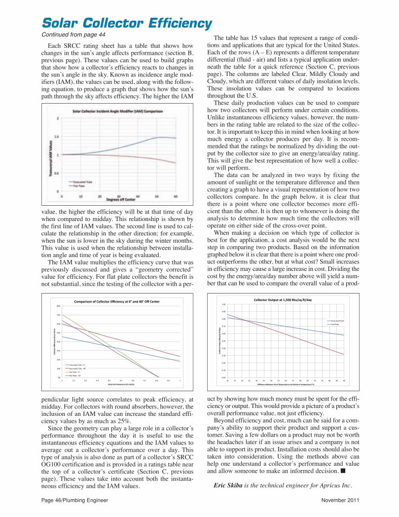
Page 46/Plumbing Engineer November 2011
Each SRCC rating sheet has a table that shows howchanges in the sun’s angle affects performance (section B,previous page). These values can be used to build graphsthat show how a collector’s efficiency reacts to changes inthe sun’s angle in the sky. Known as incidence angle mod-ifiers (IAM), the values can be used, along with the follow-ing equation, to produce a graph that shows how the sun’spath through the sky affects efficiency. The higher the IAM
value, the higher the efficiency will be at that time of daywhen compared to midday. This relationship is shown bythe first line of IAM values. The second line is used to cal-culate the relationship in the other direction; for example,when the sun is lower in the sky during the winter months.This value is used when the relationship between installa-tion angle and time of year is being evaluated.
The IAM value multiplies the efficiency curve that waspreviously discussed and gives a “geometry corrected”value for efficiency. For flat plate collectors the benefit isnot substantial, since the testing of the collector with a per-
pendicular light source correlates to peak efficiency, atmidday. For collectors with round absorbers, however, theinclusion of an IAM value can increase the standard effi-ciency values by as much as 25%.
Since the geometry can play a large role in a collector’sperformance throughout the day it is useful to use theinstantaneous efficiency equations and the IAM values toaverage out a collector’s performance over a day. Thistype of analysis is also done as part of a collector’s SRCCOG100 certification and is provided in a ratings table nearthe top of a collector’s certificate (Section C, previouspage). These values take into account both the instanta-neous efficiency and the IAM values.
The table has 15 values that represent a range of condi-tions and applications that are typical for the United States.Each of the rows (A – E) represents a different temperaturedifferential (fluid - air) and lists a typical application under-neath the table for a quick reference (Section C, previouspage). The columns are labeled Clear, Mildly Cloudy andCloudy, which are different values of daily insolation levels.These insolation values can be compared to locationsthroughout the U.S.
These daily production values can be used to comparehow two collectors will perform under certain conditions.Unlike instantaneous efficiency values, however, the num-bers in the rating table are related to the size of the collec-tor. It is important to keep this in mind when looking at howmuch energy a collector produces per day. It is recom-mended that the ratings be normalized by dividing the out-put by the collector size to give an energy/area/day rating.This will give the best representation of how well a collec-tor will perform.
The data can be analyzed in two ways by fixing theamount of sunlight or the temperature difference and thencreating a graph to have a visual representation of how twocollectors compare. In the graph below, it is clear thatthere is a point where one collector becomes more effi-cient than the other. It is then up to whomever is doing theanalysis to determine how much time the collectors willoperate on either side of the cross-over point.
When making a decision on which type of collector isbest for the application, a cost analysis would be the nextstep in comparing two products. Based on the informationgraphed below it is clear that there is a point where one prod-uct outperforms the other, but at what cost? Small increasesin efficiency may cause a large increase in cost. Dividing thecost by the energy/area/day number above will yield a num-ber that can be used to compare the overall value of a prod-
uct by showing how much money must be spent for the effi-ciency or output. This would provide a picture of a product’soverall performance value, not just efficiency.
Beyond efficiency and cost, much can be said for a com-pany’s ability to support their product and support a cus-tomer. Saving a few dollars on a product may not be worththe headaches later if an issue arises and a company is notable to support its product. Installation costs should also betaken into consideration. Using the methods above canhelp one understand a collector’s performance and valueand allow someone to make an informed decision. n
Eric Skiba is the technical engineer for Apricus Inc.
!"#
$!"#
%!"#
&!"#
'!"#
(!"#
)!"#
*!"#
+!"#
!# !,$# !,%# !,&# !,'# !,(# !,)# !,*# !,+# !,-# $#
!"##$%&"'()*%+$,
%-(./
'"00(1'$23(
4#5+6(7,#$&(82'29$&$'(..:+;:23</3(
!"9=2'+0",(">(!"##$%&"'()*%+$,%-(2&(?@(2,6(A?@(BC(!$,&$'(
./0120345#6274#8#!9#
./0120345#6274#8#'!9#
:;03#<;034#8#!9#
:;03#<;034#8#'!9#!"!!#
!"$!#
!"%!#
!"&!#
!"'!#
!"(!#
!")!#
!"*!#
!"+!#
!",!#
$"!!#
$!# $(# %!# %(# &!# &(# '!# '(# (!# ((# )!# )(# *!# *(# +!# +(# ,!#
!"##$%&"'()*&+*
&(,-&*./012.3456(
789$'$:%$(-$&;$$:(<#*83(=$>+$'4&*'$(4:3(?>@8$:&(=$>+$'4&*'$(,A<6(
!"##$%&"'()*&+*&(4&(BCDEE(-&*./012.345(
-./01/234#5163#
78/2#98/23#
Solar Collector EfficiencyContinued from page 44
pe11_pgs_44_47rev_Layout 1 10/27/11 12:36 PM Page 46

Dynamic duo simplifies valve specification – increases valve system performance.
FEATURING – PowerStation TM Water Tempering and Recirculation Systems
Take the work out of valve specification with Powers’ new online valve configuration software. Log on today to configure our new HydroGuard® XP master mixing and hi/lo tempering valves.
Easily configure new HydroGuard® XP valve systems
Quickly go from design to 2D and 3D drawing downloads
Draft, revise, print, share and securely archive plans
New valves are ASSE 1017, ASSE 1071 listed and CSA B125 certified
Valves regulate outlet temperature at flows down to 1 gpm
Control at approach temperatures as low as 5°F
Visit www.DynamicDuoExposed.com/pe
A Watts Water Technologies Company
Finally, valve configuration online!
Circle 31 on Reader Reply Form on page 54
pe11_pgs_44_47rev_Layout 1 10/28/11 8:18 AM Page 47

Page 48/Plumbing Engineer November 2011
Operating 24 hours a day, Shari’s is a restaurantchain in the Northwest. Shari’s had a 20 GPMinterceptor installed in-the-floor in their
mechanical room. The interceptor was recessed in-the-floor and only connected to their double compartmentsink. The pre-rinse was not picked up by an interceptor.The City of Hillsboro was not happy with Shari’s dis-charge; they had them pump out the GI twice a week.With the pre-rinse sink not being hooked up to the inter-ceptor this facility was discharging a lot of grease intothe sewer system.
Shari’s had Grease+Gard™ look at their applicationto see what could be done to bring them in compliance
with the city. They were able to take the pre-rinse sinkand the double bowl sink and run the two sinks througha solids interceptor, then to the GI. They were able totake the Grease+Gard™, 8175GG and mount it on topof the grease interceptor.
Now Shari’s was able to remove the solids at thesource and remove the grease out of the GI daily. Thisallowed Shari’s to go 2 months without pumping outtheir interceptor.
grease+gard™ Retrofit Skimmer and greaseRecovery device
The Grease+Gard™ system was engineered with thecommercial plumber and food facility owner in mind. It
is easy to install and can efficiently and economicallyaccommodate most food service application operatingon a continuous basis.
The Grease+Gard™ can be configured to work withmost existing grease interceptors. It can be retrofitted onany grease interceptor, metal or plastic and can be pur-chased as a system complete with unit. TheGrease+Gard™ are available in the most common sizes.The 8165 and 8175GRDs are available in 20, 25, 35 and50 g.p.m. The 8166 and 8176, Low Type GRD’s areavailable in 20, 35, and 50 g.p.m. n
The goal aT Jay R. SmiTh mfg.Co. iS To pRovide a SoluTion and
The equipmenT to minimize your initial cost
and investment into FOG management, while maxi-
mizing the benefits you will receive from a technolo-
gy that achieves efficient and practical method for
grease removal. The Grease+Gard™ Retrofit
Skimmer and GRD are the solutions you have been
looking for in the kitchen.
Jay R. Smith Mfg. Co. continues the commitment
to provide our customers with innovative products
that are unmatched in the industry. Years of dealing
with and solving grease interception problems have
allowed us to introduce the Grease+Gard™ Retrofit
Skimmer and Grease Recovery Device (GRD).
The Grease+Gard™ system uses patent pending
technology that automatically removes fats, oils, and
grease (FOG) from any interceptor before it becomes
a problem. The main principles of the system are eas-
ily understood. The Grease+Gard™ system has a belt
and heater assembly that is controlled by a 24-hour
timer. Upon a given schedule the heater warms up the
water in the interceptor and the Agitator propeller
helps to liquefy the FOG to be extracted. The belt
assembly picks up the FOG that is skimmed into a
trough. From there it flows into a storage reservoir
attached to the side of the Grease+Gard™ Skimmer.
The FOG reservoir is then emptied as needed.
By using the Grease+Gard™ Retrofit Skimmer
(installed on an existing grease interceptor) or by
installing a Grease+Gard™ GRD you are able to
remove FOG before it gets out of the kitchen area. A
Grease+Gard™ system will protect the pipes between
the kitchen and the outside interceptor.
Jay R. Smith’s 8175GRD (grease recovery device)allowed Shari’s restaurant to remove the solids at thesource and remove the grease out of the GI daily. Thisallowed Shari’s to go two months without pumping outtheir interceptor.
Grease Recovery Device Helps Restaurant Alleviate Discharge Problem
pe11_pgs_48_49rev_Layout 1 10/27/11 12:39 PM Page 48

Circle 32 on Reader Reply Form on page 54
pe11_pgs_48_49rev_Layout 1 10/27/11 12:39 PM Page 49

Page 50/Plumbing Engineer November 2011
Circle 33 on Reader Reply Form on page 54
Product News
Water-conserving aeratorThe ONE-TAP™ Metering Aeratoroffers a cost-effective alternative toexpensive electronic faucets. Waterflow starts with a single touch and theadjustable metering activator auto-matically stops the flow in two to 20seconds. This action reduces the riskof cross-contamination and providesup to 87% water savings over conven-tional faucets. Encore®, a division of
Component Hardware Group, Inc.
Circle 101 on Reader Reply Form on page 54
Hydrant product line and brochureNew hydrant product line and hydrantbrochure showcases the expandedoffering in a clear layout for a fasterunderstanding of the hydrant’s appli-cation. New, 22-page brochure fea-tures 16 new hydrants for institutional,commercial and light commercialmarkets. It has been redesigned withenhanced product images, clearerproduct descriptions, user-friendlyhydrant feature charts and a clean,modern look. Murdock Super Secur.
Circle 102 on Reader Reply Form on page 54
Check valve & flow regulatorThe redesigned CV-FR flow regulatingcheck valves come in compact 14 and15mm cartridges easy to insert directlyinto your application device. Availablein flow rates from 0.5 to 4 gpm, theyprovide drip tight backflow protectionand reliable pressure compensatingflow regulation from 15 to 150 psi.Selected flow rates help meet therequirements of ASME A112.18.1Mand CSA B125 (flow rate limits) andA112.18.3M (tightness in backflowconditions and endurance). Units certi-fied to ANSI/NSF 61. Neoperl.
Circle 103 on Reader Reply Form on page 54
pe11_pgs_50_51rev_Layout 1 10/27/11 12:41 PM Page 50

www.navienamerica.com 1-800-519-8794
•
•
•
•
•
•
•
•
The Ultimate in Energy E�ciency with Hi-Tech Comfort
Condensing
Condensing 98% Tankless Gas Water heater
noC
gnisned
anTTank98%g
er heataWas Gless ank
erter hea
Easy installa•
tingention and PVC vEasy installa
ended liftEx•
Optional built•
eady Link® CR•
s h ’s yndustrI•
SCH solid 3”” SCH solid PVC up t•
Easy installa•
stainless stcle utilizing dual yecended lif
em sttion syculaecir-in rOptional built
emstyascade Seady Link® C
ting - 98%ary s highest e�cienc
o 100’ SCH solid PVC up t
tingention and PVC vEasy installa
changersxeel estainless st
er tankwith bu�em
ting - 98%
s b ’s yndustrI•
ed rancdvA•
y! tanrars best w
ol - NR-10DUtrone cemoted r
ol - NR-10DU
gnisnednoC
vienamer.nawww
omica.cvienamer
ica Imervien ANa
1-800-519-8794
.ncica INR-10DU
ollertrone CemotR
1-800-519-8794Circle 34 on Reader Reply Form on page 54
pe11_pgs_50_51rev_Layout 1 10/27/11 12:41 PM Page 51

Page 52/Plumbing Engineer November 2011
PLUMB-TECH DESIGN & CONSULTING SERVICES, LLC
Plumbing, Piping, Fire Protection and hVaC system Design; foren-
sic investigations for mechanical system failures; litigation support;
code and standard consulting; technical writing and training semi-
nars; and CaD services.
3525 n. Dixie hwy., Monroe, MI 48162
Phone: (734) 755-1908
e-mail: [email protected]
Website: plumb-techllc.com
Classifieds
Est’d HVAC/Plumbing Co.So. OR/No. CA.
100 yr old co with great rep. 2010sales: $2.4M. 2011 on track to equal
2010 Owner retiring.503-620-1800
ContactSadie
Bechtold at847.564.1127to place aclassifiedad today inPlumbingEngineer!
Industry Movers
Grundfos names director
Olathe, Kan. — Grundfos Pumps promoted Greg Bretzto director of regional program management. Bretz will beresponsible for continuing to develop the strategic direc-tion for regional program management and acceleratingprogram management development across the entireGrundfos north america organization.
Elkay adds to board of directors
OaK BrOOK, Ill. — robert r. Buck has beenelected to serve on elkay’s board of directors.the addition of Buck to elkay’s board ofdirectors reaffirms the company’s continuedrole as a leader in the plumbing, cabinet anddecorative surfaces industries.
Girard Engineering announces promotions
Falls ChurCh, Va. — Girard engineering, PC, has pro-moted David schaeffer and susan sheridan to principalswith the firm.
pe11_pgs_52_56rev_Layout 1 10/27/11 12:47 PM Page 52

Circle 35 on Reader Reply Form on page------ 54
pe11_pgs_52_56rev_Layout 1 10/27/11 12:47 PM Page 53

Page 54/Plumbing Engineer November 2011
A.O. Smith......................................15
Acorn Aqua....................................30
AHR Expo.......................................53
Apollo ................................................9
Bradley Corp..................................29
Charlotte Pipe ...............................41
Chicago Faucets...........................43
Eemax.............................................21
Elkhart Products...........................33
Goulds.............................................35
Grundfos ...................................3, 49
IAPMO.............................................19
Josam.............................................13
LAARS .............................................16
Leonard ...........................................7
Liberty Pumps ...............................17
MIFAB .............................................50
Moen ...............................................12
Navien America.....................23, 51
Powers Process ............................47
Precision Plumbing Products....22
PVI ...................................................32
QAI...................................................42
Rheem...............................................5
Sioux Chief ....................................31
Sloan ...............................................25
Speakman Company....................37
Taco.................................................45
Viega................................................27
Watts........................................10, 11
Webstone ......................................IFC
Weil McLain.................................IBC
Woodford........................................39
Zurn.................................Back Cover
Advertiser Index
November2011
Please fill out this Reader
Reply form andfax it to us at630.739.9700 to receive the information youhave requested.
Please circle the number that corresponds to the information you’ re interested in.
1 2 3 4 5 6 7 8 9 10 11 12 13 14 15 16 1718 19 20 21 22 23 24 25 26 27 28 29 30 31 3233 34 35 36 37 38 39 40 41 42 43 44 45 46 4748 49 50 51 52 53 54 55 56 57 58 59 60 61 6263 64 65 66 67 68 69 70 71 72 73 74 75 76 7778 79 80 81 82 83 84 85 86 87 88 89 90 91 9293 94 95 96 97 98 99 100 101 102 103 104 105106 107 108 109 110 111 112 113 114 115116117 118 119 120 121 122 123 124 125 126 127 128 129130 131 132 133 134 135 136 137 138 139 140 141 142143 144 145 146 147 148 149 150 151 152 153 154 155156 157 158 159 160 161 162 163 164 165 166 167 168169 170 171 172 173 174 175 176 177 178 179 180 181182 183 184 185 186 187 188 189 190 191 192 193 194195 196 197 198 199 200 201 202 203
Subscribe online atwww.plumbingengineer.com
I wish to receive (continue receiving ) Plumbing Engineer for FREE
c Yes c No
I am engaged in plumbing engineering: c Yes c No
I am also engaged in the following kinds of engineering work:
c Piping (a) c HVAC (b) c Hydronics (c)
c Sprinkler/Fire Protection (d) c Plumbing (e)
I am employed by one of the following:
c Architectural/Engineer (a) c Mechanical Engineer (b) c Building Owner/Engineer
(c) c Consulting Engineer (d) c Contractor (e) c Design-Construct Engineer (f) c
Architect (g) c Manufacturer (h) c Manufacturers Rep (i) c Government (j)
c Mechanical Contracting (k) c Other (x)
My title is: c Construction Manager (c) c Engineer (e) c Owner (o) c
President (p) c Specifier/Design (s) c Vice President (v)
c Other
Do you design and specify products? c Yes c No
I belong to the following professional organizations:
c ASPE (a) c ASSE (b) c ASHRAE (c) c NSPE (d) c Other (e)
1
2
3
4
5
6
7
Name/Title
Company
Street Address Box No.
City State Zip
Telephone Fax
Signature (required)
Please fill out this form, sign and date below8
pe11_pgs_52_56rev_Layout 1 10/31/11 10:40 AM Page 54

Circle 36 on Reader Reply Form on page 54
pe11_pgs_52_56rev_Layout 1 10/28/11 8:20 AM Page 55
Paired Systems ProvideMaximum Performance
������������� ����������� ��������� �� ��������� �
���&������������������'���#� ����$�����������������
��������������������������������������"�����������!���!�
�������������������$���#� ������������$��������� ���"����
������������������������������!����$� ��������$������
�����������������������"��������������������������������
��������"������� ���������� ������� ������������������
��������������!�����"""�% �������
����������� ���������������� ���������� ����� ��������
����������� ���������� ����� ������ ������������������������������������������ ���
����������������������
Circle 37 on Reader Reply Form on page 54
pe11_pgs_52_56rev_Layout 1 10/31/11 7:58 AM Page 56