water supply plumbing ii - the free information society · water supply plumbing ii subcourse...
TRANSCRIPT

SUBCOURSE EDITION EN5111 A
WATER SUPPLY PLUMBING II

US ARMY PLUMBER MOS 51K SKILL LEVELS 1 AND 2 COURSE
WATER SUPPLY
PLUMBING II
SUBCOURSE EN5111
US Army Engineer School Fort Leonard Wood, Missouri
Eleven Credit Hours
GENERAL
The water supply subcourse, part of Plumber MOS 51K Skill Levels 1 and 2 course, is designed to teach the knowledge necessary for performing tasks related to preparing pipes and connecting and installing water pipelines. The subcourse is presented in two lessons. Each lesson corresponds to a terminal objective as indicated below.
Lesson 1: WATER SUPPLY SYSTEMS AND MATERIALS OBJECTIVE: Describe the procedures used to prepare steel, plastic, and copper pipes for joint
connections. TASK: 051-248-1002. Install steel, plastic, and copper pipe. CONDITIONS: You will be given the material in this subcourse. STANDARDS: You should be able to study the lesson resources, answer the practice exercises, and select the correct response for each examination question. To demonstrate competency of the task(s), you must achieve a minimum of 70 percent on the subcourse examination.
i

Lesson 2: ROUGH-IN WATER SUPPLIES AND LINES OBJECTIVE: Describe the procedures used to connect, install, and support a rough-in water
pipeline system. TASK: 051-248-1002, Install steel, plastic and copper pipe. CONDITIONS: You will be given the material in this subcourse. STANDARDS: You should be able to study the lesson resources, answer the practice exercises, and select the correct response for each examination question. To demonstrate competency of the task(s), you must achieve a minimum of 70 percent on the subcourse examination. ii

TABLE OF CONTENTS Page
GENERAL.................................................................................................................................................. i ADMINISTRATIVE INSTRUCTIONS ................................................................................................ iv GRADING AND CERTIFICATION INSTRUCTIONS ..................................................................... iv INTRODUCTION......................................................................................................................................v Lesson 1: WATER SUPPLY SYSTEMS AND MATERIALS ..............................................................1 Learning Event 1: Identifying Types of Piping Materials ........................................................................2 Learning Event 2: Measuring Pipes..........................................................................................................9 Learning Event 3: Preparing Piping Materials........................................................................................13 Review Exercise......................................................................................................................................27 Review Exercise Solutions .....................................................................................................................32 Lesson 2: ROUGH-IN WATER SUPPLIES AND LINES...................................................................33 Learning Event 1: Installing Stops (Valves)...........................................................................................34 Learning Event 2: Using Fittings on Pipe Runs......................................................................................39 Learning Event 3: Installing Water Line Pipe Runs ...............................................................................54 Learning Event 4: Supporting Pipeline Runs..........................................................................................61 Learning Event 5: Testing Systems for Leaks ........................................................................................65 Review Exercise......................................................................................................................................68 Review Exercise Solutions .....................................................................................................................72 EXAMINATION....................................................................................................................................E-1 STUDENT INQUIRY SHEET (Administrative) ..................................................................................................Following Examination STUDENT INQUIRY SHEET (Subcourse Content) ...........................................................................................Following Examination
iii

GRADING AND CERTIFICATION INSTRUCTIONS
INSTRUCTIONS TO THE STUDENT This subcourse has a written performance-based test which covers one task. First, work through the lessons and the practice exercises, then complete the review exercise found at the end of each lesson. The exercises are to help you to determine your understanding of the lessons. When you are ready to take the test, read all the directions and take the test. You must correctly answer 70 percent of the questions to successfully complete the subcourse. Eleven credit hours will be awarded for successful completion of this subcourse. iv

INTRODUCTION A plumber has to have the ability to join and install different kinds of pipes that can be used to complete the water supply pipe system of a building. These pipes are made of different materials, and many times they will have to be cut and their ends prepared for fitting connections to form leakproof joints. These connections are made with threaded joints, fused joints, and compression joints depending on the type of pipe. As the pipe system is installed with fittings, it must be supported with hangers and holders. Many times a plumber must cut into the building structure to place water supply pipeline runs to service all lavatories, sinks, and water closets that are to be installed. The plumber also tests the rough-in water supply pipeline system for leaks when it is completely installed.
v

Lesson 1 WATER SUPPLY SYSTEMS AND MATERIALS
OBJECTIVE At the end of this lesson, you will be able to describe the procedures for preparing steel, plastic, and copper pipes for joint connections. TASK 051-248-1002, Install steel, plastic and copper pipe. CONDITIONS: You will be given the material in this subcourse. STANDARDS: You should be able to study the lesson resources, answer the practice exercises, and select the correct response for each examination question. To demonstrate competency of the task(s), you must achieve a minimum of 70 percent on the subcourse examination. CREDIT HOURS 3. REFERENCES TM 5-551K and FM 5-51K 1/2.
1

Lesson 1/Learning Event 1 Learning Event 1: IDENTIFYING TYPES OF PIPING MATERIALS The layout or repair of a water supply system requires that pipes are measured to specific lengths and cuts and the ends prepared to form joints. Pipe lengths can be measured in several ways. The measurement has to allow for the pipe engagement into a fitting and a fitting's dimension. The various types of piping that can be used for a water supply system are listed below.
2

Lesson 1/Learning Event 1 Galvanized Steel Pipe. Use galvanized steel pipe above and below ground. This pipe comes in different lengths, and cutting may be necessary to allow threading.
Rigid Copper Tubing. Copper tubing comes in 10- and 20-foot lengths and is used only above ground. Types K, L, and M have the same outside diameter to accept fittings. The inside diameters for K, L, and M are different.
Flexible Copper Tubing. Flexible copper tubing comes in coils of 60 or 100 feet. Types of K and L can be used above and below ground. Both types have the advantage of bending with the use of a bending tool for installation.
3

Lesson 1/Learning Event 1 Rigid Plastic Pipe. Plastic pipe comes in 10- and 20-foot lengths and is used above and below ground. Type PVC is used for cold water supply lines. Type CPVC is used for cold and hot water lines and is temperature-rated up to 180 degrees.
Flexible Plastic Pipe. This comes in coils of 100 feet and is used above ground only. Type PB is used for cold and hot water lines and is temperature-rated from 180 to 200 degrees. Type PE is used only for cold water lines. Note. Check local plumbing codes to determine if the plastic pipe is authorized for installation.
4

Lesson 1/Learning Event 1 Use the following to make pipe engagements into a fitting for threaded steel pipes, rigid copper pipes, and rigid plastic pipes:
Rigid Copper. Measure the distance from the end of the fitting to the collar inside the fitting.
5

Lesson 1/Learning Event 1 Rigid Plastic. Measure the distance from the end of the fitting to the collar inside the fitting.
The fitting dimensions for steel pipes, rigid copper pipes, and rigid plastic pipes are shown below. To calculate a fitting's dimension, measure the distance from the end of the fitting to the center of the fitting.
6

Lesson 1/Learning Event 1 Learning Event 1 SELF-CHECK EXERCISE 1. Refer to the information given below. What is the pipe engagement for a 1 1/2-inch threaded steel
pipe?
2. Which letter shows the correct pipe engagement for rigid plastic pipes?
A. B.
3. Which letter shows the correct fitting dimension?
A. B.
7

Lesson 1/Learning Event 1 Learning Event 1 SELF-CHECK EXERCISE SOLUTIONS Your answers should be- 1. Five-eighth inch is the pipe engagement for a 1 1/2-inch pipe. 2. B is the correct answer. The plastic pipe must be against the collar in the fitting. 3. A is the correct answer. The fitting dimension is the distance from the end of the fitting to the
center of the fitting. If your answers are correct, GREAT. Continue on with the lesson. If not, go back and review the material. 8

Lesson 1/Learning Event 2 Learning Event 2: Measuring Pipes Use the following to determine pipe measurements with pipe engagements and fitting dimensions:
The example below shows the computation used for an end-to-center measurement.
Center-to-Center Measurement. Use the formula: length of pipe equals center-to-center measurement minus both fitting dimensions plus both pipe engagements.
9

Lesson 1/Learning Event 2 The example below shows the computation used for a center-to-center measurement.
Face-to-Face Measurement. Use the formula: length of pipe equals face-to-face measurement plus both pipe engagements.
The example below shows the computation used for a face-to-face measurement.
10

Lesson 1/Learning Event 2 Learning Event 2 SELF-CHECK EXERCISE 1. Refer to the illustration below. What is the length of a 1/2-inch pipe when you are using the
formula for center-to-center measurement?
A. 93 1/3 inches B. 94 1/2 inches C. 95 inches D. 95 3/4 inches
11

Lesson 1/Learning Event 2 SELF-CHECK EXERCISE SOLUTIONS Your answer should be B, 94 1/2 inches. To determine the answer, check the following methods: - Center-to-center measurement is 96 inches. - Subtract the two fitting dimensions, 1 1/4 inches + 1 1/4 inches = 2 1/2 inches, from 96 inches (96
inches - 2 1/2 inches = 93 1/2 inches. - Add the two pipe engagements, 1/2 inch + 1/2 inch, to 93 1/2 inches which should equal 94 1/2
inches. If your answer is correct, GREAT. Continue on with the lesson. If not, go back and review the material. 12
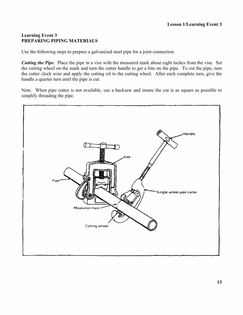
Lesson 1/Learning Event 3 Learning Event 3 PREPARING PIPING MATERIALS Use the following steps to prepare a galvanized steel pipe for a joint connection: Cutting the Pipe. Place the pipe in a vise with the measured mark about eight inches from the vise. Set the cutting wheel on the mark and turn the cutter handle to get a bite on the pipe. To cut the pipe, turn the cutter clock wise and apply the cutting oil to the cutting wheel. After each complete turn, give the handle a quarter turn until the pipe is cut. Note. When pipe cutter is not available, use a hacksaw and insure the cut is as square as possible to simplify threading the pipe.
13

Lesson 1/Learning Event 3 USING A PIPE CUTTER Removing Burrs. Push the reamer into the pipe and apply pressure with one hand. With the other hand, turn the reamer clockwise using short even strokes until all the burrs are removed from the cut end. Use a fine metal file to remove burrs from the outside of the pipe.
Threading Pipe Ends. Insert the correct size die into the die stock. Slide the die stock over the pipe and apply pressure with one hand. With the other hand, turn the stock handle slowly clockwise until the die has taken a bite on the pipe. Apply cutting oil to the die as the stock handle is given one complete clockwise turn and backed off a quarter turn. Repeat this action until 1/4 inch of the pipe is beyond the die stock. The pipe is now threaded properly. Turn the handle in a counterclockwise direction to remove the pipe.
14

Lesson 1/Learning Event 3 SELF-CHECK EXERCISE Fill in the blanks with your answers. 1. A galvanized steel pipe can be cut with a __________ and a __________. 2. Remove burrs from the inside ends of a galvanized pipe with a __________. 3. When threading a galvanized pipe, back off the stock handle __________turn after each complete
turn around the pipe.
15

Lesson 1/Learning Event 3 SELF-CHECK EXERCISE SOLUTIONS Your answers should be- 1. Pipe cutter and a hacksaw 2. Reamer 3. One-quarter turn If your answers are correct, GREAT. Continue on with learning event 3. If not, go back and review the material. 16

Lesson 1/Learning Event 3 Use the following steps to prepare copper tubing ends for joint connections: Cutting the Pipe. Hold the tubing with one hand and set the cutting wheel on the mark. Turn the knob until the wheel takes a bite on the tubing. Turn the cutter clockwise around the tubing and turn the knob at the same time to cut the tubing. To make a square cut on the tubing, use a fine-tooth blade on the hacksaw and use a miter box.
17

Lesson 1/Learning Event 3 Removing the Burrs. Push the reamer blade into the tubing and turn the tubing clockwise with even strokes.
Preparing for Soldered Joints. Use emery cloth to clean the tubing's end to a bright shine. Use the same procedure to clean the inside of the fitting.
18

Lesson 1/Learning Event 3 Preparing for Swaged Joint. Slide the tool into the tubing and hold the tubing and the tool with one hand. Place the hammer in the other hand and hit the tool until the pipe end is swaged. Use a swaged joint to join two pieces of thin-walled copper tubing without using a fitting. The swaged end is the size of a regular copper fitting.
19

Lesson l/Learning Event 3 Preparing for Flared Joint. With a flaring tool, first slide a flange nut onto the tubing. Open the yoke by loosening the wing nuts; then place the tubing in the proper size hole, and tighten the nuts. Insure the tubing is level with the top of the yoke. Turn the cone down into the tubing until it fills the bevel in the hole. The tubing is now flared. Preparing with Flanging Tool. First slide the flange nut onto the tubing. Hold the tubing and flange nut in hand. Center the flanging tool in the tubing and tap it with a hammer until the flare fills the recess in the flange nut.
20

Lesson 1/Learning Event 3 SELF-CHECK EXERCISE Fill in the blanks with your answers. 1. A copper tubing can be cut with a __________ and a __________. 2. The ends of a copper tubing are cleaned to a bright shine with an __________. 3. Thin-walled copper tubing ends can be prepared for three kinds of joint connections. List them.
A. B. C.
21

Lesson 1/Learning Event 3 SELF-CHECK EXERCISE SOLUTIONS Your answers should be- 1. Tube cutter and a hacksaw 2. Emery cloth 3. A. Soldered B. Swaged C. Flared Note. The order of the answers in question 3 is not important. If your answers are correct, GREAT. Continue on with learning event 3. If not, go back and review the material. 22

Lesson 1/Learning Event 3 Preparing Joint Connections. Use the following steps to prepare rigid, plastic, and flexible pipes' ends for joint connections. Use a hacksaw in a miter box to cut the pipe.
Remove burrs from the pipe's cut ends with a knife or sandpaper
23

Lesson 1/Learning Event 3 To prepare the ends of a plastic pipe for a cemented solvent weld joint, sand the pipe ends to remove the pipe gloss. Note. CPVC plastic pipe requires a special cleaner on the pipe's ends for solvent weld joints.
24

Lesson 1/Learning Event 3 SELF-CHECK EXERCISE Fill in the blanks with your answers. 1. A plastic pipe is cut with a __________. 2. The burrs on the cut ends of a plastic pipe are removed with a __________. 3. The ends of a rigid plastic pipe are cleaned with sandpaper to remove the pipe's __________.
25

Lesson 1/Learning Event 3 SELF-CHECK EXERCISE SOLUTIONS Your answers should be- 1. Hacksaw 2. Knife 3. Gloss If your answers are correct GREAT. Continue on with the lesson. If not go back and review the material. 26
Lesson 1/Review Exercise Lesson 1 REVIEW EXERCISE Check your understanding of lesson 1 by completing this review exercise. Try to complete all of the exercise without looking back at the lesson. When you are finished, turn to the solutions at the end of the lesson and check your responses. If you missed any questions, go back and restudy that section in the lesson where the information is given. 1. List the three types of pipes used in a water system.
A. B. C.
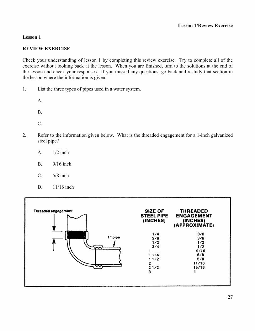
2. Refer to the information given below. What is the threaded engagement for a 1-inch galvanized
steel pipe?
A. 1/2 inch B. 9/16 inch C. 5/8 inch D. 11/16 inch
27

Lesson 1/Review Exercise 3. Which letter shows a correct fitting dimension?
4. Refer to the illustration below. What is the length of the; 1/4-inch pipe when you are using a
center-to-center measurement?
A. 48 1/4 inches B. 45 inches C. 44 1/4 inches D. 43 3/4 inches
28

Lesson 1/Review Exercise 5. Refer to the illustration below. To cut a galvanized steel pipe, you should turn the cutter handle
clockwise one-quarter turn after how many revolution(s)?
A. 2 B. 1 1/2 C. l D. 1/2
29

Lesson 1/Review Exercise 6. Refer to the illustration below. How much thread must you extend beyond the die stock to
completely thread the pipe's end?
A. 1/8 inch B. 1/4 inch C. 1/2 inch D. 5/8 inch
7. What should you use to clean a rigid copper pipe’s ends to a bright shine?
A. Wire brush B. Blitz cloth C. Emery cloth D. Waste cloth
30

Lesson 1/Review Exercise 8. What two tools should you use to flare the ends of a flexible copper tubing?
A. Swaging and flanging B. Flaring and swaging C. Flanging and flaring D. Flaring and swatting
9. What type of saw should you use to cut a rigid plastic pipe?
A. Coping saw B. Rip saw C. Crosscut saw D. Hacksaw
10. What should you use to remove the gloss on the ends of a rigid plastic pipe?
A. Emery cloth B. Steel wool C. Sandpaper D. Knife
31

Lesson 1/Review Exercise REVIEW EXERCISE SOLUTIONS 1. A. Galvanized steel (pages 3 and 4) B. Copper tubing C. Plastic Note. The order of the answers in question 1 is not important. 2. B (page 5) 3. D (page 6) 4. B (pages 9 and 10) 5. C (page 13) 6. B (page 14) 7. C (page 18) 8. C (page 20) 9. D (page 23) 10. C (page 24) 32

Lesson 2 ROUGH-IN WATER SUPPLIES AND LINES
OBJECTIVE At the end of this lesson you will be able to describe the procedures to connect, install, and support a rough-in water pipeline system. TASK 051-248-1002, Install steel, plastic and copper pipe. CONDITIONS You will be given the material in this subcourse. STANDARDS You should be able to study the lesson resources, answer the practice exercises, and select the correct response for each examination question. To demonstrate competency of the task(s), you must achieve a minimum of 70 percent on the subcourse examination. CREDIT HOURS 8. REFERENCES TM 5-551K and FM 5-51K 1/2.
33
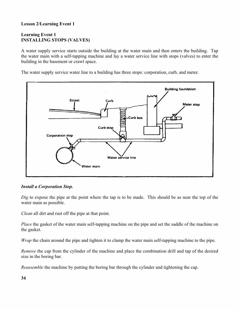
Lesson 2/Learning Event 1 Learning Event 1 INSTALLING STOPS (VALVES) A water supply service starts outside the building at the water main and then enters the building. Tap the water main with a self-tapping machine and lay a water service line with stops (valves) to enter the building in the basement or crawl space. The water supply service water line to a building has three stops: corporation, curb, and meter.
Install a Corporation Stop. Dig to expose the pipe at the point where the tap is to be made. This should be as near the top of the water main as possible. Clean all dirt and rust off the pipe at that point. Place the gasket of the water main self-tapping machine on the pipe and set the saddle of the machine on the gasket. Wrap the chain around the pipe and tighten it to clamp the water main self-tapping machine to the pipe. Remove the cap from the cylinder of the machine and place the combination drill and tap of the desired size in the boring bar. Reassemble the machine by putting the boring bar through the cylinder and tightening the cap. 34
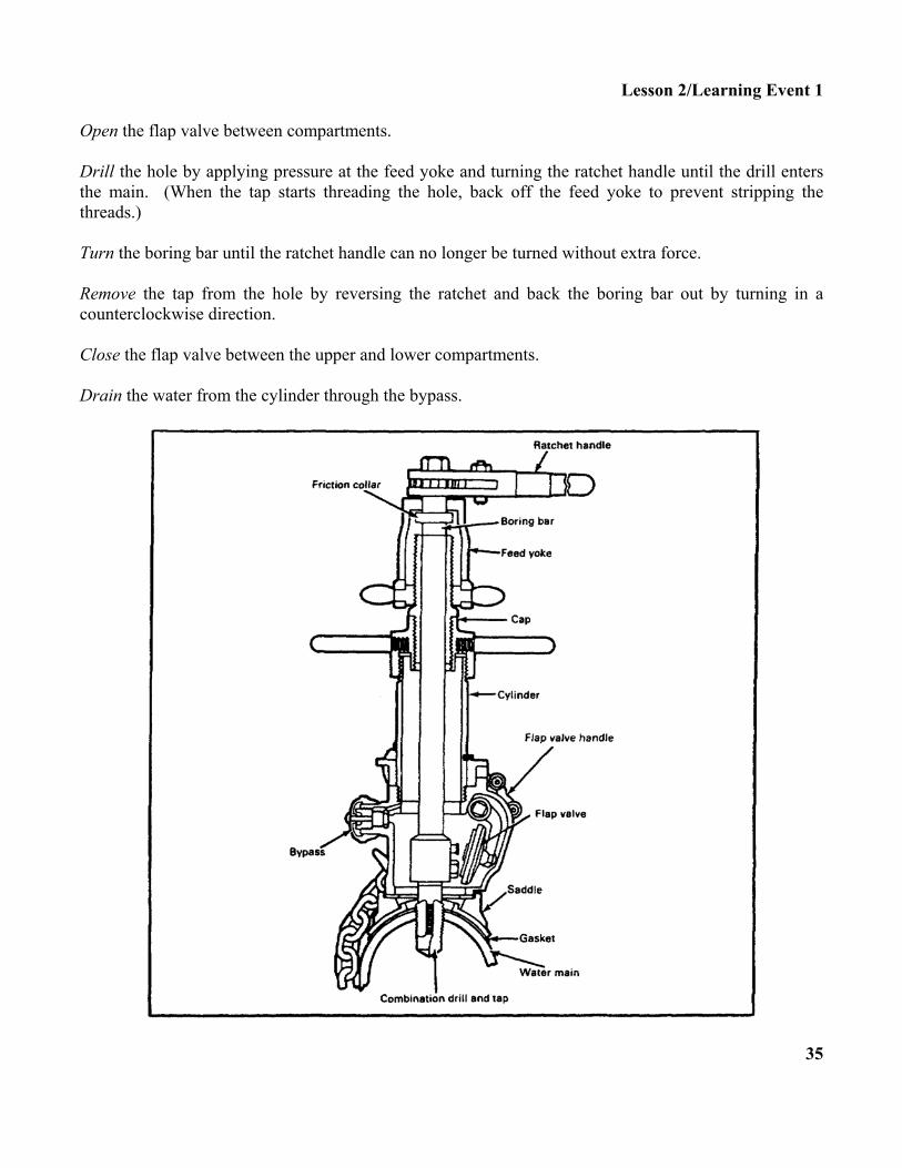
Lesson 2/Learning Event 1 Open the flap valve between compartments. Drill the hole by applying pressure at the feed yoke and turning the ratchet handle until the drill enters the main. (When the tap starts threading the hole, back off the feed yoke to prevent stripping the threads.) Turn the boring bar until the ratchet handle can no longer be turned without extra force. Remove the tap from the hole by reversing the ratchet and back the boring bar out by turning in a counterclockwise direction. Close the flap valve between the upper and lower compartments. Drain the water from the cylinder through the bypass.
35

Lesson 2/Learning Event 1 Remove the cap and drill tool, and place a corporation stop of the desired size in the boring bar. The corporation stop should be closed. Reassemble the machine by putting the boring bar through the cylinder and tightening the cap. Open the flap valve between compartments. Turn the ratchet handle to screw the corporation stop into the pipe. Drain the water from the cylinder through the bypass. Remove the cap from the cylinder and unbolt the boring bar from the corporation stop. Remove the lower chamber from the pipe. Inspect the installation for leaks. Tighten the corporation stop with a suitable wrench if it leaks. Install a Curb Stop. Position the curb stop in a suitable place between the curb and the building. Set the curb stop in a cast-iron stop box that has a variable telescopic length. Note. The curb stop provides a shutoff of water supply outside a building. Install a Meter Stop. Place the meter stop as near as possible to where the water service pipe enters the building. Position the water meter near the meter stop valve. Open the stop valve to measure the amount of water being used in the building Note. The meter stop controls the flow of water into a building.
36

Lesson 2/Learning Event 1 SELF-CHECK EXERCISE Fill in the blanks with your answers. 1. List the three types of stops that are installed between the water main and the building.
A. B. C.
2. The __________ stop shuts off or controls the amount of water flow into a building. 3. The __________ stop shuts off the water supply outside of the building.
37

Lesson 2/Learning Event 1 SELF-CHECK EXERCISE SOLUTIONS Your answer should be- 1. A. Corporation B. Curb C. Meter Note. The order of the answers in question 1 is not important 2. Meter 3. Curb If your answers are correct, GREAT. Continue on with the lesson. If not, go back and review the material. 38

Lesson 2/Learning Event 2 Learning Event 2 USING FITTINGS ON PIPE RUNS In a building, install pipe runs with fittings to join and change the direction of the water flow. The fittings-to-pipe connections must be leakproof.
39

Lesson 2/Learning Event 2 Preparing Tube Joints. Apply compound to pipe threads only. Screw the fitting clockwise by hand. Tighten with a pipe wrench (wipe off excess compound).
40

Lesson 2/Learning Event 2 SELF-CHECK EXERCISE 1. Match each galvanized pipe fitting with its name.
A. Reducer B. Union C. Tee D. Forty-five degree elbow
Fill in the blanks with your answers. 2. A galvanized pipe threaded joint connection with a fitting requires that __________ be applied
only to the __________. 3. Screw the fitting on the pipe until it is __________. 4. Tighten the fitting by using two __________.
41

Lesson 2/Learning Event 2 SELF-CHECK EXERCISE SOLUTIONS Your answers should be- 1. C, Tee D, Forty-five degree elbow A, Reducer B, Union 2. Pipe joint compound, pipe threads 3. Hand tight 4. Pipe wrenches If your answers are correct, GREAT. Continue on with learning event 2. If not, go back and review the material. 42

Lesson 2/Learning Event 2 Preparing Joints for Copper Fittings. The various types of copper tubing fittings for soldered and flared joints are shown below.
43

Lesson 2/Learning Event 2 Preparing Copper Tube Joints (Rigid). Flux completely around the outside end of the tubing and the inside end of the fitting. Place fitting on tubing. Use a quarter turn to spread the flux evenly. Heat fitting with a torch until flux bubbles. Place solder on the connection until beads form completely around the edge of the fitting. Clean the joint with a wet cool rag.
Flared Joints. Place flange nut over the cut end of tubing with threads facing the cut end; then flare the tubing at the cut end. Screw the flange nut on the fitting by hand. Tighten the screw using two wrenches, one on the fitting and one on the flange nut.
44

Lesson 2/Learning Event 2 Preparing Copper Tube Fittings (Flexible). Insure tubing is cut square. Slide compression nut and ring onto tubing. SLIDE fitting onto tubing. Hold compression nut and ring against the fitting and turn the nut clockwise until it holds. Tighten the compression joint with wrenches, using one wrench on the nut and one wrench on the fitting.
45

Lesson 2/Learning Event 2 SELF-CHECK EXERCISE 1. Match each soldered fitting with its name.
A. Male adapter B. Coupling C. Tee D. Female adapter E. Ninety-degree elbow
46
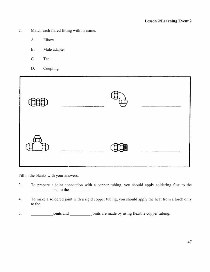
Lesson 2/Learning Event 2 2. Match each flared fitting with its name.
A. Elbow B. Male adapter C. Tee D. Coupling
Fill in the blanks with your answers. 3. To prepare a joint connection with a copper tubing, you should apply soldering flux to the
__________ and to the __________. 4. To make a soldered joint with a rigid copper tubing, you should apply the heat from a torch only
to the __________. 5. __________ joints and __________ joints are made by using flexible copper tubing.
47

Lesson 2/Learning Event 2 SELF-CHECK EXERCISE SOLUTIONS Your answers should be- 1. E, Ninety-degree elbow A, Male adapter B, Coupling C, Tee D, Female adapter 2. D, Coupling C, Tee A, Elbow B, Male adapter 3. Outside end of the pipe, inside of the fitting 4. Fitting 5. Flared, compression If your answers are correct, GREAT. Continue on with learning event 2. If not, go back and review the material. 48

Lesson 2/Learning Event 2
49

Lesson 2/Learning Event 2 Attaching Fittings to Rigid Plastic Pipes to Form Solvent Welded Joints. Swab the solvent weld cement around the outside of the pipe end. Swab the solvent weld cement to inside of the fitting. Push the fitting on the pipe using a quarter turn to spread the cement evenly. Hold the fitting firmly on the pipe for about a minute. Wipe excess cement from around fitting.
50

Lesson 2/Learning Event 2 Attaching Fittings to Flexible Plastic Pipes to Form Clamped Joints. Slide the metal clamp on the pipe. Push the pipe on the fitting as far as it can go. Move the clamps in place. Tighten with a screwdriver.
51

Lesson 2/Learning Event 2 SELF-CHECK EXERCISE 1. Match each rigid plastic pipe fitting with its name.
A. Coupling B. Ninety-degree elbow C. Female adapter
2. Match each flexible plastic pipe fitting with its name.
A. Male adapter B. Coupling C. Ninety-degree elbow
Fill in the blanks with your answers. 3. To prepare a joint connection with a rigid plastic pipe, you should apply a solvent weld cement
to the __________ and to the __________. 4. To form joint connections with flexible plastic pipe, you should use __________. 52

Lesson 2/Learning Event 2 SELF-CHECK EXERCISE SOLUTIONS Your answers should be- 1. C, Female adapter A, Coupling B, Ninety-degree elbow 2. C, Ninety-degree elbow A, Male adapter B, Coupling 3. Outside end of the pipe, inside of the fitting 4. Metal clamps If your answers are correct, GREAT. Continue on with the lesson. If not, go back and review the material.
53

Lesson 2/Learning Event 3 Learning Event 3 INSTALLING WATER LINE PIPE RUNS Install water line pipe runs during the building construction. The following steps will make it easier to rough-in pipe runs with fittings, support the pipe runs, and test the rough-in water pipe system joints for leaks. The pipe runs consist of distribution lines, branch lines, and riser lines which will service the fixtures or equipment. Main Distribution Lines. Install this pipeline, with all fittings required for the branch lines, between or through the floor joist from the meter stop. The pipe size will be the same as the water service line. Branch Lines. From the fittings on the distribution line, install the branch pipelines between or through the floor joist to those fixture points that the riser pipes will service. Fixture Riser Lines. From the branch pipeline fittings, install fixture supply pipe risers by drilling holes through the sole plate or floor. Set the risers with fittings to connect the water supply. Set the air chamber to control the pipe noise.
54

Lesson 2/Learning Event 3 SELF-CHECK EXERCISE 1. Refer to the illustration below. List the rough-in water pipelines.
A. __________ B. __________ C. __________ D. __________ E. __________ F. __________
55

Lesson 2/Learning Event 3
SELF-CHECK EXERCISE SOLUTIONS Your answers should be-
A. Cold water distribution pipeline B. Cold water branch pipeline C. Hot water riser line for fixture D. Cold water riser line for fixture E. Air chamber for pipe noise control F. Hot water distribution pipeline
If your answers are correct GREAT. Continue on with learning event 3. If not, go back and review the material. 56

Lesson 2/Learning Event 3 Install Rough-In Water Lines. Drill a hole through the center of a joist. The hole cannot be larger than one quarter of the depth of the joist. Center the hole between the top and bottom of the joist. For example, if you are using a 2- by 8-inch joist, the hole cannot be any larger than 2 inches.
Add Notches. Notches can be at the top or bottom of a joist. The notch width should be slightly larger than the outside diameter of the pipe. The notch depth can be no more than a quarter of the joist depth. Cut both sides to the proper notch depth with a handsaw. For example, if the joist depth is 8 inches and the notch depth equals 1/4 of 8 inches, the notch depth would be 2 inches. Use a hammer and a sharp wood chisel to cut away the wood between the saw cuts.
57

Lesson 2/Learning Event 3 Brace a Joist. With the notch cut up, place a 2- by 2-inch board on each side. Center the Boards. Under the notch, center boards and nail in place. When the notch is cut at the bottom, center a steel plate over the notch.
Cut a Wall Stud. Cut a notch no larger than one-third to one-half of the stud's depth. Insure the cut-out notch is able to take the pipe size to be installed. Measure the depth of a wall stud before cutting notches.
58

Lesson 2/Learning Event 3 Brace Notch Cuts. When bracing notch cuts in the wall studs with pipe runs, insure the studs with the notch cuts at the top or bottom have steel plates centered over the notches.
59

Lesson 2/Learning Event 3 SELF-CHECK EXERCISE 1. What is the largest-sized hole that can be drilled through the center of a 2- by 8-inch floor joist
for a pipe run?
A. 1 inch B. 2 inches C. 3 inches D. 4 inches
2. What is the maximum depth that a notch can be cut in a floor joist?
A. 1/4 of joist's depth B. 1/3 of joist's depth C. 1/2 of joist's depth D. 2/3 of joist's depth
3. What is the maximum depth that a notch can be cut at the bottom of a wall stud?
A. 1/4 of stud's depth B. 1/3 of stud's depth C. 1/2 of stud's depth D. 2/3 of stud's depth
Fill in the blank with your answer. 4. Brace a notch cut at the bottom of a joist or in the lower half of a wall stud with a __________. SELF-CHECK EXERCISE SOLUTIONS Your answers should be- 1. B, 2 inches is the largest hole that can be used 2. A, 1/4 of the joist's depth is the maximum 3. C, 1/2 of the stud's depth is the maximum 4. Steel plate If your responses are correct, GREAT. Continue on with the lesson. If not, go back and review the material. 60
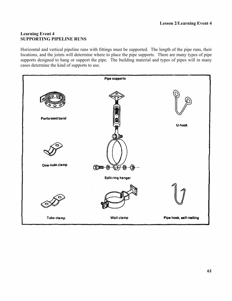
Lesson 2/Learning Event 4 Learning Event 4 SUPPORTING PIPELINE RUNS Horizontal and vertical pipeline runs with fittings must be supported. The length of the pipe runs, their locations, and the joints will determine where to place the pipe supports. There are many types of pipe supports designed to hang or support the pipe. The building material and types of pipes will in many cases determine the kind of supports to use.
61

Lesson 2/Learning Event 4 Supporting Horizontal Water Piping. Use tube clamps, U-hooks or self-nailing hooks, perforated bands, and one-hole clamps to support a horizontal pipe run to a joist.
Supporting Vertical Water Piping. Use wood blockings to attach the pipe supports. The pipe supports which can be used to support a vertical water piping run are tube clamps, one-hole clamps, and perforated bands.
62

Lesson 2/Learning Event 4 SELF-CHECK EXERCISE Fill in the blank with your answer. 1. Horizontal and vertical __________ runs must be supported. 2. Match each pipe support with its name.
A. Tube clamp
B. Self-nailing pipe hook
C. Wall clamp
D. Perforated band
E. One-hole clamp
63

Lesson 2/Learning Event 4 SELF-CHECK EXERCISE SOLUTIONS Your answers should be- 1. Pipeline 2. D. Perforated band
C. Wall clamp E. One-hole clamp A. Tube clamp B. Self-nailing pipe hook
If your responses are correct, GREAT. Continue on with the lesson. If not, go back and review the material. 64

Lesson 2/Learning Event 5 Learning Event 5 TESTING SYSTEMS FOR LEAKS Once the rough-in water pipeline system is completed, test the system for leaks. Locate and repair any leaks at once and retest the system. Test a Rough-In System. Plug and cap all openings. Open the meter stop valve to allow the WATER PRESSURE to flow into the piping. Check all fitting joints and pipes for leaks.
Resume Service. Loosen the cap and plugs one at a time to allow trapped air in the pipeline system to escape.
65

Lesson 2/Learning Event 5 SELF-CHECK EXERCISE Fill in the blanks with your answers. 1. To test a rough-in water pipeline system, you must __________ and __________ all openings. 2. Open the meter stop valve for __________ to flow into the piping. 3. Loosen plugs and caps one at a time to allow __________ in the system to escape. 66

Lesson 2/Learning Event 5 SELF-CHECK EXERCISE SOLUTION Your answers should be- 1. Plug, cap 2. Water pressure 3. Trapped air If your answers are correct, GREAT. Continue on with the lesson. If not, go back and review the material.
67

Lesson 2/Review Exercise REVIEW EXERCISE Check your understanding of lesson 2 by completing this review exercise. Try to complete all of the exercises without looking back at the lesson. When you are finished, turn to the solutions at the end of the lesson and check your answers. If you missed any questions, go back and restudy the place in the lesson where the information is given. 1. Where should you place the pipe joint compound to form a threaded galvanized steel pipe joint?
A. Fitting threads B. Cut threads C. Pipe threads D. Pipe and fitting threads
2. Where should you apply the soldering flux to form a soldered joint for a rigid copper tubing?
A. Outside of pipe and fitting end B. Outside of pipe end only C. Outside of pipe end and inside of fitting D. Inside of fitting only
3. Where does the soldering of a rigid copper tubing joint require the torch heat to be placed?
A. Pipe B. Solder C. Flux D. Fitting
4. Where should you apply the solvent cement to form a solvent weld joint for a rigid plastic pipe?
A. Inside of fitting only B. Outside of fitting and pipe C. Outside of pipe end only D. Outside of pipe end and inside of fitting
68

Lesson 2/Review Exercise 5. The water supply service water line to a building has three stops which are corporation, curb, and
meter.
A. True B. False
6. Refer to the illustration below. What are pipeline runs A, B, and C called?
A. B. C.
69

Lesson 2/Review Exercise 7. Refer to the illustration below. What is the maximum notch depth cut in a 2- by 8-inch floor
joist?
A. 4 inches B. 3 inches C. 2 inches D. 1 inch
8. Refer to the illustration below. What is the maximum notch depth cut for a stud's measured
distance?
A. 1/8 of measured distance B. 1/4 of measured distance C. 1/3 of measured distance D. 1/2 of measured distance
70

Lesson 2/Review Exercise 9. All horizontal and vertical pipeline runs must be supported.
A. True B. False
10. A rough-in pipeline water system in a building is tested for leaks before the floor and walls are
installed.
A. True B. False
71

Lesson 2/Review Exercise REVIEW EXERCISE SOLUTIONS 1. C (page 40)
2. C (page 44)
3. D (page 44)
4. D (page 50)
5. A. True (page 34)
6. A. Cold water distribution pipeline B. Cold water branch pipeline C. Cold water riser line
(See page 54 for the answers to question 6.)
7. C (page 57)
8. D (page 58)
9. A. True (page 61)
10. A. True (page 65) 72