hardware side of jt65-hf. required hardware: hf ssb transceiver computer 2-6 customs cables digital...
TRANSCRIPT

Hardware Side of JT65-HF

Required Hardware:• HF SSB Transceiver• Computer• 2-6 Customs Cables• Digital Interface (may not be required)

HFTransceiver
Computer DigitalInterface
JT65 Hardware Interconnects
HFTransceiver
Computer
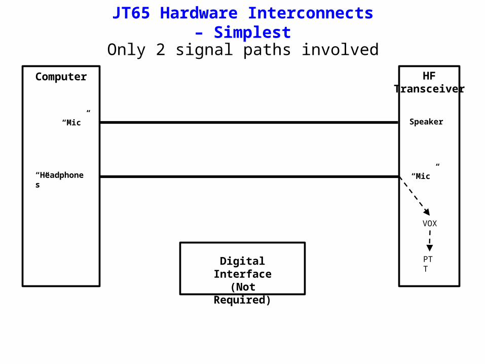
“Mic”
“Headphones”
Speaker
“Mic”
JT65 Hardware Interconnects – Simplest
Digital Interface(Not Required)
VOX
PTT
Only 2 signal paths involved

HFTransceiver
Computer
“Mic”
“Headphones”
Serial Port
Speaker
“Mic”
JT65 Hardware Interconnects – Simple
5 PTT Gnd
7 PTT
Digital InterfacePTT Gnd
PTT
9 Pin RS 232Connectors
Only 3 signal paths involved
Only required to generate PTT signal
RTS
GND

Digital Interface - Simplest
5 PTT Gnd
7 PTT2.2 K
9 Pin RS 232Connector
PTT Gnd
PTT
NPNtransistor
Diodes = any working diode

POTENTIAL PROBLEMS:• Some computers do not have a “MIC” input• Tones generated by computer may not have equal amplitude
• May be hard to identify this problem• May not be a common problem
• No RS 232 serial port• Difficult to set MIC level to transmitter
• Typical computer audio out is ~2V• Typical “MIC” input level is ~10mV
• Difficult to set MIC level to computer• Don’t use JT65 software to adjust receiver audio level
• Ground loops

HFTransceiver
Computer
“Mic”
“Headphones”
Speaker
“Mic”
Digital Interface
USB 2.0 to RS232 Converter•Mfg: eforcity•Model: PCABUSBX0049•Driver Download: http://driverdownload168.com
9 Pin RS 232Connectors
FM“USB” Port
Digital Interconnects Using A USB Port
PTT Gnd
PTT

HFTransceiver
Computer DigitalInterface
FM
“Mic”
“Headphones”
“USB” Port
F M
F MReceiver
AudioOut
FM
“Mic”F M
Digital Interconnects – Best

Ground Loops
HFTransceiver
Computer
120 VACOutlet
V2 mVACV1 mVAC
“Mic”Mic

Ground Loops
HFTransceiver
Computer
“Mic”Mic
V5 mVAC
V4 mVACV3 mVAC
120 VACOutlet
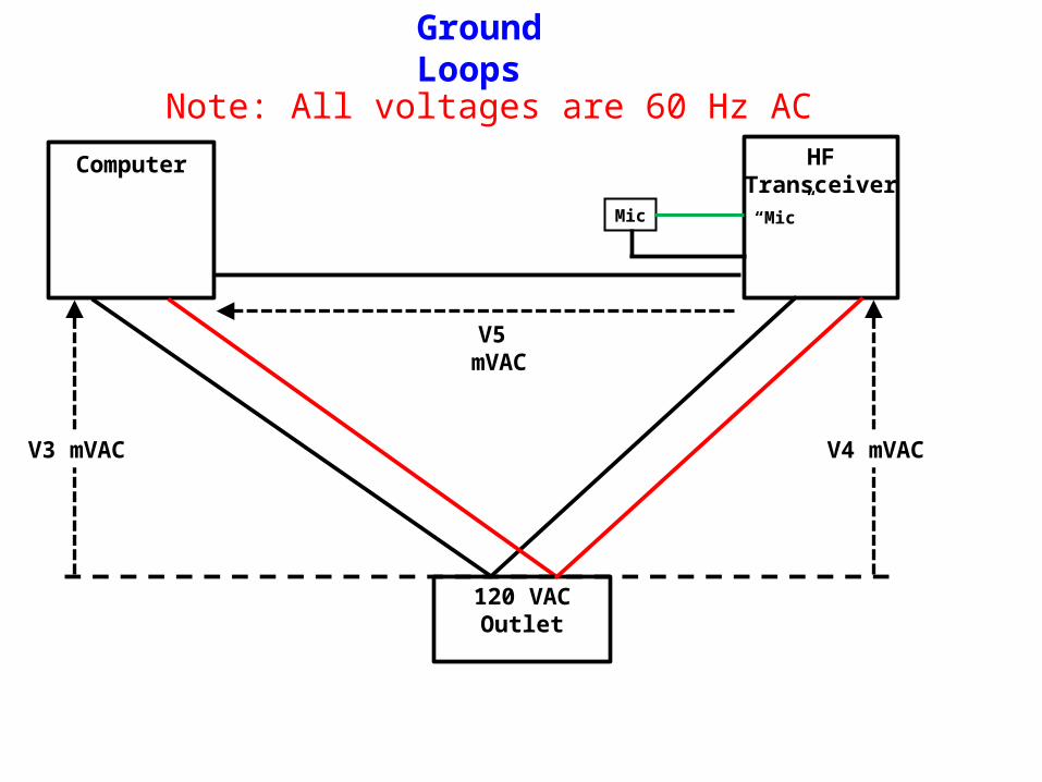
Ground Loops
HFTransceiver
Computer
“Mic”Mic
V5 mVAC
V4 mVACV3 mVAC
120 VACOutlet
Note: All voltages are 60 Hz AC
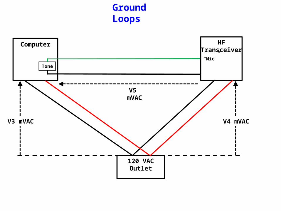
Ground Loops
HFTransceiver
Computer
“Mic”
Tone
V5 mVAC
V4 mVACV3 mVAC
120 VACOutlet

Ground Loops
HFTransceiver
“Mic”
Tone
V5
V4 mVAC
120 VACOutlet

Ground Loops
HFTransceiver
“Mic”
Tone
V5
V4 mVAC
120 VACOutlet
Note: • V5 will cause 60 Hz hum on transmit signal• V5 can also cause broadband noise on transmit signal• Typical microphone output level ~10 mV

Ground Loops
HFTransceiver
Laptop
V2 mVAC
“Mic”
0 mVAC
Tone
120 VACOutlet

Ground Loops
HFTransceiver
Computer
“Mic”
V5 = V2 – V1
Tone
X X
V2 mVACV1 mVAC
120 VACOutlet
Ground Loops
HFTransceiver
Computer
“Mic”
Tone Isolator
V2 mVACV1 mVAC
120 VACOutlet

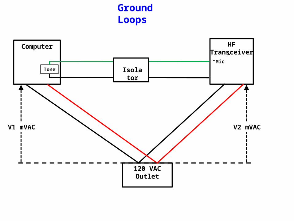
Ground Loops
HFTransceiver
Computer
“Mic”
Tone Isolator
V2 mVACV1 mVAC
120 VACOutlet
Several types of isolators: • DC signals• Audio signals• RF signals

9 PinRS 232
Connector*
5 PTT Gnd
F
7 PTT
+8 VDCfor Mic
100 uF
1 K
•Transformers are Mouser P/N 546-149T• 600W CT/600W CT• 200 Hz to 15 KHz• 1 watt
*: Not included in some (ie, SCI-6) designs
To Mic Input*
Digital Interface
IsoPTT
+10 K
50
Optocoupler4N33
FromReceiverAudio*
IsolationTransformer
IsolationTransformer
FromComputer
“Headphones”M
MTo
Computer“Mic”
From USB 2.0to RS232
Converter
1 5
42
FPTT 5
PTT GND 6
MIC GND 7
MIC 1
M
FerriteChoke*
1 K* LED*
SHLDBRN
WHT
BLU
RED
1 K*

Optocoupler
Optocoupler
1 5
42
Turn-On time <5 usecTurn-OFF time < 100 usec