acgrat101l-hf thru. acgrat105l-hf
TRANSCRIPT
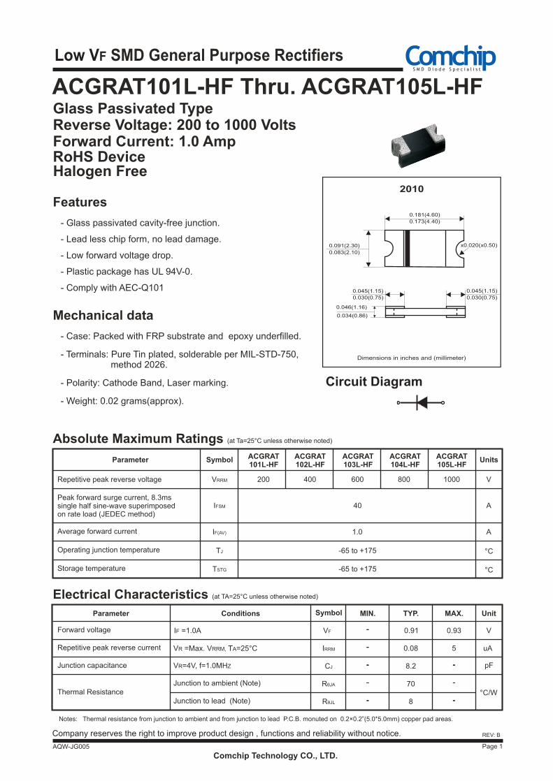
Low VF SMD General Purpose Rectifiers
Glass Passivated Type Reverse Voltage: 200 to 1000 Volts Forward Current: 1.0 Amp RoHS Device
Page 1
REV: B
Features
- Glass passivated cavity-free junction.
- Lead less chip form, no lead damage.
- Plastic package has UL 94V-0.
- Low forward voltage drop.
Mechanical data
- Case: Packed with FRP substrate and epoxy underfilled.
- Terminals: Pure Tin plated, solderable per MIL-STD-750, method 2026.
- Polarity: Cathode Band, Laser marking.
- Weight: 0.02 grams(approx).
ACGRAT101L-HF Thru. ACGRAT105L-HF
AQW-JG005
Notes: Thermal resistance from junction to ambient and from junction to lead P.C.B. monuted on 0.2×0.2”(5.0*5.0mm) copper pad areas.
Comchip Technology CO., LTD.
Absolute Maximum Ratings (at Ta=25°C unless otherwise noted)
ACGRAT101L-HF
Repetitive peak reverse voltage
Peak forward surge current, 8.3ms single half sine-wave superimposed on rate load (JEDEC method)
Average forward current
Operating junction temperature
Storage temperature
ACGRAT102L-HF
ACGRAT103L-HF
ACGRAT104L-HF
ACGRAT105L-HF
UnitsSymbolParameter
VRRM
IFSM
IF(AV)
TJ
TSTG
200 400
40
1.0
-65 to +175
-65 to +175
600 V
A
A
°C
°C
800 1000
Company reserves the right to improve product design , functions and reliability without notice.
Repetitive peak reverse current
V
uA
Parameter Conditions
Forward voltage
Thermal Resistance
VR =Max. VRRM, TA=25°C
Junction to ambient (Note)
Symbol
IRRM
RθJA
CJ
MIN. TYP. MAX.
5
70
Unit
IF =1.0A 0.91 0.93
0.08
Junction capacitance VR=4V, f=1.0MHZ 8.2 pF
Junction to lead (Note) RθJL 8°C/W
---
---
---
VF
---
---
---
---
---
Electrical Characteristics (at TA=25°C unless otherwise noted)
- Comply with AEC-Q101
Halogen Free
Circuit Diagram
Dimensions in inches and (millimeter)
0.181(4.60)
0.173(4.40)
0.091(2.30)
0.083(2.10)
x0.020(x0.50)
2010
0.045(1.15)
0.030(0.75)
0.045(1.15)
0.030(0.75)
0.034(0.86)
0.046(1.16)
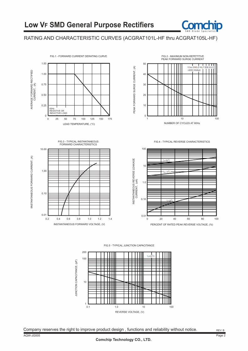
RATING AND CHARACTERISTIC CURVES (ACGRAT101L-HF thru ACGRAT105L-HF)
Comchip Technology CO., LTD.Page 2
Company reserves the right to improve product design , functions and reliability without notice.
FIG.1 - FORWARD CURRENT DERATING CURVE
FIG.3 - TYPICAL INSTANTANEOUSFORWARD CHARACTERISTICS
AV
ER
AG
E F
OR
WA
RD
RE
CT
IFIE
DC
UR
RE
NT
, (
A)
1.00
1.50
0.75
0.50
0.25
IIN
STA
NTA
NE
OU
S F
OR
WA
RD
CU
RR
EN
T, (A
)
0.10
1.00
10.00
0.01
0.2 0.4 0.6 0.8 1.0 1.2 1.4
0
0 25 50 75 100 125 150 175
LEAD TEMPERATURE, (°C)
INSTANTANEOUS FORWARD VOLTAGE, (V)
RESISTIVE OR INDUCTIVE LOAD
60Hz
Low VF SMD General Purpose Rectifiers
AQW-JG005
REV: B
FIG.2 - MAXIMUM NON-REPETITIVEPEAK FORWARD SURGE CURRENT
PE
AK
FO
RW
AR
D S
UR
GE
CU
RR
EN
T, (A
)
NUMBER OF CYCLES AT 60Hz
0
10
50
40
20
1 10 100
PERCENT OF RATED PEAK REVERSE VOLTAGE, (%)
FIG.4 - TYPICAL REVERSE CHARACTERISTICS
INS
TA
NTA
NE
OU
S R
EV
ER
SE
LE
AK
AG
EC
UR
RE
NT
, (uA
)
0.010
0.10
1.0
10
100
40 60 80 100
30
20
FIG.5 - TYPICAL JUNCTION CAPACITANCE
REVERSE VOLTAGE, (V)
0.1
JUN
CT
ION
CA
PA
CIT
AN
CE
, (p
F)
200
1.0 10 100
10
100
1
Comchip Technology CO., LTD.Page 3
Company reserves the right to improve product design , functions and reliability without notice.
Low VF SMD General Purpose Rectifiers
AQW-JG005
REV: B
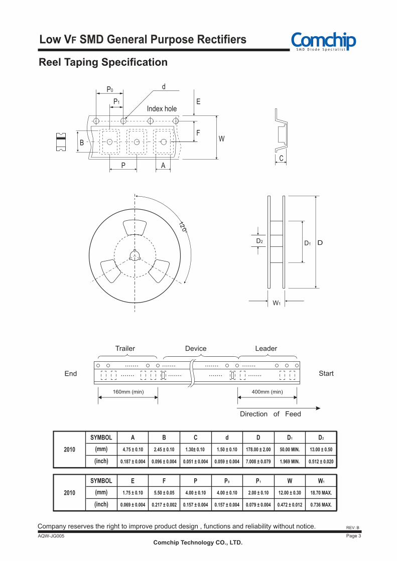
Reel Taping Specification
C
Index hole
d
E
F
B W
P
P0
P1
A
o
12
0
Trailer Device Leader
400mm (min)160mm (min)
.......
.......
....... ..............
....... ..............End Start
Direction of Feed
D1 D
W1
D2
B C d D D2D1
E F P P0 P1
SYMBOL
W W1
(mm)
(inch) 0.187 ± 0.004 0.096 ± 0.004 0.051 ± 0.004 0.059 ± 0.004 7.008 ± 0.079 1.969 MIN. 0.512 ± 0.020
SYMBOL
(mm)
(inch) 0.069 ± 0.004 0.217 ± 0.002 0.157 ± 0.004 0.157 ± 0.004 0.079 ± 0.004 0.472 ± 0.012 0.736 MAX.
4.75 ± 0.10 2.45 ± 0.10
4.00 ± 0.10
1.50 ± 0.10
5.50 ± 0.051.75 ± 0.10
50.00 MIN. 13.00 ± 0.501.30± 0.10
4.00 ± 0.10 2.00 ± 0.10 12.00 ± 0.30 18.70 MAX.
178.00 ± 2.00
A
2010
2010
Comchip Technology CO., LTD.Page 4
Company reserves the right to improve product design , functions and reliability without notice.
Low VF SMD General Purpose Rectifiers
AQW-JG005
REV: B
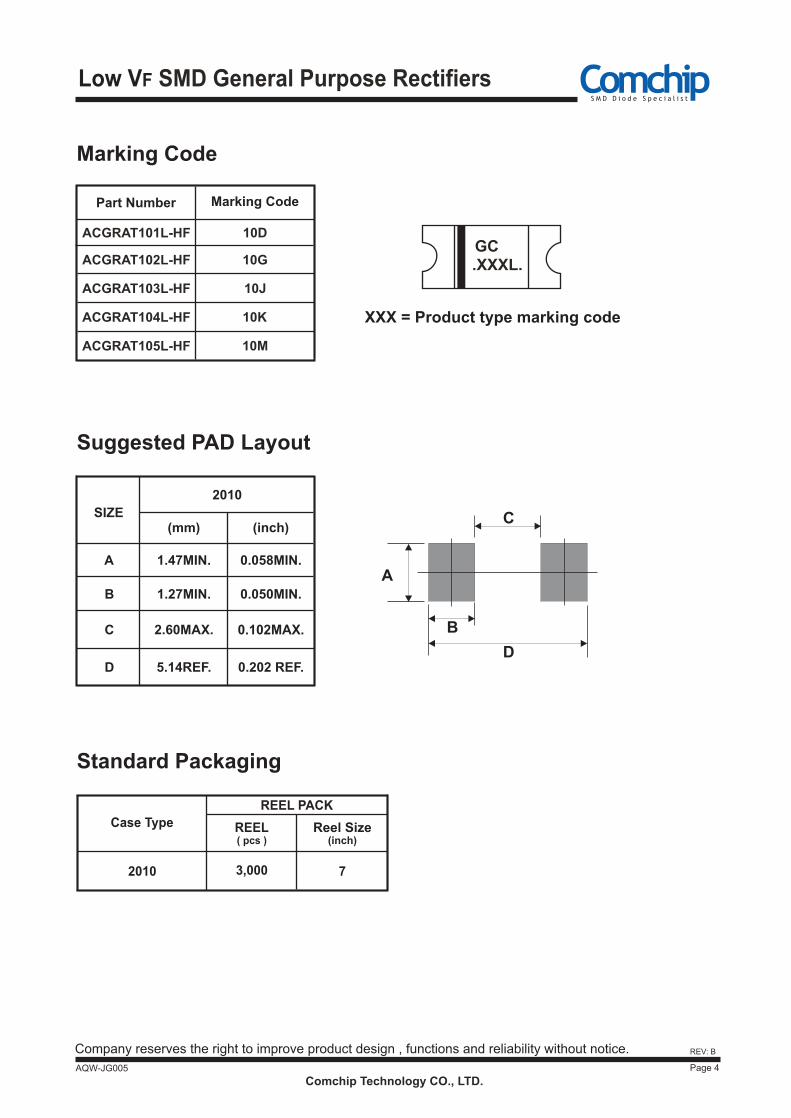
Marking Code
10D
Part Number Marking Code
ACGRAT101L-HF
ACGRAT102L-HF
ACGRAT103L-HF
10G
10J
ACGRAT104L-HF 10K
ACGRAT105L-HF 10M
XXX = Product type marking code
GC.XXXL.
Standard Packaging
Case Type
3,000
REEL( pcs )
Reel Size(inch)
7
REEL PACK
2010
Suggested PAD Layout
A
B
CSIZE(inch)
0.058MIN.
(mm)
1.47MIN.
1.27MIN.
2.60MAX.
0.050MIN.
0.102MAX.
2010
5.14REF. 0.202 REF.
A
B
C
DD