hard glass x-ray tubes in oil - meet philips research bound... · hard glass x-ray tubes in oil by...
TRANSCRIPT

OCTOBER 1941 . 309
HARD GLASS X-RAY TUBES IN OIL
by J. H. van der TUUK.
The use of hard glass has made it possible considerably to decrease the dimensions of all-glass X-ray tubes. When the tube is placed in an earthed metal jacket in order to protecttbe user against·high voltage, the space between tube and jacket may be filled with oilwhich promotes the voltage security and the heat dissipation. By a suitable constructionof the anode it is possible to adapt the tube to very high continuous loads. Various X-raytubes developed on these principles for medical diagnosis, therapy and the testing ofmaterials are described in this article.
The X-ray tubes in general use ten or twentyyears ago were actually not "tubes" but rather"bulbs", considering the form of the glass containerIn which the electrodes were placed (fig· 1). This
Fig. 1. An X-ray tube such as was used around 1920. Becauseof the bulbous shape the glass container suffers less from thebombardment by secondary electrons.
bulb form sprang from the desire to keep the glasswall at some distance from the electrode on whichthe X-radiation was excited by electron bombard-ment. If the distance was too small the glass wallexhibited very intense fluorescence which wasfound to be unfavourable for the life of the instru-ment: the bombardment of the wall by secondaryelectrons, which was the cause of the fluorescencecaused at the same time a gradual destruction ofthe glass by heating and electrolytic attack, andfreed gases from the glass which gradually spoiledthe vacuum in the tube and finally usually causedbreakdown through the glass.
Increasing the distance between electrode an:dwall in an attempt to decrease this danger, was ofitself not a very fortunate solution. The disadvan-tages became particularly evident when it wasunderstood that it was necessary in practice toprotect the user absolutely from the X-radiationoutside the effective beam and from the highvoltage. The bulbous form of the X-ray tubes madeit difficult to introduce the necessary lead jacketsand earthed metal coverings since the resultingconstructions were much too large and expensive.
A fundamental improvement in the situation wasfirst presented by the construction of the so-calledmetal tubes 1). In such tubes the discharge spacefrom which the secondary electrons originate is
621.386.1
surrounded by a chrome-iron cylinder to whichglass sleeves are welded to serve as insulation forthe electrodes. Since the metal cylinder is extremelyinsensitive to the electron bombardment, thediameter of the cylinder could be small.Later it was also found possible to decrease the
dimensions of the all-glass tubes considerably, bythe use of har dgl ass. Hard glass is in generalmuch more resistant to electron bombardment sinceit is not so strongly electrolysed as soft glass, andit has a much greater electrical resistance andresistance to breakdown. Due to the high resistancethe glass, which is negatively charged by an electronbombardment, retains the charge and therebyrepels further electrons. Moreover, hard glass hasa much smaller linear coefficient of thermal ex-pansion than ordinary soft glass, namely about45 X 10-7 jOe Instead of about 90 X 10-7 ;oe, so thatit has less tendency to break upon local heating.
Just as in the construction of the tubes with ametal intermediate section it was a necessary con-dition that the chromeiron should have about thesame coefficient of expansion as the ordinary kindsof glass used with it. in the construction of thehard-glass tubes it was also of great importancefor making the relatively large anode leads to haveat one's disposal alloys whose thermal expansionis as well adapted to that of the hard glass. An alloyof iron, nickel and cobalt satisfies this requirementover the whole temperature region from about 0 oeto beyond the softening interval of the glass.When it is taken into account that the fundamen-
tal idea, with the "metal" as well as with the hard-glass tubes, is to make the tube wall which is struckby secondary electrons of a material which is moreresistant to this bombardment, and that in bothcases devices are also employed to limit the numberof secondary electrons which can reach the tubewall, there no longer seems to be very much dif-ference between the two types of tube. Neverthe-less in the further development of the tubes, when
1) A. Bouwers, Fortschr. Röntgenstr. 32,41,1924; Radio-logy 13, 191, 1929;
310 PHILlPS TECHNICAL REVIEW Vol. 6, No. 10
it is a question of making a unit which is secureagainst high voltage and radiation, there are dif-ferent constructive possibilities in the two cases ..In the case of the former (metal) tubes the earthedjacket, usually filled with a gaseous or liquid in-sulation material, can be fastened to the chrome-iron intermediate section which is likewise earthed.
suitable for the highest D.e. and A.C. voltages usedin diagnosis, namely up to 100 kVmax, thanks inpart to the high resistance to breakdown of the oilin which the tube is immersed when in use. Thisresistance to breakdown, which amounts to 200kV/cm for good fresh transformer oil, can withproper use scarcely fall below 60 kVlcm even for
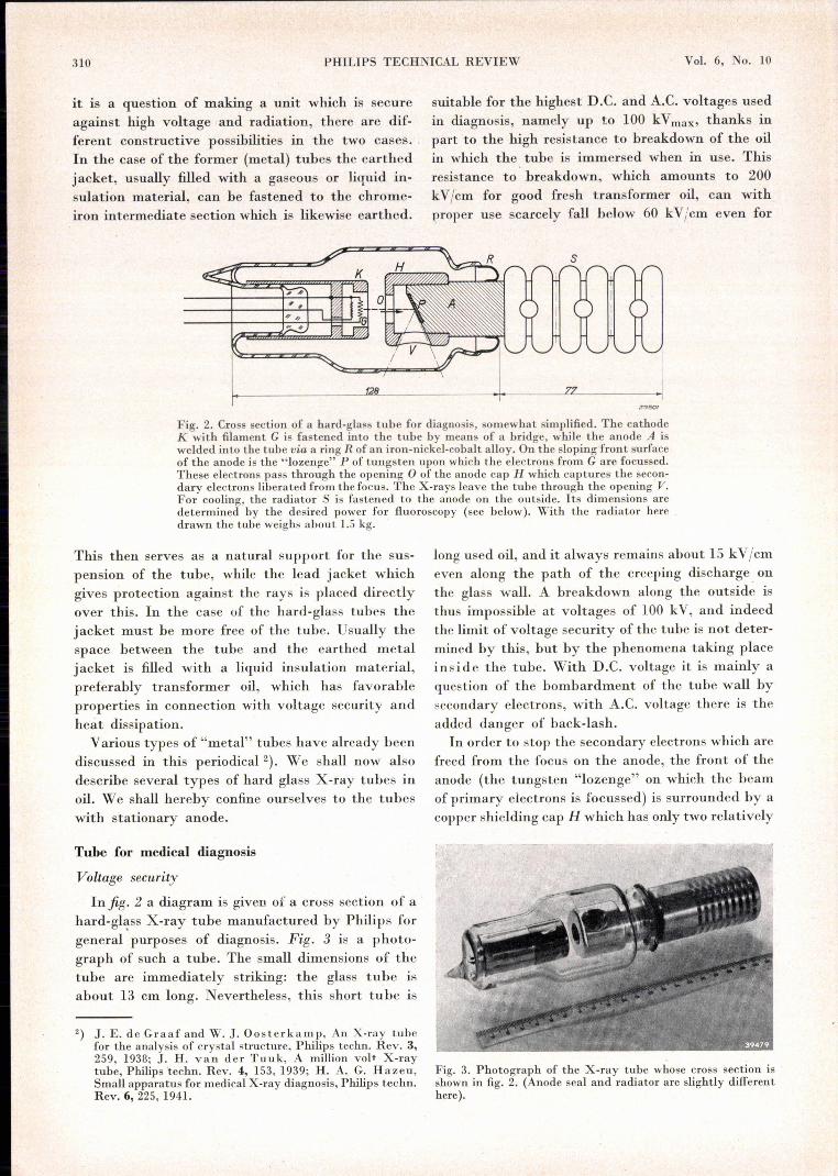
Fig. 2. Cross section of a hard-glass tube for diagnosis, somewhat simplified. The cathodeK with filament G is fastened into the tube by means of a bridge, while the anode A iswelded into the tube via a ring R of an iron-nickel-cobalt alloy. On the sloping front surfaceof the anode is the "lozen~e" P of tungsten upon which the electrons from Gare focussed.These electrons pass through the opening 0 of the anode cap II which captures the secon-dary electrons liberated from the focus. The X-rays leave the tube through the opening V.For cooling, the radiator S is fastened to the anode on the outside. lts dimensions aredetermined by the desired power for fluoroscopy (see below). 'With the radiator heredrawn the tube weighs about 1.5 kg.
This then serves as a natural support for the sus-pension of the tube, while the lead jacket whichgives protection against the rays is placed directlyover this. In the case of the hard-glass tubes thejacket must be more free of the tube. Usually thespace between the tube and the earthed metaljacket is filled with a liquid insulation material,preferably transformer oil, which has favorableproperties in connection with voltage security andheat dissipation.
Various types of "metal" tubes have already beendiscussed in this periodical ê]. We shall now alsodescribe several types of hard glass X-ray tubes inoil. We shall hereby confine ourselves to the tubeswith stationary anode.
Tube for medical diagnosis
Voltage security
Infig.2 a diagram is given of a cruss section of ahard-glass X-ray tube manufactured by Philips forgeneral purposes of diagnosis. Fig. 3 is a photo-graph of such a tube. The small dimensions of thetube are immediately striking: the glass tube isabout 13 cm long. Nevertheless, this short tube is
2) J. E. de Graaf and W. J. Oosterkamp, An Xvruy tubefor the analysis of crystal structure, Philips techno Rev. 3,259, 1938; J. H. van der Tuuk, A million vol+ X-raytube, Philips techno Rev. 4, 153,1939; H. A. G. Hazeu,Small apparatus for medical X-ray diagnosis, Philips technoRev. 6, 225, 1941.
long used oil, and it always remains about 15 kV/cmeven along the path of the creeping discharge. onthe glass wall. A breakdown along the outside isthus impossible at voltages of 100 kV, and indeedthe limit of voltage security of the tube is not deter-mined by this, but by the phenomena taking placeinside the tube. With D.e. voltage it is mainly aquestion of the bombardment of the tube wall bysecondary electrons, with A.C. voltage there is theadded danger of back-lash.In order to stop the secondary electrons which are
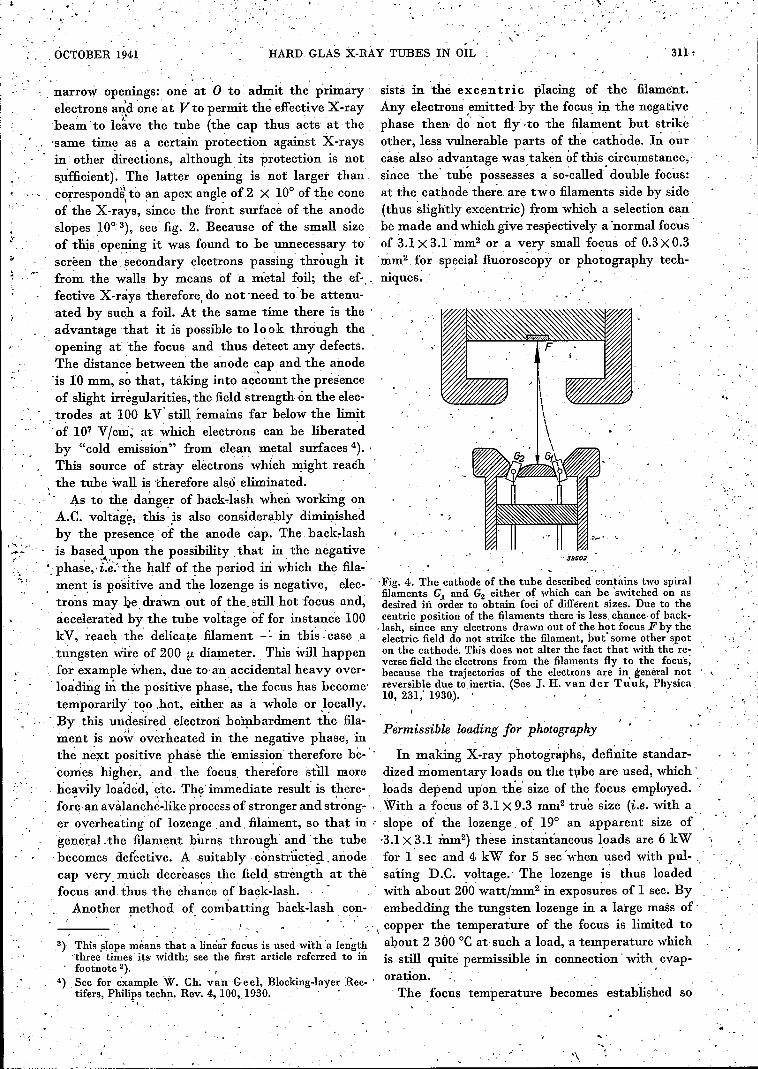
freed from the focus on the anode, the front of theanode (the tungsten "lozenge" on which the beamof primary electrons is focussed) is surrounded by acopper shielding cap H which has only two relatively
Fig. 3. Photograph of the X-ray tube whose cross section isshown in fig. 2. (Anode seal and radiator are slightly differenthere ).
.....
, '
'. ,OCTOBER 1941 '"HARD GLAS X-RAY TUBES IN OIL 311,
, narrow openings: one at 0 to' admit the primaryelectrons an'd one 'at V to permit th~ effective X-raybea~ to le~ve the tube (the cap thus acts at the-same time as a certain protection against X-raysin' other directions, although its protection is nots~fficient). The latter opening is not larger thancorrespondè to ~mapex angle of2 X 10° of the coneof the X-rays, since the frottt surface of the anodeslopes 10° 3), see fig. 2. Because of 'the small sizeof this ,opening it was found to be unnecessary toscreen the .secondary electrons passing through itfro~ the w~lls by means of a metal foil; the. ef-, 'feetive X-rays therefore, do not need to,'he attenu-ated by such a foil. At the same time there is theadvantage that it is possible to look through theopening at the focus and thus detect any defects.The distanc~ between the anode cap and the anode'is 10 mm, s~ that, taking into account the présenceof slight irregularities, the field strength on the elec-
, ,trodes at 100 kV' still remains far below the limitof 107 V/cm, at which electrons can be liberatedby "cold emission" from clean metal surfaces 4). 'This source of' stray electrons which might reachthe tube wall is therefore also eliminated. ', .. , - .
, .- As to the danger of hack-lash when working onA.C. voltage, this' ,is al~o considerably diminishedby the presence of the anode cap. The back-lashis based upon the possibility that in the negative
, ,<I. , '
" phase" i:e~"t?e half of the period ill which the fila"ment is positive and the lozenge is negative, elec-'trons may ~e, drawn ,out of the. still hot focus and,accelerated by the tube voltage of for instance 100kV, ~each the' delicate filament _: in thi~, case a.fungsten wire of 200 !.I. diameter. This will happenfor example when, due to an accidental heavy over-Ioading ill the positive phase, the focus has become'temporarilytoo .hot, either as à. whole or ,l?cally.
, By this undesired, electron bombardment the fila- 'Permissible loading' [or photography'ment is now overheated ID the negative phase, in 0 :r
thé next positive phase the emission therefore be-" In making X-ray photographs, defici.te standar-'conies higher, and the focus, theréfore still more dized momentary loads on the tube are used, which', heavily loaded, etc. The immediate result' is there-, loads depend upon the size of the focus employed. "fore, an avalanche-like process of strongerand strong- . With a focus of 3.1 X 9.3 rn~2 true size (i.e. with aer overheating of lozenge, and, filament, so that in : slope of the lozenge, of 19° an apparent size of ,gene:r:aLthe filament burns through and 'the tube '3.1 X 3.1 inm2) these instantaneous loads are 6 kWbecomes defective. A suitably. constructed .anode for i sec and 4 kW for 5 sec 'when used with pul- "cap very, much decreases the field, strength at the' sating D.C. voltage.' The lozenge is thus loadedfocus and thus the chance of back-lash. ' " with about 200 watt/mm'' in exposures of I sec. By
Ano~her method of. oombatting back-lash con- embedding the tungsten lozenge in a large mass of," . " " ';", copper the température of the focus is limited to
3) Thls ,slopemeans that a linéa~focus is used 'with a length about 2 300 oe at such a load, a temperature which'three times its width; see the first article referred to in is still, quite permissible in connection' with, evap-footnote 2). ,
oration.4) ,See for example W. Ch, van Geel, Blocking-layer Ree- 'tifers, Phili:ps techno Rev. 4, 100,,1930. The focus temperafure becomes established so
.~.........~
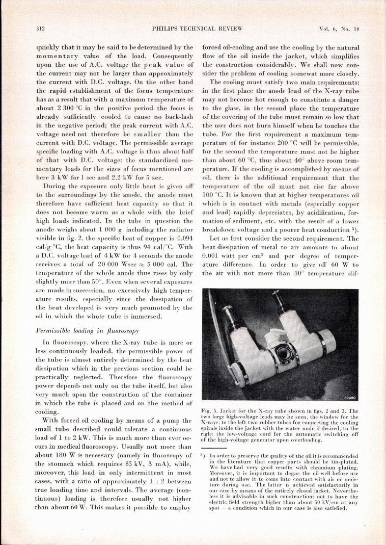
sists in thé excen t r ic placing of the filament.Any electrons ,emitted by the focus. ÏI;l the negativephase then do' not fly -to the filament but strikeother, less vulnerable parts of the cathode. Iri. ourcase also advantage was. taken of this circu.mstance,·'si~ce the' tub~ possesses a 'so:callea" double focus:at the cathode there are two filaments side by side(thus ~lightly excentric) from which a selection canbe rnade and which give respectively a 'normal focusof 3.1 X 3.1 mm'' or a very small focus of 0.3 X 0.3mm2 for special fluoroscopy or photography tech-niques.
'"
,','Fig. 4. The cathode of the tube described contains two spiralfilaments G~ and G2 either of which can be 'switched, on asdesired In order to obtain foci of different sizes. Due to thecentric position of the filaments there is less."chance of back-. lash, since any electrons drawn out of the hot focus F by theelectric field do not strike the filament, but' some other spoton the cathode. This does not alter the fact that with the .re-verse field the electrons from the filaments fly to the focus,because the trajectories of the electrons are in general notreversihle due to inertia. (Sce J. H. van der T'u uk, Physica10, 231; 1930). '
, ,'\<,. '
312 PHILlPS TECHNICAL REVIEW Vol. 6, No. 10
quickly that it may be said to be determined by themomentary value of the load. Consequentlyupon the use of A.C. voltage the peak value ofthe current may not be Iarger than approximatelythe current with D.C: voltage. On the other handtbe rapid establishment of the focus temperaturehas as a result that with a maximum temperature ofabout 2 300 oe in the positive period the focus isalready sufficiently cooled to cause no back-lashin the negative period; the peak current with A.C.voltage need not therefore be sm a11e l' than thecurrent with D.e. voltage. The permissible averagespecific loading with A.C. voltage is thus about halfof that with D.e. voltage: the standardized mo-mentary loads for the sizes of focus mentioned arehere 3 kW for 1 sec and 2.2 kW for 5 sec.
During the exposure only little heat is given offto the surroundings by the anode, the anode m~sttherefore have sufficient heat capacity so that itdoes not become warm as a whole with the briefhigh loads indicated. In the tube in question theanode weighs about 1 000 g including the radiatorvisible in fig. 2, the specific heat of copper is 0.094caljg °C, the heat capacity is thus 94 caI;oC. Witha D.C. voltage load of 4 kW for 4 seconds the anodereceives a total of 20 000 Wsec R::; 5 000 cal. Thetemperature of the whole anode thus rises by onlyslightly more than 50°. Even when several exposuresare made in succession, no excessively high temper-ature res ults, especially since the dissipation ofthe heat developed is very much promoted by theoil in which thc whole tube is immersed.
Permissible loading in fluoroscopy
In fluoroscopy, where the X-ray tube is more orless continuously loaded, the permissible power ofthe tube is almost entirely determined by the heatdissipation which in the previous section could hepractically neglected. Therefore the fluoroscopypower depends not only on the tube itself, but alsovery much upon the construction of the containerin which the tube is placed and on the method ofcooling.With forced oil cooling by means of a pump the
small tube described could tolerate a continuousload of 1 to 2 kW. This is much more than ever oc-curs in medical fluoroscopy. Usually not more thanabout 180 W is necessary (namely in fluorscopy ofthe 'stomach which requires 85 kV, 3 mA), while,moreover, this load in only intermittent in mostcases, with a ratio of approximately 1 : 2 betweentrue loading time and intervals. The average (con-tinuous) loading is therefore usually not higherthan about 60W. This makes it possible to employ
forced oil-cooling and use the cooling by the naturalflow of the oil inside the jacket, which simplifiesthe construction considerably. We shall now con-sider the problem of cooling somewat more closely.
The cooling must satisfy two main requirements:in the first place the anode lead of the X-ray tubemay not become hot enough to constitute a dangerto the glass, in the second place the temperatureof the covering of the tube must remain so low thatthe user does not burn himself when he touches thetube. For the first requirement a maximum tem-perature of for instance 200°C will be permissible,for the second the temperature must not be higherthan about 60°C, thus about 40° above room tem-perature. If the cooling is accomplished by means ofoil, there is the additional requirement that thetemperature of the oil must not rise far above100 oe. It is known that at higher temperatures oilwhich is in contact with metals (especially copperand lead) rapidly depreciates, by acidification, for-mation of sediment, etc. with the result of a lowerbreakdown voltage and a poorer heat conduction 5).
Let us first consider the second requirement. Theheat dissipation of metal to air amounts to about0.001 watt per cm2 and per degree of temper-ature difference. In order to, give off 60 W tothe air with not more than 40° temperature dif-
Fig. 5. .Tacket for the X-ray tube shown in figs. 2 and 3. Thetwo large high-voltage leads may be seen, the window for the
, X-rays, to the left two rubber tubes for connecting the coolingspirals inside the jacket with the water main if desired, to theright the low-voltage cord for the automatic switching offof the high-voltage generator upon overloading.
5) In order to preserve the quality of the oil it is recommendedin the literature that copper parts should he tin-plated.We have had very good results with chromium plating.Moreover, it is important to degas the oil well before useand not to allow it to come into contact with air or mois-ture during use. The latter is achieved satisfactorily inour case by means of the entirely closed jacket. Neverthe-less it is advisable in such constructions not to have theelectric field strength higher than about 50 kV/cm at anyspot - a condition which in our case is also satisfied.

. i:
" "
'.-"'~~~'-~,-'~--"-" ~-,-,-~~--,-~-~~~.'"',,
.~.;""\ .. ,~ : c ' • \ , - . , "
HARD GLAS X-RAY TUBES IN OIL,','
OCTOBER 1941
ference, therefore, the earthed jacket of the tubemust have a surface of 1500 cm2• This can be achievedwith a relatively small' and therefore quite light
, 'jacket: the jacket shown in jig. 5 'made -of brasssheet; together with tube and oil. but; without thecable, weighs only slightly more than 7 kilograms ...When in this, way a temperature of not more
, thait 60 oe is 'gua~anteed -for the jacket, provision, may" be 'made by suitable construction that thetemperature of, the flowing oil will, never becomeappreciably higher, except in a th~ layer close tothe 'radiator. This radiator whose function is thetransfer' of- heat from the anode block to the oil
, .is in guod contact with the anode and has a surfaceof about' 200 cm 2• ,The heat' dissipátion of fuétalto oil for' cases 'of,natural flow ~ a relatively smallspace amounts to about 0.03 W per 'cm2 and "perdegree temperature difference, according to meas-'uréments ~carrie'd out in' this laboratory.' This valueis valid for an oil temperature of about 60°C; at
, , a higher temperature the heat dissipation increases'.', b'ecause of the fall in viscosity which' permits mote'
rapid flow. With this heat dissipation it may hecalculated that for the' dissipation of 60 W, 'the "radiator ni.ust be about, IOC?warmer .than the oil.
_., We must, hO'we~er; keep in mind tha,t'the power"~, óf. 60 W represents an average, load resulting, from':i~-'::.,~inter~ittent loading 1 : 2 with 180 W. We may, t . ~_~_-: --~ 'w i '_. . ......
·.....·here·assume of course that the temperature of the:.", :._';:~ <"iIJwing 'Oil~i1;h its great ~èat capacity is deterniine:d
only by .the average load, and' thus' amounts 'to60'oC;'in'and-clóse to theradiator, howevèr.twliere'the 'temper~ture equilibrium' is ,est~blished" muchmore, quickly, the temperature during the workingperiod must be calculated for alieat dissipa'tion180j6d' ',3 times ~s Iarge., In the working-period,th:e:éefo~e: ,thè, temperature difference .hetwéen ':ràäiator ~d óilis 300;so th~t we-find atémperatureof 60 +"30 -, 90'óC for the ràdiator, ". , 'This is'thé temperáture averaged-over the whole
surfaèe+of the radiator ...In this radiator "which l's7.5 cm long, there is also a tempera'ture drop. Inour case for a dissipation-of 180W (wor~g' period) ,this drop amounts to about 20° so that the end ofthe radiator will be about 10°'colder and the be- ,ginning about 10° warmer than the average. In,the neighbourhood of the scal,' therefore, a tem-
• perature of about 100 PC occurs which is indeed, allowable for long times. . " ,
For those caSes in which the dissipation of l8.0 Wintermittent 1': 2 is not sufficient, which maysometimes occur in. very busy clinics, the jacket'with the sn;face area of 1500 cm2 would not be able
. to dissipate the he~t -developed without exc~eding...' ;'". ' .
"
.'.•~
"
313
, "'the permissible temperature. In order to' adapt thetube for150 to 180 W con tÜi. u ou scharge, a jacketwith a surface area ó'fabout 4000 cm2 would have tobe constructed ..!t is, however, aÎso possible to conti-nue to work with the convenient small jacket offig. 5if the oil fu it is co'ol~d. .This can be d~ne in the .familiar way, he introducing a 'fixed 'cooling spiralinto' the 'jacket, through which water ;'from the !
mains is 'allówed to circul~te when the higher loadon the tube is employed.' This, is the solution wehave chosen. The' connection to the water main'. ,
is by means of two thin rubber tubes along, one .ofthe high-voltage cables already present. For. therest the heat capacity of the whole is such that the
" tube can be used for about '15 minutes with 180 W . ." 'Withont water' eooling, heginning ~ith the, coldstate. Only after ,the' 15 minutes mentioned -is the ,permissible liI~lÏt of thè' temperature ):eached, and .:this may be seen on an indjcato~ connected with an 'expansion box fastened to the' jacket· (the oil ex-.'p~nds' 0.07 percent per" degree; see 'also the Lastarticle referred to in footnote 2)). If the load. istoo heavy, i.e, if the expansion box expands still .farther, it automatically- switches off the primaryvoltage of the high-voltage 'transformer. ': ., Upon the use of water cooling, the 'permissible
continuous load is eveneconsiderably higher than'180 'watts, By using a sufficiently. high speed of flowof the' cooling water thetoil can be kept practically "at 'room temperature ,'fiibout ' 30°C) even Withpowe~s :of 300 W. For-the t.emperature differe'ucebetween radiato~ (middle). and' oil we find .a~,out50° for 300 W, for the' temperature drop in theradiator about 34°, so thát the anode seal neèd notbecome warmer than' 30 + 50 + 17 " 97 oe. 'Thetemperature drop' in the an'o d e from the focus-tothe beginning of the r'adiator amounts to about 55°,'the focus thu~· :has it temperature of' only 'about150°C, while temperatllr~s up to' 400 oe in 'contm-
- uous usage may· be considered'. quit~' perniissible.'We may' thérefore 'd~vdop.a powerofMO w.ormore continuously in the tube ';Vith no disa!lv~Î1.~
J - " . .• . _. ._' ,' ... ~ .......
"tage, and this is often desirable in the macro~C;9:p;i~ ,'e xa mina tion of-ma t er ia l s fo~ .which ~thisr~tiilie ..~.•may also he used." ~.' . ,.~.,~.~" ...', ~ .'.~\.,.~
",-~
" ~
'f. -.
r;
Fig. 6. Hard-glass tube for diagnosis of the type customary. untillately, in 'which the anode seal R is welded into a depres-sion jn the tube. " . ' •
,. ".~
314 PHILIPS TECHNICAL REVIEW Vol. 6, No. 10
These heavy continuous loads have been made possible hereby the way in which the anode lead is fused into the tube.In the tube constructions common until now this weld wasmade in a concavity of the tube according to the sketchbelow (fig. 6), which is the simplest method for manufacture.Due, however, to the fact that the cooling body can only berelatively thin here and the flow of oil inside the depression Iis very much hindered, a larger temperature difference be-tween cooling body and oil and a greater temperature drop inthe cooling body S occurs for a given heat dissipation, FO thatthe seal and the oil become much warmer at that spot thanis the case with the tube according to fig. 2 with the flat anodeseal. In the case of such small tubes with this type of seal in adepression it is impossible to go higher than 150 watts contin-uous even with strong water cooling of the jacket.
diagnosis fig. 2, but larger in size. BecaU:se of thegreater danger from secondary electrons at thesevoltages the anode cap H is made so deep that onlyabout one per cent of the secondary electrons areable to fly back through the opening O. Further-more, the opening V is closed to secondary electronsby a beryllium window 1 mm thick. The largerdiameter of the tube (and thus also of the jacket)makes it desirable to have the undesired X-raysabsorbed as far as possible by the anode cap in thiscase. The latter is therefore made of fairly thicktungsten copper so that the absorption in all di-rections corresponds at least to about 5 mm of lead
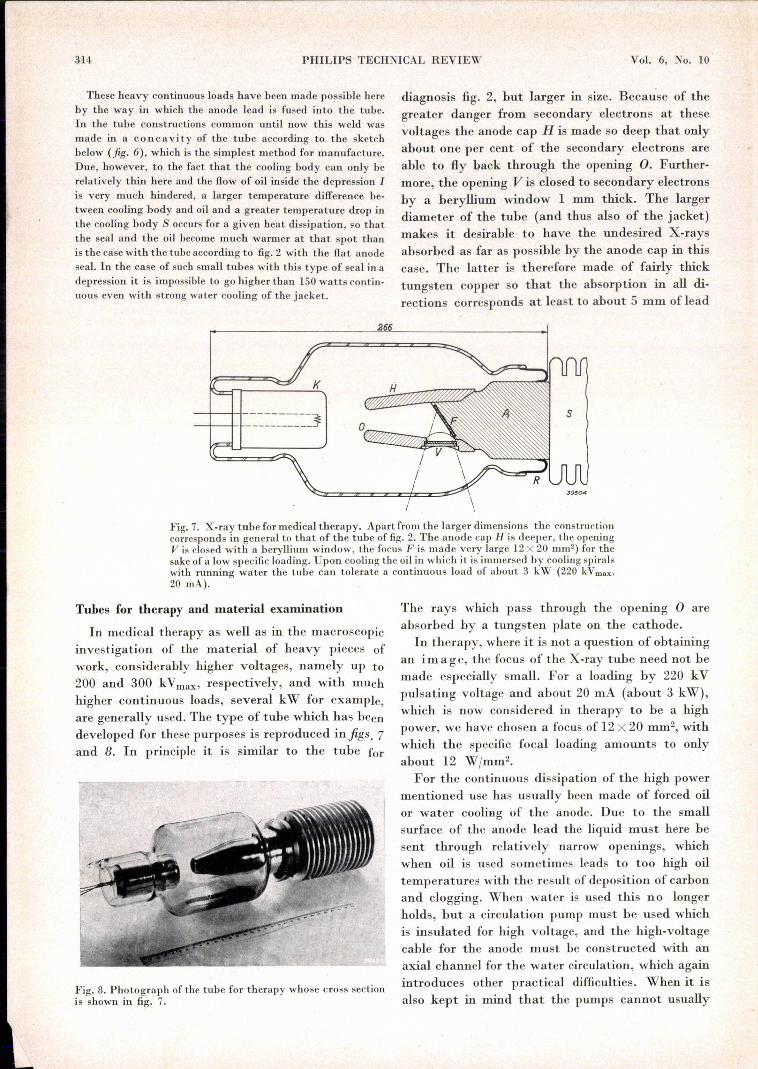
Fig. 7. X-ray tube for medical therapy. Apart from the larger dimensions the constructioncorresponds in general to that of the tube of fig. 2. The anode cap H is deeper, the openingV is closed with a beryllium window, the focus F is made very large 12 X 20 mm2) for thesake of a low specific loading. Upon cooling the oil in which it is immersed by cooling spiralswith running water the tube can tolerate a continuous load of about 3 kW (220 kVmax,
20 mA).
Tubes for therapy and material examination
In medical therapy as well as in the macroscopicinvestigation of the materialof heavy pieces ofwork, considerably higher voltages, namely up to200 and 300 kVmax, respectively, and with muchhigher continuous loads, several kW for example,are generally used. The type of tube which has beendeveloped for these purposes is reproduced infigs. 7and 8. In principle it is similar to the tube for
Fig. 8. Photograph of the tube for therapy whose cross sectionis shown in fig. 7.
The rays which pass through the opening 0 areabsorbed by a tungsten plate on the cathode.In therapy, where it is not a question of obtaining
an image, the focus of the X-ray tube need not bemade especially small. For a loading by 220 kVpulsating voltage and about 20 mA (about 3 kW),which is now considered in therapy to be a highpower, we have chosen a focus of 12 X 20 mm", withwhich the specific focal loading amounts to onlyabout 12 W/mm2.For the continuous dissipation of the high power
mentioned use has usually been made of forced oilor water cooling of the anode. Due to the smallsurface of the anode lead the liquid must here besent through relatively narrow openings, whichwhen oil is used sometimes leads to too high oiltemperatures with the result of deposition of carbonand clogging. When water is used this no longerholds, but a circulation pump must be used whichis insulated for high voltage, and the high-voltagecable for the anode must be constructed with anaxial channel for the water circulation, which againintroduces other practical difficulties. When it isalso kept in mind that the pumps cannot usually
. ' ,~. ;.... ":.,. ..... ;,i". ~
.~";" -- :'
OCTOBER ,1941 HARD GLAS X-RA;Y TUBES IN OIL ' ,315
he niad~ noiseless, it is' cl~ar that it is a great ad-.vantage to be able to do without forced cooling.
< We .have indeed succeeded in this aim" by theapplication of the principles already described in'connection with the tube for diagnosis, but with
, larger dimensions than there used. A radiator with',1:-
:'t
' ... '
.>,
_ •. J950S
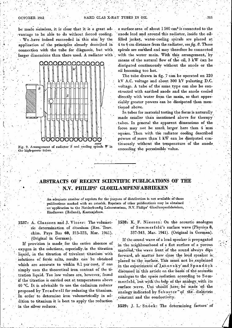
Fig. 9. Arrangement of radiator' Sand cooling spirals W inthe' high-power tubes. , ' . .,' , '
a surface area of .about 1500 cmê isconnected tothe;anode lead abd aro~nd this radiator, inside the oil-filled jacke~,' water-cooling, spirals are placed at''4' to 6 cm distance from the radiator, seefig. 8. Thesespirals. are earthed and may therefore be connectedwith the, water main. With' this arrangement,' bymeans of the natural How of th~ oil, 3 kW ëan bedissipated continuously without the anode or theoil becoming too hot.
The tube drawn in fig. ,7 can be operated on 220kV A.C. voltage 'and about 300 kV pulsating D.C.voltage. A tube of the sametype can also be con-structed with earthed anode and the anode cooleddirectly with water, from the, main, so that appre-ciably greater powers 'can be dissipated than men-tioned above., .
In tubes for material testing 'the focus is naturallymade smaller than ~entioned "above for therapy'"tubes. In general the apparent dimensions of thefocus may not he much, larger, here than 4 mmsquare. Then with the radiator cooling describedpowers of .more thauL kW can be dissipated con-t.inuously without' the temperature 'of the anodeexceeding the permissible value.
'. , ABSTRACTS OF' RECENT SCIENTIFIC PUBLICATIONS OF THE, '
, , " N.V. PHIL1PS' GLOEILAMPENFABRIEKEN ",
An adequate llll~ber of reprints for the purpose of distribution is not available óf thosepublications marked with an asterisk. Reprints of other publications may be obtained.'on' application 'to the Natuurkundig Laboratorium, N.V. Philips' 'Gloeilampenfabrieken,Eindhoven (Holland), Kastanjelaan. , '
1537: A. Claassen a:n:dJ. Visser: The volumet-ric determination of titanium (Rec.' Trav.chim. Pays Bas' 60, 213-223, Mar. 1941).(Original in German).
If provision !s made, for the entire absence of, " . oxygen in the solutions, especially. in the titration" liquid, in the titration of trivalent titanium' with, solutions of ferric salts, results .can be obtainedwhich are accurate to Within 0;1 per cent, if onesimply uses the theoretical iron content of the ti-tration liquid. Too low values ate, however, foundif the' titration is carried out at temperatures above40°C. It is advisable fo use the cadmium reducerproposed by Treadwell for reducing the titanium., In .order' to determine iron' volumetrically in ad-dition to titanium it is best to apply the redüctionin the silver reducer. " . ,
. ,
1538: .K. F. Niessen': On t~e acoustic analogueof Sommerfeld's surface wave (Physica 8,337-343, Mar. 1941). (Original in Ger~~n).
If the .sound wave of a loud speaker is propagatedin the neighbourhood of a Hat s~l.rface of a porOusmaterial, 'the "wave front ~f the sound 'always dipsfo~w:ard, ni> matter how' close the loud speaker is, '
, placed tothe surface. This ~us't' not 'be .explained 'in the ex$eriin,ellti ol.t~;iîo;vsky- and:Sp àniö ç k -discussed i~' this article on·,the' ba~is of thé' acou~iicanaloguetó the space radiation according-to Som- 'merfeld, 'but with' the help of tb,~ ~~klogy:with 'its.s:u:rface :wav~. :Us~ 'sh?ûId'~hère~'bi ~,~,d~ '~~. theanalogy indicated by Schu~.ter'·"~f. tlie ,diel~ctric
,,constant' mid the cond_ucti'0-ty: . ' , ~"
1539: J. L.- Sn ó ek: The determining f~ctors' of
"'- '
." ,.
;.
;,
~ >-. , ... ,
,'
, ...", '., , :',~.
...... ,
316"
PHILIPS TECHNICAL REVIEW Vol. 6, No. 10
. ";
tempt is unsuccessful n~ matter how the nU:mbèrof,3d electrons prescrihed byPauling are distrib-'uted among the levels of the ferromagnetic elec-tron hand, .
, '
1542: ',P. J., B.ouma: 'Physiological optical foun-o dations of the problenis of air-raid proteetion
blackout (Physica 8, 398-412, :Apr. 1941).(Original in Ge!man)..' "
1544:, M. J. O. St r u t t and A: van der Zièl:'what '
_t·"
quantities characterize the suitability of an'. electronic tube for 'the' amplification of theweakest signals?' [Physica: 8,' 424-425, Apr:
, .: 194,1)., (Original '_in Ge~man). , ' "
permeability (Physica 8, 344-346, Mar." 1941).
00 • The concept -defended in 1936 by, the authoro (cf 1078), that for homogeneous annealed alloys
, 'the permeability 'depends only upon the internalstresses and the crystal anisotropy, has- since been,confirmed by investigations of Grabbe on slowlyc~oled nickel-iron' alloys, and of W illi a ms' andBozorth on single crystals of iron and silicon-iron. -In contrast to this, however, the experiments which For the main points in the contentsof this article
. Snoek and Ra then a u recently carried out on ,the reader is referred to Plïilipstechn. Rev. 6, 161,cold worked nickel-iron alloys do .not show the least June 1941. Furthermore on the basis of 'new ex-:, agreement with this concept. ,It is highly probable perimental 'data nomograms have been constructedthat some unknown factor is here involved. from which the relation can be read off bet~een
, , , .the brightness at which a light spot can just be ,1540: J. F. Schouten: .De experimenten van observed and the angle-of vision at which it is seen. '
Se eb e ck met de sirene en de acoustische wet "van Ohm (Ned.T. Natuurk.8, 154-165,Apr. 1543: P. 'J. Bouma: The relation ,between the1941) (Seebeck's experiments with.' the "concepts Brightness and "Dunkellcucht-siren and Ohm'sacoustic law).. , dichte", etc. (Physica 8, 413-423, Apr. 1941)'.'
, " " '. -(Orimna,l'in German). ' , 'Various investigations on the' perception of, . 0- , ,', • " ,
sounds which-were carried out, by Seebeck: with: , " For the, contents of this; article' the reader is '",,': ',his siren in 1841 and which at th~t 'time led to a referred to Philips techn, Re~. 6;161, 1941.
,', lively discussion, since according to him they could" not be explained by the, acoustic law then proposed
by, 04m, were repeated by the' writer and ~onfirmed.It is found that on the basis of modern insight into
, ,subje~tive sound analysis (cf. Philips techn, Rev. 5,',' 286,1940) these phenomena can easily be explained, "andt~at. the -explanation lies ,in the, direction in
:: .. which, Se eb e ck sought: ~t 100 years ago. "In this article, emphasis is laid on the fact that
the ratio of the input noise .resistance to the Î1!put .resistance between control grid' and cathode is net
1541; .K. F. Niessen: On the testing of Pauting's a suitable quantity for the.characterization of the, 'hypothesis ~bout' the binding of th~ "atonis usefuhiess of an amplifier valve .for the -amplification
in metals,' (Physîca 8, 377-386, 'Apr. 1941). of jsmàll signals, More ,suitable for, this purpose is" " (O~iginal in, German.).' ",i' , ," , the ratio between.rhat part of the noise resistance
~All attempt, is made to' find a 'confirmation of ','which is' a result 'of fhictuations in the cathode cur-Paulihg'~~hypoth~sis about the binding ~f, the -rent and that part of.the inputlresistance which;atoms ill the metals scandium to copper from the .is a result of the transit times of the electrons in.. -..measured Curie temperature of nickel. This at-, the valve (cf. Philips techn.. Rev. 6,178, June 1941).
( .' , . .. . ~, '"
,...... '."
"
. ..:, , .
,I
.. ,',
, "
)01'."
.'
, . ~.._".:' ~ s, , ff
"
"
',
\ :.
"
. '•• ~~. . r
" ........ ,"
; ..-:t, JO'
r.
~; .'fJ .I .'.
.J.,