behavior of circular glass fiber reinforced polymer tubes under axial compression
DESCRIPTION
This project involves an evaluation of behaviour of circular GFRP tubes under axial compression. Circular tube columns having different length and cross sections resulting in the range of combinations of global and sectional slenderness, were tested under axial load. From this study, the compressive strength, ultimate load and failure modes were determined. After experimental investigation on evaluation of behavior of GFRP tubes, numerical investigation process is started, using ANSYS. Finite element models of the circular tubes will be generated and analyzed using SHELL elements. In this process orthotropic properties has been defined to align the material direction of the composite lay-up and stacking sequence. The experimental results were compared with the analytical results. It includes the parametric study of L/D and D/t ratio of various dimensions and orientation in finite element model. It gives the best orientation angle for the compressive behavior of GFRP tubesTRANSCRIPT
International Journal of Science and Engineering Applications
Volume 4 Issue 3, 2015, ISSN-2319-7560 (Online)
www.ijsea.com 110
Behavior of Circular Glass Fiber Reinforced Polymer Tubes Under Axial Compression
Yazhini A Ramesh Babu C
Mepco Schlenk Engineering College Mepco Schlenk Engineering College
Sivakasi – 626 005, Sivakasi – 626 005
Tamilnadu, India Tamilnadu, India
Abstract: This project involves an evaluation of behaviour of circular GFRP tubes under axial compression. Circular tube columns
having different length and cross sections resulting in the range of combinations of global and sectional slenderness, were tested under
axial load. From this study, the compressive strength, ultimate load and failure modes were determined. After experimental
investigation on evaluation of behavior of GFRP tubes, numerical investigation process is started, using ANSYS. Finite element
models of the circular tubes will be generated and analyzed using SHELL elements. In this process orthotropic properties has been
defined to align the material direction of the composite lay-up and stacking sequence. The experimental results were compared with
the analytical results. It includes the parametric study of L/D and D/t ratio of various dimensions and orientation in finite element
model. It gives the best orientation angle for the compressive behavior of GFRP tubes
Keywords: Circular Glass Fiber Reinforced Polymer (GFRP), Compressive, shell, Fiber orientation
1. INTRODUCTION
1.1 Fiber Reinforced Polymer
In recent years, fiber reinforced polymer (FRP) have been
used as an alternative for traditional materials. It have found
increasingly wide applications in civil engineering, both in the
new construction and in retro fit of existing structures. Fiber
Reinforced Polymer composites possess several advantages
over steel, due to high strength-to-weight ratio and good
corrosion resistance. For the retrofit of structures, Fiber
reinforced polymer has been used as an externally bonded
reinforcement has become very popular in recent years. [1] In
reinforced concrete column retrofit, FRP is primarily used as
an external jacket to provide confinement to the concrete core
. Confinement also enhances the compressive load capacity of
a concrete filled FRP tube column, and reduces the required
column cross-section compared to that of a conventional RC
column [3]. In the last 20 years, various authors have
addressed the performance and strength of pultruded GFRP
members subject to concentric compression. Daniel C.T.
Cardoso [5] derived the compressive strength equation for
square GFRP tubes. The buckling behavior and interaction
between crushing local and global buckling was observed.
Jeffrey Richard Mitchell [8] have studied optimal partial
concrete filling of frp and effect of d/t ratios for different
laminates.The relationship between optimal partial concrete
filling of frp and d/t ratio observed was linear.
1.2 Types of fibers The classification of FRP composites is based on the types of
fibers used as the reinforcement .There are three types of
fibers dominating civil engineering industry: Glass, carbon
and aramid fibers. Among these fibers Glass fibers plays a
predominant role.
1.3 Glass Fiber Reinforced polymer Glass fibers are a processed form of glass, which is
composed of a number of oxides (mostly silica oxide),
together with other raw materials (such as limestone,
fluorspar, boric acid, clay). They are manufactured by
drawing those melted oxides into filaments ranging from 3
mm to 24 mm. There are five forms of glass fibres used as the
reinforcement of the matrix material: chopped fibres, chopped
strands, chopped strandmats, woven fabrics, and surface
tissue.
Glass fiber reinforced polymer (GFRP) have gained
acceptance among civil engineers due to their advantages over
traditional construction materials: high strength to weight
ratio and superior corrosion resistance, for instance.
Additionally, large scale pultrusion of GFRP has contributed
to reducing manufacturing costs, making these products
competitive. Significant efforts are underway worldwide to
develop standard provisions for the design of GFRP structural
members. [2].
1.4 Member and section classification Columns are conventionally classified as being short,
intermediate or long based on their relative column
slenderness ratio. Depending upon slenderness ratio the
column generally fail by either local or global buckling.
2. EXPERIMENTAL PROGRAM GFRP hollow tubes of various cross sections having different
lengths and diameter were tested.12 specimens were taken
from 4 different batches of GFRP tubes. After arrangement
on compressive testing machine the GFRP tubes were applied
axial load. Axially compressive tests were processed to obtain
material properties and compressive strength.
Table1. Specimen Specification
Diameter
mm
No of
specimen
Length
mm
Thickness
mm
D/t
ratio
L/D
ratio
320
3
579
5
64
1.8
325
3
653
7.5
43.3
2
164
3
338
3
54.6
3
310
3
1200
5
62
3.8
International Journal of Science and Engineering Applications
Volume 4 Issue 3, 2015, ISSN-2319-7560 (Online)
www.ijsea.com 111
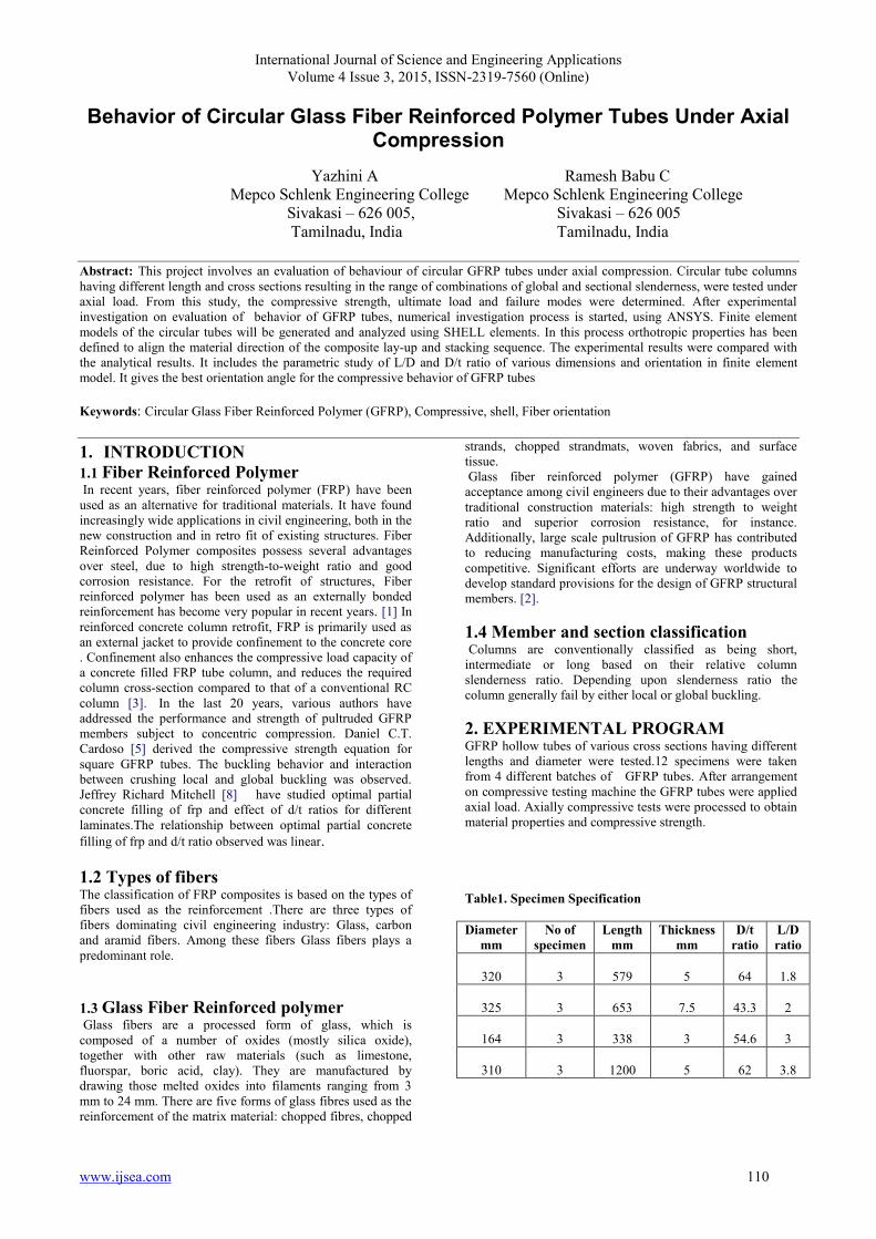
Figure 1Tubes of various cross Figure 2 Tubes Of Same Diameter Section 320 mm
2.1 Experimental Set-Up 2.1.2 Short GFRP tube In the compressive testing machine the hollow circular GFRP
tubes were fixed by using base plates. Axial load is applied at
the top of the plate and the load is transformed in the form of
udl to the tube. On reaching the particular load ,the tube
crushed at the bottom producing a longitudinal crack with a
large sound. The critical load at which the tube is crushed is
obtained and the tube with an increased thickness has
obtained more load value. The stress strain values are noted.
Figure 3. Experimental set-up for short tube
2.1.3 Long GFRP tube The tube with the increased length is tested in the column
testing frame. The bottom is fixed and at the top the axial load
is applied in the form of udl through the base plates. The load
is applied from the loading jack. The demec gauges are used
to obtain the strain values. The experimental set up is shown
in the figure 4.
Figure 4 . Experimental set-up for Long tube
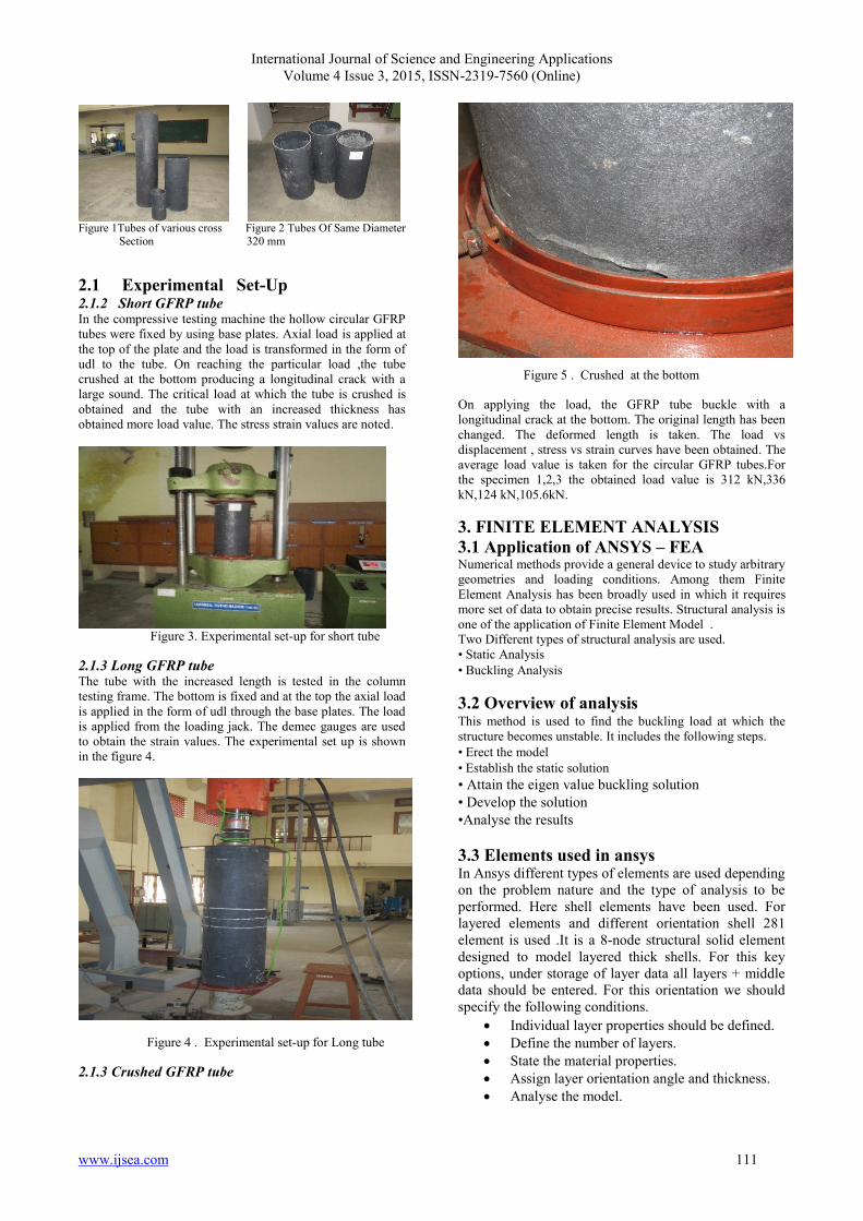
2.1.3 Crushed GFRP tube
Figure 5 . Crushed at the bottom
On applying the load, the GFRP tube buckle with a
longitudinal crack at the bottom. The original length has been
changed. The deformed length is taken. The load vs
displacement , stress vs strain curves have been obtained. The
average load value is taken for the circular GFRP tubes.For
the specimen 1,2,3 the obtained load value is 312 kN,336
kN,124 kN,105.6kN.
3. FINITE ELEMENT ANALYSIS
3.1 Application of ANSYS – FEA Numerical methods provide a general device to study arbitrary
geometries and loading conditions. Among them Finite
Element Analysis has been broadly used in which it requires
more set of data to obtain precise results. Structural analysis is
one of the application of Finite Element Model .
Two Different types of structural analysis are used.
• Static Analysis
• Buckling Analysis
3.2 Overview of analysis This method is used to find the buckling load at which the
structure becomes unstable. It includes the following steps.
• Erect the model
• Establish the static solution
• Attain the eigen value buckling solution
• Develop the solution
•Analyse the results
3.3 Elements used in ansys In Ansys different types of elements are used depending
on the problem nature and the type of analysis to be
performed. Here shell elements have been used. For
layered elements and different orientation shell 281
element is used .It is a 8-node structural solid element
designed to model layered thick shells. For this key
options, under storage of layer data all layers + middle
data should be entered. For this orientation we should
specify the following conditions.
Individual layer properties should be defined.
Define the number of layers.
State the material properties.
Assign layer orientation angle and thickness.
Analyse the model.

International Journal of Science and Engineering Applications
Volume 4 Issue 3, 2015, ISSN-2319-7560 (Online)
www.ijsea.com 112
3.4 Material properties For GFRP tubes the following properties are used
Table 2 .Material Properties
Properties of GFRP
Ex ,GPa 40.2
Ey ,GPa 6.2
Ez ,GPa 40
μxy 0.2
μxz 0.2
μyz 0.2
Gxy,GPa 3.0
Gxz,GPa 2.3
Gyz,GPa 1.51
Density , Kg/m3 1910
4 .RESULTS AND DISCUSSION
For gfrp tube of external diameter 320mm and thickness
5mm, the buckling load is obtained by using shell 41
membrane element by eigen buckling method.
Figure 6 . Deformed + Un deformed for Diameter 320mm
Similarly for the GFRP tube of external diameter 310mm and
an internal diameter of 300mm with a thickness of 5mm is
analysed in Ansys by Eigen value buckling method and the
buckling load is obtained
Figure 7. Deformed + Un deformed for diameter
310 mm
Table 3. Load calculation
Table .4 comparison between Load Values
Diameter mm Experimental kN Analytical kN
320 312 284.57
325 336 353.65
164 124 137
310 105.6 97.3
The results obtained from the experimental and analytical
studies are distinct values.
4.1 Parametric study This includes the parametric study of D/t ratio and L/D ratio.
i)Five specimen of constant D/t ratio and length is varied.
The Diameter and thickness of the specimen is kept constant
and the length is increased.
From the analysis it is found that the load gets decreased for
the increase in length.
Table 5. Load value for varying L/D ratio
Figure 8. Load vs L/D ratio
ii) Five specimens with an external diameter 152 mm and the
length 3600 mm of various thickness is analysed in numerical
method. Orthotropic properties were used. The Diameter and
length of the specimen (L/D) is kept constant and the
International Journal of Science and Engineering Applications
Volume 4 Issue 3, 2015, ISSN-2319-7560 (Online)
www.ijsea.com 113
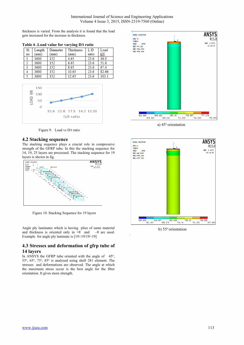
thickness is varied. From the analysis it is found that the load
gets increased for the increase in thickness.
Table 6 .Load value for varying D/t ratio
Figure 9. Load vs D/t ratio
4.2 Stacking sequence The stacking sequence plays a crucial role in compressive
strength of the GFRP tube. In this the stacking sequence for
14, 19, 25 layers are processed. The stacking sequence for 19
layers is shown in fig.
Figure 10. Stacking Sequence for 19 layers
Angle ply laminates which is having plies of same material
and thickness is oriented only in +θ and –θ are used.
Example for angle ply laminate is [19/-19/19/-19]
4.3 Stresses and deformation of gfrp tube of
14 layers In ANSYS the GFRP tube oriented with the angle of 45o,
55o, 65o, 75o, 85o is analysed using shell 281 element. The
stresses and deformations are observed. The angle at which
the maximum stress occur is the best angle for the fiber
orientation. It gives more strength.
a) 45o orientation
b) 55o orientation .

International Journal of Science and Engineering Applications
Volume 4 Issue 3, 2015, ISSN-2319-7560 (Online)
www.ijsea.com 114
C) 65o orientation
d) 75o orientation
e) 85o orientation
Table7. Stress And Deformation For 14 layers
Figure 11. Stress vs orientation (14 layers)
4.4 Stresses and deformation of GFRP tube
of 19 layers
a) 45o orientation

International Journal of Science and Engineering Applications
Volume 4 Issue 3, 2015, ISSN-2319-7560 (Online)
www.ijsea.com 115
b) 55o orientation
C) 65o orientation
d) 75o orientation
.
e) 85o orientation
Table 8.Stress And Deformation For 19 Layers
Figure 12 . Stress vs orientation (19 layers)
International Journal of Science and Engineering Applications
Volume 4 Issue 3, 2015, ISSN-2319-7560 (Online)
www.ijsea.com 116
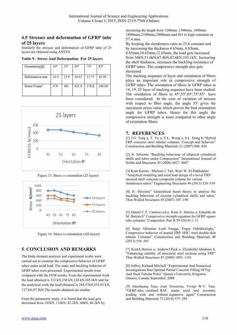
4.5 Stresses and deformation of GFRP tube
of 25 layers Similarly the stresses and deformation of GFRP tube of 25
layers are obtained using ANSYS.
Table 9 . Stress And Deformation For 25 layers
Figure 13. Stress vs orientation (25 layers)
0
200
400
600
800
1000
45 55 65 75 85
Stre
ss N
/mm
2
Orientation θo
14 layers
19 layers
25 layers
Figure 14. Stress vs orientation (All layers)
5. CONCLUSION AND REMARKS
The finite element analyses and experiment works were
carried out to examine the compressive behavior of GFRP
tubes under axial load. The static and buckling behavior of
GFRP tubes were processed. Experimental results were
compared with the FEM results. From the experimental work
the load obtained is 312 kN,336 kN,124 kN,105.6kN and for
the analytical work the load obtained is 284.57kN,353.65 kN,
137 kN,97.3kN.The results obtained are similar.
From the parametric study, it is found that the load gets
decreased from 185kN, 118kN, 82.2kN, 60kN, 46.2kN by
increasing the length from 1200mm ,1500mm, 1800mm
1800mm,2100mm,2400mm and D/t is kept constant as
57.4 mm.
By keeping the slenderness ratio as 23.6 constant and
by increasing the thickness 4.65mm, 6.65mm,
8.65mm,10.65mm,12.65mm, the load gets increased
from 36kN,51.6kN,67.4kN,82.6kN,103.1kN. Increasing
the shell thickness, increases the buckling resistance of
GFRP tubes .The compressive strength also gets
increased.
The stacking sequence of layer and orientation of fibers
plays an important role in compressive strength of
GFRP tubes. The orientation of fibers in GFRP tubes in
14, 19, 25 layer of stacking sequence have been studied.
The orientation of fibers in 45o,55o,65o,75o,85o have
been considered. In the case of variation of stresses
with respect to fiber angle, the angle 55o gives the
maximum stress value which proves the best orientation
angle for GFRP tubes. Hence for this angle the
compressive strength is more compared to other angle
of orientation fibers.
7. REFERENCES [1] J.G. Teng a, T. Yu a, Y.L. Wong a, S.L. Dong b,“Hybrid
FRP–concrete–steel tubular columns: Concept and behavior”
Construction and Building Materials 21 (2007) 846–854
[2] N. Silvestre “Buckling behaviour of elliptical cylindrical
shells and tubes under Compression” International Journal of
Solids and Structures 45 (2008) 4427–4447
[3] Kian Karimi , Michael J. Tait, Wael W. El-Dakhakhni
“Analytical modeling and axial load design of a novel FRP-
encased steel–concrete composite column for various
slenderness ratios” Engineering Structures 46 (2013) 526–534
[4] N. Silvestre” Generalised beam theory to analyse the
buckling behaviour of circular cylindrical shells and tubes”
Thin-Walled Structures 45 (2007) 185–198
[5] Daniel C.T. Cardoso a,b,c, Kent A. Harries a, Eduardo de
M. Batista b” Compressive strength equation for GFRP square
tube columns” Composites: Part B 59 (2014) 1–11
[6] Butje Alfonsius Louk Fanggi, Togay Ozbakkaloglu,”
Compressive behavior of aramid FRP–HSC–steel double-skin
tubular Columns” Construction and Building Materials 48
(2013) 554–565
[7] KentA.Harries a, AndrewJ.Peck a, ElizabethJ.Abraham b,
”Enhancing stability of structural steel sections using FRP”
Thin-Walled Structures 47 (2009) 1092–1101
[8] Jeffrey Richard Mitchell “Experimental And Numerical
Investigations Into Optimal Partial Concrete Filling Of Frp
And Steel Tubular Poles” Queen’s University Kingston,
Ontario, Canada September, 2008
[9] Jianzhuang Xiao, Joan Tresserras, Vivian W.Y. Tam,
“GFRP-tube confined RAC under axial and eccentric
loading with and without expansive agent” Construction
and Building Materials 73 (2014) 575–585