handbook of plas cs failure analysis - hanser publications · handbook of plas cs failure analysis...
TRANSCRIPT
Handbook ofPlas cs Failure Analysis
Friedrich Kurr
Book ISBN978-1-56990-519-7
e-Book ISBN978-1-56990-545-6
HANSER Hanser Publishers, Munich • Hanser Publica ons, Cincinna
Table of Contents, Author’s Preface, Sample Pages: Glossary, Defi nitions, Figures & Text
V
Table of Contents
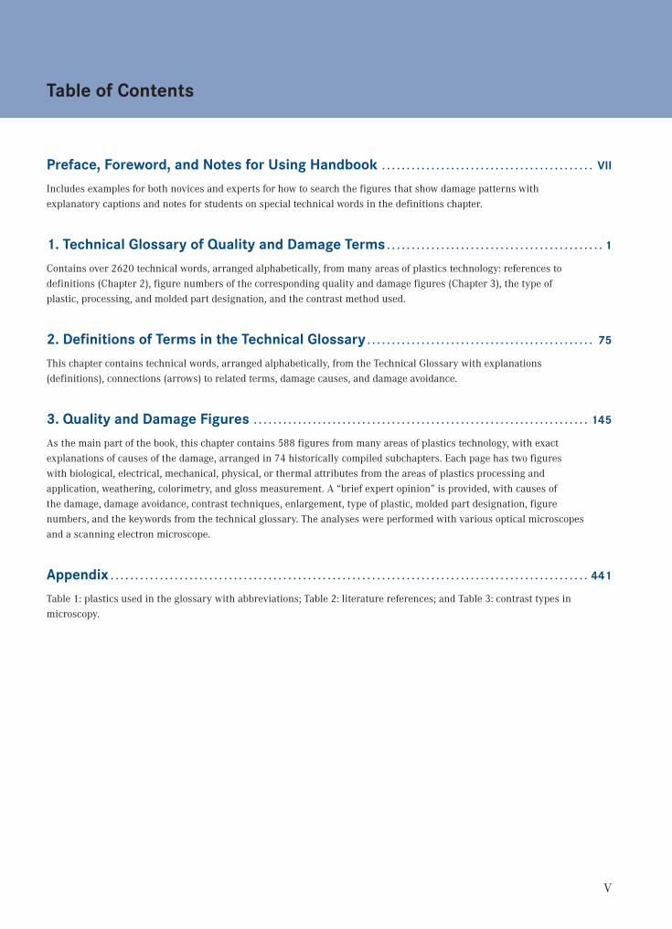
Preface, Foreword, and Notes for Using Handbook . . . . . . . . . . . . . . . . . . . . . . . . . . . . . . . . . . . . . . . . . . . VII
Includes examples for both novices and experts for how to search the figures that show damage patterns with explanatory captions and notes for students on special technical words in the definitions chapter.
1. Technical Glossary of Quality and Damage Terms . . . . . . . . . . . . . . . . . . . . . . . . . . . . . . . . . . . . . . . . . . . . 1
Contains over 2620 technical words, arranged alphabetically, from many areas of plastics technology: references to definitions (Chapter 2), figure numbers of the corresponding quality and damage figures (Chapter 3), the type of plastic, processing, and molded part designation, and the contrast method used.
2. Definitions of Terms in the Technical Glossary . . . . . . . . . . . . . . . . . . . . . . . . . . . . . . . . . . . . . . . . . . . . . . 75
This chapter contains technical words, arranged alphabetically, from the Technical Glossary with explanations (definitions), connections (arrows) to related terms, damage causes, and damage avoidance.
3. Quality and Damage Figures . . . . . . . . . . . . . . . . . . . . . . . . . . . . . . . . . . . . . . . . . . . . . . . . . . . . . . . . . . . . . . . . . . . . 145
As the main part of the book, this chapter contains 588 figures from many areas of plastics technology, with exact explanations of causes of the damage, arranged in 74 historically compiled subchapters. Each page has two figures with biological, electrical, mechanical, physical, or thermal attributes from the areas of plastics processing and application, weathering, colorimetry, and gloss measurement. A “brief expert opinion” is provided, with causes of the damage, damage avoidance, contrast techniques, enlargement, type of plastic, molded part designation, figure numbers, and the keywords from the technical glossary. The analyses were performed with various optical microscopes and a scanning electron microscope.
Appendix . . . . . . . . . . . . . . . . . . . . . . . . . . . . . . . . . . . . . . . . . . . . . . . . . . . . . . . . . . . . . . . . . . . . . . . . . . . . . . . . . . . . . . . . . . . . . . . . . 441
Table 1: plastics used in the glossary with abbreviations; Table 2: literature references; and Table 3: contrast types in microscopy.
VII
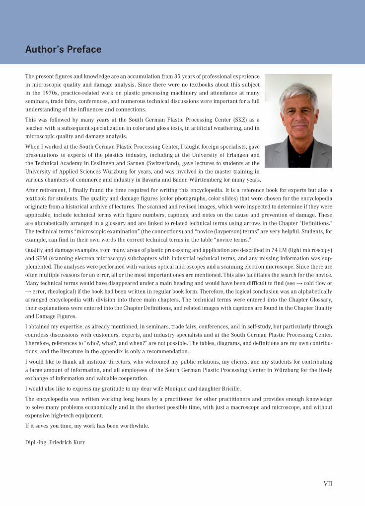
Author’s Preface
The present figures and knowledge are an accumulation from 35 years of professional experience in microscopic quality and damage analysis. Since there were no textbooks about this subject in the 1970s, practice-related work on plastic processing machinery and attendance at many seminars, trade fairs, conferences, and numerous technical discussions were important for a full understanding of the influences and connections.
This was followed by many years at the South German Plastic Processing Center (SKZ) as a teacher with a subsequent specialization in color and gloss tests, in artificial weathering, and in microscopic quality and damage analysis.
When I worked at the South German Plastic Processing Center, I taught foreign specialists, gave presentations to experts of the plastics industry, including at the University of Erlangen and the Technical Academy in Esslingen and Sarnen (Switzerland), gave lectures to students at the University of Applied Sciences Würzburg for years, and was involved in the master training in various chambers of commerce and industry in Bavaria and Baden-Württemberg for many years.
After retirement, I finally found the time required for writing this encyclopedia. It is a reference book for experts but also a textbook for students. The quality and damage figures (color photographs, color slides) that were chosen for the encyclopedia originate from a historical archive of lectures. The scanned and revised images, which were inspected to determine if they were applicable, include technical terms with figure numbers, captions, and notes on the cause and prevention of damage. These are alphabetically arranged in a glossary and are linked to related technical terms using arrows in the Chapter “Definitions.” The technical terms “microscopic examination” (the connections) and “novice (layperson) terms” are very helpful. Students, for example, can find in their own words the correct technical terms in the table “novice terms.”
Quality and damage examples from many areas of plastic processing and application are described in 74 LM (light microscopy) and SEM (scanning electron microscopy) subchapters with industrial technical terms, and any missing information was sup-plemented. The analyses were performed with various optical microscopes and a scanning electron microscope. Since there are often multiple reasons for an error, all or the most important ones are mentioned. This also facilitates the search for the novice. Many technical terms would have disappeared under a main heading and would have been difficult to find (see → cold flow or → error, rheological) if the book had been written in regular book form. Therefore, the logical conclusion was an alphabetically arranged encyclopedia with division into three main chapters. The technical terms were entered into the Chapter Glossary, their explanations were entered into the Chapter Definitions, and related images with captions are found in the Chapter Quality and Damage Figures.
I obtained my expertise, as already mentioned, in seminars, trade fairs, conferences, and in self-study, but particularly through countless discussions with customers, experts, and industry specialists and at the South German Plastic Processing Center. Therefore, references to “who?, what?, and when?” are not possible. The tables, diagrams, and definitions are my own contribu-tions, and the literature in the appendix is only a recommendation.
I would like to thank all institute directors, who welcomed my public relations, my clients, and my students for contributing a large amount of information, and all employees of the South German Plastic Processing Center in Würzburg for the lively exchange of information and valuable cooperation.
I would also like to express my gratitude to my dear wife Monique and daughter Bricille.
The encyclopedia was written working long hours by a practitioner for other practitioners and provides enough knowledge to solve many problems economically and in the shortest possible time, with just a macroscope and microscope, and without expensive high-tech equipment.
If it saves you time, my work has been worthwhile.
Dipl.-Ing. Friedrich Kurr

1
Chapter 1
Technical Glossary of Quality and Damage Terms
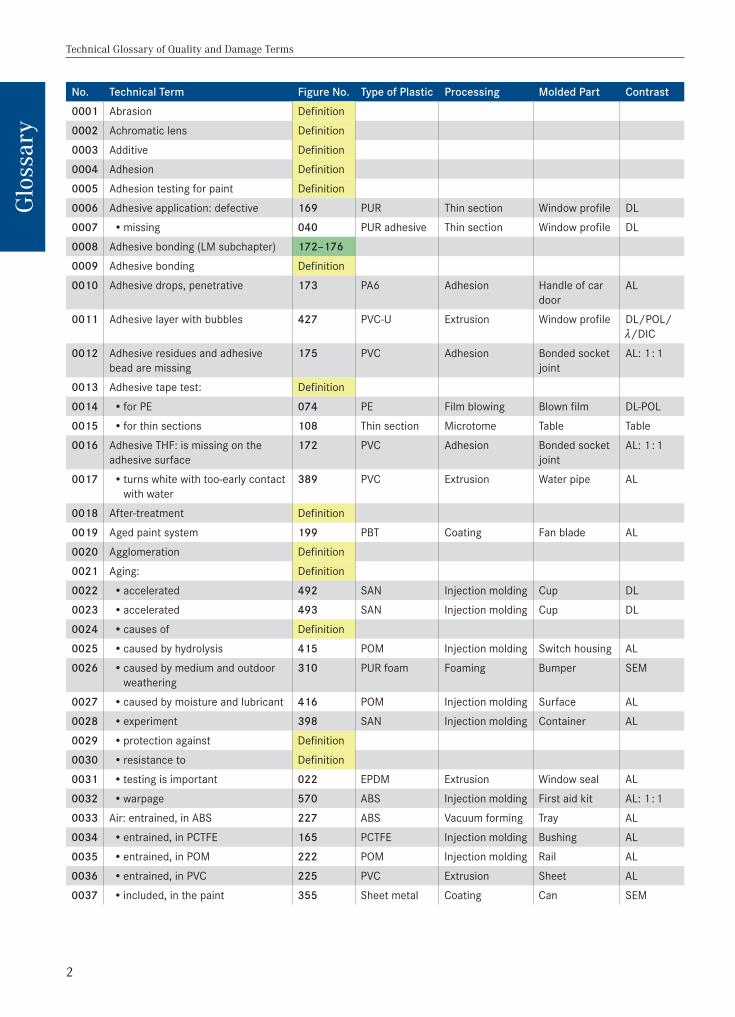
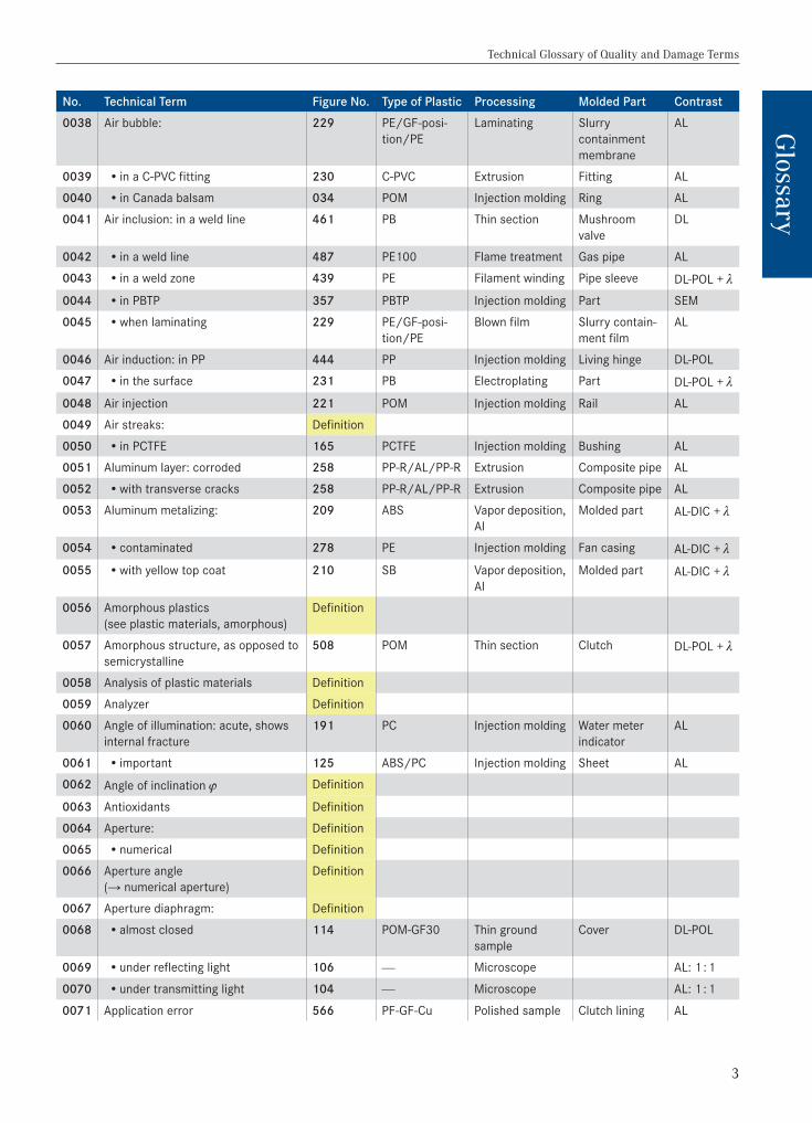
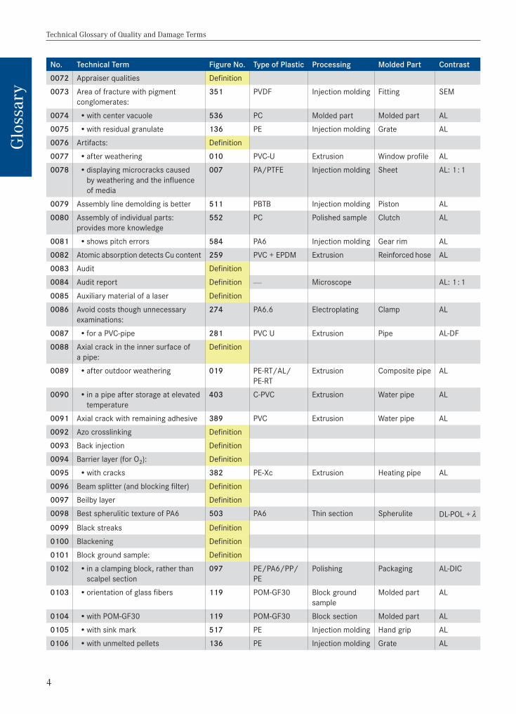
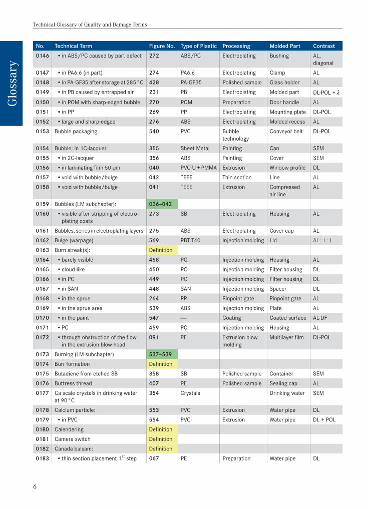
This chapter includes over 2620 alphabetically arranged technical terms from many areas of plastic technology with references to definitions, figure numbers of the corresponding quality and damage figures, the type of plastic, processing, and mold designation, the contrasting methods used, and 74 LM and SEM subchapters (see the first page of the Chapter Quality and Damage Figures). Since there are often multiple reasons for an error, all or the most important ones are mentioned. This facilitates the search.
The numbers after the technical terms are figure numbers, and the associated figures with explanatory text are located in the Chapter Quality and Damage Figures. There the search is implemented with the figure numbers from the technical glossary or directly in the LM and SEM subchapters.
Double numbers are located after LM or SEM subchapters (for example, figure numbers 307–311 means SEM subchapter weath-ering with five figures). The subchapters originate from a historical archive collection that took decades to amass.
The yellow-colored cell “definition” in the column “Figure No.” refers to an explanation of the technical term in the Chapter Definitions (where many technical terms are explained).
Students will find a quick introduction to the subject through “→ Novice terms” and “→ Microscopic examination” in the Chapter Definitions. They are the source of cross references with arrows through the entire encyclopedia.
For the technical terms, the associated figure numbers are found in the Chapter Glossary and the associated figures are in the Chapter Quality and Damage Figures.
Experts will find the figure with caption through a technical term and the following figure number in the Chapter Quality and Damage Figures in the Chapter Glossary. An explanation of the technical term can also be found in the Chapter Definitions, if desired.
Explanation of color coding used in Column 3 in the Chapter Glossary:
Color coding Explanation Thumb Index
Technical terms, arranged alphabetically in the Chapter Glossary Glossary
Figure numbers from 1 to 588, arranged in the Chapter Quality and Damage Figures Figures & Text
LM subchapter with figure captions in the Chapter Quality and Damage Figures Figures & Text
SEM subchapter with figure captions in the Chapter Quality and Damage Figures Figures & Text
Explanation of the technical terms from the Chapter Glossary in Chapter Definitions Definitions
LM = Light microscopy (or light microscope) SEM = Scanning electron microscopy (or scanning electron microscope)
For search examples, see pages X–XII.
Technical Glossary of Quality and Damage Terms
2
Glo
ssar
y
No. Technical Term Figure No. Type of Plastic Processing Molded Part Contrast0001 Abrasion Definition0002 Achromatic lens Definition0003 Additive Definition0004 Adhesion Definition0005 Adhesion testing for paint Definition0006 Adhesive application: defective 169 PUR Thin section Window profile DL0007 •missing 040 PUR adhesive Thin section Window profile DL0008 Adhesive bonding (LM subchapter) 172–1760009 Adhesive bonding Definition0010 Adhesive drops, penetrative 173 PA6 Adhesion Handle of car
doorAL
0011 Adhesive layer with bubbles 427 PVC-U Extrusion Window profile DL/POL/ /DIC
0012 Adhesive residues and adhesive bead are missing
175 PVC Adhesion Bonded socket joint
AL: 1 : 1
0013 Adhesive tape test: Definition0014 • for PE 074 PE Film blowing Blown film DL-POL0015 • for thin sections 108 Thin section Microtome Table Table0016 Adhesive THF: is missing on the
adhesive surface172 PVC Adhesion Bonded socket
jointAL: 1 : 1
0017 • turns white with too-early contact with water
389 PVC Extrusion Water pipe AL
0018 After-treatment Definition0019 Aged paint system 199 PBT Coating Fan blade AL0020 Agglomeration Definition0021 Aging: Definition0022 •accelerated 492 SAN Injection molding Cup DL0023 •accelerated 493 SAN Injection molding Cup DL0024 •causes of Definition0025 •caused by hydrolysis 415 POM Injection molding Switch housing AL0026 •caused by medium and outdoor
weathering 310 PUR foam Foaming Bumper SEM
0027 •caused by moisture and lubricant 416 POM Injection molding Surface AL0028 •experiment 398 SAN Injection molding Container AL0029 •protection against Definition0030 • resistance to Definition0031 • testing is important 022 EPDM Extrusion Window seal AL0032 •warpage 570 ABS Injection molding First aid kit AL: 1 : 10033 Air: entrained, in ABS 227 ABS Vacuum forming Tray AL0034 •entrained, in PCTFE 165 PCTFE Injection molding Bushing AL0035 •entrained, in POM 222 POM Injection molding Rail AL0036 •entrained, in PVC 225 PVC Extrusion Sheet AL0037 • included, in the paint 355 Sheet metal Coating Can SEM
Technical Glossary of Quality and Damage Terms
3
Glossary
No. Technical Term Figure No. Type of Plastic Processing Molded Part Contrast0038 Air bubble: 229 PE/GF-posi-
tion/PELaminating Slurry
contain ment membrane
AL
0039 • in a C-PVC fitting 230 C-PVC Extrusion Fitting AL0040 • in Canada balsam 034 POM Injection molding Ring AL0041 Air inclusion: in a weld line 461 PB Thin section Mushroom
valveDL
0042 • in a weld line 487 PE100 Flame treatment Gas pipe AL0043 • in a weld zone 439 PE Filament winding Pipe sleeve DL-POL + 0044 • in PBTP 357 PBTP Injection molding Part SEM0045 •when laminating 229 PE/GF-posi-
tion/PEBlown film Slurry contain-
ment filmAL
0046 Air induction: in PP 444 PP Injection molding Living hinge DL-POL0047 • in the surface 231 PB Electroplating Part DL-POL + 0048 Air injection 221 POM Injection molding Rail AL0049 Air streaks: Definition0050 • in PCTFE 165 PCTFE Injection molding Bushing AL0051 Aluminum layer: corroded 258 PP-R/AL/PP-R Extrusion Composite pipe AL0052 •with transverse cracks 258 PP-R/AL/PP-R Extrusion Composite pipe AL0053 Aluminum metalizing: 209 ABS Vapor deposition,
AlMolded part AL-DIC +
0054 •contaminated 278 PE Injection molding Fan casing AL-DIC + 0055 •with yellow top coat 210 SB Vapor deposition,
AlMolded part AL-DIC +
0056 Amorphous plastics (see plastic materials, amorphous)
Definition
0057 Amorphous structure, as opposed to semicrystalline
508 POM Thin section Clutch DL-POL +
0058 Analysis of plastic materials Definition0059 Analyzer Definition0060 Angle of illumination: acute, shows
internal fracture 191 PC Injection molding Water meter
indicatorAL
0061 • important 125 ABS/PC Injection molding Sheet AL0062 Angle of inclination j Definition
0063 Antioxidants Definition0064 Aperture: Definition0065 •numerical Definition0066 Aperture angle
(→ numerical aperture) Definition
0067 Aperture diaphragm: Definition0068 •almost closed 114 POM-GF30 Thin ground
sampleCover DL-POL
0069 •under reflecting light 106 — Microscope AL: 1 : 1
0070 •under transmitting light 104 — Microscope AL: 1 : 1
0071 Application error 566 PF-GF-Cu Polished sample Clutch lining AL
Technical Glossary of Quality and Damage Terms
4
Glo
ssar
y
No. Technical Term Figure No. Type of Plastic Processing Molded Part Contrast0072 Appraiser qualities Definition0073 Area of fracture with pigment
conglomerates:351 PVDF Injection molding Fitting SEM
0074 •with center vacuole 536 PC Molded part Molded part AL0075 •with residual granulate 136 PE Injection molding Grate AL0076 Artifacts: Definition0077 •after weathering 010 PVC-U Extrusion Window profile AL0078 •displaying microcracks caused
by weathering and the influence of media
007 PA/PTFE Injection molding Sheet AL: 1 : 1
0079 Assembly line demolding is better 511 PBTB Injection molding Piston AL0080 Assembly of individual parts:
provides more knowledge 552 PC Polished sample Clutch AL
0081 •shows pitch errors 584 PA6 Injection molding Gear rim AL0082 Atomic absorption detects Cu content 259 PVC + EPDM Extrusion Reinforced hose AL0083 Audit Definition0084 Audit report Definition — Microscope AL: 1 : 1
0085 Auxiliary material of a laser Definition0086 Avoid costs though unnecessary
examinations: 274 PA6.6 Electroplating Clamp AL
0087 • for a PVC-pipe 281 PVC U Extrusion Pipe AL-DF0088 Axial crack in the inner surface of
a pipe:Definition
0089 •after outdoor weathering 019 PE-RT/AL/PE-RT
Extrusion Composite pipe AL
0090 • in a pipe after storage at elevated temperature
403 C-PVC Extrusion Water pipe AL
0091 Axial crack with remaining adhesive 389 PVC Extrusion Water pipe AL0092 Azo crosslinking Definition0093 Back injection Definition0094 Barrier layer (for O2): Definition0095 •with cracks 382 PE-Xc Extrusion Heating pipe AL0096 Beam splitter (and blocking filter) Definition0097 Beilby layer Definition0098 Best spherulitic texture of PA6 503 PA6 Thin section Spherulite DL-POL + 0099 Black streaks Definition0100 Blackening Definition0101 Block ground sample: Definition0102 • in a clamping block, rather than
scalpel section 097 PE/PA6/PP/
PEPolishing Packaging AL-DIC
0103 •orientation of glass fibers 119 POM-GF30 Block ground sample
Molded part AL
0104 •with POM-GF30 119 POM-GF30 Block section Molded part AL0105 •with sink mark 517 PE Injection molding Hand grip AL0106 •with unmelted pellets 136 PE Injection molding Grate AL

Technical Glossary of Quality and Damage Terms
5
Glossary
No. Technical Term Figure No. Type of Plastic Processing Molded Part Contrast0107 Block section: Definition0108 •with PBT/PC 561 PBT/PC Block section Housing AL-DF0109 Blocking filter Definition0110 Blowholes (LM-subchapter) 221–2300111 Blowholes (SEM-subchapter) 357–357 SEM0112 Blowholes: Definition0113 • in a deep-drawn part 228 ABS Vacuum forming Tray AL0114 • in ABS 225 ABS Extrusion Blend AL0115 • in an ABS blend 226 ABS Injection molding Blend AL0116 • in C-PVC 230 C-PVC Extrusion Fitting AL0117 • in PBTP 357 PBTP Injection molding Molded part SEM0118 • in POM 221 POM Injection molding Rail AL0119 • in POM 222 POM Polished sample Rail AL0120 • in PVC 224 PVC Extrusion Sheet AL0121 • through residual moisture 223 PVC Extrusion Sheet AL0122 • through thermal decomposition 228 ABS Vacuum forming Tray AL0123 •when extruding 226 ABS Injection molding Blend AL0124 Blow molding Definition0125 Blow molding of hollow objects Definition0126 Blown film: 3-layered 229 PE/GF-layer/
PEBlown film Slurry film AL
0127 •coextruded 085 PE Coextrusion Carrying bag AL0128 Bridge marking for: HDPE 445 HDPE Extrusion Sewer pipe DL0129 •PE-X 454 PE-X Extrusion Pipe DL0130 Bridges with: ring binding 032 POM Injection molding Bridge ring AL0131 •weld lines 032 POM Injection molding Bridge ring AL0132 Bright field contrast AL-HF and DL-HF Definition0133 Bright field dark field slider 105 — Microscope AL: 1 : 1
0134 Brittle cracks in roof and welded sheets after outdoor weathering
309 Polymer Extrusion Bituminous sheeting
SEM
0135 Brittle fracture: in ASA 413 ASA Extrusion Sheet AL + DL0136 • in PE 319 PE Injection molding Rod SEM0137 Brittle molded part cross-section 508 POM Thin section Clutch DL-POL + 0138 Bubble formation: Definition0139 •electroplating bubble, opened by
scalpel270 POM Electroplating Door handle AL
0140 •electroplating bubble, sharp-edged 271 POM Electroplating Door handle AL0141 •electroplating bubble, sharp-edged 275 ABS Electroplating Cover cap AL0142 • in ABS 265 ABS Electroplating Cover AL0143 • in ABS 266 ABS Electroplating Cover AL0144 • in ABS 267 ABS Electroplating Cover AL0145 • in ABS with large sharp-edged
bubble 276 ABS Electroplating Molded recess AL
Technical Glossary of Quality and Damage Terms
6
Glo
ssar
y
No. Technical Term Figure No. Type of Plastic Processing Molded Part Contrast0146 • in ABS/PC caused by part defect 272 ABS/PC Electroplating Bushing AL,
diagonal0147 • in PA6.6 (in part) 274 PA6.6 Electroplating Clamp AL0148 • in PA-GF35 after storage at 285 °C 428 PA-GF35 Polished sample Glass holder AL0149 • in PB caused by entrapped air 231 PB Electroplating Molded part DL-POL + 0150 • in POM with sharp-edged bubble 270 POM Preparation Door handle AL0151 • in PP 269 PP Electroplating Mounting plate DL-POL0152 • large and sharp-edged 276 ABS Electroplating Molded recess AL0153 Bubble packaging 540 PVC Bubble
technologyConveyor belt DL-POL
0154 Bubble: in 1C-lacquer 355 Sheet Metal Painting Can SEM0155 • in 2C-lacquer 356 ABS Painting Cover SEM0156 • in laminating film 50 µm 040 PVC-U + PMMA Extrusion Window profile DL0157 •void with bubble/bulge 042 TEEE Thin section Line AL0158 •void with bubble/bulge 041 TEEE Extrusion Compressed
air lineAL
0159 Bubbles (LM subchapter): 036–0420160 •visible after stripping of electro-
plating coats 273 SB Electroplating Housing AL
0161 Bubbles, series in electroplating layers 275 ABS Electroplating Cover cap AL0162 Bulge (warpage) 569 PBT T40 Injection molding Lid AL: 1 : 10163 Burn streak(s): Definition0164 •barely visible 458 PC Injection molding Housing AL0165 •cloud-like 450 PC Injection molding Filter housing DL0166 • in PC 449 PC Injection molding Filter housing DL0167 • in SAN 448 SAN Injection molding Spacer DL0168 • in the sprue 264 PP Pinpoint gate Pinpoint gate AL0169 • in the sprue area 539 ABS Injection molding Plate AL0170 • in the paint 547 — Coating Coated surface AL-DF
0171 •PC 459 PC Injection molding Housing AL0172 • through obstruction of the flow
in the extrusion blow head091 PE Extrusion blow
moldingMultilayer film DL-POL
0173 Burning (LM subchapter) 537–5390174 Burr formation Definition0175 Butadiene from etched SB 358 SB Polished sample Container SEM0176 Buttress thread 407 PE Polished sample Sealing cap AL0177 Ca scale crystals in drinking water
at 90 °C 354 Crystals Drinking water SEM
0178 Calcium particle: 553 PVC Extrusion Water pipe DL0179 • in PVC 554 PVC Extrusion Water pipe DL + POL0180 Calendering Definition0181 Camera switch Definition0182 Canada balsam: Definition0183 • thin section placement 1st step 067 PE Preparation Water pipe DL
75
Chapter 2
Definition of Terms in the Technical Glossary
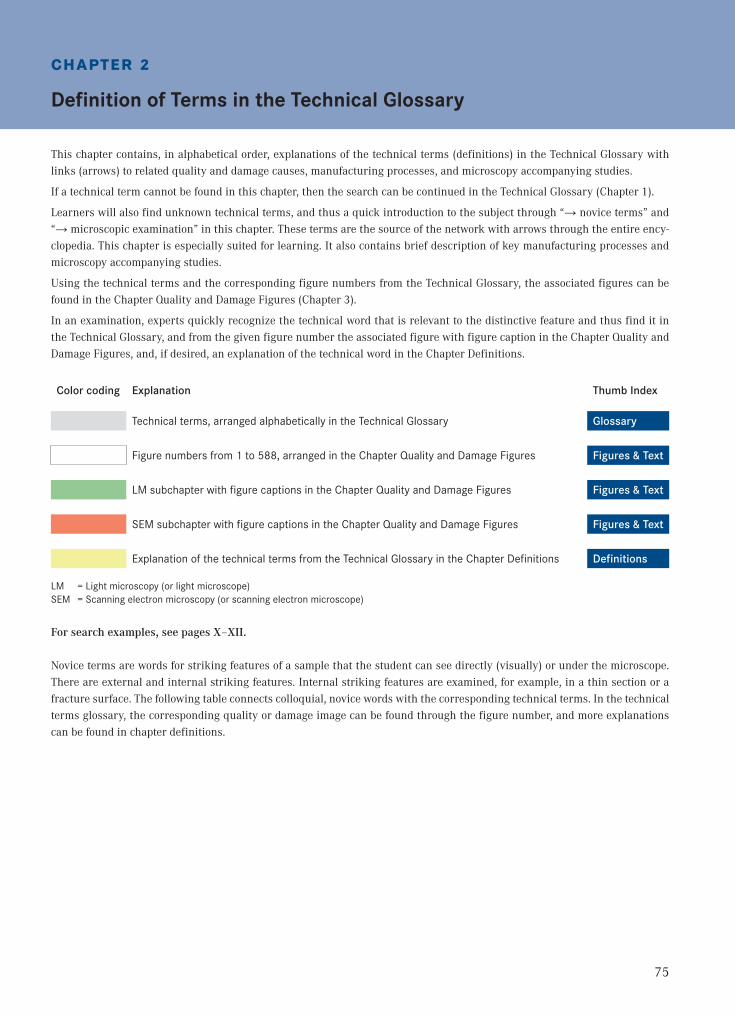
This chapter contains, in alphabetical order, explanations of the technical terms (definitions) in the Technical Glossary with links (arrows) to related quality and damage causes, manufacturing processes, and microscopy accompanying studies.
If a technical term cannot be found in this chapter, then the search can be continued in the Technical Glossary (Chapter 1).
Learners will also find unknown technical terms, and thus a quick introduction to the subject through “→ novice terms” and “→ microscopic examination” in this chapter. These terms are the source of the network with arrows through the entire ency-clopedia. This chapter is especially suited for learning. It also contains brief description of key manufacturing processes and microscopy accompanying studies.
Using the technical terms and the corresponding figure numbers from the Technical Glossary, the associated figures can be found in the Chapter Quality and Damage Figures (Chapter 3).
In an examination, experts quickly recognize the technical word that is relevant to the distinctive feature and thus find it in the Technical Glossary, and from the given figure number the associated figure with figure caption in the Chapter Quality and Damage Figures, and, if desired, an explanation of the technical word in the Chapter Definitions.
Color coding Explanation Thumb Index
Technical terms, arranged alphabetically in the Technical Glossary Glossary
Figure numbers from 1 to 588, arranged in the Chapter Quality and Damage Figures Figures & Text
LM subchapter with figure captions in the Chapter Quality and Damage Figures Figures & Text
SEM subchapter with figure captions in the Chapter Quality and Damage Figures Figures & Text
Explanation of the technical terms from the Technical Glossary in the Chapter Definitions Definitions
LM = Light microscopy (or light microscope) SEM = Scanning electron microscopy (or scanning electron microscope)
For search examples, see pages X–XII.
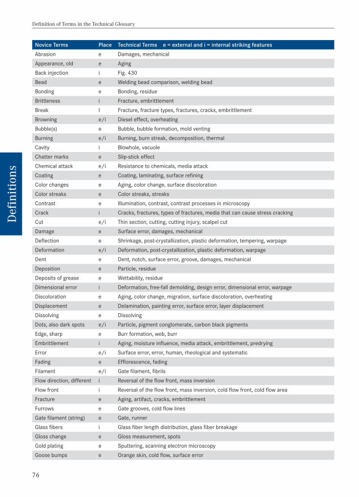
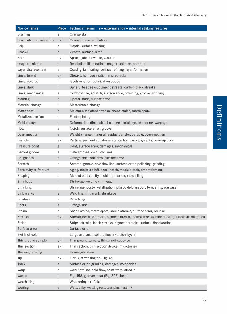
Novice terms are words for striking features of a sample that the student can see directly (visually) or under the microscope. There are external and internal striking features. Internal striking features are examined, for example, in a thin section or a fracture surface. The following table connects colloquial, novice words with the corresponding technical terms. In the technical terms glossary, the corresponding quality or damage image can be found through the figure number, and more explanations can be found in chapter definitions.
76
Definition of Terms in the Technical Glossary
Def
initi
ons
Novice Terms Place Technical Terms e = external and i = internal striking featuresAbrasion e Damages, mechanicalAppearance, old e Aging Back injection i Fig. 430 Bead e Welding bead comparison, welding beadBonding e Bonding, residueBrittleness i Fracture, embrittlementBreak I Fracture, fracture types, fractures, cracks, embrittlementBrowning e/i Diesel effect, overheatingBubble(s) e Bubble, bubble formation, mold venting Burning e/i Burning, burn streak, decomposition, thermal Cavity i Blowhole, vacuole Chatter marks e Slip-stick effect Chemical attack e/i Resistance to chemicals, media attack Coating e Coating, laminating, surface refiningColor changes e Aging, color change, surface discolorationColor streaks e Color streaks, streaks Contrast e Illumination, contrast, contrast processes in microscopyCrack i Cracks, fractures, types of fractures, media that can cause stress crackingCut e/i Thin section, cutting, cutting injury, scalpel cut Damage e Surface error, damages, mechanical Deflection e Shrinkage, post-crystallization, plastic deformation, tempering, warpageDeformation e/i Deformation, post-crystallization, plastic deformation, warpageDent e Dent, notch, surface error, groove, damages, mechanicalDeposition e Particle, residue Deposits of grease e Wettability, residueDimensional error i Deformation, free-fall demolding, design error, dimensional error, warpageDiscoloration e Aging, color change, migration, surface discoloration, overheatingDisplacement e Delamination, painting error, surface error, layer displacementDissolving e DissolvingDots, also dark spots e/i Particle, pigment conglomerate, carbon black pigmentsEdge, sharp e Burr formation, web, burrEmbrittlement i Aging, moisture influence, media attack, embrittlement, predrying Error e/i Surface error, error, human, rheological and systematic Fading e Efflorescence, fadingFilament e/i Gate filament, fibrils Flow direction, different i Reversal of the flow front, mass inversion Flow front i Reversal of the flow front, mass inversion, cold flow front, cold flow area Fracture e Aging, artifact, cracks, embrittlementFurrows e Gate grooves, cold flow linesGate filament (string) e Gate, runnerGlass fibers i Glass fiber length distribution, glass fiber breakageGloss change e Gloss measurement, spotsGold plating e Sputtering, scanning electron microscopyGoose bumps e Orange skin, cold flow, surface error
77
Definition of Terms in the Technical Glossary
Definitions
Novice Terms Place Technical Terms e = external and i = internal striking featuresGraining e Orange skin Granulate contamination e/i Granulate contaminationGrip e Haptic, surface refiningGroove e Groove, surface errorHole e/i Sprue, gate, blowhole, vacuole Image resolution e Resolution, illumination, image resolution, contrastLayer displacement e Coating, laminating, surface refining, layer formation Lines, bright e/i Streaks, homogenization, microcracks Lines, colored i Isochromatics, polarization optics Lines, dark i Spherulite streaks, pigment streaks, carbon black streaks Lines, mechanical e Coldflow line, scratch, surface error, polishing, groove, grindingMarking e Ejector mark, surface error Material change i Masterbatch changeMatte spot e Moisture, moisture streaks, shape stains, matte spotsMetallized surface e ElectroplatingMold change e Deformation, dimensional change, shrinkage, tempering, warpageNotch e Notch, surface error, grooveOver-injection e Weight change, material residue transfer, particle, over-injectionParticle e/i Particle, pigment conglomerate, carbon black pigments, over-injectionPressure point e Dent, surface error, damages, mechanical Record groove e Gate grooves, cold flow lines Roughness e Orange skin, cold flow, surface errorScratch e Scratch, groove, cold flow line, surface error, polishing, grindingSensitivity to fracture i Aging, moisture influence, notch, media attack, embrittlementShaping e Molded part quality, mold impression, mold fillingShrinkage i Shrinkage, volume shrinkage Shrinking i Shrinkage, post-crystallization, plastic deformation, tempering, warpage Sink marks e Weld line, sink mark, shrinkageSolution e DissolvingSpots e Orange skin Stains e Shape stains, matte spots, media streaks, surface error, residue Streaks e/i Streaks, hot-cold streaks, pigment streaks, thermal streaks, burn streaks, surface discolorationStrips e Strips, streaks, black streaks, pigment streaks, surface discolorationSurface error e Surface errorSwirls of color i Large and small spherulites, inversion layersThin ground sample e/i Thin ground sample, thin grinding deviceThin section e/i Thin section, thin section device (microtome) Thorough mixing i HomogenizationTip e/i Fibrils, stretching tip (Fig. 46)Track e Surface error, grinding, damages, mechanical Warp e Cold flow line, cold flow, paint warp, streaksWaves i Fig. 458, grooves, tear (Fig. 322), beadWeathering e Weathering, artificial Wetting e Wettability, wetting test, test pins, test ink

78
Definition of Terms in the Technical Glossary Abrasion
Def
initi
ons
Technical Terms Explanation of Terms Abrasion Abrasion is surface wear, for example due to reinforcing materials in the screw and in the cylinder
(see also → glass fibers). Achromatic lens In an achromatic lens, the objective is corrected in the two colors, red and blue, so that both will be
reflected in the focal plane without distortion (see also → Neofluar lenses, → objective, and → plan apochromatic objective).
Additive Additives are added to plastics to improve their properties and service life (aging). Additives include antioxidants (inhibitors, light stabilizers, fire protection equipment, radiation protection, UV stabilizers, heat stabilizers), filler materials (nanofillers, glass fibers, kaolin, chalk, magnesia, sand), lubricants, and nucleating or reinforcing materials (see also → antioxidants, → fire prevention equipment, → filler materials and reinforcing materials, → GC analysis, → glass fibers, → lubricants, → HPLC analysis, → inhibitors, → IR analysis, → analysis of plastic materials, → light stabilizers, → nanofillers, → nucle-ating agents, → radiation protection, → UV spectroscopy, → UV stabilizers, → reinforcing materials, and → heat stabilizers).
Adhesion Diffusion-based acrylic adhesives have particularly proven their worth for adhesion of thin ground samples onto glass slides. Depending on the sample hardness and requirements, EP and UP resins with and without filler materials are also used. A sample glued with a diffusion-based acrylic adhesive can be carefully removed with a preparation needle from the glass slide after 10 minutes immersion in ethanol. Many plastics have adequate resistance. Then the exposed thin ground sample is fixed onto a glass slide with Canada balsam or Eukitt and is covered with a cover glass. This is how clean thin ground samples can be manufactured in thin section quality, without air bubbles, peeling places, and coolant back migration (see also → thin grinding device and → adhesive bonding).
Adhesion testing for paint
→ Microscopic examination
Adhesive bonding Adhesive bonding is the bonding of similar or dissimilar joining partners with crosslinking or solvent-con-taining adhesives, with or without filler material content. Thin sections are bonded onto glass slides with Canada balsam or Eukitt and protected with a cover glass. For thin sections, the abrasive samples are bonded onto glass slides with two-component adhesives on an EP-/UP- and acrylic-base or one-com-ponent cyanoacrylate adhesive and are then ground. If thin section samples are difficult to handle, are sensitive, and have multiple edges, they are still bonded onto glass slides with the above-mentioned adhesives and are cut afterwards. One- or two-component adhesives can be used (see also → adhesion, thin ground sample, → thin section, → glass slide, → Canada balsam, → polishing, → preparation techniques, and → grinding).
Adhesive tape test The adhesion of paints and film coatings is measured with the adhesive tape test (also adhesive tape method). For example, an adhesive tape is rubbed free of air onto the paint layer and is then suddenly torn off perpendicular to the surface. The more paint particles adhere, the worse the adhesion strength.
After-treatment → Pre- and post-treatmentAgglomeration Agglomeration is a secretion of microparticles by efflorescence and chalking of ingredients (see also
→ efflorescence).Aging Aging is a degradation, destruction, or discoloration of the matrix (matrix degradation) or molding surface
by additives, agglomeration, aging causes, segregation, color change (molded part), moisture, molded part stresses, hydrolysis, inhomogeneities, media influences (ozone, acids, alkalis, cracking under stress, swelling), migration, holding pressure error, post-crystallization, post-shrinkage, surface defects (porosity, paint influence, color and gloss changes), orientational stresses, oxidation, polymerization, relaxation, stress corrosion cracking, ultraviolet or ionizing radiation (-, -, and -rays), and alternating temperatures.The higher the temperature, the faster a plastic ages. Changing temperatures cause faster aging by stretching and shrinkage stresses. Chemical, thermal, and or physical-mechanical tests are carried out to test the aging resistance, often mixed as accelerated aging tests (media, causing cracking under stress, cooking test, weathering, MFR analysis, VZ analysis, heat exposure as well as tensile, pressure, and bending tests, etc.). Additional factors are the type of plastic and quality, the mechanical load, the miscibility of the additives, and microbes (see also → additives, → agglomeration, → aging resistance, → aging influences, → aging protection, → causes of aging, → weathering, artificial, → segregation, → color change (molded part), → moisture, → molded part stresses, → hydrolysis, → inhomogene-ities, → cooking test, → media, causing cracking under stress, → media influence, → MFR analysis,

79
Aperture, numerical Definition of Terms in the Technical Glossary
Definitions
Technical Terms Explanation of Terms Aging(continued)
→ migration, → holding pressure error, → post-crystallization, → post-shrinkage, → surface defects, → orientation stresses, → oxidation, → polymerization, → relaxation, → stress corrosion cracking, → ultraviolet UV radiation, → UV stabilizers, → viscosity number, → pre- and post-treatment, → heat exposure, → changing temperatures).
Air inclusion An air inclusion is formed in a mold with insufficient ventilation because the air cannot escape fast enough when injecting the molding compound. Air inclusions are also possible during welding when the joint partners have a strong topography and the welding parameters (temperature, pressure, and time) are not sufficient (see also → air streaks and topography).
Air streaks Air streaks (air inclusions) are caused in the mold by entrained air during injection molding of poorly degassed molding compound, insufficient nozzle position, and a knocked-out bushing or nozzle (see also → air inclusion).
Analysis of plastic materials
Plastics, its additives, and its properties can be determined for example with the following tests: → density determination, → DMA analysis, → DSC analysis, → ESCA analysis, → FTIR analysis, → determine fillers and reinforcing materials, → GC analysis, → glass transition temperature range, → GPC analysis, → grav-imetry (weight determination), → HPLC analysis, → IR analysis, → MFR analysis, → molecular weight is determined, → monomers, → MVR analysis, → ODSC analysis, → oxidation stability, → determine polymer blends, → measure residues, → TG analysis, → thermogravimetry, TG, → TMA analysis, → UV spectroscopy, → Vicat temperature, → viscosity measurement, → viscosity number, → determine thermal stability, and → determine plasticizer.
Analyzer → Polarizer, → universal microscope, → Wollaston prism
Angle of inclination j → Knife angle
Antioxidants Antioxidants are antiaging agents (antiozonant and antioxidant) to protect the plastic from oxygen and ozone attack. Antioxidants delay aging (see DIN 50035-1) in the manufacture and application of plastic. Antioxidants are inhibitors, light stabilizers, radiation protection, UV stabilizers, and heat stabilizers (see also → aging and → causes of aging, → inhibitors, → light stabilizers, → radiation protection, → UV stabilizers, and → heat stabilizers).
Aperture The aperture (opening) should be large enough that the rays of light entering the objective will give a bright, sharp picture. In transmitted light, the light through the particles (e.g., pigments, spherulites) is refracted and diffracted in a thin section or thin ground sample. The smaller the particles are, the greater the light is refracted. A condenser is used so that no light is lost. It has the same aperture as the objective. A further improvement of the aperture is achieved by immersion oils. They have a refractive index of n = 1.51 (like glass). These oils reduce the reflection of light at the boundary layers of glass slide/cover glass/air/objective, and the light behaves as if all the boundary layers are made of glass. The numerical aperture NA grows with the objective and condenser aperture; a high refractive index (immersion optics); the cleanliness of the slide, objective, and cover glass; the correct cover glass thickness (0.15 mm); “Köhler illumination;” decreasing light wavelength (e.g., blue light); and the magnification of the objective number VOB (see also → aperture, numerical, → aperture diaphragm, → image resolution, → resolution, microscopic, → refractive index, → Köhler illumination, → condenser, → microscope, and → lens).
Aperture angle → Aperture, numericalAperture diaphragm The aperture diaphragm in the pupil’s optical path controls the resolution, contrast, and depth of field.
It is not visible in the picture, only its effect. While it affects the brightness, it is not responsible for it. When dimmed, the diffraction (diffraction margin) increases and thus the image quality decreases. The adjustment of the aperture to the objective aperture is done through the aperture diaphragm. In reflected light, the following order applies: lamp – aperture – field diaphragm, and in transmitted light: light – field diaphragm – aperture diaphragm. The aperture diaphragm should only be closed to about one-third; otherwise the image quality drops due to diffraction margins and image dimming. But it is only closed until the best or desired image contrast is achieved (see also → hatch optical path, and → optical path of the pupil).
Aperture, numerical The numerical aperture NA = n · sin ( = aperture, n = refractive index, nair = 1). An objective comparison is achieved via the numerical aperture NA. Theoretically NA reaches the value 1 in air, which corresponds to an opening angle of 180°. The maximum angle is 142°, that is, the numerical aperture reaches a maximum of 0.95. The magnification numbers and NA, such as 20x/0.5, are given on the objectives. The highest resolution achieved is the currently strongest immersion optic of 40x/1.4 i.

80
Definition of Terms in the Technical Glossary Appraiser qualities
Def
initi
ons
Technical Terms Explanation of Terms Appraiser qualities → Microscopic examinationArtifact An artifact is an outbreak in the molded part surface.Audit → Report and → report preparation, fast and competentAxial crack in the inner surface of a pipe
The outside surface of heating pipes is compressed during calibration and is rapidly frozen with compres-sive stresses in the water bath, while the uncooled, warmer inner surface of the pipe further shrinks under tensile stresses. With hot water use, or in 150 °C heat exposure, the stress decrease between the outer pipe and the inner pipe surface and the resulting decrease in compression stresses enlarge the outside diameter of the pipe again and the “tempered” inner diameter of the pipe (spring back). Therefore, axial cracks sometimes only develop in the inner surface of the pipe, without a connection to the outside (see Fig. 403, → heat exposure, and → water bath).
Azo crosslinking → Plastics, crosslinked Back injection Back injection occurs when, for example, a film preformed in a vacuum process is placed into an injection
mold and back-injected with polyamide for reinforcement, or if an elastic material is injected or back-in-jected to the molded part on a following shot (see also Fig. 430 and → following shot).
Barrier layer → Diffusion barrierBeam splitter (blocking filter)
In an incident light microscope, a beam splitter is used to guide the bulb light to the sample. From there it passes through the beam splitter (reflective) and passes into the ocular. In fluorescence contrast, a part of the blue excitation light is reflected from the beam splitter onto the sample, and the other part passes through the beam splitter to the ocular as green excitation light with changed wavelength (Stokes shift). Thereby a barrier filter filters out blue components (UV components), and the fluorescent image glows green against a black background image (see also → contrast processes in microscopy).
Beilby layer → PolishingBlack streaks → Overheating, thermalBlackening Blackening occurs through a burning of the molding compound (diesel effect) or in PVC window profiles
through the reaction of lead or cadmium with sulfides to form black lead sulfide or cadmium sulfide, respectively (see also → diesel effect, → surface discoloration, and → red coloration of PVC).
Block ground sample (ground sample)
A block ground sample is formed by hand-grinding a sample and is also that what remains in the grinding machine when a thin ground sample is produced. After removal of the sample, it is usually only ground on one side with a grain size 320, 500, 800, and 1200 (grain size 15 microns), and then directly analyzed in the light microscope.The block ground sample shows the orientation and distribution of the fillers and reinforcing materials after a short preparation time. Should, after grinding, polishing be done with alumina Al2O3 (grain size of 1 micron), the less frequently used wet grit paper with a graining of 4000 (grain size 5 micron) reduces the grain-jump from 5 microns to only 1 micron, instead of 15 microns to 1 micron. Typical grain sizes of alumina are 0.25, 0.5, and 1 micron (see also → thin grinding device, → orientation, and → grinding).
Block section A block section is the remaining specimen that is left in the microtome after a thin section is cut. Its surface is smooth, as if polished.PVC integral-rigid foams (KG pipes with PVC rigid foam between the inner and outer layer) can be cut very well and are thus much quicker to manufacture than with a polished sample (see also → thin section, → thin section device (microtome), and → polished sample).
Blocking filter → Beam splitterBlow molding The blow molding of hollow bodies (bottles with a threaded neck) is performed on an injection molding
machine in a special mold. For example, PET bottles are produced in a two-stage process. First, a preform is injected into a 5 to 8 °C warm mold half. It is then inserted into the mold blow half after rewarming to 90 to 120 °C and is there inflated by a blast of compressed air to form the bottle and is ejected after cooling. The wall thickness of the preform is 4 mm (see also → Fig. 48, → extrusion blow molding, → injection molding, and → rotational molding).
Blow molding of hollow objects
During blow molding of hollow objects, a pipe is extruded from the extruder, guided into a shaping opened mold through an angle head, inflated with compressed air after closing, and demolded as a hollow body (molded part) (see also → film blowing, → blow molding, → extrusion, → injection, and → rotational molding).
Blowhole → Vacuoles and blowholes
81
Cavity Definition of Terms in the Technical Glossary
Definitions
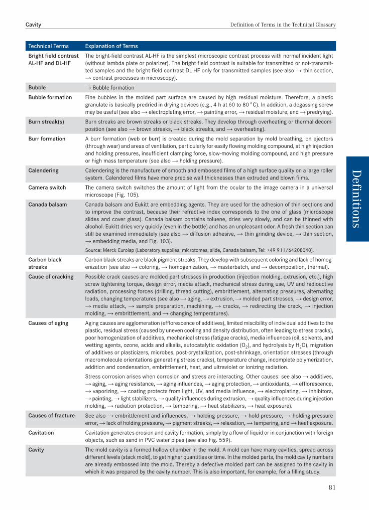
Technical Terms Explanation of Terms Bright field contrast AL-HF and DL-HF
The bright-field contrast AL-HF is the simplest microscopic contrast process with normal incident light (without lambda plate or polarizer). The bright field contrast is suitable for transmitted or not-transmit-ted samples and the bright-field contrast DL-HF only for transmitted samples (see also → thin section, → contrast processes in microscopy).
Bubble → Bubble formation Bubble formation Fine bubbles in the molded part surface are caused by high residual moisture. Therefore, a plastic
granulate is basically predried in drying devices (e.g., 4 h at 60 to 80 °C). In addition, a degassing screw may be useful (see also → electroplating error, → painting error, → residual moisture, and → predrying).
Burn streak(s) Burn streaks are brown streaks or black streaks. They develop through overheating or thermal decom-position (see also → brown streaks, → black streaks, and → overheating).
Burr formation A burr formation (web or burr) is created during the mold separation by mold breathing, on ejectors (through wear) and areas of ventilation, particularly for easily flowing molding compound, at high injection and holding pressures, insufficient clamping force, slow-moving molding compound, and high pressure or high mass temperature (see also → holding pressure).
Calendering Calendering is the manufacture of smooth and embossed films of a high surface quality on a large roller system. Calendered films have more precise wall thicknesses than extruded and blown films.
Camera switch The camera switch switches the amount of light from the ocular to the image camera in a universal microscope (Fig. 105).
Canada balsam Canada balsam and Eukitt are embedding agents. They are used for the adhesion of thin sections and to improve the contrast, because their refractive index corresponds to the one of glass (microscope slides and cover glass). Canada balsam contains toluene, dries very slowly, and can be thinned with alcohol. Eukitt dries very quickly (even in the bottle) and has an unpleasant odor. A fresh thin section can still be examined immediately (see also → diffusion adhesive, → thin grinding device, → thin section, → embedding media, and Fig. 103).Source: Merck Eurolap (Laboratory supplies, microtomes, slide, Canada balsam, Tel: +49 911/64208040).
Carbon black streaks
Carbon black streaks are black pigment streaks. They develop with subsequent coloring and lack of homog-enization (see also → coloring, → homogenization, → masterbatch, and → decomposition, thermal).
Cause of cracking Possible crack causes are molded part stresses in production (injection molding, extrusion, etc.), high screw tightening torque, design error, media attack, mechanical stress during use, UV and radioactive radiation, processing forces (drilling, thread cutting), embrittlement, alternating pressures, alternating loads, changing temperatures (see also → aging, → extrusion, → molded part stresses, → design error, → media attack, → sample preparation, machining, → cracks, → redirecting the crack, → injection molding, → embrittlement, and → changing temperatures).
Causes of aging Aging causes are agglomeration (efflorescence of additives), limited miscibility of individual additives to the plastic, residual stress (caused by uneven cooling and density distribution, often leading to stress cracks), poor homogenization of additives, mechanical stress (fatigue cracks), media influences (oil, solvents, and wetting agents, ozone, acids and alkalis, autocatalytic oxidation (O2), and hydrolysis by H2O), migration of additives or plasticizers, microbes, post-crystallization, post-shrinkage, orientation stresses (through macromolecule orientations generating stress cracks), temperature change, incomplete polymerization, addition and condensation, embrittlement, heat, and ultraviolet or ionizing radiation.Stress corrosion arises when corrosion and stress are interacting. Other causes: see also → additives, → aging, → aging resistance, → aging influences, → aging protection, → antioxidants, → efflorescence, → vaporizing, → coating protects from light, UV, and media influence, → electroplating, → inhibitors, → painting, → light stabilizers, → quality influences during extrusion, → quality influences during injection molding, → radiation protection, → tempering, → heat stabilizers, → heat exposure).
Causes of fracture See also → embrittlement and influences, → holding pressure, → hold pressure, → holding pressure error, → lack of holding pressure, → pigment streaks, → relaxation, → tempering, and → heat exposure.
Cavitation Cavitation generates erosion and cavity formation, simply by a flow of liquid or in conjunction with foreign objects, such as sand in PVC water pipes (see also Fig. 559).
Cavity The mold cavity is a formed hollow chamber in the mold. A mold can have many cavities, spread across different levels (stack mold), to get higher quantities or time. In the molded parts, the mold cavity numbers are already embossed into the mold. Thereby a defective molded part can be assigned to the cavity in which it was prepared by the cavity number. This is also important, for example, for a filling study.

82
Definition of Terms in the Technical Glossary Center vacuole
Def
initi
ons
Technical Terms Explanation of Terms Center vacuole A center vacuole usually occurs in thick-walled, symmetrical molded parts. The core remains plastic
longer and the plastic volume has more time to disappear in large wall thicknesses. The vacuoles become particularly large at a too-short holding time in the center of large-volume cross-sections (see also → shrinkage, → core, plastic, and → holding pressure time).
Certificate, testing → Test certificateChalk in PVC-U Chalk is a filling and processing aid (see also Fig. 337). The chalk content in plastics (e.g., PVC-U) is
calculated stoichiometrically from the sulfated ash content with ≅ 1.36 × chalk content% (SKZ formula; see also → filler materials and reinforcing materials testing).
Changing temperatures
Changing temperatures are rapidly varying temperatures in use or periodically created temperature changes in laboratory studies to determine the aging resistance of, for example, water pipes. Long-last-ing, rapidly changing temperatures shorten service life through structure degradation (see also → aging, → aging resistance, → matrix degradation, → service life, and → temperature influence).
Chemical baths In chemical baths, an increase in the → wettability occurs through an O2 involvement.Clamping block method (Measuring the film layer thicknesses)
With the clamping block method, layer thicknesses for multilayer films are examined much faster than after embedding in epoxy resin EP or by thin section. Between two PVC clamping blocks (see also Fig. 96), equally sized film cuts are inserted into both clamping sides so they remain parallel when tightening the brass screws. Both excess films are cut off (dragging diagonally) with a scalpel, flush with the PVC surface. Thereby, the developing cut grooves are located diagonally to the individual layers and do not simulate more layers than available. The scalpel cut is then measured microscopically. Caution: a thin section is suitable to identify the layers, but never shows the exact layer thickness due to an unavoidable transverse contraction like a scalpel or block section (sample residue between the clamping blocks or in the microtome).
Clamping force → Mold clamping force Cleaning agent influence
Release agent residues on the molded parts should be washed thoroughly with suitable cleaning agents, even against manufacturer’s instructions. Influences can be seen under → fading, → solvent evapora-tion, → delamination, → release agents, → color change, → electroplating error, → thread overload, → painting error, → surface discoloration, → preparation agents, → release agent, and → packaging and transportation.
Clouding When clouding on the molding surface occurs, the following processing parameters are too low: → injection rate (injection pressure), bulk temperature, or → mold temperature.
Coating Plastic surfaces are coated to beautify and to improve the feel, aging, sliding properties, and abrasion. The coating also protects against light, UV, and media influences (see also → haptics and → surface refining).
Cold embedding → EmbeddingCold flow Cold flow is the generic term for cold flow areas and cold flow errors due to a reduced molding compound
flow. Cold flow is, to our knowledge, one of the most common causes for damage. It is created during injection molding through cold processing and too-slow mold filling due to a low injection rate, molding compound temperature, narrow pinpoint gate, poor mold venting, defect jacket heating, high molding compound viscosity (filler and reinforcing materials, type of plastic), roughness of the flow path (polish sprue/gate, nozzle, and channels), core flowing, metal inserts (insert, without preheating), mold temperature, long flow paths, very thin flow cross-sections, and wall thickness as well as film hinges. See also → weld line with V-shaped collection of the surface and structures, which are similar to the weld line, → delamination (only through hot-cold streaks), → sink mark, → error, rheological, → molding compound, frozen, → inversion layers, → cold flow area, → cold flow front, → cold flow lines (record grooves), → cold plugs (cold particle), → flaking, → surface, tortured, → orange skin, → mold filling, poor (see also → extrusion, → error, rheological, → reversal of the flow front, → mass inversion, and → injection molding).
Cold flow area(s) → Cold flow Cold flow errors → Cold flow Cold flow line(s) A cold flow line is a warp in the molded part surface (see also → cold flow). Cold particles → Cold plug, → particle
145
Chapter 3
Quality and Damage Figures
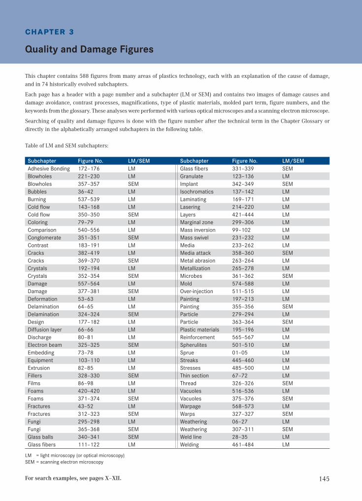
This chapter contains 588 figures from many areas of plastics technology, each with an explanation of the cause of damage, and in 74 historically evolved subchapters.
Each page has a header with a page number and a subchapter (LM or SEM) and contains two images of damage causes and damage avoidance, contrast processes, magnifications, type of plastic materials, molded part term, figure numbers, and the keywords from the glossary. These analyses were performed with various optical microscopes and a scanning electron microscope.
Searching of quality and damage figures is done with the figure number after the technical term in the Chapter Glossary or directly in the alphabetically arranged subchapters in the following table.
Table of LM and SEM subchapters:
Subchapter Figure No. LM/SEM Subchapter Figure No. LM/SEMAdhesive Bonding 172–176 LM Glass fibers 331–339 SEMBlowholes 221–230 LM Granulate 123–136 LMBlowholes 357–357 SEM Implant 342–349 SEMBubbles 36–42 LM Isochromatics 137–142 LMBurning 537–539 LM Laminating 169–171 LMCold flow 143–168 LM Lasering 214–220 LMCold flow 350–350 SEM Layers 421–444 LMColoring 79–79 LM Marginal zone 299–306 LMComparison 540–556 LM Mass inversion 99–102 LMConglomerate 351–351 SEM Mass swivel 231–232 LMContrast 183–191 LM Media 233–262 LMCracks 382–419 LM Media attack 358–360 SEMCracks 369–370 SEM Metal abrasion 263–264 LMCrystals 192–194 LM Metallization 265–278 LMCrystals 352–354 SEM Microbes 361–362 SEMDamage 557–564 LM Mold 574–588 LMDamage 377–381 SEM Over-injection 511–515 LMDeformation 53–63 LM Painting 197–213 LMDelamination 64–65 LM Painting 355–356 SEMDelamination 324–324 SEM Particle 279–294 LMDesign 177–182 LM Particle 363–364 SEMDiffusion layer 66–66 LM Plastic materials 195–196 LMDischarge 80–81 LM Reinforcement 565–567 LMElectron beam 325–325 SEM Spherulites 501–510 LMEmbedding 73–78 LM Sprue 01–05 LMEquipment 103–110 LM Streaks 445–460 LMExtrusion 82–85 LM Stresses 485–500 LMFillers 328–330 SEM Thin section 67–72 LMFilms 86–98 LM Thread 326–326 SEMFoams 420–420 LM Vacuoles 516–536 LMFoams 371–374 SEM Vacuoles 375–376 SEMFractures 43–52 LM Warpage 568–573 LMFractures 312–323 SEM Warps 327–327 SEMFungi 295–298 LM Weathering 06–27 LMFungi 365–368 SEM Weathering 307–311 SEMGlass balls 340–341 SEM Weld line 28–35 LMGlass fibers 111–122 LM Welding 461–484 LM
LM = light microscopy (or optical microscopy) SEM = scanning electron microscopy
For search examples, see pages X–XII.
146
Quality and Damage Figures
Figu
res
& Te
xt
LM Subchapter: Sprue
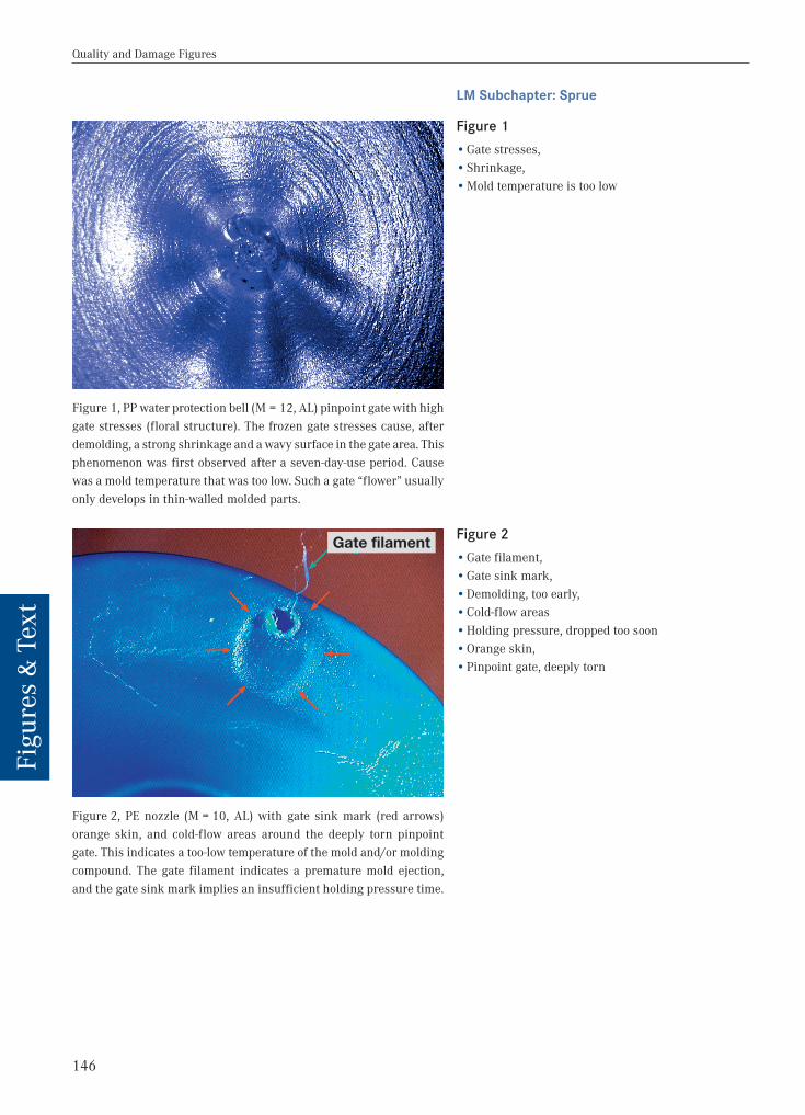
Figure 1, PP water protection bell (M = 12, AL) pinpoint gate with high gate stresses (floral structure). The frozen gate stresses cause, after demolding, a strong shrinkage and a wavy surface in the gate area. This phenomenon was first observed after a seven-day-use period. Cause was a mold temperature that was too low. Such a gate “flower” usually only develops in thin-walled molded parts.
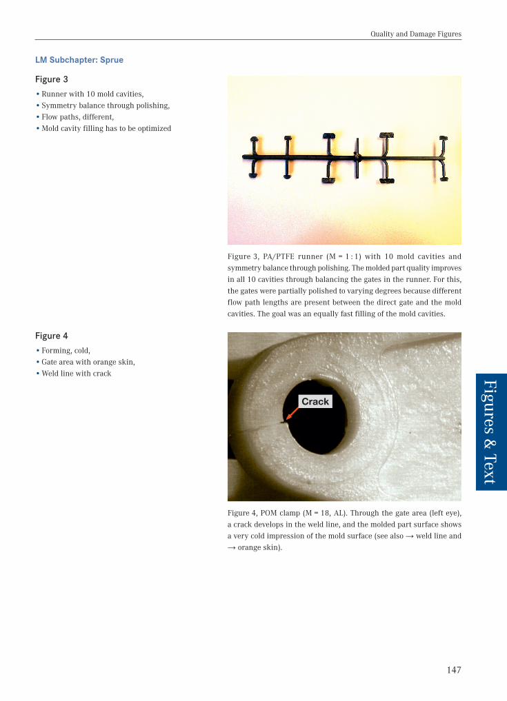
Figure 2, PE nozzle (M = 10, AL) with gate sink mark (red arrows) orange skin, and cold-flow areas around the deeply torn pinpoint gate. This indicates a too-low temperature of the mold and/or molding compound. The gate filament indicates a premature mold ejection, and the gate sink mark implies an insufficient holding pressure time.
Figure 1 •Gate stresses, •Shrinkage, •Mold temperature is too low
Figure 2 •Gate filament, •Gate sink mark, •Demolding, too early, •Cold-flow areas •Holding pressure, dropped too soon •Orange skin, •Pinpoint gate, deeply torn
Gate filament
147
Quality and Damage Figures
Figures & Text
LM Subchapter: Sprue
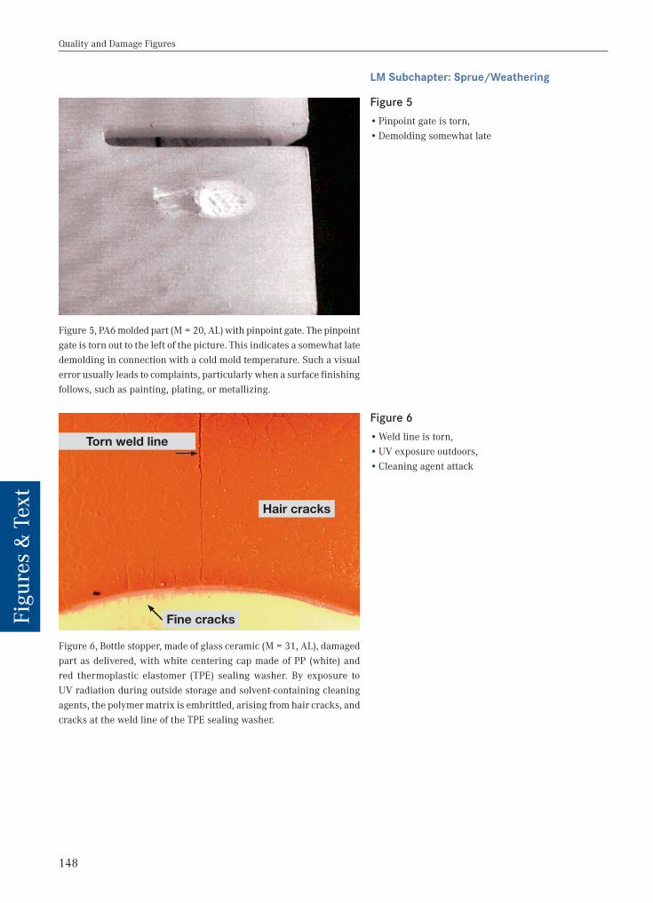
Figure 3, PA/PTFE runner (M = 1 : 1) with 10 mold cavities and symmetry balance through polishing. The molded part quality improves in all 10 cavities through balancing the gates in the runner. For this, the gates were partially polished to varying degrees because different flow path lengths are present between the direct gate and the mold cavities. The goal was an equally fast filling of the mold cavities.
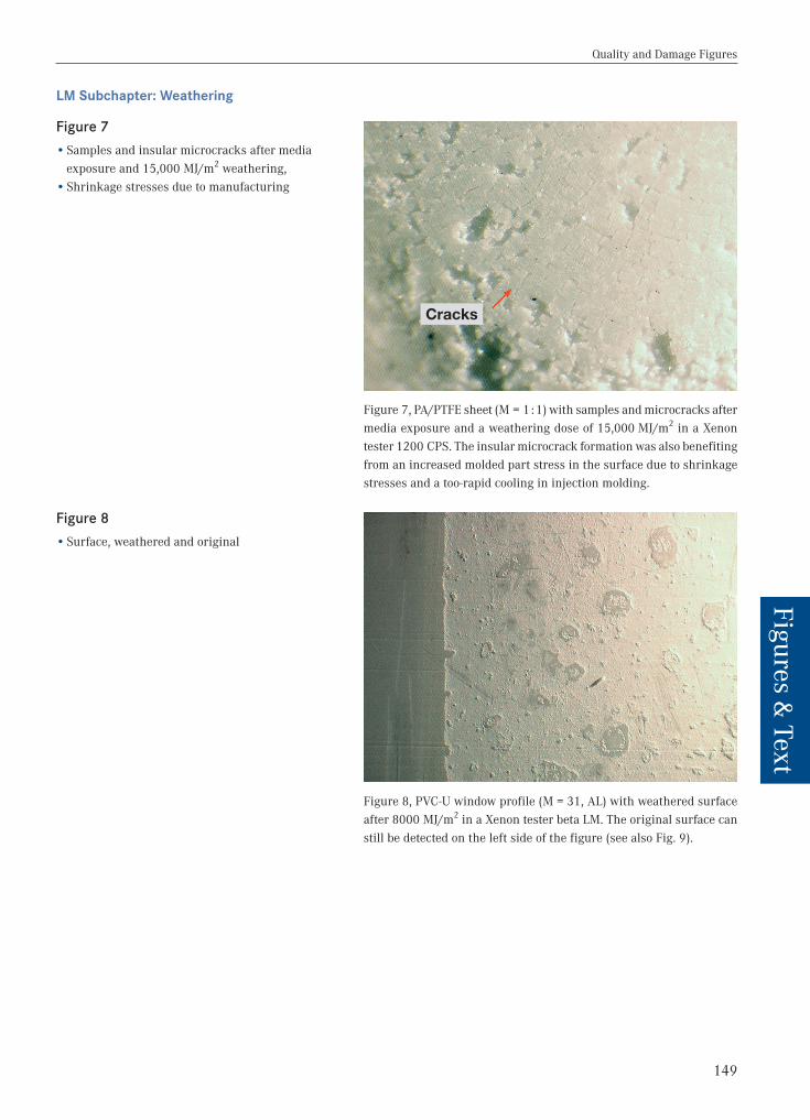
Figure 4, POM clamp (M = 18, AL). Through the gate area (left eye), a crack develops in the weld line, and the molded part surface shows a very cold impression of the mold surface (see also → weld line and → orange skin).
Figure 3 •Runner with 10 mold cavities, •Symmetry balance through polishing, •Flow paths, different, •Mold cavity filling has to be optimized
Figure 4 •Forming, cold, •Gate area with orange skin, •Weld line with crack
Crack
148
Quality and Damage Figures
Figu
res
& Te
xt
LM Subchapter: Sprue/Weathering
Figure 5, PA6 molded part (M = 20, AL) with pinpoint gate. The pinpoint gate is torn out to the left of the picture. This indicates a somewhat late demolding in connection with a cold mold temperature. Such a visual error usually leads to complaints, particularly when a surface finishing follows, such as painting, plating, or metallizing.
Figure 6, Bottle stopper, made of glass ceramic (M = 31, AL), damaged part as delivered, with white centering cap made of PP (white) and red thermoplastic elastomer (TPE) sealing washer. By exposure to UV radiation during outside storage and solvent-containing cleaning agents, the polymer matrix is embrittled, arising from hair cracks, and cracks at the weld line of the TPE sealing washer.
Figure 5 •Pinpoint gate is torn, •Demolding somewhat late
Figure 6 •Weld line is torn, •UV exposure outdoors, •Cleaning agent attack
Hair cracks
Fine cracks
Torn weld line
149
Quality and Damage Figures
Figures & Text
LM Subchapter: Weathering
Figure 7, PA/PTFE sheet (M = 1 : 1) with samples and microcracks after media exposure and a weathering dose of 15,000 MJ/m2 in a Xenon tester 1200 CPS. The insular microcrack formation was also benefiting from an increased molded part stress in the surface due to shrinkage stresses and a too-rapid cooling in injection molding.
Figure 8, PVC-U window profile (M = 31, AL) with weathered surface after 8000 MJ/m2 in a Xenon tester beta LM. The original surface can still be detected on the left side of the figure (see also Fig. 9).
Figure 7 •Samples and insular microcracks after media exposure and 15,000 MJ/m2 weathering, •Shrinkage stresses due to manufacturing
Figure 8 •Surface, weathered and original
Cracks
150
Quality and Damage Figures
Figu
res
& Te
xt
LM Subchapter: Weathering
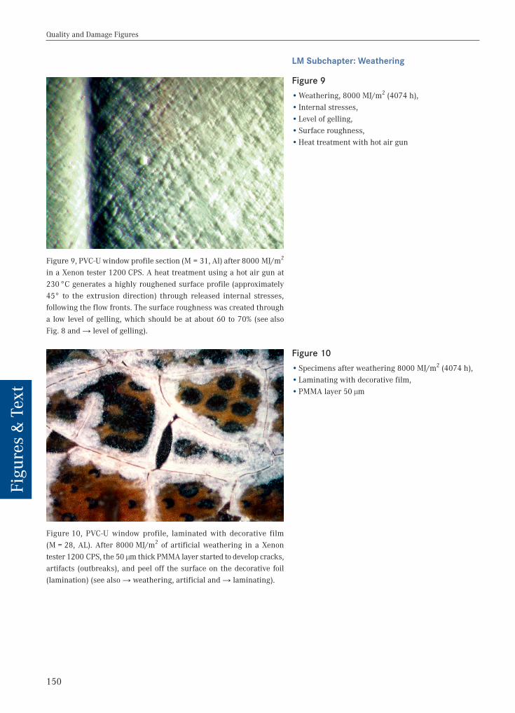
Figure 9, PVC-U window profile section (M = 31, Al) after 8000 MJ/m2 in a Xenon tester 1200 CPS. A heat treatment using a hot air gun at 230 °C generates a highly roughened surface profile (approximately 45° to the extrusion direction) through released internal stresses, following the flow fronts. The surface roughness was created through a low level of gelling, which should be at about 60 to 70% (see also Fig. 8 and → level of gelling).
Figure 10, PVC-U window profile, laminated with decorative film (M = 28, AL). After 8000 MJ/m2 of artificial weathering in a Xenon tester 1200 CPS, the 50 µm thick PMMA layer started to develop cracks, artifacts (outbreaks), and peel off the surface on the decorative foil (lamination) (see also → weathering, artificial and → laminating).
Figure 9 •Weathering, 8000 MJ/m2 (4074 h), • Internal stresses, •Level of gelling, •Surface roughness, •Heat treatment with hot air gun
Figure 10 •Specimens after weathering 8000 MJ/m2 (4074 h), •Laminating with decorative film, •PMMA layer 50 µm

151
Quality and Damage Figures
Figures & Text
LM Subchapter: Weathering
Figure 11, GF-UP sheet, transparent (M = 20, AL + DL). The cracks (hair cracks) in the sample surface developed after 5000 hours of weathering in a Xenon tester 1200 CPS. The crack depth is no deeper than about 35 µm. During recording, a low level of transmitted light has been combined with incident light.
Figure 12, PP lounge seat (M = 100, AL) with UV stabilization. A rough PP surface developed after four years of outdoor weathering in Würzburg, Germany. Thus the dirt deposits cannot be removed with the cleaning products that were recommended by the manufacturer, and the rough PP surface retained a gray appearance.
Figure 11 •Weathering 9818 MJ/m2 (5000 h), •Contrast process AL combined with DL, •Hair cracks after weathering
Figure 12 •Outdoor weathering, 4 years, •Surface with dirt deposits, •UV stabilization is poor
152
Quality and Damage Figures
Figu
res
& Te
xt
LM Subchapter: Weathering
Figure 13, EPDM gasket profile for PVC windows (M = 30, AL). After 8000 MJ/m2 artificial weathering in a Xenon tester beta LM the surface embrittled and caused formation of cracks and microcracks. An assess-ment of whether cracks are present or not is done by a combination bending of the sample ends in soft samples. Then the cracks opened and become gapingly visible.
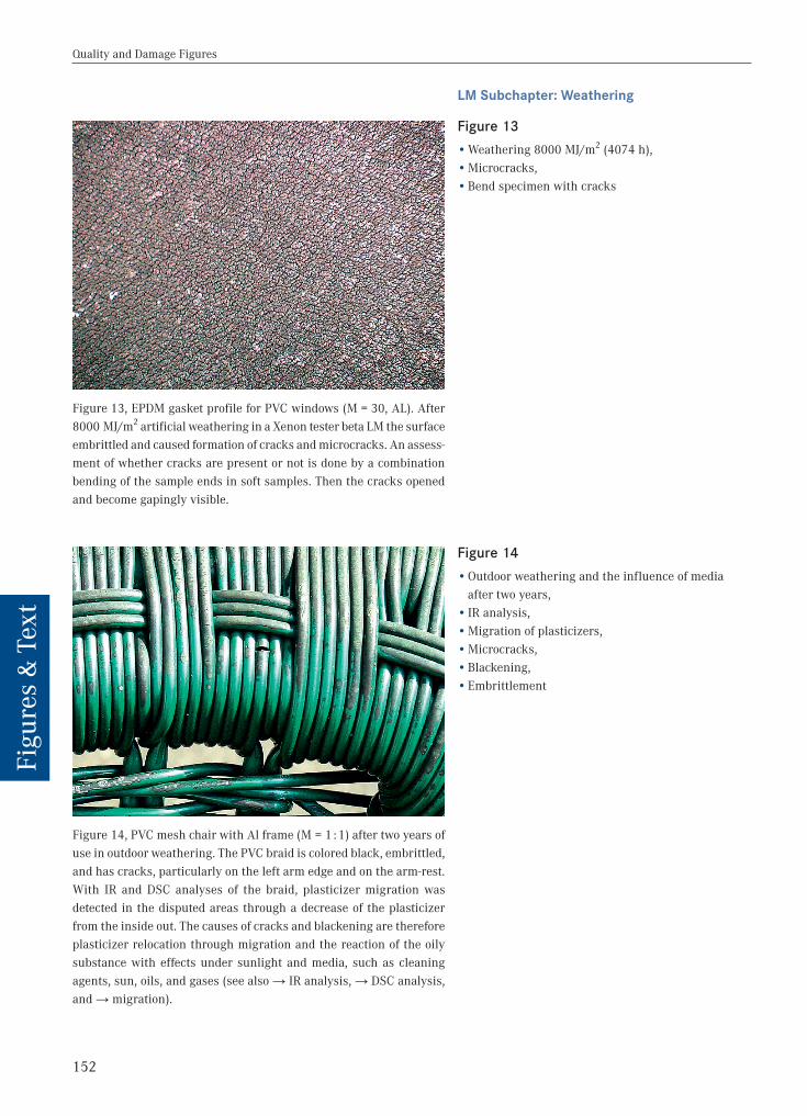
Figure 14, PVC mesh chair with Al frame (M = 1 : 1) after two years of use in outdoor weathering. The PVC braid is colored black, embrittled, and has cracks, particularly on the left arm edge and on the arm-rest. With IR and DSC analyses of the braid, plasticizer migration was detected in the disputed areas through a decrease of the plasticizer from the inside out. The causes of cracks and blackening are therefore plasticizer relocation through migration and the reaction of the oily substance with effects under sunlight and media, such as cleaning agents, sun, oils, and gases (see also → IR analysis, → DSC analysis, and → migration).
Figure 13 •Weathering 8000 MJ/m2 (4074 h), •Microcracks, •Bend specimen with cracks
Figure 14 •Outdoor weathering and the influence of media after two years, • IR analysis, •Migration of plasticizers, •Microcracks, •Blackening, •Embrittlement