hall d tagger infrastructure
DESCRIPTION
Hall D Tagger Infrastructure . Presented by Tim Whitlatch Hall D Engineer. What will be presented?. Overall layout Interfaces Infrastructure Electrical system requirements and layout Cooling systems requirements Assembly/Installation of the Tagger components Alignment ES&H Summary. - PowerPoint PPT PresentationTRANSCRIPT

Thomas Jefferson National Accelerator FacilityHall D Tagger Magnet Review July 10, 2009
Hall D Tagger Infrastructure
Presented by Tim Whitlatch Hall D Engineer
Page 1

Thomas Jefferson National Accelerator FacilityHall D Tagger Magnet Review July 10, 2009
What will be presented?Overall layoutInterfacesInfrastructure Electrical system requirements and layout Cooling systems requirements
Assembly/Installation of the Tagger componentsAlignmentES&HSummary
Page 2

Thomas Jefferson National Accelerator FacilityHall D Tagger Magnet Review July 10, 2009
Who is working on the mechanical design/fab?
Chuck Hutton – Lead Designer - design integration, Start counter, FDC, Pair spectrometer, schedulingWilliam Crahen - Mechanical Engineer- FDC, TOF, FCAL, conventional analysis and FEAGeorge Biallas – Senior Engineer (50%) – Solenoid cryogenics, magnetic fields and mechanical integration designVladislav Razmyslovich – Designer – CDC, gas systems, collimator and beamline, targetJames Lagner – Contract Designer – BCAL, Tagger magnet, vacuum chamber and HodoscopeFloyd Martin – Contract Designer– Solenoid magnetic field FEA, cryogenic test setup and mechanical designMark Stevens – Technician – FDC and solenoidJim Stewart – Scientist/Engineer – Tagger (gone to BNL)
Page 3

Thomas Jefferson National Accelerator FacilityHall D Tagger Magnet Review July 10, 2009
Photon beam and experimental area
Page 4
East arc
North linacTagger
area Hall D
ElectronBeam dump
Top View
75 m
Tagger Area ExperimentalHall D
Electron beam / dump
Coherent Bremsstrahlungphoton beam
Solenoid-Based detectorCollimator
PhotonBeam dump
Counting HouseRadiator
PairSpectrometer
Collimator Cave
Tagger
Thomas Jefferson National Accelerator FacilityHall D Tagger Magnet Review July 10, 2009
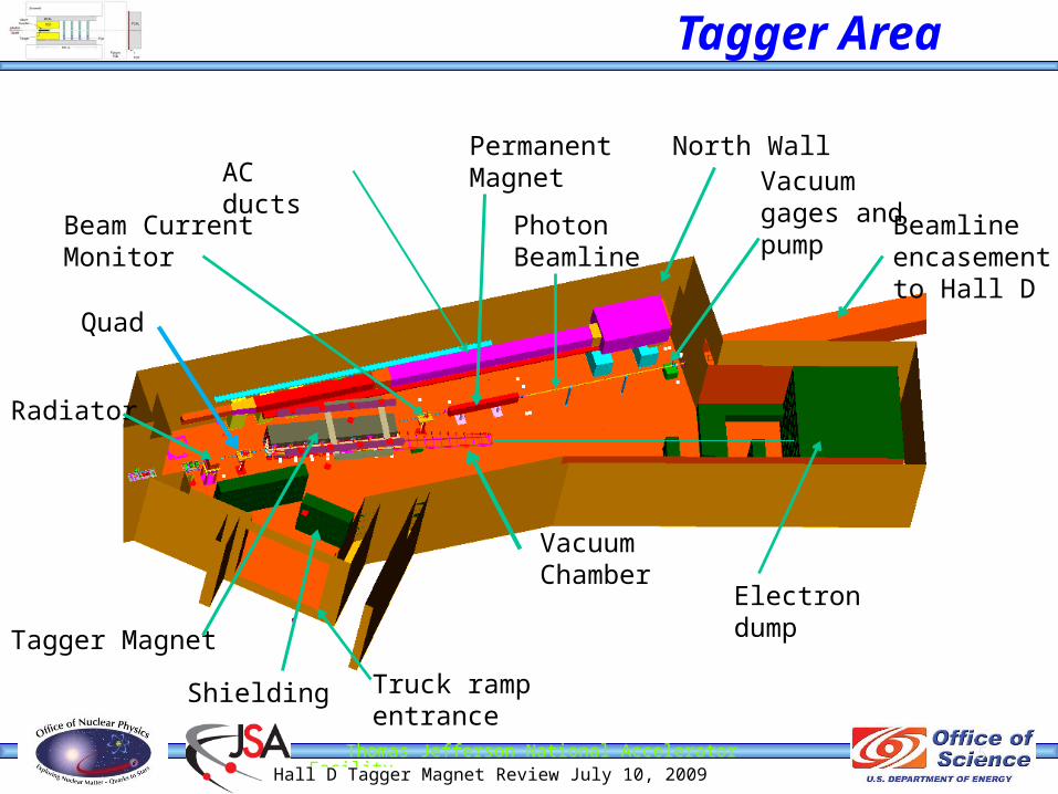
Tagger Area
5
North Wall
Shielding
Beamline encasement to Hall D
AC ducts
Radiator
Vacuum Chamber
Quad
Electron dump
Truck ramp entrance
Permanent Magnet
Tagger Magnet
Photon Beamline
Beam Current Monitor
Vacuum gages and pump

Thomas Jefferson National Accelerator FacilityHall D Tagger Magnet Review July 10, 2009
InterfacesCivil (utilities, structural loading)
Utilities (LCW, Chilled water, power…)Structural
AcceleratorVacuumMPSPSSElectron DumpCryogenicsSurvey and alignment
Page 6
Thomas Jefferson National Accelerator FacilityHall D Tagger Magnet Review July 10, 2009
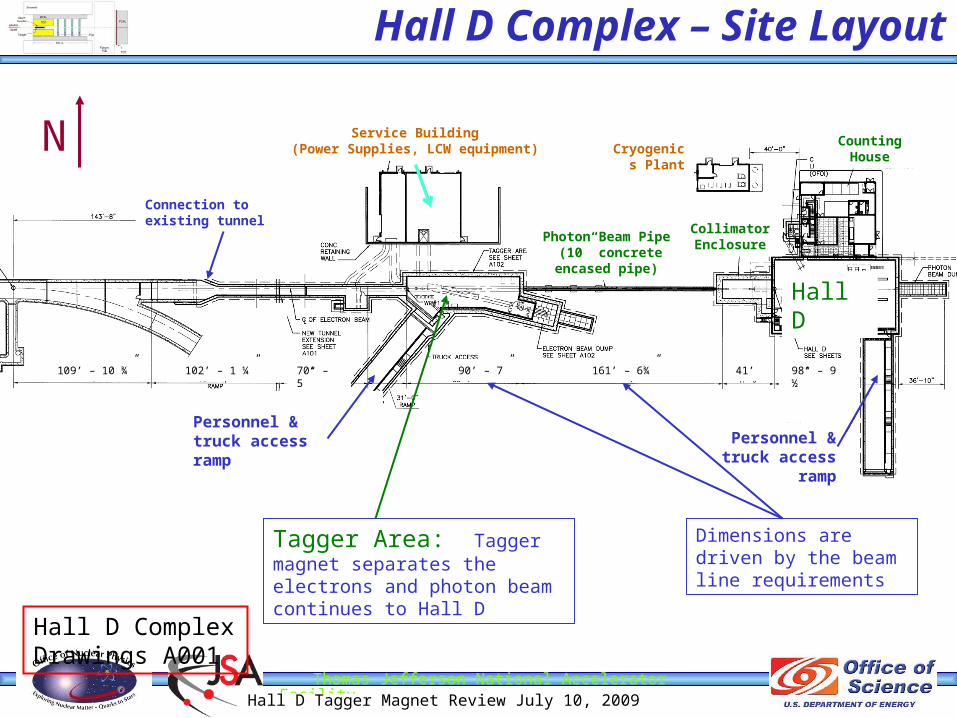
70’ – 5”
Hall D Complex – Site Layout
Hall D Complex Drawings A001
Tagger Area: Tagger magnet separates the electrons and photon beam continues to Hall D
N
Dimensions are driven by the beam line requirements
109’ – 10 ¾” 102’ – 1 ¼” 90’ – 7” 161’ – 6¾” 41’ 98’ – 9 ½”
Hall D
Personnel & truck access
ramp
Personnel & truck access ramp
Service Building(Power Supplies, LCW equipment)
Photon Beam Pipe (10” concrete encased
pipe)
Collimator Enclosure
Cryogenics Plant
Counting House
Connection to existing tunnel

Thomas Jefferson National Accelerator FacilityHall D Tagger Magnet Review July 10, 2009
Tagger Service Building/Tagger Hall
Page 8
Service Building
28 - 4” ducts for power and signal cables
•Magnet power supplies in service building•Vacuum gage controllers in service building•Tagger Hall temp. controlled (70°F, 55% hum max)
LCW from tunnel extension (85GPM available)
Electrical panels
Thomas Jefferson National Accelerator FacilityHall D Tagger Magnet Review July 10, 2009
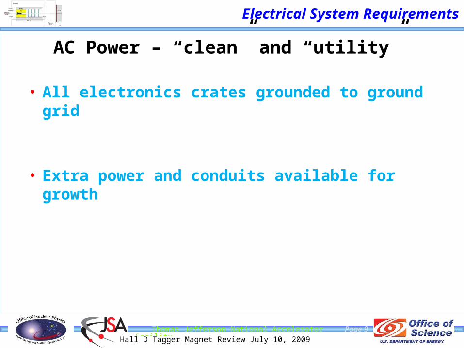
Electrical System Requirements
AC Power – “clean” and “utility”
• All electronics crates grounded to ground grid
• Extra power and conduits available for growth
Page 9

Thomas Jefferson National Accelerator FacilityHall D Tagger Magnet Review July 10, 2009
• Magnet built in pieces < 25 tons
• Support plates embedded in ceiling
• Strong back for handling vacuum vessel needed
10
Installation Concept
Magnet
Support plates
I-beam track
25 Ton carriage
Thomas Jefferson National Accelerator FacilityHall D Tagger Magnet Review July 10, 2009
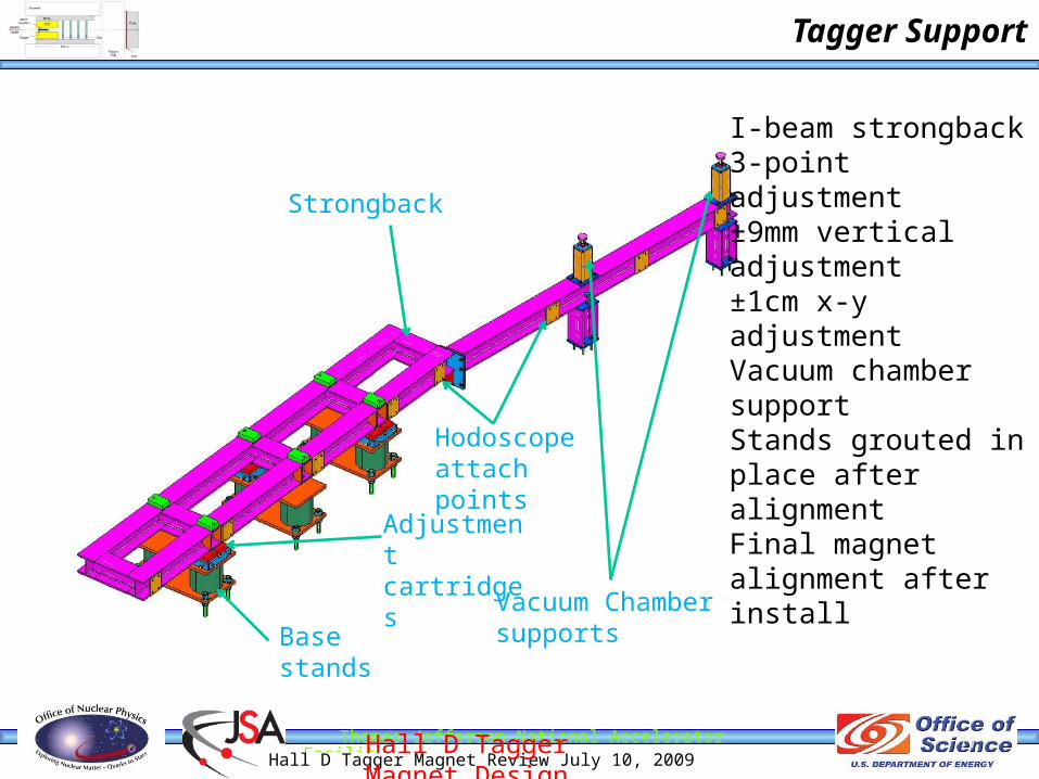
Tagger Support
Hall D Tagger Magnet Design Review July 10, 2009
11
I-beam strongback3-point adjustment±9mm vertical adjustment±1cm x-y adjustmentVacuum chamber supportStands grouted in place after alignmentFinal magnet alignment after install
Strongback
Vacuum Chamber supportsBase stands
Adjustment cartridges
Hodoscope attach points
Thomas Jefferson National Accelerator FacilityHall D Tagger Magnet Review July 10, 2009
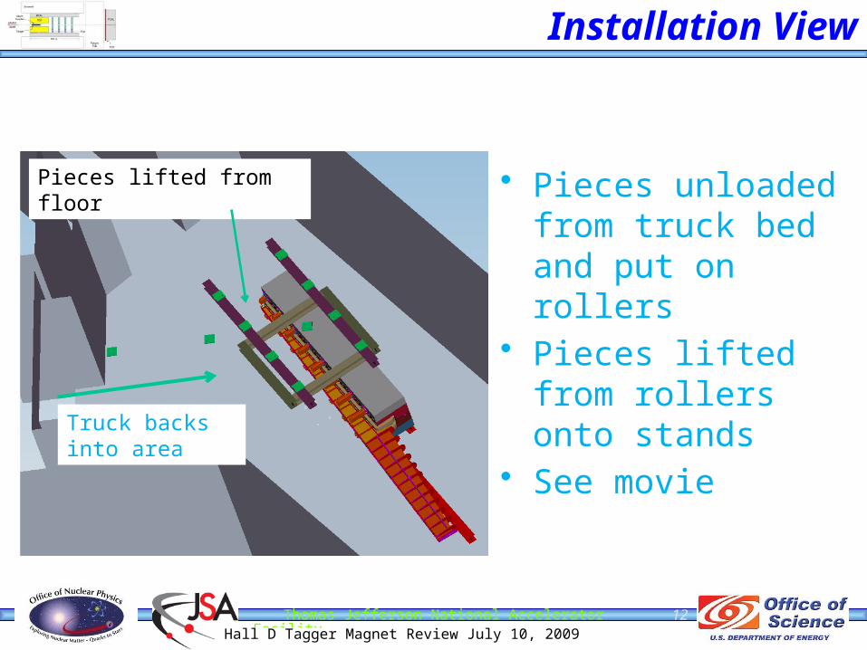
• Pieces unloaded from truck bed and put on rollers
• Pieces lifted from rollers onto stands
• See movie
12
Installation View
Pieces lifted from floor
Truck backs into area

Thomas Jefferson National Accelerator FacilityHall D Tagger Magnet Review July 10, 2009
13
• Network of fiducial monuments around the tagger hall tie into the main accelerator within 0.75 mm.
• Visible fiducials on tagger steel for alignment relative to electron beam• Measure alignment with magnet off and magnet on
ALIGNMENT CONSIDERATIONS

Thomas Jefferson National Accelerator FacilityHall D Tagger Magnet Review July 10, 2009
Environmental Safety & HealthPrior to installation safety review…
Task Hazard AnalysisHDListTOSP/SOPSpecific Procedures writtenUse Design Authority for pressure systemsDesign Review
Page 14
Thomas Jefferson National Accelerator FacilityHall D Tagger Magnet Review July 10, 2009
Environmental Safety and Health
Personnel Safety System (PSS)Magnetic door locksVestibule camerasRun/stop boxesODH alarmsRadiation AlarmsMagnet power alerts/barricadesExhaust fansFire suppression system
Page 15
Thomas Jefferson National Accelerator FacilityHall D Tagger Magnet Review July 10, 2009
Environmental Safety and Health
Machine Protection System (MPS)Vacuum monitoringMagnet temperature monitoring
Equipment ProtectionTemperature monitoring (Electronics and magnets)Radiation monitoringCurrent/voltage monitoringKlixons to shut off magnets
Page 16

Thomas Jefferson National Accelerator FacilityHall D Tagger Magnet Review July 10, 2009
Summary
Interfaces have been addressed Infrastructure consistent with magnet
requirements ES&H plans in place – to be developed further as
the tasks grow near. Installation and alignment addressed.
Page 17
Thomas Jefferson National Accelerator FacilityHall D Tagger Magnet Review July 10, 2009
18
Back Up Slides

Thomas Jefferson National Accelerator FacilityHall D Tagger Magnet Review July 10, 2009
Tagger Area
Page 19
North Wall
Shielding
Beamline encasement to Hall D
AC ducts
Radiator
Vacuum Chamber
Quad
Electron dump
Truck ramp entrance
Permanent Magnet (MPS)
Tagger Magnet
Photon Beamline
Vacuum gages, Ion gages and pump (MPS)

Thomas Jefferson National Accelerator FacilityHall D Tagger Magnet Review July 10, 2009
20
Tagger Achievable Alignment
• Use optical means to determine relation between pole edges and fiducials on each slab within 50 microns
• Laser tracking fiducial targets on tagger magnet to position relative to monuments within 40 microns
• Absolute position relative to accelerator within 0.75mm
Targets visible after install on upstream end

Thomas Jefferson National Accelerator FacilityHall D Tagger Magnet Review July 10, 2009
Vacuum Chamber
Stiffening ribs 1 inch plate
Skin, 0.25 inch plate
O-ring groove along entire edge, top and bottom
Cut out for photon beam tube
Page 21

Thomas Jefferson National Accelerator FacilityHall D Tagger Magnet Review July 10, 2009
22
• Adjustment cartridges use wedge type for vertical
• Sliders for X-Z• +/- 2cm horizontal plane
adjustment• +/- 9mm vertical
adjustment
Tagger End View
Adjustment cartridges

Thomas Jefferson National Accelerator FacilityHall D Tagger Magnet Review July 10, 2009
Environmental Safety & Health
Task Hazard Analysis for Hall D Forward Drift Chamber (FDC) per JLAB ES&H manual chapter 3210Task ID # System
Description Resp Hazard Cause Risk Code (pre) Mitigation Administrative Mitigation Engineering Applicable ES&H Manual Chapter Risk Code
(post)
Gas System ENG/TECH
N/A Pressure related injury Over pressure of system 2
written procedure for maintenance/repair
System will release pressure at more than a couple of PSI 6150, 6151 0
ODH Gas leak 2 use proper labeling and handling procedures Design system to limit gas flow 6500 0
Burns Flammable gases 3 Use non-flammable gas mixtures 6152 0N/A Assembly
ENG/TECHHand Injury Sharp edges 2 Wear gloves when necessary,
use tools properlyrequire radii/chamfers on all edges 6120, 6620 1
Back/Body Injury Back Strain 3 Use proper lifting techniques Where possible use mechanical equipment for heavy lifting
6140 1
Slip/Trip/Fall 2 Clean work areas, use proper tooling, work planning
Design proper tooling 6131 Trip and Fall Hazards 1
Chemical exposure Exposure to glues and cleaning agents
2 Use Proper PPE Spec only non-toxic chemicals 6610 0
N/A ElectronicsENG/TECH
Electrical shock exposed live wires/components
2 Put Procedure in place to ensure power off when handling
Design system so there are no exposed live components
6210, 6220, 6230 1
burns over heat, sparks, fire 2 use proper fab techniques Cooling where required 6240 1N/A Cooling system
ENG/TECHpressure related injury
Overpressure of system 2 written procedure for maintenance/repair
Provide pressure relief in design 6151 0
N/A InstallationENG/TECH
Hand Injury Pinch point, 2 Work at a pace conducive to safety. Wear gloves, use written procedure
Design proper tooling 6120, 6620 1
Back/Body Injury Back Strain 3 Use proper lifting techniques Where possible use mechanical equipment for heavy lifting
6140 1
Slip/Trip/Fall 2 Clean work areas, use proper tooling, work planning
Design proper tooling 6131 Trip and Fall Hazards 1
Elevated work 3 Proper positioning, PPE Provide proper railings etc… 6131 1 Foot injury Dropped equipment. 2 Work at a pace conducive to
safety. Steel toes 0
Head Injury Dropped/moving equipment.
3 Proper PPE (Hard hat) and use qualified crane operators
Design proper tooling and pick points
6140 1

Thomas Jefferson National Accelerator FacilityHall D Tagger Magnet Review July 10, 2009
Design Load DataComponent Weight Load capability
Solenoid 307 tons --------------
BCAL 30 tons --------------
CDC 600 lbs --------------
FDC 200 lbs --------------
Target/Start counter/structure
800 lbs --------------
FCAL 15 tons --------------
Pair Spectrometer 65 tons --------------
Upstream Platform 9 tons 35 tons
Cryo platform 1 ton >2 tons
Downstream platform 4 tons 20 tons
Overhead crane -------------- 20 tons
Tagger Magnet 80 tons ------------
Shielding 5 tons (max per piece) ---------------
Page 24

Thomas Jefferson National Accelerator FacilityHall D Tagger Magnet Review July 10, 2009
Hall D AC Power Requirements
Hall D Program Power RequirementsHall D Program Power Requirements
(continued)
Load Description LoadClean Pwr Util Pwr Load Description Load Clean Pwr Util Pwr
Experimental Equipment TOF Readout 6 kVA 6 kVA
CDC 12kVA 12kVA TOF HV 3 kVA 3 kVA
FDC 24 kVA 24 kVA Collimator I&C 5 kVA 5 kVA
CDC HV and Bias Supplies 3 kVA 3 kVA Trigger System 12 kVA 12 kVA
FDC HV and Bias Supplies 6 kVA 6 kVA Network Gear 3 kVA 3 kVA
Barrel Calorimeter 48 kVA 48 kVA Target Instrumentation 2 kVA 2 kVA
Bcal HV and Bias Supplies 6 kVA 6 kVA Control System Instrumentation 16 kVA 16 kVA
Start Counter 4 kVA 4 kVA Solenoid PS 75 kVA 25 kVA 50 kVA
Start Counter HV & Bias 2 kVA 2 kVA Sweep Magnets PS 10 kVA 10 kVA
FCAL 24 kVA 24 kVA Platform Power (Chill blowers, Vacuum pumps, lights etc) 30 kVA
30 kVA
FCAL HV and Bias supplies 3 kVA 3kVA Envelope and Other (Crane, lights outlets., Air handlers.) 200 kVA 200 kVA
Pair Spectrometer PS 190 kVA 10 kVA 180 kVA Subtotal 225 kVA 460 kVA
Pair Spectrometer HV 1 kVA 1 kVA Total Required 685 kVA
Total Available > 1000 kVA
Room to grow!
Thomas Jefferson National Accelerator FacilityHall D Tagger Magnet Review July 10, 2009
26
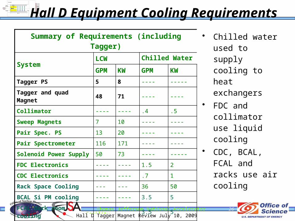
Hall D Equipment Cooling Requirements
Summary of Requirements (including Tagger)
SystemLCW Chilled Water GPM KW GPM KW
Tagger PS 5 8 ---- -----
Tagger and quad Magnet 48 71 ---- ----
Collimator ---- ---- .4 .5
Sweep Magnets 7 10 ---- ----
Pair Spec. PS 13 20 ---- ----
Pair Spectrometer 116 171 ---- ----
Solenoid Power Supply 50 73 ---- -----
FDC Electronics ---- ---- 1.5 2
CDC Electronics ---- ---- .7 1
Rack Space Cooling --- --- 36 50
BCAL Si PM cooling ---- ---- 3.5 5
FCAL dark room cooling 3.5 5
Total Required 239 353 46 64
• Chilled water used to supply cooling to heat exchangers
• FDC and collimator use liquid cooling
• CDC, BCAL, FCAL and racks use air cooling

Thomas Jefferson National Accelerator FacilityHall D Tagger Magnet Review July 10, 2009
27
Hall D Complex - Cooling Requirements
Summary of Requirements
Area/SystemLCW Chilled Water
GPM KW GPM KWPhysics Equipment (PE) 239 353 45 65
Tagger (excluding PE) 39 57 33 49
Hall D & Collimator (exc. PE) ---- ---- 159 223
Service Bldg (Excluding PE) 24 35 48 70
Counting house ---- ---- 123 174
Tunnel extension 50 74 11 16
Total Required 352 519 419 597
Total Available 400 585 600 880
With room to grow!

Thomas Jefferson National Accelerator FacilityHall D Tagger Magnet Review July 10, 2009
Page 28
Allowables in “Space Program”