guide to sollysta wiring accessories - hager guide to sollysta... · this guide expands upon some...
TRANSCRIPT

Guide tosollysta Wiring Accessories

This guide expands upon some of the requirements found in the 17th Edition of the IEE Wiring Regulations and Building Regulations and how they affect wiring accessories.
You should be aware that this guide does not ensure compliance with BS7671 or the building regulations. You should always consult the relevant regulations to ensure compliance.
Introduction

While the author believes that the information and guidance given in this document is correct, all parties must rely upon their own skill and
judgment when making use of it. The author does not assume any liability to anyone for loss or damage caused by any error or omission in the
work, whether such error or omission is the result of negligence or any other cause. Any and all such liability is disclaimed.
ContentsSelection and erection Page 4
Lighting Page 6
Power Page 10
Connection & switching points in a kitchen Page 14
TV systems Page 16
Building regulations Page 17

Guide to | sollysta Wiring Accessories4
Selection and erectionAll equipment must be correctly selected and erected. BS 7671 states that the following, along with manufacturer’s instructions should be considered:
• Compliance with standards• Operational conditions• External influences• Accessibility
BS 7671 recognises equipment complying with anappropriate British Standard or Harmonised Standard without further qualification. This approach means that the person responsible for specifying the equipment must identify the “appropriate” standard. The relevant British Standards for wiring accessories are identified to the right:
The wiring accessory is usually the final connection of the fixed wiring. The installer needs to follow manufacturers’ instructions in order to install the correct back box at the first fix stage. This will avoid any frustrations later with there being insufficient room within the box for the cables.
Product Group Standard10AX Wall Switch BS EN 60669-1Dimmer Switches BS EN 60669-2-1 (including
BS EN 550155A Unswitched socket BS 54613A Switched & Unswitched Socket BS 1363-213A Fused Spur BS 1363-420A Functional Switches BS EN 60669-120A Isolation Switches BS EN 60669-2-420A Cable Outlets BS 573345A Functional Switches BS EN 60669-145A Isolation Switches BS EN 60669-2-445A Cable Outlets BS 573345A Cooker Control Units BS 417710AX Ceiling Switches BS EN 60669-1Fan Isolator Switches BS EN 60669-2-450A Ceiling Switches BS EN 60669-2-4Shaver Socket BS EN 61558-2-5TV Outlets BS 3041Satellite Outlets BS EN 50083-2Telephone Sockets BS EN 6313-2Surface Boxes BS EN 60670-1

Guide to | sollysta Wiring Accessories 5
The accessory may also provide a termination between solid and flexible conductors such as in a flex outlet plate used, among other applications, for a heated towel rail in a bathroom. The installer needs to consider the type of cables being joined or terminated here as prescribed in 526.2. It would be appropriate to terminate wherever possible solid and stranded conductors into separate terminals in order to fully comply.

Guide to | sollysta Wiring Accessories6
LightingLight switches & load typeElectrical equipment selected shall have suitable characteristics appropriate to the values and conditions on which the design of the electrical installation is based.
These conditions include voltage, current, frequency, power, environmental conditions and prevention of harmful effects. The designer needs to consider the types of loads which are to be controlled taking into consideration any instructions from the manufacturer. Fluorescent loads are commonplace, particularly in commercial installations.
BS EN 60669-1 is the standard for switches for household and similar fixed-electrical installations. The manufacturer is required to declare and mark the switch with the rated current in amperes (A) or rated fluorescent load in amperes (AX). Hence a switched marked AX will not require derating when used with fluorescent loads.
DimmingRarely in the modern home is lighting controlled purely by switching on and off, but dimming is required. Also a very popular light fitting is the downlighter which comes in various different forms, (i.e. mains or ELV).
The dimmer switch is an electronic device that controls the energy delivered to the light fitting and hence controls its’ light output. Installers need to select the correct dimmer switch especially if ELV lights are being used with dimmable transformers. The selection of the most up to date devices with leading edge technology means that such a dimmer can operate both ELV or mains voltage lights and not cause any loss of performance.
Often dimmers, when used with 2-way switching will only dim from one position, with the secondary position just turning on & off. Today dimmer switches are available offering master/slave capability so dimming and switching is available from more than one position.
“Ensure correct dimmers are used for the type of load”.

Guide to | sollysta Wiring Accessories 7

Guide to | sollysta Wiring Accessories8
Domestic lighting circuits have for many years been connected using the 3 plate method where the loop terminal is at the ceiling rose.
It is increasing likely however that there will be some kind of decorative light fitting or even downlighters installed in the modern home. The loop connections in this case may be in an inaccessible position within a junction box.
This method is non-compliant with BS7671 as all electrical connections (except for those designed to be inaccessible, 526.3 refers) should be accessible for inspection, testing or maintenance.
For this reason it is becoming increasingly popular to carry out this loop connection at the switch itself. This has the advantage in that the connections are now obviously accessible and the connections can be made at a more convenient working height.
You will require more connections than that which are on the conventional light switch. One solution is to connect the neutral to a connector block inside the wall box. Another is to use a product where there is a dedicated terminal in order to make the required connections.
cpc omitted for clarity
Lighting connections
“Consider using switches having additional neutral loop terminal”.
L N L N L N
LOOP LOOP LOOP

Guide to | sollysta Wiring Accessories 9
One of the fundamental requirements of BS 7671 is to provide Basic protection against electric shock. This is usually provided by preventing a current from passing through the body. ie preventing someone from touching a live part.
Section 416 gives the specific requirements of providing basic protection and it is specified that live parts shall be inside enclosures or behind barriers providing the degree of protection to at least IPXXB or IP2X. If there is a horizontal top surface of an enclosure which is readily accessible, this degree of protection shall be at least IPXXD or IP4X.
The requirement of this regulation does not apply to certain items of equipment such as BC lampholders to BS EN 61184 as access is required in order to insert the lamp. There is therefore an electric shock risk if there was no lamp within the holder.
Today, safety lampholders are available which incorporate a mechanism so that the exposed pins are not live if there is no lamp inserted, thus providing a safer installation - such bayonet lampholders with enhanced safety comply with BS 7895.
BC lampholders“Safety lampholders provide extra safety when using BC lampholders”.

Guide to | sollysta Wiring Accessories10
PowerRequirements for Cooker connectionsThe cooker switch or cooker control unit is typically installed to provide the following 2 functions:
1. To provide a means of isolation so as to facilitate replacement or repair of the cooker unit without having to isolate at the consumer unit. Table 53.2 of BS 7671 provides guidance as to the standard for such devices. BS EN 60669-2-4 is a suitable standard for isolation switches for household and similar applications. Also identified in Table 53.2 is BS 4177, for cooker control units to provide the function of isolation.
2. Switching off for mechanical maintenance to avoid the risk of burns or mechanical injury when cleaning or maintaining the cooker.
A current rating of up to 45A is sufficient for most household cooking appliances.
The position of such a unit should be should be such that it is accessible and convenient for use. It should not be positioned directly behind the cooking surface in order to avoid someone needing to reach over the appliance in order to access it. The horizontal distance should be such that the switch is under the control of anyone needing to access it. A maximum distance of 2m is likely to meet this requirement.
The final connection to the cooker unit will usually be by means of a cooker connection unit on the wall behind the cooker itself. This enables easier connection and disconnection for maintenance or replacement.
Where two stationary cooking appliances are in the same room, one switch may be used to control both appliances and is recommended that neither appliance is more than two metres from that switch.
“It is recommended that the cooker control switch is within 2m of the appliance”.

Guide to | sollysta Wiring Accessories 11
BS 1363 socket-outletsAs previously described basic protection is to provide protection against electric shock under fault free conditions.
Socket outlets having apertures for plug pins will fulfil the requirement as the apertures are smaller than that specified by IPXXB or IP2X. In addition to this they will have a shutter mechanism that prevents access to live parts unless the earth pin is also present and has been inserted first.
This however can be either intentionally or inadvertently defeated by inserting something into the earth pin aperture first.
For this reason, a designer could specify a manufacture that uses additional measures so that the shutter mechanism cannot be inadvertently defeated. They usually require all three pins to be present and the earth pin to be inserted first order to gain access
High protective conductor currentsThis situation is covered in regulation 543.7. Protective conductor currents can be caused by electronic equipment such as computers printers etc. They can also be caused by certain luminaires or heating elements however.
This can be a problem for an individual item of equipment but usually needs to be considered where several items of equipment, each producing a small amount of protective conductor current, are connected on the same circuit. If the accumulated current exceeds 10mA then the requirements of 543.7.1.3 need to be considered.
Of the five options within this regulation, the most common solution is (iii) where two protective conductors are used.543.7.1.4 specifies that where this solution is used the two ends of the protective conductor must be independently terminated at all connection points throughout the circuit.

Guide to | sollysta Wiring Accessories12
In the diagram above it can be seen that the protective conductor is terminated independently at all points throughout the circuit including the distribution board. Radial circuits if used can be wired with the protective conductor similarly as a ring.
A label is required at the distribution board so that anyone modifying this circuit has the required information.
“Sockets having two earth terminals may be necessary”.
N L

Guide to | sollysta Wiring Accessories 13
Fused connection unitsA 13A fused connection unit could be used for many applications. One of which could be to supply an electric towel rail in a bathroom. This equipment may need to be isolated for inspection, testing or maintenance.
Such a unit if used for isolation needs to be designed or installed so as to prevent unintentional or inadvertent closure as described in 537.2.2.3. Therefore if the fused connection is not under the immediate supervision of the person working on the towel rail then the whole circuit may have to be isolated at the distribution board.
Alternatively the fused connection unit may have a feature whereby it can be locked with the fuse carrier out and thereby satisfying the regulations as far as securing the isolation is concerned. BS 7671 table 53.2 identifies BS 1363-4 as a device suitable for isolation
“A device used for isolation needs to prevent inadvertent reclosure”.

Guide to | sollysta Wiring Accessories14
It has become increasingly popular in a kitchen that instead of having several fused connection units around to feed the appliances, one central point is utilised instead. This usually involves a grid switch plate with modular switches and fuses. Overload protection needs to be considered by the designer.
A ring final circuit is the usual method of feeding the sockets and appliances which assumes the power consumed will be distributed from several points on the circuit. Should a central control point be used however, the power for all those appliances are effectively distributed from that one point. Overload protection may not be provided in accordance with regulation 433.1.1. The designer will need to assess the current demand at this point and ensure this would not exceed the current rating for long periods of either part of the ring.
As an alternative a radial system may be considered for the appliances having central control. The cable feeding this control point would need to be suitably rated however for the load and hence may result in a large csa.
Connection and switching points in a kitchen
“Consider overload protection where kitchen central control is used”.

Guide to | sollysta Wiring Accessories 15
Fan Isolators3 pole fan isolation switches are commonly installed in household applications so that the fan in the bathroom can be completely disconnected from the supply. This may be to provide the functions of Isolation or switching off for mechanical maintenance (functions previously described under cooker connections).
Fans in bathrooms are commonly activated by turning on the light and incorporate a run on timer. For this reason a 3 pole device is required to disconnect both the permanent and switched – line conductors.
These devices are required to be secured so as to prevent unintentional reclosure or are required to be placed so as under the control of the person working on or replacing the fan. A normal wall mounted fan isolation switch will be required to be located outside of zone 2 as described in BS 7671 section 701. Should this not be practical a ceiling mounted version might be considered that is operated via a pull cord. In either case a suitable device would be one complying with BS EN 60669-2-4.
Shaver socket outletsShaver sockets are common place in domestic installations, usually in the bathroom. The required standard for this device is BS EN 61558-2-5. This unit provides electrical separation for one item of equipment (i.e. the shaver) as described in BS 7671. This device is permitted in zone 2 as described in regulation 701.512.3.
“Shaver sockets are permitted in zone 2 or outside of zones”.
Ceiling
2.25m
0.6m
Zone 1
Zone 0
Zone 2
Guide to | sollysta Wiring Accessories16
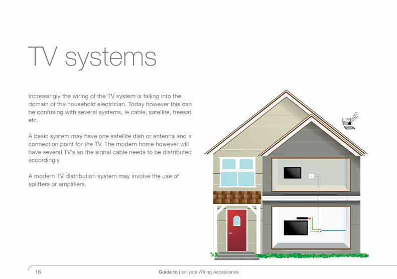
Increasingly the wiring of the TV system is falling into the domain of the household electrician. Today however this can be confusing with several systems, ie cable, satellite, freesat etc.
A basic system may have one satellite dish or antenna and a connection point for the TV. The modern home however will have several TV’s so the signal cable needs to be distributed accordingly
A modern TV distribution system may involve the use of splitters or amplifiers.
TV systems

Guide to | sollysta Wiring Accessories 17
Building regulations part M is for Access to and use of buildings. It relates, among other things, to how easy the controls for the various services and systems for the building can be operated by those who need to do so.
Key factors that affect the use of switches, socket-outlets and controls are ease of operation, visibility, height and freedom from obstruction. It is considered advantageous for
those with limited dexterity for switches on multiple socket outlets to be separated and for light switches to have larger rockers. It is also considered reasonable provision to provide these switches, sockets and controls at a height between 450mm and 1200mm from finished floor level
As far as dwellings are concerned, this applies to a new building only not to extensions or rewires.
Building regulations“Switches & sockets should be mounted between 450 & 1200mm”.
450mm
1200mm
DoorbellsEntry phones Switches
Sockets TV Sockets Telephone Jack Points
Maximum
Minimum

Guide to | sollysta Wiring Accessories18

Guide to | sollysta Wiring Accessories 19

Hager Ltd. Internal Sales Hotline: 01952 675612Hortonwood 50 Internal Sales Faxline: 01952 675645TelfordShropshire Technical Helpline: 01952 675689TF1 7FT Technical Faxline: 01952 675557 www.hager.co.uk [email protected] [email protected]
Hager Ltd. Northern Ireland Tel: 028 9077 3310Unit M2 Northern Ireland Fax: 028 9073 3572Furry Park Industrial EstateSwords Road Republic of Ireland Tel: 1890 551 502Santry Republic of Ireland Fax: 1890 551 503Dublin 9 www.hager.ieIreland
GU
IDE
WA
611-
RE
V2