industrial control wiring guide -...
TRANSCRIPT

Industrial Control
Wiring Guide

Industrial ControlWiring GuideSecond edition
Bob Mercer
OXFORD AUCKLAND BOSTON JOHANNESBURG MELBOURNE NEW DELHI
NewnesAn imprint of Butterworth-HeinemannLinacre House, Jordan Hill, Oxford OX2 8DP225 Wildwood Avenue, Woburn, MA 01801-2041A division of Reed Educational and Professional Publishing Ltd.
A member of the Reed Elsevier plc group
First published 1995Reprinted 1996, 1998, 1999Second edition 2001
© R. B. Mercer 1995, 2001
All rights reserved. No part of this publication may be reproduced inany material form (including photocopying or storing in any medium byelectronic means and whether or not transiently or incidentally to someother use of this publication) without the written permission of thecopyright holder except in accordance with the provisions of the Copyright,Designs and Patents Act 1988 or under the terms of a licence issued by theCopyright Licensing Agency Ltd, 90 Tottenham Court Road, London,England W1P 0LP. Applications for the copyright holder’s writtenpermission to reproduce any part of this publication should be addressedto the publishers
British Library Cataloguing in Publication DataA catalogue record for this book is available from the British Library
ISBN 0 7506 3140 6
Composition by Genesis Typesetting, Laser Quay, Rochester, KentPrinted and bound in Great Britain
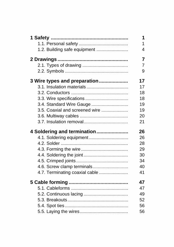
1 Safety 1........................................................1.1. Personal safety 1.......................................1.2. Building safe equipment 4.........................
2 Drawings 7...................................................2.1. Types of drawing 7....................................2.2. Symbols 9..................................................
3 Wire types and preparation 17.....................3.1. Insulation materials 17.................................3.2. Conductors 18.............................................3.3. Wire specifications 18..................................3.4. Standard Wire Gauge 19.............................3.5. Coaxial and screened wire 19.....................3.6. Multiway cables 20......................................3.7. Insulation removal 21...................................
4 Soldering and termination 26.......................4.1. Soldering equipment 26...............................4.2. Solder 28.....................................................4.3. Forming the wire 29.....................................4.4. Soldering the joint 30...................................4.5. Crimped joints 34.........................................4.6. Screw clamp terminals 40............................4.7. Terminating coaxial cable 41.......................
5 Cable forming 47...........................................5.1. Cableforms 47.............................................5.2. Continuous lacing 49...................................5.3. Breakouts 52................................................5.4. Spot ties 56..................................................5.5. Laying the wires 56......................................
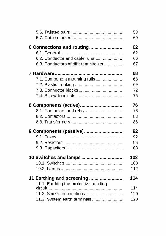
5.6. Twisted pairs 58...........................................5.7. Cable markers 60........................................
6 Connections and routing 62.........................6.1. General 62...................................................6.2. Conductor and cable runs 66.......................6.3. Conductors of different circuits 67...............
7 Hardware 68...................................................7.1. Component mounting rails 68......................7.2. Plastic trunking 69.......................................7.3. Connector blocks 72....................................7.4. Screw terminals 75......................................
8 Components (active) 76................................8.1. Contactors and relays 76.............................8.2. Contactors 83..............................................8.3. Transformers 88..........................................
9 Components (passive) 92.............................9.1. Fuses 92......................................................9.2. Resistors 96.................................................9.3. Capacitors 103...............................................
10 Switches and lamps 108...............................10.1. Switches 108...............................................10.2. Lamps 112...................................................
11 Earthing and screening 114.........................11.1. Earthing the protective bondingcircuit 114.............................................................11.2. Screen connections 120..............................11.3. System earth terminals 120.........................

12 PLC wiring 122..............................................12.1. Installation 122.............................................12.2. Power supply wiring 123..............................12.3. Earthing 123................................................12.4. Wiring of inputs and outputs 124.................
1. SAFETY
1.1. Personal safety
Concern for your own safety as well as the safety of others should always be on your mind. Most safetyprocedures are common sense but, because some hazards are not obvious, there are regulations born outof experience which are designed to make the workplace safer.
There are two aspects of safety which concern us in the assembly of electrical equipment and controlpanels.
The first concerns your own personal safety. In the words of the Health and Safety Regulations:
� the need to use safe working practices and safety equipment to avoid the risk of injury to yourselfand to others in the course of your work.
While it is beyond the scope of this book to cover the detail of all the safety precautions and safe workingpractices which should be adopted, there are some general points which can be noted.
� Safety equipment, e.g. goggles, gloves, etc., should be provided and must be used where they areappropriate.
� The onus is on you to use the safety equipment provided by your company. Any damage to safetygear should be reported. Safe working practices are part of any job and you should always learn andadopt them as a natural way of working.
� Don’t take shortcuts which compromise your safety, or that of anybody else.
� You should make yourself aware of the procedures used at your place of work to prevent accidentsand to deal with common incidents.
� You should know how to isolate electric supplies and how to work safely on electrical circuits.
1.1.1. Accidents
� Know how to contact the correct person – thedesignated first aider – for help.
� Find out the location of the nearest first aidbox.
� Know how to isolate electric supplies and howto release a person safely from contact withelectricity.
1
1. SAFETY
1.1.2. FireBefore commencing work on electric plant, youshould know:
� Where is the nearest fire alarm activator, fire exitand fire extinguisher?
� Are the fire exits clear of equipment orrubbish?
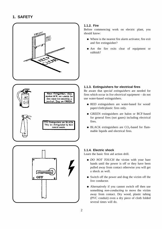
1.1.3. Extinguishers for electrical firesBe aware that special extinguishers are needed forfires which occur in live electrical equipment – do notuse water-based extinguishers.
� RED extinguishers are water-based for wood/paper/cloth/plastic fires only.
� GREEN extinguishers are halon or BCF-basedfor general fires (not gases) including electricalfires.
� BLACK extinguishers are CO2-based for flam-mable liquids and electrical fires.
1.1.4. Electric shockLearn the basic first aid action drill.
� DO NOT TOUCH the victim with your barehands until the power is off or they have beenpulled away from contact otherwise you will geta shock as well.
� Switch off the power and drag the victim off thelive conductor.
� Alternatively if you cannot switch off then usesomething non-conducting to move the victimaway from contact. Dry wood, plastic tubing(PVC conduit) even a dry piece of cloth foldedseveral times will do.
2
1. SAFETY
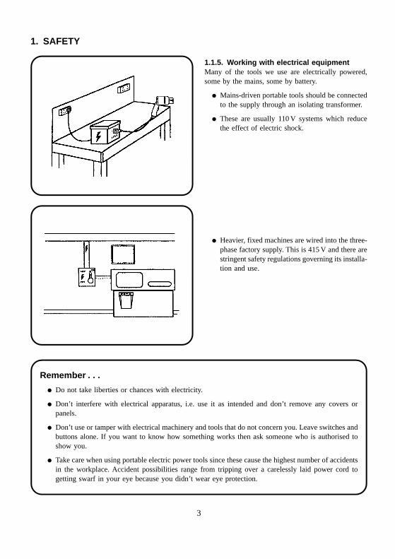
1.1.5. Working with electrical equipmentMany of the tools we use are electrically powered,some by the mains, some by battery.
� Mains-driven portable tools should be connectedto the supply through an isolating transformer.
� These are usually 110 V systems which reducethe effect of electric shock.
� Heavier, fixed machines are wired into the three-phase factory supply. This is 415 V and there arestringent safety regulations governing its installa-tion and use.
Remember . . .
� Do not take liberties or chances with electricity.
� Don’t interfere with electrical apparatus, i.e. use it as intended and don’t remove any covers orpanels.
� Don’t use or tamper with electrical machinery and tools that do not concern you. Leave switches andbuttons alone. If you want to know how something works then ask someone who is authorised toshow you.
� Take care when using portable electric power tools since these cause the highest number of accidentsin the workplace. Accident possibilities range from tripping over a carelessly laid power cord togetting swarf in your eye because you didn’t wear eye protection.
3
1. SAFETY
1.2. Building safe equipment
The second aspect of safety concerns the requirementto:
� design, construct and use electrical equipment sothat it is safe and does not give rise to dangereven should a fault occur.
The designer of the equipment will have taken intoaccount all these concerns in specifying the parts to beused, the wire types and colours, the type of enclosureand so on. Our part comes in ensuring that:
� no parts are to be substituted without anengineering change notice;
� manufacturers’ instructions for any componentmust be followed.
Both of these aspects are statutory requirements laiddown in law in a number of regulations.
1.2.1. The Health and Safety at Work Act(HSAW)This is a wide-ranging Act of Parliament covering allaspects of safety at work. It has gradually replaced theFactories Act.
The HSAW allows for the introduction of regulations tocontrol particular aspects of safety at work. Theseregulations, which must be complied with, are oftenproduced because of European Directives, which inturn are designed to harmonise the safe working con-ditions for all members of the European Community.
Among the many regulations within the Act, somehave a direct influence on the machinery controlpanels which we are interested in, for example:
� The Electricity at Work Regulations 1989.
� The Provision and Use of Work Equipment.
� The Supply of Machinery (Safety) Regulations.
� The Electrical Equipment (Safety) Regulations.
These affect other areas of safety besides those whichconcern us here and it is outside the scope of this bookto go into any real detail on them. However, you mayfind it useful to consider how they affect the way webuild these panels and the components we use in them.
1.2.2. StandardsA standard is a document specifying nationally orinternationally agreed properties for manufacturedgoods and equipment.
Regulations and standards are two different things:regulations are the law and must be complied with;standards on the other hand are advisory. They areclosely linked together.
Equipment sold in the EEC must be ‘CE marked’ toshow that it complies with the regulations that areconcerned with its safety. As part of this process themanufacturer must show how the risks and hazardsthat the equipment will present have been overcome orprotected against. This information is placed in theTechnical Document of the equipment so that it can beinspected should there be a query by the authoritiesregarding the equipment’s safety or performance.
The best way to show compliance with a regulation isto use recognised standards in the design and con-struction of the product, thereby fulfilling the require-ments of the regulation.
The British Standards Institute (BSI), as well as otherEuropean and international bodies, publish standardswhich give recommendations and guidance on –amongst other things – the selection and use of variouselectrical components and cables.
There are three types of standards that are important tous:
� British Standards (BS),
� European Harmonised Standards (EN or BS EN),
� International Standards (IEC).
These are of course mainly the concern of the designerbut it is as well to be aware that they exist, as it mayexplain why one component is used instead of anotherand why only those components designated in theparts list must be used.
Standards of most importance to us are:
� BS EN 60204 – Safety of Machinery – ElectricalEquipment of Machines,
� BS EN 60947 (IEC947) – Low Voltage Switch-gear and Controlgear (7 Parts).
4
1. SAFETY
BS EN 60204 covers the way in which the electricalequipment should be constructed and includes every-thing from the selection of components, through thesizes, types and colour of the wiring, to the electricaltests that should be done on the finished equipment.Within BS EN 60204 there are references to otherstandards, including BS EN 60947, that will give moredetail on individual parts or components.
BS EN 60947 and the international standard IEC 947are in seven parts, giving the specification and otherrequirements of the individual components we willuse in the equipment.
� Part 1: General Requirements. Defines the rulesof a general nature to obtain uniformity inrequirements and tests.
Each of the following parts deals mainly with thecharacteristics, conditions for operation, methods fortesting and marking requirements of the variouselectrical components.
� Part 2: Circuit-breakers.
� Part 3: Switches, disconnectors, switch-discon-nectors and fuse combination units.
� Part 4: Contactors and motor starters includingshort circuit and overload protection devices.
� Part 5: Control circuit devices and switchingelements.
� Part 6: Multiple function equipment such as thatused for automatic emergency power switching.
� Part 7: Ancillary equipment such as terminalblocks used to connect copper conductors.
Basically our control equipment panels should be builtto conform to the requirements of BS EN 60204 usingcomponents manufactured to conform to the require-ments of BS EN 60947 and other related componentstandards and approvals.
An approved component is one whose manufactureand performance has been checked and proven to meetthe specifications set by the standards authority of anindividual country. For example, a part approved inthe UK would be ‘BS approved’. These approvals maybe important if the equipment is to be exported.
Some other standards authorities are:
� USA ANSI – approvals are made by theUnderwriters Laboratory and marked UL.
� Canada, CSA.
� Denmark, DEMKO.
� Italy, CEI.
� Norway, NEMKO.
� Germany, DIN/VDE.
� France, NF/UTE.
� Europe, CENELEC.
Some other BSI documents
� PD 2754: Parts 1 and 2. Published document.Construction of electrical equipment for protec-tion against electric shock. Part 1 deals with theclassification of electrical and electronic equip-ment with regard to protection against electricshock, for example whether it is earthed, doubleinsulated or uses a safe, low voltage supply. Part2 is a more detailed guide to the requirements ofthe various classes as defined in Part 1.
� BS 7452: Specification for transformers of thetype used in control panels. Equivalent to IEC989: Control transformer specification.
� BS 3939: Graphical symbols. Provides compre-hensive details of the symbols to be used inelectrical, electronic and telecommunication dia-grams. It is published in 12 parts and is broadlythe same as EN 617 – Parts 2 to 12.
� BS EN 60073: Colours for indicator lamps, pushbuttons, etc. Provides a general set of rules forthe use of certain colours, shapes, positioningrequirements of indicators and actuators toincrease the safety and operational efficiency ofequipment. BS EN 60204 also provides guide-lines specific to the electrical controls formachinery.
� BS EN 60529: Specification for classification ofdegrees of protection provided by electricalenclosures. Also known as ‘IP Codes’, it uses a
5
1. SAFETY
two or three digit number to define to whatdegree the enclosure is sealed to protect thecontents against dust, moisture and similardamaging substances.
� BS 6231: Specification for PVC-insulated cablefor switchgear and controlgear wiring. This dealswith the requirements for the wires and cablesused in the wiring of control panels up to600 V/1000 V.
1.2.3. The IEE regulations (BS 7671)The Institute of Electrical Engineers publishes itsRegulations for Electrical Installations, which coverthe design, selection and construction of electricalinstallations in buildings generally, and provide guid-ance for safety in the design and construction of
electrical equipment. Although mainly concerned withelectrical systems in buildings, the information isapplicable to machine control panels because they willbe connected to the building’s electrical system. Theseare now published as BS 7671.
In addition there are:
� Guidance Notes from the Health and SafetyExecutive.
� Specifications and Regulations from the Depart-ment of Trade and Industry, BSI and the Instituteof Electrical Engineers.
You may be interested to know that all the standardsreferred to here concern ‘low voltage’ equipment.Low voltages as defined by the IEE are those up toand including 1000 volts AC or 1500 volts DC.
6
2. DRAWINGS
2.1. Types of drawing
We use drawings to convey the information about apiece of equipment in a form which all those involvedin its production, installation and service will under-stand. To make this possible, standard drawingconventions have been adopted by most companies.
� This book will emphasise the British Standardsymbols as defined in BS 3939. Other symbolswhich may be in common use will also beshown.
The information we need to be able to assemble theequipment will be only one item in the set of drawingsand schedules which make up the complete design.
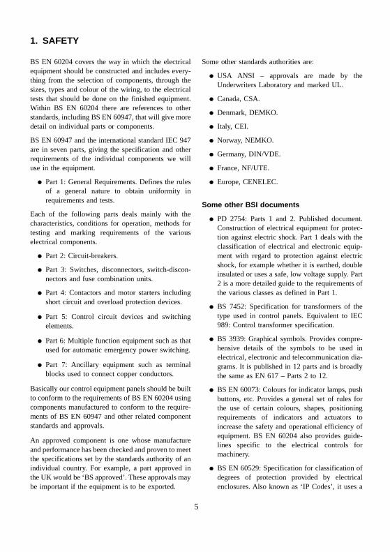
2.1.1. Circuit diagramThis shows how the electrical components are con-nected together and uses:
� symbols to represent the components;
� lines to represent the functional conductors orwires which connect them together.
A circuit drawing is derived from a block or functionaldiagram (see 2.1.4.). It does not generally bear anyrelationship to the physical shape, size or layout of theparts and although you could wire up an assembly fromthe information given in it, they are usually intended toshow the detail of how an electrical circuit works.
2.1.2. Wiring diagramThis is the drawing which shows all the wiringbetween the parts, such as:
� control or signal functions;
� power supplies and earth connections;
� termination of unused leads, contacts;
� interconnection via terminal posts, blocks, plugs,sockets, lead-throughs.
It will have details, such as the terminal identificationnumbers which enable us to wire the unit together.Parts of the wiring diagram may simply be shown asblocks with no indication as to the electrical compo-nents inside. These are usually sub-assemblies madeseparately, i.e. pre-assembled circuits or modules.
7
2. DRAWINGS
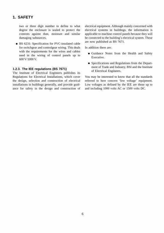
2.1.3. Wiring scheduleThis defines the wire reference number, type (size andnumber of conductors), length and the amount ofinsulation stripping required for soldering.
In complex equipment you may also find a table ofinterconnections which will give the starting andfinishing reference points of each connection as wellas other important information such as wire colour,ident marking and so on.
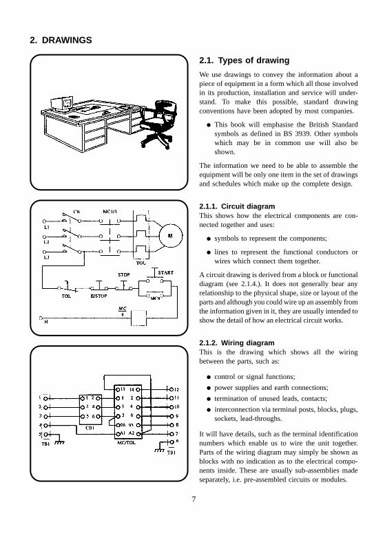
2.1.4. Block diagramThe block diagram is a functional drawing which isused to show and describe the main operatingprinciples of the equipment and is usually drawnbefore the circuit diagram is started.
It will not give any real detail of the actual wiringconnections or even the smaller components and so isonly of limited interest to us in the wiring of controlpanels and equipment.
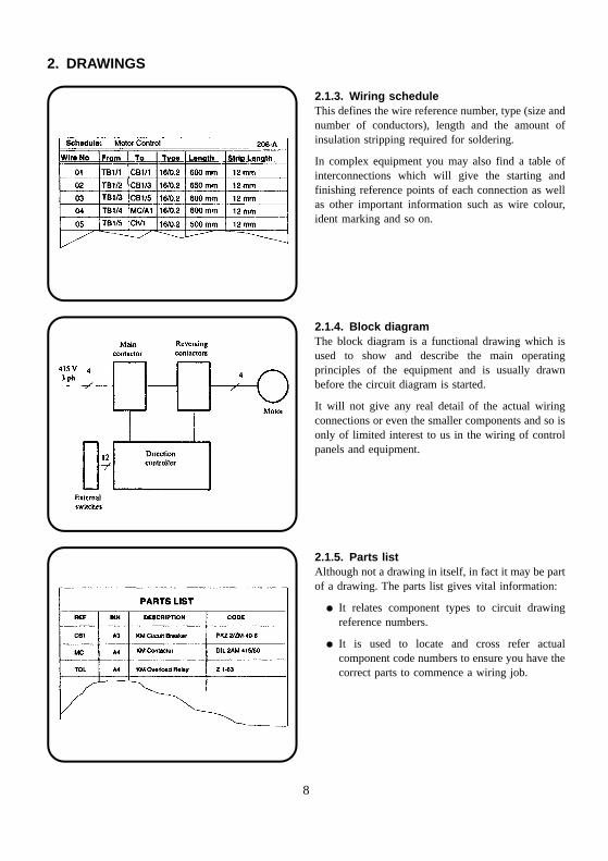
2.1.5. Parts listAlthough not a drawing in itself, in fact it may be partof a drawing. The parts list gives vital information:
� It relates component types to circuit drawingreference numbers.
� It is used to locate and cross refer actualcomponent code numbers to ensure you have thecorrect parts to commence a wiring job.
8
2. DRAWINGS
2.2. Symbols
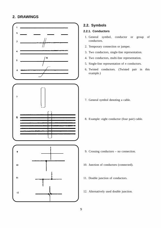
2.2.1. Conductors
1. General symbol, conductor or group ofconductors.
2. Temporary connection or jumper.
3. Two conductors, single-line representation.
4. Two conductors, multi-line representation.
5. Single-line representation of n conductors.
6. Twisted conductors. (Twisted pair in thisexample.)
7. General symbol denoting a cable.
8. Example: eight conductor (four pair) cable.
9. Crossing conductors – no connection.
10. Junction of conductors (connected).
11. Double junction of conductors.
12. Alternatively used double junction.
9
2. DRAWINGS
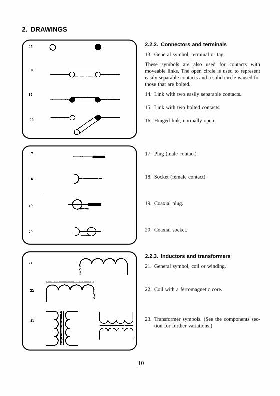
2.2.2. Connectors and terminals
13. General symbol, terminal or tag.
These symbols are also used for contacts withmoveable links. The open circle is used to representeasily separable contacts and a solid circle is used forthose that are bolted.
14. Link with two easily separable contacts.
15. Link with two bolted contacts.
16. Hinged link, normally open.
17. Plug (male contact).
18. Socket (female contact).
19. Coaxial plug.
20. Coaxial socket.
2.2.3. Inductors and transformers
21. General symbol, coil or winding.
22. Coil with a ferromagnetic core.
23. Transformer symbols. (See the components sec-tion for further variations.)
10
2. DRAWINGS
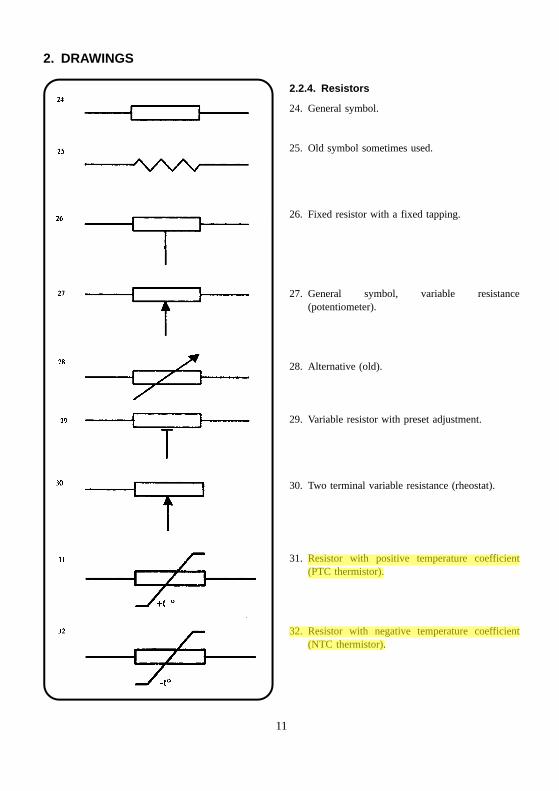
2.2.4. Resistors
24. General symbol.
25. Old symbol sometimes used.
26. Fixed resistor with a fixed tapping.
27. General symbol, variable resistance(potentiometer).
28. Alternative (old).
29. Variable resistor with preset adjustment.
30. Two terminal variable resistance (rheostat).
31. Resistor with positive temperature coefficient(PTC thermistor).
32. Resistor with negative temperature coefficient(NTC thermistor).
11
2. DRAWINGS
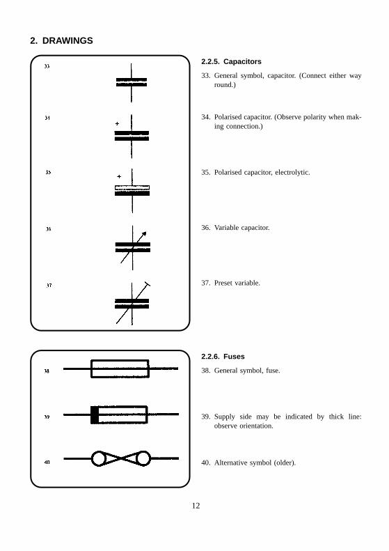
2.2.5. Capacitors
33. General symbol, capacitor. (Connect either wayround.)
34. Polarised capacitor. (Observe polarity when mak-ing connection.)
35. Polarised capacitor, electrolytic.
36. Variable capacitor.
37. Preset variable.
2.2.6. Fuses
38. General symbol, fuse.
39. Supply side may be indicated by thick line:observe orientation.
40. Alternative symbol (older).
12
2. DRAWINGS
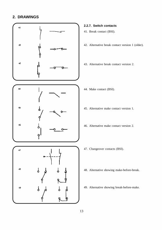
2.2.7. Switch contacts
41. Break contact (BSI).
42. Alternative break contact version 1 (older).
43. Alternative break contact version 2.
44. Make contact (BSI).
45. Alternative make contact version 1.
46. Alternative make contact version 2.
47. Changeover contacts (BSI).
48. Alternative showing make-before-break.
49. Alternative showing break-before-make.
13
2. DRAWINGS
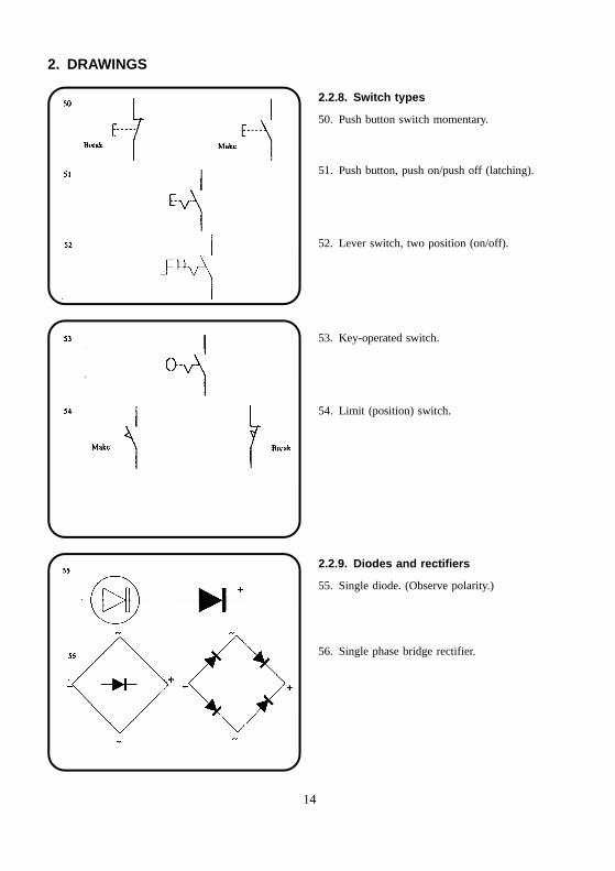
2.2.8. Switch types
50. Push button switch momentary.
51. Push button, push on/push off (latching).
52. Lever switch, two position (on/off).
53. Key-operated switch.
54. Limit (position) switch.
2.2.9. Diodes and rectifiers
55. Single diode. (Observe polarity.)
56. Single phase bridge rectifier.
14
2. DRAWINGS
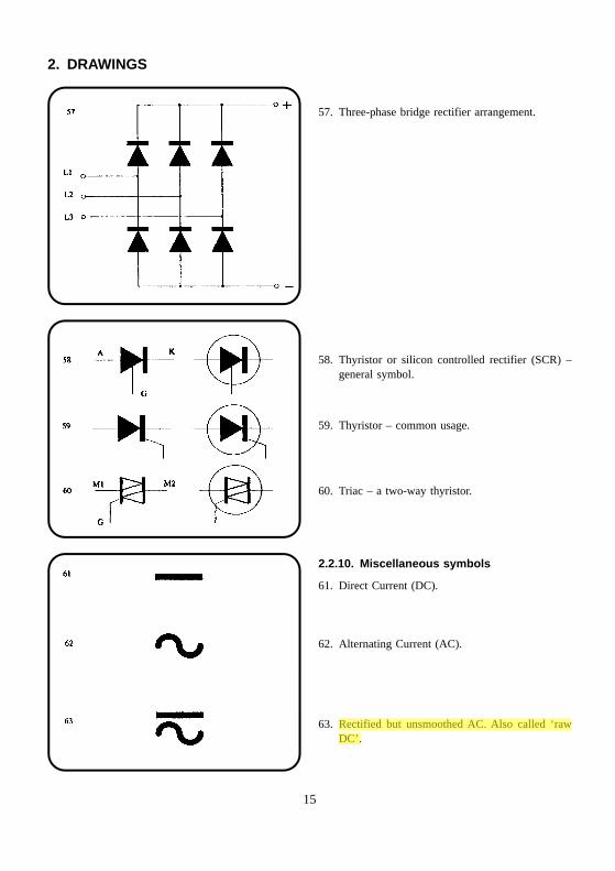
57. Three-phase bridge rectifier arrangement.
58. Thyristor or silicon controlled rectifier (SCR) –general symbol.
59. Thyristor – common usage.
60. Triac – a two-way thyristor.
2.2.10. Miscellaneous symbols
61. Direct Current (DC).
62. Alternating Current (AC).
63. Rectified but unsmoothed AC. Also called ‘rawDC’.
15
2. DRAWINGS
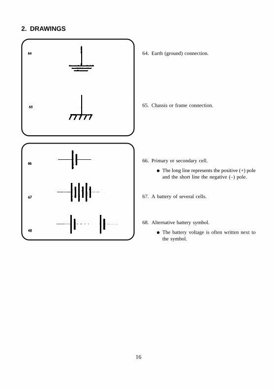
64. Earth (ground) connection.
65. Chassis or frame connection.
66. Primary or secondary cell.
� The long line represents the positive (+) poleand the short line the negative (–) pole.
67. A battery of several cells.
68. Alternative battery symbol.
� The battery voltage is often written next tothe symbol.
16
3. WIRE TYPES AND PREPARATION
Introduction
Electrical equipment uses a wide variety of wire andcable types and it is up to us to be able to correctlyidentify and use the wires which have been specified.The wrong wire types will cause operational problemsand could render the unit unsafe. Such factors include:
� the insulation material;
� the size of the conductor;
� what it’s made of;
� whether it’s solid or stranded and flexible.
These are all considerations which the designer has totake into account to suit the final application of theequipment.
A conductor is a material which will allow an electriccurrent to flow easily. In the case of a wire connection,it needs to be a very good conductor. Good conductorsinclude most metals. The most common conductorused in wire is copper, although you may come acrossothers such as aluminium.
An insulator on the other hand is a material whichdoes not allow an electric current to flow. Rubber andmost plastics are insulators.
3.1. Insulation materials
Wires and cables (conductors) are insulated and pro-tected by a variety of materials (insulators) each onehaving its own particular properties. The type of mater-ial used will be determined by the designer who willtake into account the environment in which a controlpanel or installation is expected to operate as well as theapplication of individual wires within the panel.
As part of the insulating function, a material may haveto withstand without failing:
� extremes of current or temperature;
� a corrosive or similarly harsh environment;
� higher voltages than the rest of the circuit.
Because of these different properties and applications,it is essential that you check the wiring specificationfor the correct type to use.
PVC (Polyvinylchloride)This is the most commonly used general-purposeinsulation. It will soften at higher temperatures andwill permanently deform. Temperature range is –20°Cto +75°C. This means that a soldering iron will melt iteasily.
PolytheneA wax-like, translucent material which is used mainlyfor high voltage and high frequency applications.
PTFE (Polytetrafluoroethylene)Similar to polythene but used for higher temperatureenvironments (up to about +250°C).
Silicone rubberAppears similar to natural rubber but feels smoother.It is used in harsh environments where elevatedtemperatures, radiation or chemical vapours areencountered.
PolyurethaneGenerally found as a thin coating on copper wire.Used in transformer windings and similar applica-tions. Some are ‘self fluxing’ during soldering but maygive off harmful fumes.
EnamelUsed like polyurethane as a thin layer on copper wires.
Glass fibreUsually woven it is used for extremely high tem-perature applications. Wear gloves when using glassfibres; they are a skin irritant.
Other typesThere are other less common materials used in somespecialised cables and you should become familiarwith those used at your workplace. Some wires areinsulated with Low Smoke and Fume (LSF) materials,the use of which is self-evident. These are halogenfree, with Polyolefin and Polyethylene being twocommon materials.
17
3. WIRE TYPES AND PREPARATION
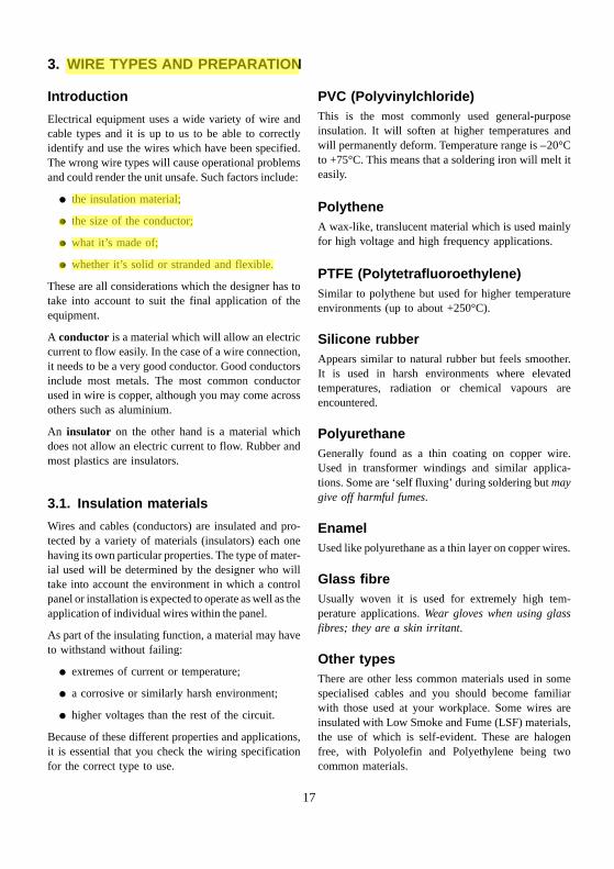
3.2. Conductors
The conductor can be a single solid wire or made upof a number of thin strands.
� Solid or single-stranded wire is not very flexibleand is used where rigid connections are accept-able or preferred – usually in high currentapplications in power switching contractors. Itmay be uninsulated.
� Stranded wire is flexible and most interconnec-tions between components are made with it.
� Braided wire: see Sections 3.5 and 9.1.2.
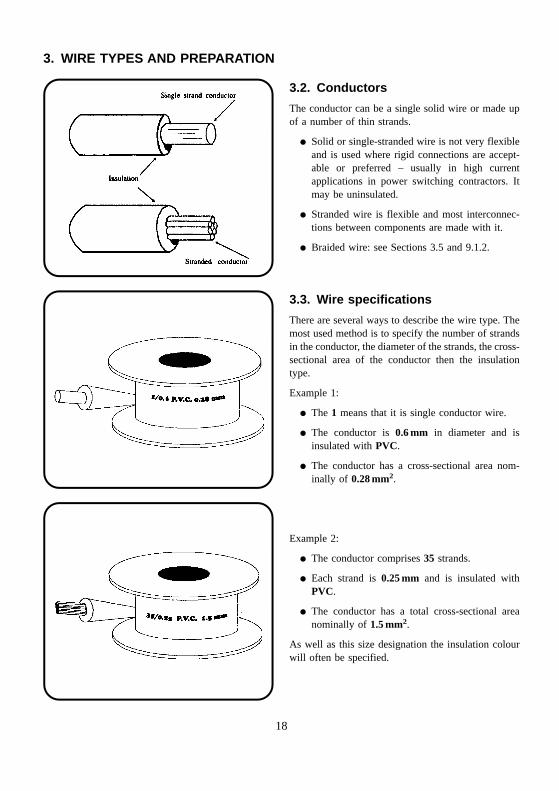
3.3. Wire specifications
There are several ways to describe the wire type. Themost used method is to specify the number of strandsin the conductor, the diameter of the strands, the cross-sectional area of the conductor then the insulationtype.
Example 1:
� The 1 means that it is single conductor wire.
� The conductor is 0.6 mm in diameter and isinsulated with PVC.
� The conductor has a cross-sectional area nom-inally of 0.28 mm2.
Example 2:
� The conductor comprises 35 strands.
� Each strand is 0.25 mm and is insulated withPVC.
� The conductor has a total cross-sectional areanominally of 1.5 mm2.
As well as this size designation the insulation colourwill often be specified.
18
3. WIRE TYPES AND PREPARATION
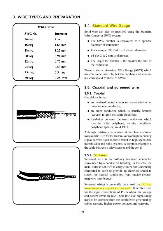
3.4. Standard Wire Gauge
Solid wire can also be specified using the StandardWire Gauge or SWG system.
� The SWG number is equivalent to a specificdiameter of conductor.
� For example; 30 SWG is 0.25 mm diameter.
� 14 SWG is 2 mm in diameter.
� The larger the number – the smaller the size ofthe conductor.
There is also an American Wire Gauge (AWG) whichuses the same principle, but the numbers and sizes donot correspond to those of SWG.
3.5. Coaxial and screened wire
3.5.1. CoaxialCoaxial cable has:
� an insulated central conductor surrounded by anouter tubular conductor;
� an outer conductor which is usually braided(woven) to give the cable flexibility;
� insulation between the two conductors whichmay be solid polythene, cellular polythene,polythene spacers, solid PTFE.
Although relatively expensive, it has low electricallosses and is used for the transmission of high frequencysignal currents such as those found in high speed datatransmission and radio systems. A common example isthe cable between a television set and the aerial.
3.5.2. ScreenedScreened wire is an ordinary insulated conductorsurrounded by a conductive braiding. In this case themetal outer is not used to carry current but is normallyconnected to earth to provide an electrical shield toscreen the internal conductors from outside electro-magnetic interference.
Screened wiring is generally only used for DC andlower frequency signals such as audio. It is often usedfor the input connections of PLCs where the voltageand current levels are low. These low level signals mayneed to be screened from the interference generated bycables carrying higher power voltages and currents.
19
3. WIRE TYPES AND PREPARATION
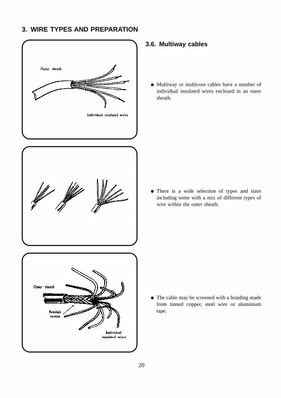
3.6. Multiway cables
� Multiway or multicore cables have a number ofindividual insulated wires enclosed in an outersheath.
� There is a wide selection of types and sizesincluding some with a mix of different types ofwire within the outer sheath.
� The cable may be screened with a braiding madefrom tinned copper, steel wire or aluminiumtape.
20
3. WIRE TYPES AND PREPARATION
3.7. Insulation removal
IntroductionThe removal of insulation from wires and cables isone of those tasks which, like soldering or crimping, isa major part of assembly work. There are manytechniques used within the industry, using toolsranging from the simple hand-operated strippers toautomatic, motorised types.
Hand-operated strippers fall into two main categories:those which are adjustable and those which are not.Within the non-adjustable types are some which haveflexible jaws and will strip a range of wire sizes, whileothers have a series of cutting holes for each wire size.
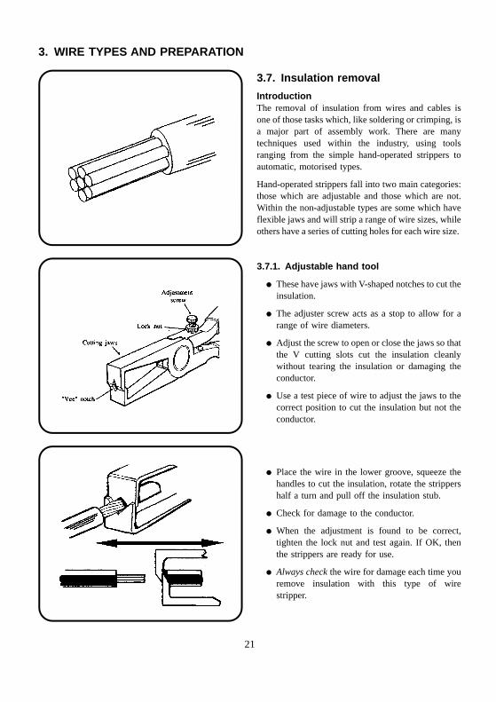
3.7.1. Adjustable hand tool
� These have jaws with V-shaped notches to cut theinsulation.
� The adjuster screw acts as a stop to allow for arange of wire diameters.
� Adjust the screw to open or close the jaws so thatthe V cutting slots cut the insulation cleanlywithout tearing the insulation or damaging theconductor.
� Use a test piece of wire to adjust the jaws to thecorrect position to cut the insulation but not theconductor.
� Place the wire in the lower groove, squeeze thehandles to cut the insulation, rotate the strippershalf a turn and pull off the insulation stub.
� Check for damage to the conductor.
� When the adjustment is found to be correct,tighten the lock nut and test again. If OK, thenthe strippers are ready for use.
� Always check the wire for damage each time youremove insulation with this type of wirestripper.
21
3. WIRE TYPES AND PREPARATION
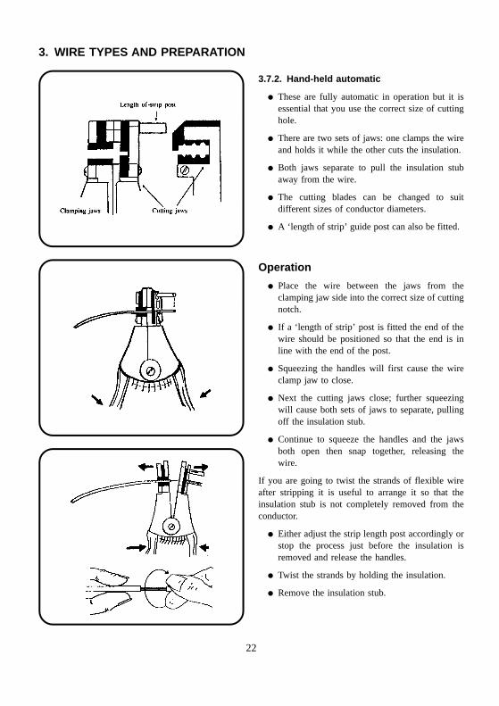
3.7.2. Hand-held automatic
� These are fully automatic in operation but it isessential that you use the correct size of cuttinghole.
� There are two sets of jaws: one clamps the wireand holds it while the other cuts the insulation.
� Both jaws separate to pull the insulation stubaway from the wire.
� The cutting blades can be changed to suitdifferent sizes of conductor diameters.
� A ‘length of strip’ guide post can also be fitted.
Operation
� Place the wire between the jaws from theclamping jaw side into the correct size of cuttingnotch.
� If a ‘length of strip’ post is fitted the end of thewire should be positioned so that the end is inline with the end of the post.
� Squeezing the handles will first cause the wireclamp jaw to close.
� Next the cutting jaws close; further squeezingwill cause both sets of jaws to separate, pullingoff the insulation stub.
� Continue to squeeze the handles and the jawsboth open then snap together, releasing thewire.
If you are going to twist the strands of flexible wireafter stripping it is useful to arrange it so that theinsulation stub is not completely removed from theconductor.
� Either adjust the strip length post accordingly orstop the process just before the insulation isremoved and release the handles.
� Twist the strands by holding the insulation.
� Remove the insulation stub.
22
3. WIRE TYPES AND PREPARATION
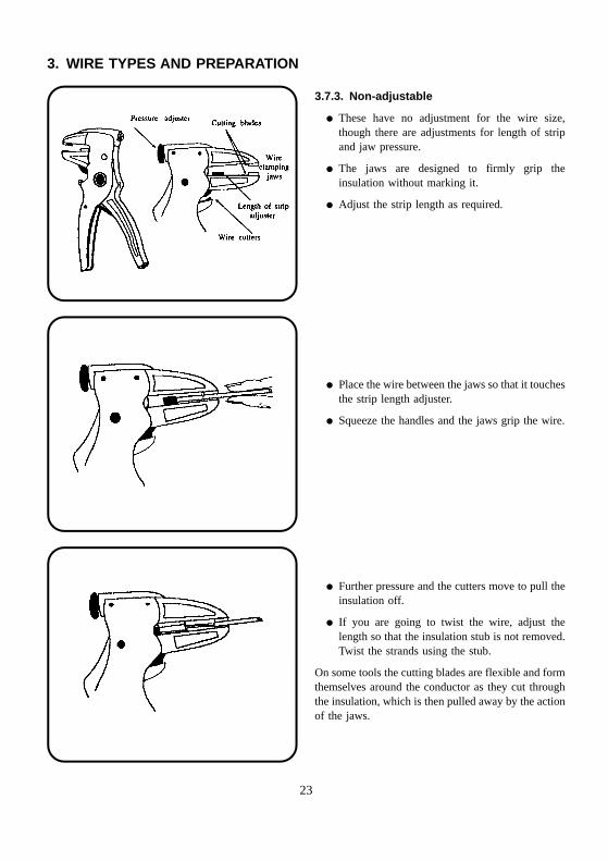
3.7.3. Non-adjustable
� These have no adjustment for the wire size,though there are adjustments for length of stripand jaw pressure.
� The jaws are designed to firmly grip theinsulation without marking it.
� Adjust the strip length as required.
� Place the wire between the jaws so that it touchesthe strip length adjuster.
� Squeeze the handles and the jaws grip the wire.
� Further pressure and the cutters move to pull theinsulation off.
� If you are going to twist the wire, adjust thelength so that the insulation stub is not removed.Twist the strands using the stub.
On some tools the cutting blades are flexible and formthemselves around the conductor as they cut throughthe insulation, which is then pulled away by the actionof the jaws.
23
3. WIRE TYPES AND PREPARATION
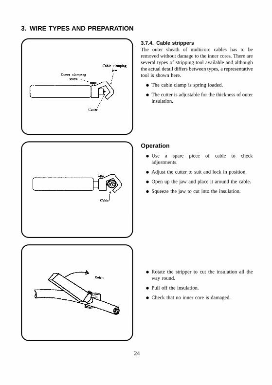
3.7.4. Cable strippersThe outer sheath of multicore cables has to beremoved without damage to the inner cores. There areseveral types of stripping tool available and althoughthe actual detail differs between types, a representativetool is shown here.
� The cable clamp is spring loaded.
� The cutter is adjustable for the thickness of outerinsulation.
Operation
� Use a spare piece of cable to checkadjustments.
� Adjust the cutter to suit and lock in position.
� Open up the jaw and place it around the cable.
� Squeeze the jaw to cut into the insulation.
� Rotate the stripper to cut the insulation all theway round.
� Pull off the insulation.
� Check that no inner core is damaged.
24
3. WIRE TYPES AND PREPARATION
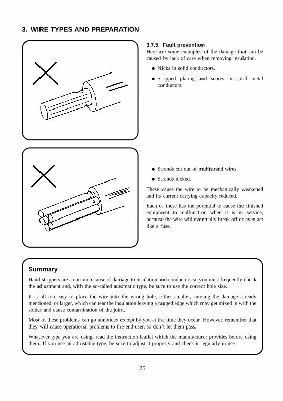
3.7.5. Fault preventionHere are some examples of the damage that can becaused by lack of care when removing insulation.
� Nicks in solid conductors.
� Stripped plating and scores in solid metalconductors.
� Strands cut out of multistrand wires.
� Strands nicked.
These cause the wire to be mechanically weakenedand its current carrying capacity reduced.
Each of these has the potential to cause the finishedequipment to malfunction when it is in service,because the wire will eventually break off or even actlike a fuse.
Summary
Hand strippers are a common cause of damage to insulation and conductors so you must frequently checkthe adjustment and, with the so-called automatic type, be sure to use the correct hole size.
It is all too easy to place the wire into the wrong hole, either smaller, causing the damage alreadymentioned, or larger, which can tear the insulation leaving a ragged edge which may get mixed in with thesolder and cause contamination of the joint.
Most of these problems can go unnoticed except by you at the time they occur. However, remember thatthey will cause operational problems to the end-user, so don’t let them pass.
Whatever type you are using, read the instruction leaflet which the manufacturer provides before usingthem. If you use an adjustable type, be sure to adjust it properly and check it regularly in use.
25
4. SOLDERING AND TERMINATION
4.1. Soldering equipment
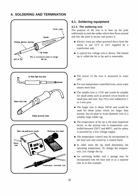
4.1.1. The soldering ironThe purpose of the iron is to heat up the jointsufficiently to melt the solder which then flows aroundand into the joint to secure and protect it.
� Electric irons are either powered direct from themains or use 12 V or 24 V supplied by atransformer unit.
� A typical low voltage iron is shown. The heatedtip is called the bit or tip and is removable.
� The power of the iron is measured in watts(W).
� For non-temperature controlled irons, more wattsmeans more heat.
� The smaller iron is 15 W and would be suitablefor small joints such as printed circuit boards orsmall pins and wire. Say 7/0.2 wire soldered to 1or 2 mm pins.
� The larger iron is about 100 W and would beused for those joints which are larger thannormal. Say tin plate or 4 mm diameter wire to asuitably large solder tag.
� The temperature of the tip is the most importantfactor, so the normal iron is temperature con-trolled between 250°C and 400°C, and for safetyis powered by a low voltage supply.
� The temperature control may be incorporated inthe base unit and varied by a control knob.
� In other irons the tip itself determines theoperating temperature. To change the tempera-ture, you change the tip.
� An enclosing holder and a sponge may beincorporated into the base unit or as a separateunit as in this example.
26
4. SOLDERING AND TERMINATION
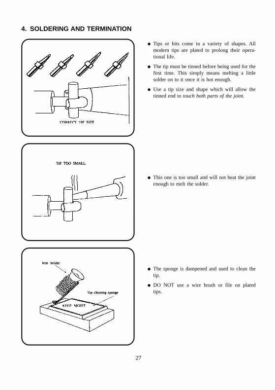
� Tips or bits come in a variety of shapes. Allmodern tips are plated to prolong their opera-tional life.
� The tip must be tinned before being used for thefirst time. This simply means melting a littlesolder on to it once it is hot enough.
� Use a tip size and shape which will allow thetinned end to touch both parts of the joint.
� This one is too small and will not heat the jointenough to melt the solder.
� The sponge is dampened and used to clean thetip.
� DO NOT use a wire brush or file on platedtips.
27
4. SOLDERING AND TERMINATION
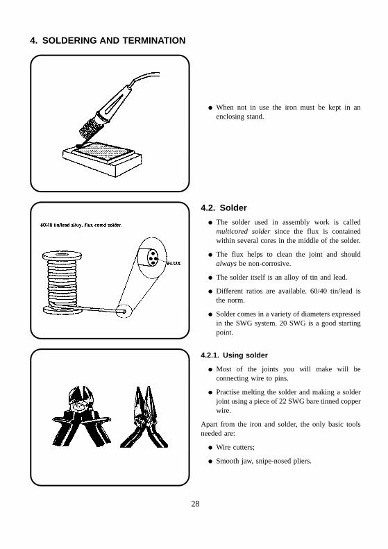
� When not in use the iron must be kept in anenclosing stand.
4.2. Solder
� The solder used in assembly work is calledmulticored solder since the flux is containedwithin several cores in the middle of the solder.
� The flux helps to clean the joint and shouldalways be non-corrosive.
� The solder itself is an alloy of tin and lead.
� Different ratios are available. 60/40 tin/lead isthe norm.
� Solder comes in a variety of diameters expressedin the SWG system. 20 SWG is a good startingpoint.
4.2.1. Using solder
� Most of the joints you will make will beconnecting wire to pins.
� Practise melting the solder and making a solderjoint using a piece of 22 SWG bare tinned copperwire.
Apart from the iron and solder, the only basic toolsneeded are:
� Wire cutters;
� Smooth jaw, snipe-nosed pliers.
28
4. SOLDERING AND TERMINATION
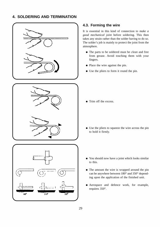
4.3. Forming the wire
It is essential in this kind of connection to make agood mechanical joint before soldering. This thentakes any strain rather than the solder having to do so.The solder’s job is mainly to protect the joint from theatmosphere.
� The parts to be soldered must be clean and freefrom grease. Avoid touching them with yourfingers.
� Place the wire against the pin.
� Use the pliers to form it round the pin.
� Trim off the excess.
� Use the pliers to squeeze the wire across the pinto hold it firmly.
� You should now have a joint which looks similarto this.
� The amount the wire is wrapped around the pincan be anywhere between 180° and 350° depend-ing upon the application of the finished unit.
� Aerospace and defence work, for example,requires 350°.
29
4. SOLDERING AND TERMINATION
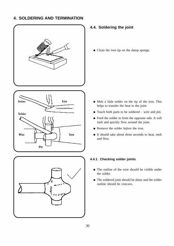
4.4. Soldering the joint
� Clean the iron tip on the damp sponge.
� Melt a little solder on the tip of the iron. Thishelps to transfer the heat to the joint.
� Touch both parts to be soldered – wire and pin.
� Feed the solder in from the opposite side. It willmelt and quickly flow around the joint.
� Remove the solder before the iron.
� It should take about three seconds to heat, meltand flow.
4.4.1. Checking solder joints
� The outline of the wire should be visible underthe solder.
� The soldered joint should be shiny and the solderoutline should be concave.
30
4. SOLDERING AND TERMINATION
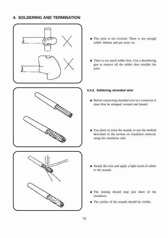
� This joint is not covered. There is not enoughsolder. Reheat and put more on.
� There is too much solder here. Use a desolderinggun to remove all the solder then resolder thejoint.
4.4.2. Soldering stranded wire
� Before connecting stranded wire to a connector itmust first be stripped, twisted and tinned.
� Use pliers to twist the strands or use the methoddescribed in the section on insulation removal,using the insulation stub.
� Steady the wire and apply a light touch of solderto the strands.
� The tinning should stop just short of theinsulation.
� The outline of the strands should be visible.
31
4. SOLDERING AND TERMINATION
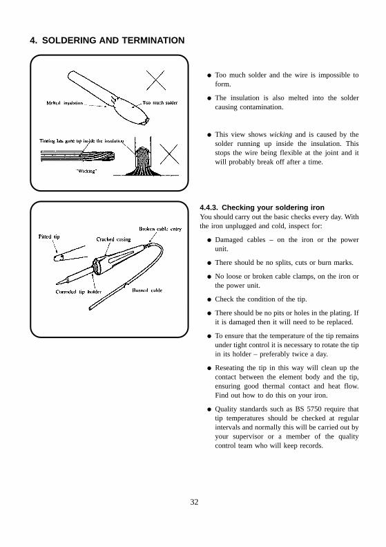
� Too much solder and the wire is impossible toform.
� The insulation is also melted into the soldercausing contamination.
� This view shows wicking and is caused by thesolder running up inside the insulation. Thisstops the wire being flexible at the joint and itwill probably break off after a time.
4.4.3. Checking your soldering ironYou should carry out the basic checks every day. Withthe iron unplugged and cold, inspect for:
� Damaged cables – on the iron or the powerunit.
� There should be no splits, cuts or burn marks.
� No loose or broken cable clamps, on the iron orthe power unit.
� Check the condition of the tip.
� There should be no pits or holes in the plating. Ifit is damaged then it will need to be replaced.
� To ensure that the temperature of the tip remainsunder tight control it is necessary to rotate the tipin its holder – preferably twice a day.
� Reseating the tip in this way will clean up thecontact between the element body and the tip,ensuring good thermal contact and heat flow.Find out how to do this on your iron.
� Quality standards such as BS 5750 require thattip temperatures should be checked at regularintervals and normally this will be carried out byyour supervisor or a member of the qualitycontrol team who will keep records.
32
4. SOLDERING AND TERMINATION
Summary
Soldering
� Remember. Soldering takes much practice.
� Allow the iron to heat up and stabilise beforeyou use it.
� Wet the cleaning sponge.
� Make sure that the surfaces to be solderedare clean and free from grease. The solderwon’t take properly otherwise.
� Use non-corrosive flux-cored solder.
� Make a mechanical joint before soldering.
� Apply the iron tip to heat both parts of thejoint.
� Melt the solder on the joint not the iron.
� The wire outline should still be visible underthe solder.
� Check your iron daily for signs of damage –when the iron is cold!
� Clean plated tips on a wet sponge only.
� Make sure the sponge is kept wet.
� Never file plated tips.
� Always replace the iron in its stand after use.
� Rotate the tip at least once a day if inconstant use.
4.4.4. Safety aspects of soldering
� Molten solder can easily burn flesh and cause serious damage to eyes should there be directcontact.
� The soldering tip will burn skin and clothing.
� Keep the iron in an enclosing holder when not being used.
� Always use the damp sponge to clean the tip – never flick the iron.
� Protective clothing, when instructed, should be worn.
� Find out where the First Aid box is, including eyebaths, which should be available in theworkplace.
� Most irons are 12 V or 24 V powered and are therefore relatively safe from the electric shock pointof view.
� Mains-powered types must be earthed to the line earth and checked frequently for damage likely tocause a shock hazard.
33
4. SOLDERING AND TERMINATION
4.5. Crimped joints
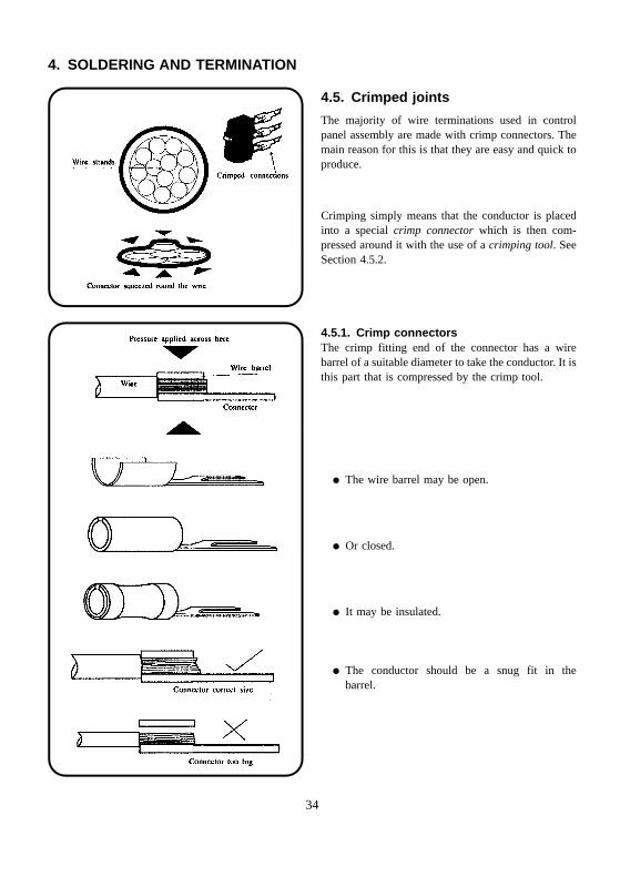
The majority of wire terminations used in controlpanel assembly are made with crimp connectors. Themain reason for this is that they are easy and quick toproduce.
Crimping simply means that the conductor is placedinto a special crimp connector which is then com-pressed around it with the use of a crimping tool. SeeSection 4.5.2.
4.5.1. Crimp connectorsThe crimp fitting end of the connector has a wirebarrel of a suitable diameter to take the conductor. It isthis part that is compressed by the crimp tool.
� The wire barrel may be open.
� Or closed.
� It may be insulated.
� The conductor should be a snug fit in thebarrel.
34

4. SOLDERING AND TERMINATION
The actual connector can have any one of a widevariety of shapes determined by the requirements ofthe job.
� Here are some commonly used single wire crimpconnectors. All are insulated in these examples.
4.5.2. Crimping toolsThe purpose of the crimp tool is to correctly applypressure to the wire barrel to trap the conductor tightlyso that it cannot be pulled out under normal circum-stances. At the same time it must not be so tight as tocause strands or the connector to break.
Crimping tools may be operated in various waysdependent not only on the size of the conductor butsometimes on the total number of crimps that will beneeded. However, they are all similar in operation.
� Hand-operated. Used for light duty work –smaller conductors and small quantities. Theseare described here in detail.
� Power-operated. These can be powered by com-pressed air, electric or hydraulics. Generally theyare bench-mounted but there are hand-heldtypes.
Manufacturer’s instructions should be followedcarefully.
SAFETY!Take care when using power crimpers. Guardsshould be fitted.
35
4. SOLDERING AND TERMINATION
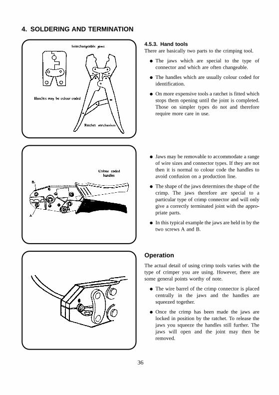
4.5.3. Hand toolsThere are basically two parts to the crimping tool.
� The jaws which are special to the type ofconnector and which are often changeable.
� The handles which are usually colour coded foridentification.
� On more expensive tools a ratchet is fitted whichstops them opening until the joint is completed.Those on simpler types do not and thereforerequire more care in use.
� Jaws may be removable to accommodate a rangeof wire sizes and connector types. If they are notthen it is normal to colour code the handles toavoid confusion on a production line.
� The shape of the jaws determines the shape of thecrimp. The jaws therefore are special to aparticular type of crimp connector and will onlygive a correctly terminated joint with the appro-priate parts.
� In this typical example the jaws are held in by thetwo screws A and B.
Operation
The actual detail of using crimp tools varies with thetype of crimper you are using. However, there aresome general points worthy of note.
� The wire barrel of the crimp connector is placedcentrally in the jaws and the handles aresqueezed together.
� Once the crimp has been made the jaws arelocked in position by the ratchet. To release thejaws you squeeze the handles still further. Thejaws will open and the joint may then beremoved.
36
4. SOLDERING AND TERMINATION
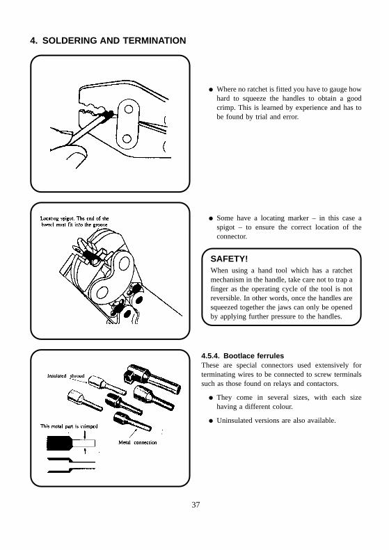
� Where no ratchet is fitted you have to gauge howhard to squeeze the handles to obtain a goodcrimp. This is learned by experience and has tobe found by trial and error.
� Some have a locating marker – in this case aspigot – to ensure the correct location of theconnector.
SAFETY!When using a hand tool which has a ratchetmechanism in the handle, take care not to trap afinger as the operating cycle of the tool is notreversible. In other words, once the handles aresqueezed together the jaws can only be openedby applying further pressure to the handles.
4.5.4. Bootlace ferrulesThese are special connectors used extensively forterminating wires to be connected to screw terminalssuch as those found on relays and contactors.
� They come in several sizes, with each sizehaving a different colour.
� Uninsulated versions are also available.
37
4. SOLDERING AND TERMINATION
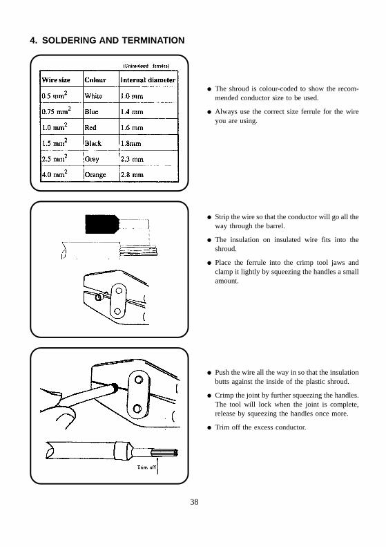
� The shroud is colour-coded to show the recom-mended conductor size to be used.
� Always use the correct size ferrule for the wireyou are using.
� Strip the wire so that the conductor will go all theway through the barrel.
� The insulation on insulated wire fits into theshroud.
� Place the ferrule into the crimp tool jaws andclamp it lightly by squeezing the handles a smallamount.
� Push the wire all the way in so that the insulationbutts against the inside of the plastic shroud.
� Crimp the joint by further squeezing the handles.The tool will lock when the joint is complete,release by squeezing the handles once more.
� Trim off the excess conductor.
38
4. SOLDERING AND TERMINATION
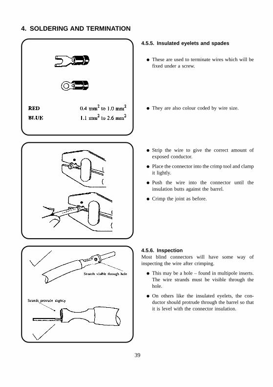
4.5.5. Insulated eyelets and spades
� These are used to terminate wires which will befixed under a screw.
� They are also colour coded by wire size.
� Strip the wire to give the correct amount ofexposed conductor.
� Place the connector into the crimp tool and clampit lightly.
� Push the wire into the connector until theinsulation butts against the barrel.
� Crimp the joint as before.
4.5.6. InspectionMost blind connectors will have some way ofinspecting the wire after crimping.
� This may be a hole – found in multipole inserts.The wire strands must be visible through thehole.
� On others like the insulated eyelets, the con-ductor should protrude through the barrel so thatit is level with the connector insulation.
39
4. SOLDERING AND TERMINATION
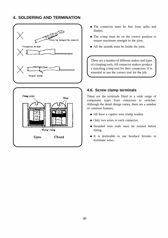
� The connector must be free from splits andflashes.
� The crimp must be on the correct position toensure maximum strength to the joint.
� All the strands must be inside the joint.
There are a number of different makes and typesof crimping tools. All connector makers producea matching crimp tool for their connectors. It isessential to use the correct tool for the job.
4.6. Screw clamp terminals
These are the terminals fitted to a wide range ofcomponent types from contactors to switches.Although the detail design varies, there are a numberof common features.
� All have a captive wire clamp washer.
� Only two wires to each connector.
� Stranded wire ends must be twisted beforefitting.
� It is preferable to use bootlace ferrules toterminate wires.
40
4. SOLDERING AND TERMINATION
4.7. Terminating coaxial cable
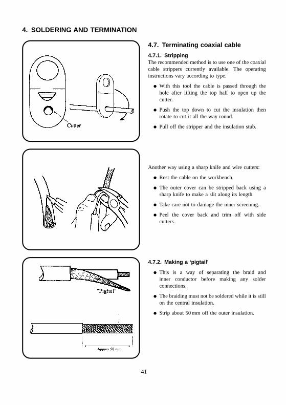
4.7.1. StrippingThe recommended method is to use one of the coaxialcable strippers currently available. The operatinginstructions vary according to type.
� With this tool the cable is passed through thehole after lifting the top half to open up thecutter.
� Push the top down to cut the insulation thenrotate to cut it all the way round.
� Pull off the stripper and the insulation stub.
Another way using a sharp knife and wire cutters:
� Rest the cable on the workbench.
� The outer cover can be stripped back using asharp knife to make a slit along its length.
� Take care not to damage the inner screening.
� Peel the cover back and trim off with sidecutters.
4.7.2. Making a ‘pigtail’
� This is a way of separating the braid andinner conductor before making any solderconnections.
� The braiding must not be soldered while it is stillon the central insulation.
� Strip about 50 mm off the outer insulation.
41
4. SOLDERING AND TERMINATION
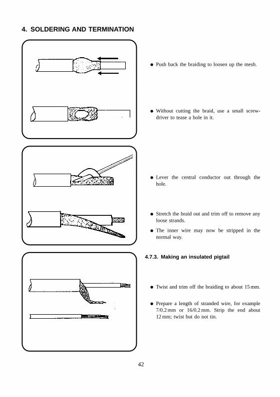
� Push back the braiding to loosen up the mesh.
� Without cutting the braid, use a small screw-driver to tease a hole in it.
� Lever the central conductor out through thehole.
� Stretch the braid out and trim off to remove anyloose strands.
� The inner wire may now be stripped in thenormal way.
4.7.3. Making an insulated pigtail
� Twist and trim off the braiding to about 15 mm.
� Prepare a length of stranded wire, for example7/0.2 mm or 16/0.2 mm. Strip the end about12 mm; twist but do not tin.
42
4. SOLDERING AND TERMINATION
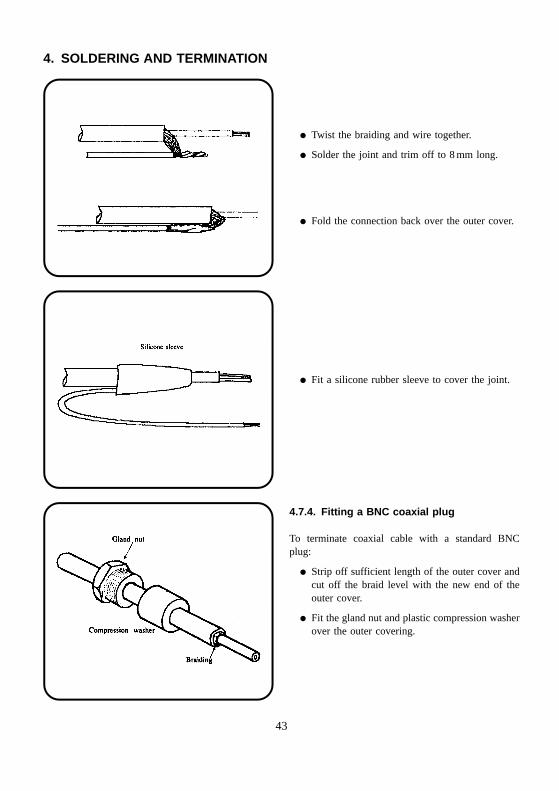
� Twist the braiding and wire together.
� Solder the joint and trim off to 8 mm long.
� Fold the connection back over the outer cover.
� Fit a silicone rubber sleeve to cover the joint.
4.7.4. Fitting a BNC coaxial plug
To terminate coaxial cable with a standard BNCplug:
� Strip off sufficient length of the outer cover andcut off the braid level with the new end of theouter cover.
� Fit the gland nut and plastic compression washerover the outer covering.
43
4. SOLDERING AND TERMINATION
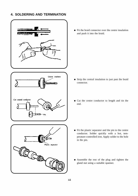
� Fit the braid connector over the centre insulationand push it into the braid.
� Strip the central insulation to just past the braidconnector.
� Cut the centre conductor to length and tin theend.
� Fit the plastic separator and the pin to the centreconductor. Solder quickly with a hot, tem-perature-controlled iron. Apply solder to the holein the pin.
� Assemble the rest of the plug and tighten thegland nut using a suitable spanner.
44
4. SOLDERING AND TERMINATION
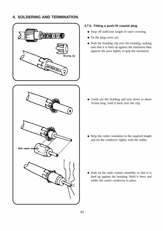
4.7.5. Fitting a push-fit coaxial plug
� Strip off sufficient length of outer covering.
� Fit the plug cover nut.
� Push the braiding clip over the braiding, makingsure that it is hard up against the insulation thensqueeze the jaws lightly to grip the insulation.
� Comb out the braiding and trim down to about10 mm long. Fold it back over the clip.
� Strip the centre insulation to the required lengthand tin the conductor lightly with the solder.
� Push on the male contact assembly so that it ishard up against the braiding. Hold it there andsolder the centre conductor in place.
45
4. SOLDERING AND TERMINATION
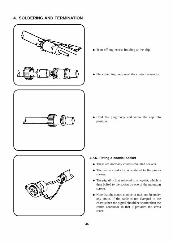
� Trim off any excess braiding at the clip.
� Place the plug body onto the contact assembly.
� Hold the plug body and screw the cap intoposition.
4.7.6. Fitting a coaxial socket
� These are normally chassis-mounted sockets.
� The centre conductor is soldered to the pin asshown.
� The pigtail is first soldered to an eyelet, which isthen bolted to the socket by one of the mountingscrews.
� Note that the centre conductor must not be underany strain. If the cable is not clamped to thechassis then the pigtail should be shorter than thecentre conductor so that it provides the stressrelief.
46
5. CABLE FORMING
5.1. Cableforms
A cableform is where a number of individual wires,which may be of different sizes and types, are boundtogether to form a single cable run. Alternative namesare cable harness or wiring loom.
Cableforms are often made up as a separate item alongwith other components for the equipment in whichthey will be installed and the following information isusually provided:
� Wiring schedule.
� Cableform template.
� Run-out sheet or table.
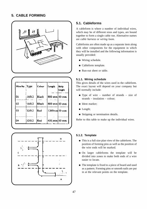
5.1.1. Wiring scheduleThis gives details of the wires used in the cableform.The exact layout will depend on your company butwill normally include:
� Type of wire – number of strands – size ofstrands – insulation – colour;
� Ident marker;
� Length;
� Stripping or termination details.
Refer to this table to make up the individual wires.
5.1.2. Template
� This is a full size plan view of the cableform. Theposition of forming pins as well as the position ofthe wire ends will be marked.
� On larger cableforms the template will bedivided into zones to make both ends of a wireeasier to locate.
� The template is fixed to a piece of board and usedas a pattern. Forming pins or smooth nails are putin at the relevant points on the template.
47
5. CABLE FORMING
� The cableform is made by laying the wiresbetween the connection points and following theshape made by the forming pins which keep thewires together until they are bound into acableform.
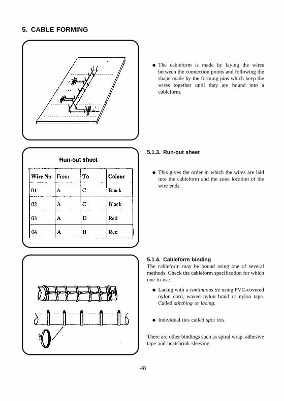
5.1.3. Run-out sheet
� This gives the order in which the wires are laidinto the cableform and the zone location of thewire ends.
5.1.4. Cableform bindingThe cableform may be bound using one of severalmethods. Check the cableform specification for whichone to use.
� Lacing with a continuous tie using PVC-coverednylon cord, waxed nylon braid or nylon tape.Called stitching or lacing.
� Individual ties called spot ties.
There are other bindings such as spiral wrap, adhesivetape and heatshrink sleeving.
48
5. CABLE FORMING
5.2. Continuous lacing
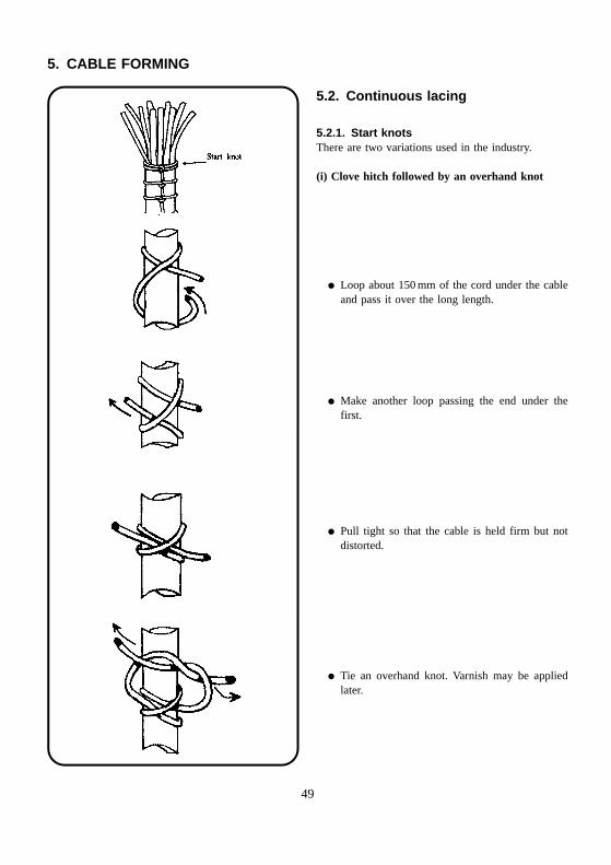
5.2.1. Start knotsThere are two variations used in the industry.
(i) Clove hitch followed by an overhand knot
� Loop about 150 mm of the cord under the cableand pass it over the long length.
� Make another loop passing the end under thefirst.
� Pull tight so that the cable is held firm but notdistorted.
� Tie an overhand knot. Varnish may be appliedlater.
49
5. CABLE FORMING
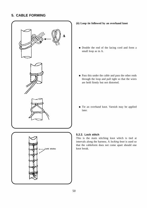
(ii) Loop tie followed by an overhand knot
� Double the end of the lacing cord and form asmall loop as in A.
� Pass this under the cable and pass the other endsthrough the loop and pull tight so that the wiresare held firmly but not distorted.
� Tie an overhand knot. Varnish may be appliedlater.
5.2.2. Lock stitchThis is the main stitching knot which is tied atintervals along the harness. A locking knot is used sothat the cableform does not come apart should oneknot break.
50
5. CABLE FORMING
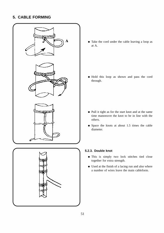
� Take the cord under the cable leaving a loop asat A.
� Hold this loop as shown and pass the cordthrough.
� Pull it tight as for the start knot and at the sametime manoeuvre the knot to be in line with theothers.
� Space the knots at about 1.5 times the cablediameter.
5.2.3. Double knot
� This is simply two lock stitches tied closetogether for extra strength.
� Used at the finish of a lacing run and also wherea number of wires leave the main cableform.
51
5. CABLE FORMING
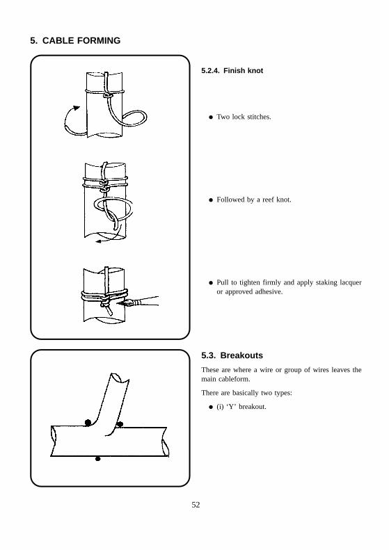
5.2.4. Finish knot
� Two lock stitches.
� Followed by a reef knot.
� Pull to tighten firmly and apply staking lacqueror approved adhesive.
5.3. Breakouts
These are where a wire or group of wires leaves themain cableform.
There are basically two types:
� (i) ‘Y’ breakout.
52
5. CABLE FORMING
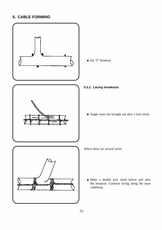
� (ii) ‘T’ breakout.
5.3.1. Lacing breakouts
� Single wires are brought out after a lock stitch.
Where there are several wires:
� Make a double lock stitch before and afterthe breakout. Continue lacing along the maincableform.
53
5. CABLE FORMING
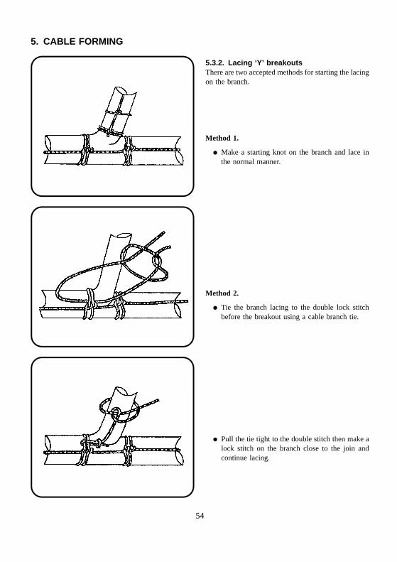
5.3.2. Lacing ‘Y’ breakoutsThere are two accepted methods for starting the lacingon the branch.
Method 1.
� Make a starting knot on the branch and lace inthe normal manner.
Method 2.
� Tie the branch lacing to the double lock stitchbefore the breakout using a cable branch tie.
� Pull the tie tight to the double stitch then make alock stitch on the branch close to the join andcontinue lacing.
54
5. CABLE FORMING
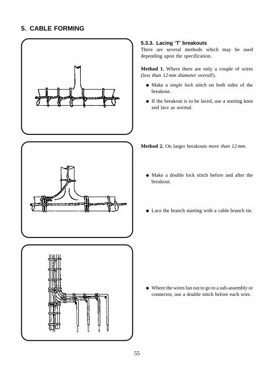
5.3.3. Lacing ‘T’ breakoutsThere are several methods which may be useddepending upon the specification.
Method 1. Where there are only a couple of wires(less than 12 mm diameter overall).
� Make a single lock stitch on both sides of thebreakout.
� If the breakout is to be laced, use a starting knotand lace as normal.
Method 2. On larger breakouts more than 12 mm.
� Make a double lock stitch before and after thebreakout.
� Lace the branch starting with a cable branch tie.
� Where the wires fan out to go to a sub-assembly orconnector, use a double stitch before each wire.
55

5. CABLE FORMING
5.4. Spot ties
5.4.1. Lacing cord
� Make these as you do a starting knot with a clovehitch and a reef knot. The knot can be sealedusing adhesive or varnish.
5.4.2. Cable ties
� These come in several very similar shapes. Allare like a belt and buckle. One side of the belt isserrated. This side goes toward the cable. Theend is passed through the eye in the buckle andpulled tight.
There are tools available which allow the correcttension to be obtained every time. Trim off thewaste.
5.5. Laying the wires
Whichever method of binding is used, here are somerules to follow:
� Prepare the wires according to the wiring sched-ule and lay them on to the template in the orderfound in the run-out sheet.
� Avoid kinks in the wires.
� Lay the wires as straight and parallel aspossible.
56
5. CABLE FORMING
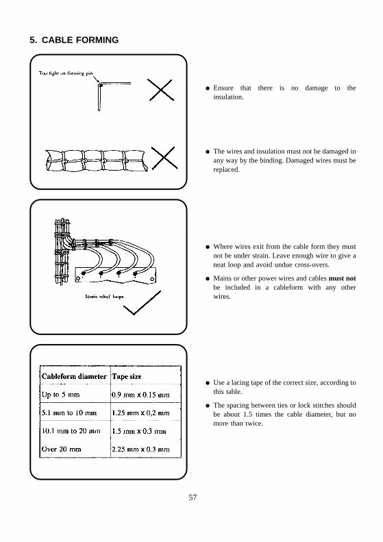
� Ensure that there is no damage to theinsulation.
� The wires and insulation must not be damaged inany way by the binding. Damaged wires must bereplaced.
� Where wires exit from the cable form they mustnot be under strain. Leave enough wire to give aneat loop and avoid undue cross-overs.
� Mains or other power wires and cables must notbe included in a cableform with any otherwires.
� Use a lacing tape of the correct size, according tothis table.
� The spacing between ties or lock stitches shouldbe about 1.5 times the cable diameter, but nomore than twice.
57
5. CABLE FORMING
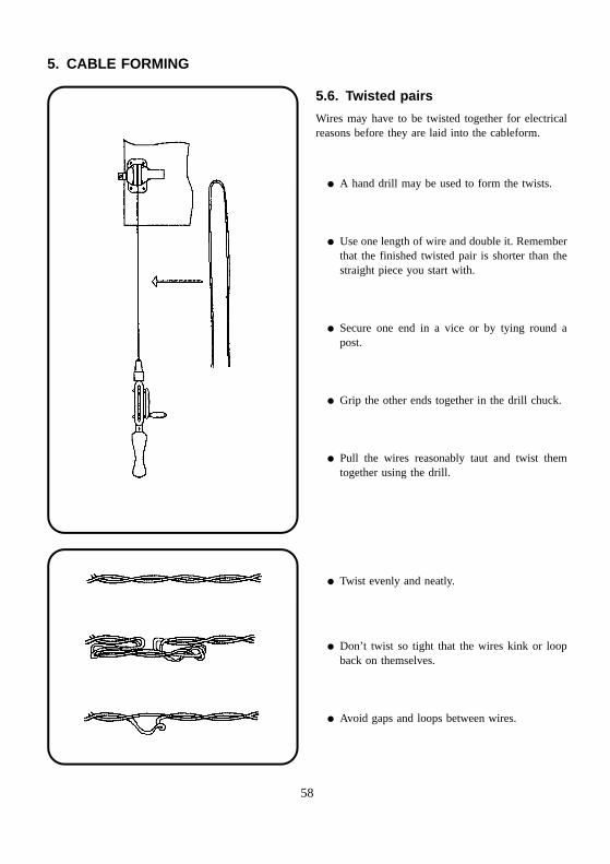
5.6. Twisted pairs
Wires may have to be twisted together for electricalreasons before they are laid into the cableform.
� A hand drill may be used to form the twists.
� Use one length of wire and double it. Rememberthat the finished twisted pair is shorter than thestraight piece you start with.
� Secure one end in a vice or by tying round apost.
� Grip the other ends together in the drill chuck.
� Pull the wires reasonably taut and twist themtogether using the drill.
� Twist evenly and neatly.
� Don’t twist so tight that the wires kink or loopback on themselves.
� Avoid gaps and loops between wires.
58
5. CABLE FORMING
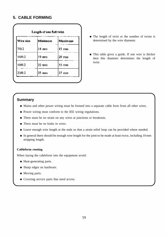
� The length of twist or the number of twists isdetermined by the wire diameter.
� This table gives a guide. If one wire is thickerthen this diameter determines the length oftwist.
Summary
� Mains and other power wiring must be formed into a separate cable form from all other wires.
� Power wiring must conform to the IEE wiring regulations.
� There must be no strain on any wires at junctions or breakouts.
� There must be no kinks in wires.
� Leave enough wire length at the ends so that a strain relief loop can be provided where needed.
� In general there should be enough wire length for the joint to be made at least twice, including 10 mmstripping length.
Cableform routing
When laying the cableform into the equipment avoid:
� Heat-generating parts.
� Sharp edges on hardware.
� Moving parts.
� Covering service parts that need access.
59
5. CABLE FORMING
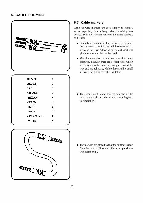
5.7. Cable markers
Cable or wire markers are used simply to identifywires, especially in multiway cables or wiring har-nesses. Both ends are marked with the same numbersto be used.
� Often these numbers will be the same as those onthe connector to which they will be connected. Inany case the wiring drawing or run-out sheet willgive the wire numbers to be used.
� Most have numbers printed on as well as beingcoloured, although there are several types whichare coloured only. Some are wrapped round thewire and are adhesive, while others are like smallsleeves which slip over the insulation.
� The colours used to represent the numbers are thesame as the resistor code so there is nothing newto remember!
� The markers are placed so that the number is readfrom the joint as illustrated. This example showswire number 27.
60
5. CABLE FORMING
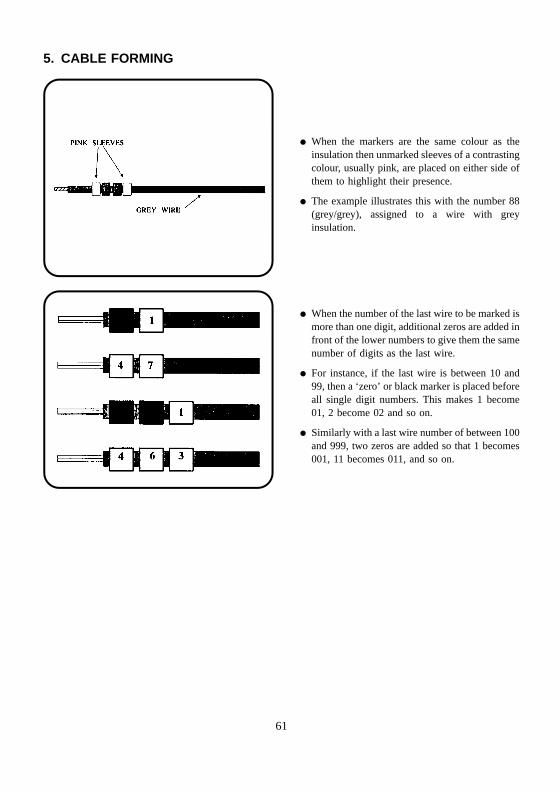
� When the markers are the same colour as theinsulation then unmarked sleeves of a contrastingcolour, usually pink, are placed on either side ofthem to highlight their presence.
� The example illustrates this with the number 88(grey/grey), assigned to a wire with greyinsulation.
� When the number of the last wire to be marked ismore than one digit, additional zeros are added infront of the lower numbers to give them the samenumber of digits as the last wire.
� For instance, if the last wire is between 10 and99, then a ‘zero’ or black marker is placed beforeall single digit numbers. This makes 1 become01, 2 become 02 and so on.
� Similarly with a last wire number of between 100and 999, two zeros are added so that 1 becomes001, 11 becomes 011, and so on.
61
Stud
Lock nut
Star washers Earth connector
6. CONNECTIONS AND ROUTING
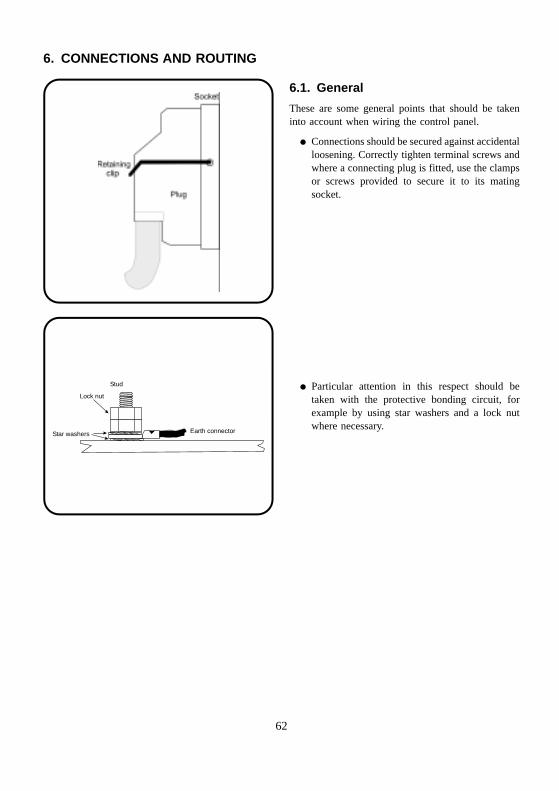
6.1. General
These are some general points that should be takeninto account when wiring the control panel.
� Connections should be secured against accidentalloosening. Correctly tighten terminal screws andwhere a connecting plug is fitted, use the clampsor screws provided to secure it to its matingsocket.
� Particular attention in this respect should betaken with the protective bonding circuit, forexample by using star washers and a lock nutwhere necessary.
62
1 2 3
11 2 3
Use nuts and star washers
Fixing screw
Solder tags
6. CONNECTIONS AND ROUTING
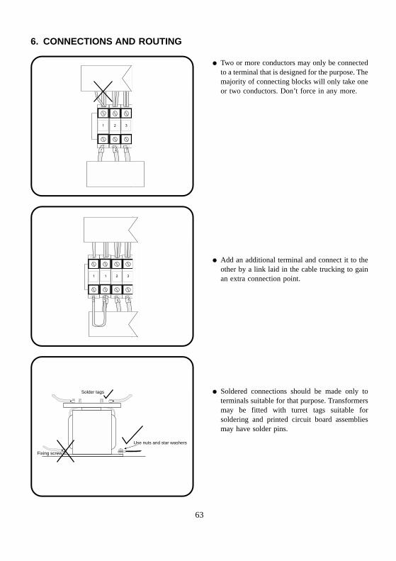
� Two or more conductors may only be connectedto a terminal that is designed for the purpose. Themajority of connecting blocks will only take oneor two conductors. Don’t force in any more.
� Add an additional terminal and connect it to theother by a link laid in the cable trucking to gainan extra connection point.
� Soldered connections should be made only toterminals suitable for that purpose. Transformersmay be fitted with turret tags suitable forsoldering and printed circuit board assembliesmay have solder pins.
63
Bootlace ferrule
Sleeving
Pigtail
6. CONNECTIONS AND ROUTING
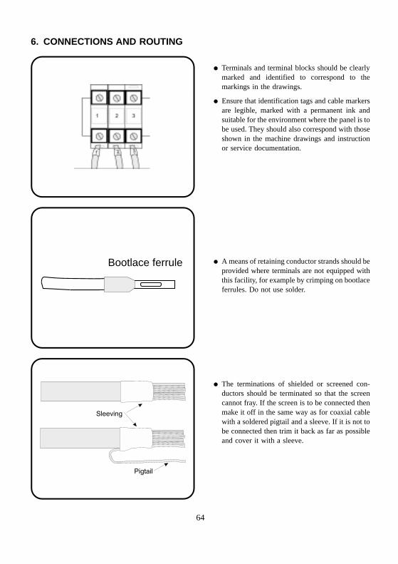
� Terminals and terminal blocks should be clearlymarked and identified to correspond to themarkings in the drawings.
� Ensure that identification tags and cable markersare legible, marked with a permanent ink andsuitable for the environment where the panel is tobe used. They should also correspond with thoseshown in the machine drawings and instructionor service documentation.
� A means of retaining conductor strands should beprovided where terminals are not equipped withthis facility, for example by crimping on bootlaceferrules. Do not use solder.
� The terminations of shielded or screened con-ductors should be terminated so that the screencannot fray. If the screen is to be connected thenmake it off in the same way as for coaxial cablewith a soldered pigtail and a sleeve. If it is not tobe connected then trim it back as far as possibleand cover it with a sleeve.
64
Control panel
Electrical machine
Flexible conduit
6. CONNECTIONS AND ROUTING
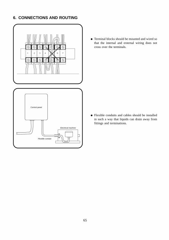
� Terminal blocks should be mounted and wired sothat the internal and external wiring does notcross over the terminals.
� Flexible conduits and cables should be installedin such a way that liquids can drain away fromfittings and terminations.
65
Removable
module
Extra length
Clamp cable securely
PE L1 L2 L3 N
6. CONNECTIONS AND ROUTING
6.2. Conductor and cable runs
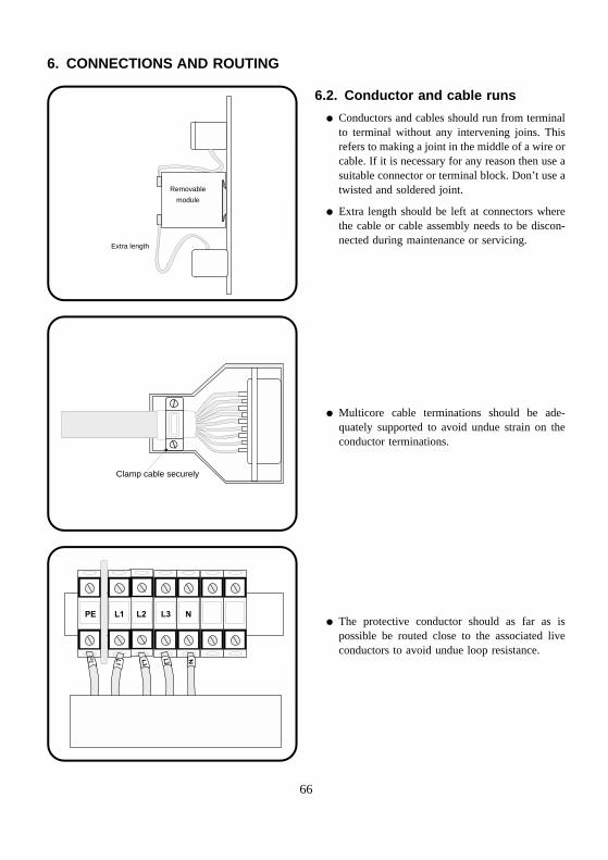
� Conductors and cables should run from terminalto terminal without any intervening joins. Thisrefers to making a joint in the middle of a wire orcable. If it is necessary for any reason then use asuitable connector or terminal block. Don’t use atwisted and soldered joint.
� Extra length should be left at connectors wherethe cable or cable assembly needs to be discon-nected during maintenance or servicing.
� Multicore cable terminations should be ade-quately supported to avoid undue strain on theconductor terminations.
� The protective conductor should as far as ispossible be routed close to the associated liveconductors to avoid undue loop resistance.
66
PLC
Powercontactor
AC electric motor
Low power
sensors
Electromagnetic field
PLC
AC electric motorElectromagnetic field
trapped in conduit
Separate conduits
Low powersensors
Powercontactor
6. CONNECTIONS AND ROUTING
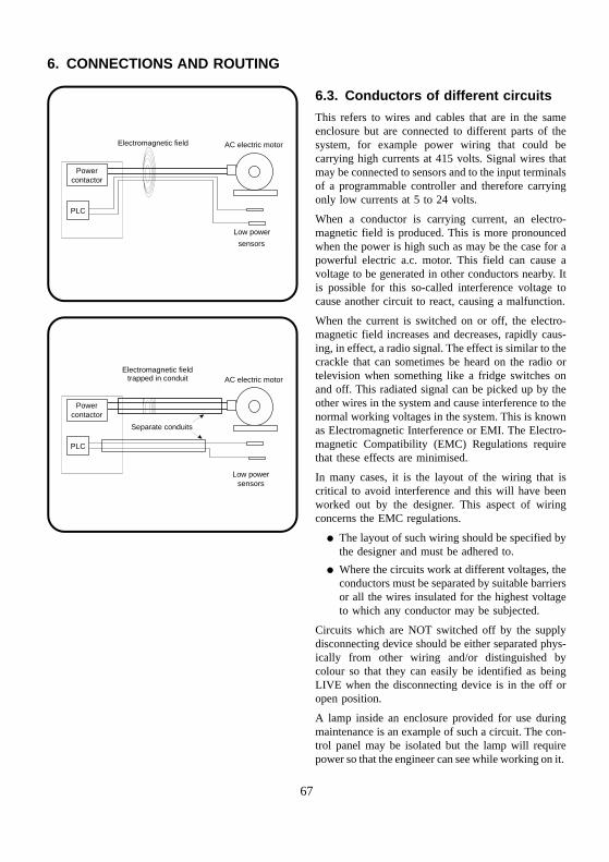
6.3. Conductors of different circuits
This refers to wires and cables that are in the sameenclosure but are connected to different parts of thesystem, for example power wiring that could becarrying high currents at 415 volts. Signal wires thatmay be connected to sensors and to the input terminalsof a programmable controller and therefore carryingonly low currents at 5 to 24 volts.
When a conductor is carrying current, an electro-magnetic field is produced. This is more pronouncedwhen the power is high such as may be the case for apowerful electric a.c. motor. This field can cause avoltage to be generated in other conductors nearby. Itis possible for this so-called interference voltage tocause another circuit to react, causing a malfunction.
When the current is switched on or off, the electro-magnetic field increases and decreases, rapidly caus-ing, in effect, a radio signal. The effect is similar to thecrackle that can sometimes be heard on the radio ortelevision when something like a fridge switches onand off. This radiated signal can be picked up by theother wires in the system and cause interference to thenormal working voltages in the system. This is knownas Electromagnetic Interference or EMI. The Electro-magnetic Compatibility (EMC) Regulations requirethat these effects are minimised.
In many cases, it is the layout of the wiring that iscritical to avoid interference and this will have beenworked out by the designer. This aspect of wiringconcerns the EMC regulations.
� The layout of such wiring should be specified bythe designer and must be adhered to.
� Where the circuits work at different voltages, theconductors must be separated by suitable barriersor all the wires insulated for the highest voltageto which any conductor may be subjected.
Circuits which are NOT switched off by the supplydisconnecting device should be either separated phys-ically from other wiring and/or distinguished bycolour so that they can easily be identified as beingLIVE when the disconnecting device is in the off oropen position.
A lamp inside an enclosure provided for use duringmaintenance is an example of such a circuit. The con-trol panel may be isolated but the lamp will requirepower so that the engineer can see while working on it.
67
7. HARDWARE
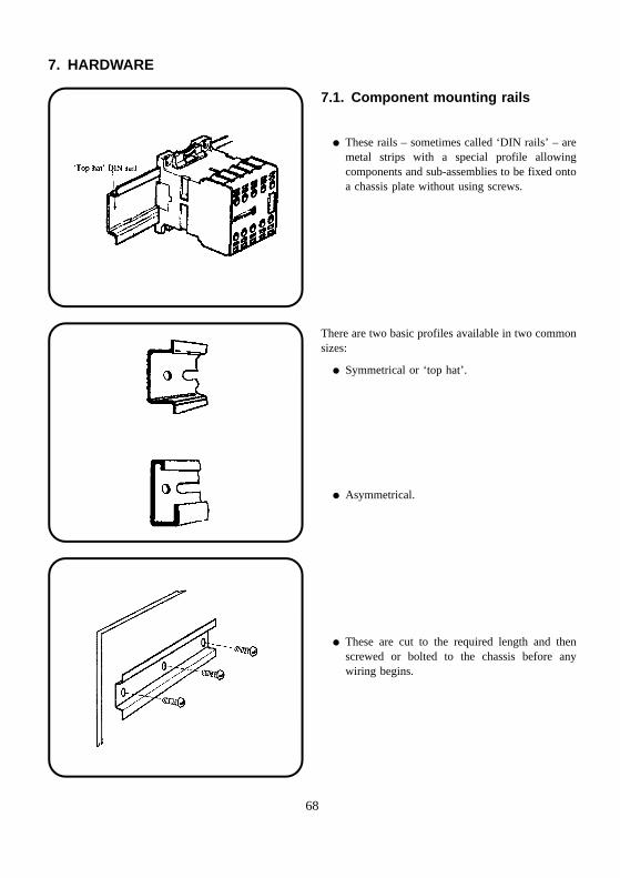
7.1. Component mounting rails
� These rails – sometimes called ‘DIN rails’ – aremetal strips with a special profile allowingcomponents and sub-assemblies to be fixed ontoa chassis plate without using screws.
There are two basic profiles available in two commonsizes:
� Symmetrical or ‘top hat’.
� Asymmetrical.
� These are cut to the required length and thenscrewed or bolted to the chassis before anywiring begins.
68
7. HARDWARE
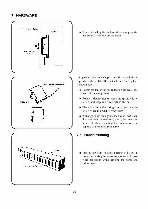
� To avoid fouling the underneath of components,use screws with low profile heads.
Components are then clipped on. The actual detaildepends on the profile. The method used for ‘top hat’is shown here.
� Locate the top of the rail in the top groove at theback of the component.
� Rotate it downwards to cause the spring clip toretract and snap into place behind the rail.
� There is a slot in the spring clip so that it can beretracted using a small screwdriver.
� Although this is mainly intended to be used whenthe component is removed, it may be necessaryto use it when mounting the component if itappears to need too much force.
7.2. Plastic trunking
� This is one form of cable ducting and used tocarry the wiring between components. It pro-vides protection while keeping the wires andcables neat.
69
7. HARDWARE
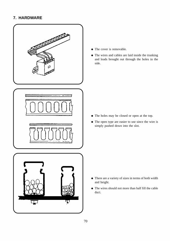
� The cover is removable.
� The wires and cables are laid inside the trunkingand leads brought out through the holes in theside.
� The holes may be closed or open at the top.
� The open type are easier to use since the wire issimply pushed down into the slot.
� There are a variety of sizes in terms of both widthand height.
� The wires should not more than half fill the cableduct.
70
7. HARDWARE
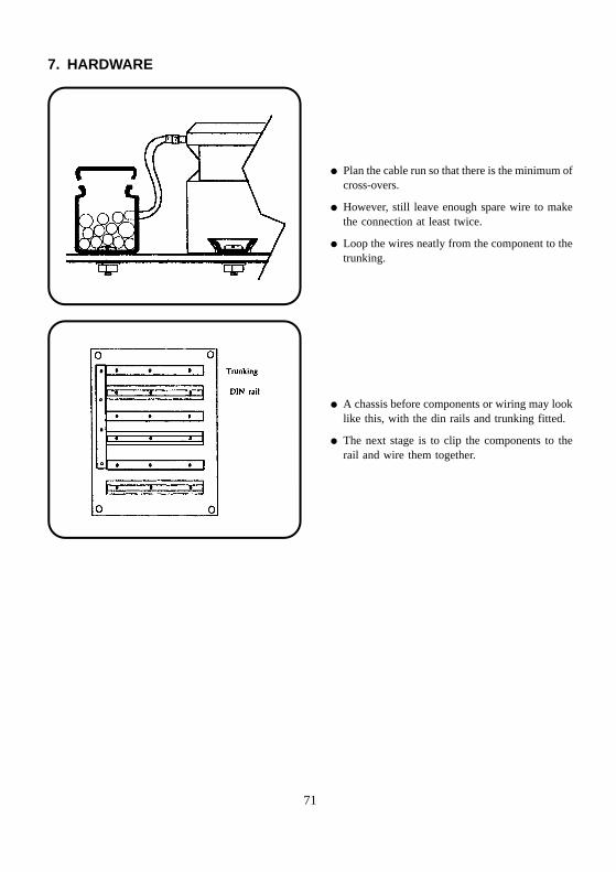
� Plan the cable run so that there is the minimum ofcross-overs.
� However, still leave enough spare wire to makethe connection at least twice.
� Loop the wires neatly from the component to thetrunking.
� A chassis before components or wiring may looklike this, with the din rails and trunking fitted.
� The next stage is to clip the components to therail and wire them together.
71
7. HARDWARE
7.3. Connector blocks
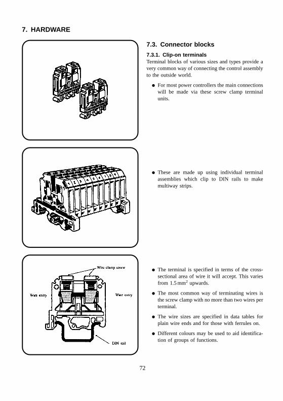
7.3.1. Clip-on terminalsTerminal blocks of various sizes and types provide avery common way of connecting the control assemblyto the outside world.
� For most power controllers the main connectionswill be made via these screw clamp terminalunits.
� These are made up using individual terminalassemblies which clip to DIN rails to makemultiway strips.
� The terminal is specified in terms of the cross-sectional area of wire it will accept. This variesfrom 1.5 mm2 upwards.
� The most common way of terminating wires isthe screw clamp with no more than two wires perterminal.
� The wire sizes are specified in data tables forplain wire ends and for those with ferrules on.
� Different colours may be used to aid identifica-tion of groups of functions.
72
7. HARDWARE
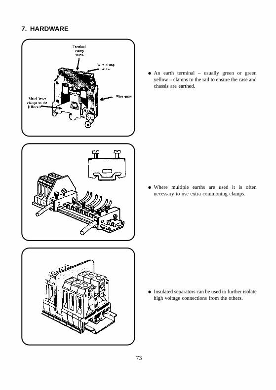
� An earth terminal – usually green or greenyellow – clamps to the rail to ensure the case andchassis are earthed.
� Where multiple earths are used it is oftennecessary to use extra commoning clamps.
� Insulated separators can be used to further isolatehigh voltage connections from the others.
73
7. HARDWARE
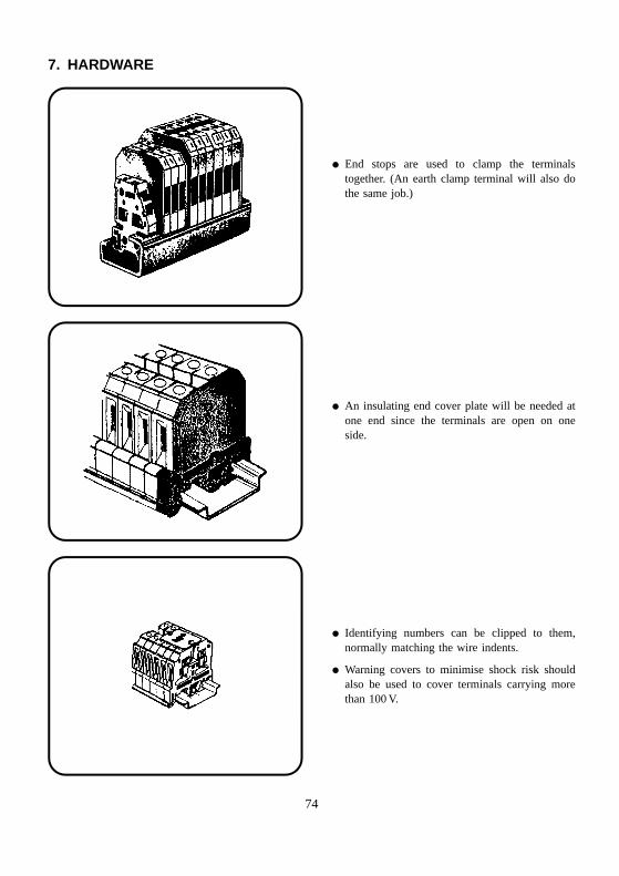
� End stops are used to clamp the terminalstogether. (An earth clamp terminal will also dothe same job.)
� An insulating end cover plate will be needed atone end since the terminals are open on oneside.
� Identifying numbers can be clipped to them,normally matching the wire indents.
� Warning covers to minimise shock risk shouldalso be used to cover terminals carrying morethan 100 V.
74
7. HARDWARE
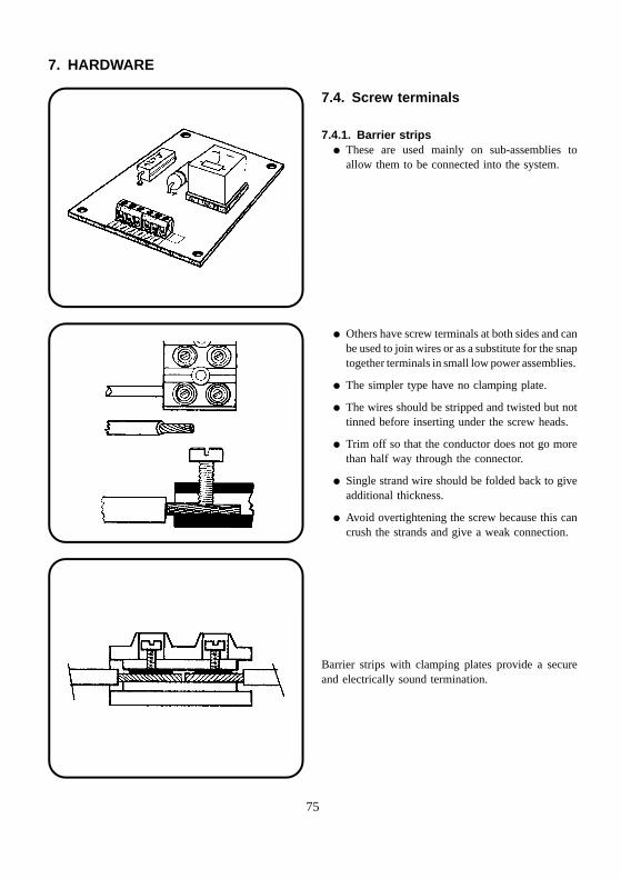
7.4. Screw terminals
7.4.1. Barrier strips� These are used mainly on sub-assemblies to
allow them to be connected into the system.
� Others have screw terminals at both sides and canbe used to join wires or as a substitute for the snaptogether terminals in small low power assemblies.
� The simpler type have no clamping plate.
� The wires should be stripped and twisted but nottinned before inserting under the screw heads.
� Trim off so that the conductor does not go morethan half way through the connector.
� Single strand wire should be folded back to giveadditional thickness.
� Avoid overtightening the screw because this cancrush the strands and give a weak connection.
Barrier strips with clamping plates provide a secureand electrically sound termination.
75
Armature
Return spring
Iron core
Coil
Contacts
NC NO
Common
Moving contact
Armature
Return spring
Iron core
Coil
Contacts
NC NO
Common
Moving contact
Fixed contactsMoving contacts
Operating coil
Moving armature
Fixed armature
Return spring
8. COMPONENTS (ACTIVE)
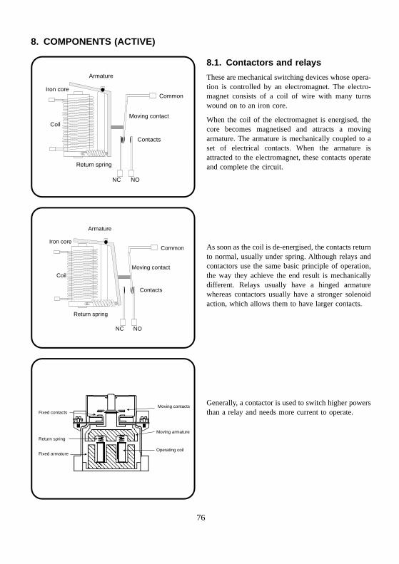
8.1. Contactors and relays
These are mechanical switching devices whose opera-tion is controlled by an electromagnet. The electro-magnet consists of a coil of wire with many turnswound on to an iron core.
When the coil of the electromagnet is energised, thecore becomes magnetised and attracts a movingarmature. The armature is mechanically coupled to aset of electrical contacts. When the armature isattracted to the electromagnet, these contacts operateand complete the circuit.
As soon as the coil is de-energised, the contacts returnto normal, usually under spring. Although relays andcontactors use the same basic principle of operation,the way they achieve the end result is mechanicallydifferent. Relays usually have a hinged armaturewhereas contactors usually have a stronger solenoidaction, which allows them to have larger contacts.
Generally, a contactor is used to switch higher powersthan a relay and needs more current to operate.
76
Fixed contactsMoving contacts
Operating coil
Moving armature
Fixed armature
Return spring
8. COMPONENTS (ACTIVE)
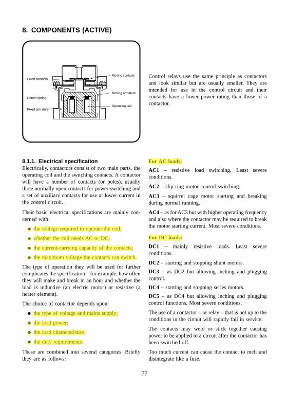
Control relays use the same principle as contactorsand look similar but are usually smaller. They areintended for use in the control circuit and theircontacts have a lower power rating than those of acontactor.
8.1.1. Electrical specificationElectrically, contactors consist of two main parts, theoperating coil and the switching contacts. A contactorwill have a number of contacts (or poles), usuallythree normally open contacts for power switching anda set of auxiliary contacts for use at lower current inthe control circuit.
Their basic electrical specifications are mainly con-cerned with:
� the voltage required to operate the coil;
� whether the coil needs AC or DC;
� the current-carrying capacity of the contacts;
� the maximum voltage the contacts can switch.
The type of operation they will be used for furthercomplicates the specification – for example, how oftenthey will make and break in an hour and whether theload is inductive (an electric motor) or resistive (aheater element).
The choice of contactor depends upon:
� the type of voltage and mains supply;
� the load power;
� the load characteristics;
� the duty requirements.
These are combined into several categories. Brieflythey are as follows:
For AC loads:
AC1 – resistive load switching. Least severeconditions.
AC2 – slip ring motor control switching.
AC3 – squirrel cage motor starting and breakingduring normal running.
AC4 – as for AC3 but with higher operating frequencyand also where the contactor may be required to breakthe motor starting current. Most severe conditions.
For DC loads:
DC1 – mainly resistive loads. Least severeconditions.
DC2 – starting and stopping shunt motors.
DC3 – as DC2 but allowing inching and pluggingcontrol.
DC4 – starting and stopping series motors.
DC5 – as DC4 but allowing inching and pluggingcontrol functions. Most severe conditions.
The use of a contactor – or relay – that is not up to theconditions in the circuit will rapidly fail in service.
The contacts may weld or stick together causingpower to be applied to a circuit after the contactor hasbeen switched off.
Too much current can cause the contact to melt anddisintegrate like a fuse.
77
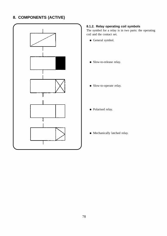
8. COMPONENTS (ACTIVE)
78
8.1.2. Relay operating coil symbolsThe symbol for a relay is in two parts: the operatingcoil and the contact set.
� General symbol.
� Slow-to-release relay.
� Slow-to-operate relay.
� Polarised relay.
� Mechanically latched relay.
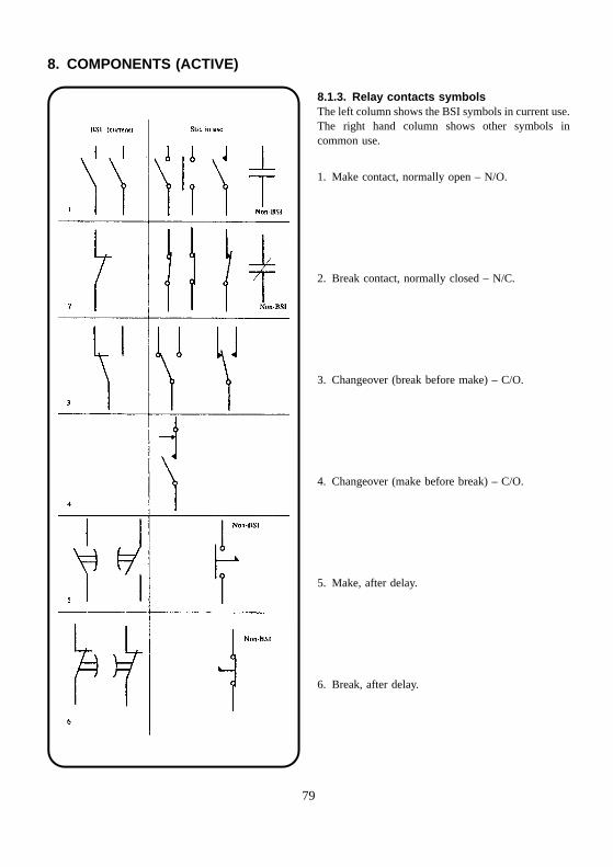
8. COMPONENTS (ACTIVE)
8.1.3. Relay contacts symbolsThe left column shows the BSI symbols in current use.The right hand column shows other symbols incommon use.
1. Make contact, normally open – N/O.
2. Break contact, normally closed – N/C.
3. Changeover (break before make) – C/O.
4. Changeover (make before break) – C/O.
5. Make, after delay.
6. Break, after delay.
79
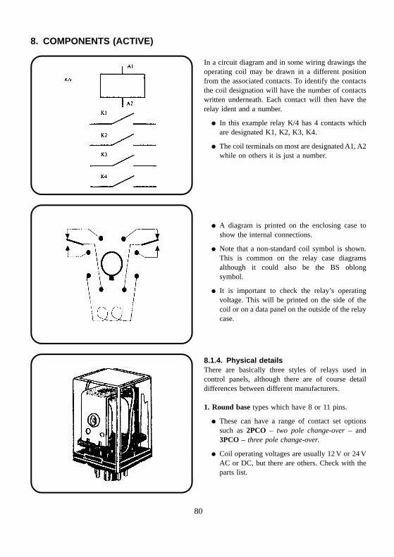
8. COMPONENTS (ACTIVE)
In a circuit diagram and in some wiring drawings theoperating coil may be drawn in a different positionfrom the associated contacts. To identify the contactsthe coil designation will have the number of contactswritten underneath. Each contact will then have therelay ident and a number.
� In this example relay K/4 has 4 contacts whichare designated K1, K2, K3, K4.
� The coil terminals on most are designated A1, A2while on others it is just a number.
� A diagram is printed on the enclosing case toshow the internal connections.
� Note that a non-standard coil symbol is shown.This is common on the relay case diagramsalthough it could also be the BS oblongsymbol.
� It is important to check the relay’s operatingvoltage. This will be printed on the side of thecoil or on a data panel on the outside of the relaycase.
8.1.4. Physical detailsThere are basically three styles of relays used incontrol panels, although there are of course detaildifferences between different manufacturers.
1. Round base types which have 8 or 11 pins.
� These can have a range of contact set optionssuch as 2PCO – two pole change-over – and3PCO – three pole change-over.
� Coil operating voltages are usually 12 V or 24 VAC or DC, but there are others. Check with theparts list.
80
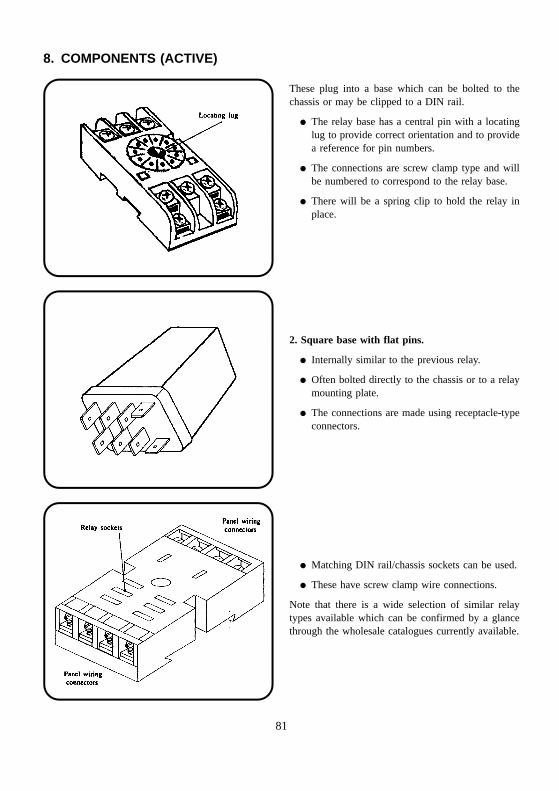
8. COMPONENTS (ACTIVE)
These plug into a base which can be bolted to thechassis or may be clipped to a DIN rail.
� The relay base has a central pin with a locatinglug to provide correct orientation and to providea reference for pin numbers.
� The connections are screw clamp type and willbe numbered to correspond to the relay base.
� There will be a spring clip to hold the relay inplace.
2. Square base with flat pins.
� Internally similar to the previous relay.
� Often bolted directly to the chassis or to a relaymounting plate.
� The connections are made using receptacle-typeconnectors.
� Matching DIN rail/chassis sockets can be used.
� These have screw clamp wire connections.
Note that there is a wide selection of similar relaytypes available which can be confirmed by a glancethrough the wholesale catalogues currently available.
81
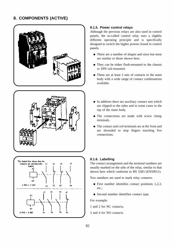
8. COMPONENTS (ACTIVE)
8.1.5. Power control relaysAlthough the previous relays are also used in controlpanels, the so-called control relay uses a slightlydifferent operating principle and is specificallydesigned to switch the higher powers found in controlpanels.
� There are a number of shapes and sizes but mostare similar to those shown here.
� They can be either flush-mounted to the chassisor DIN rail-mounted.
� There are at least 3 sets of contacts in the mainbody with a wide range of contact combinationsavailable.
� In addition there are auxiliary contact sets whichare clipped to the sides and in some cases to thetop of the main body.
� The connections are made with screw clampterminals.
� The contact and coil terminals are at the front andare shrouded to stop fingers touching liveconnections.
8.1.6. LabellingThe contact arrangement and the terminal numbers areusually marked on the side of the relay, similar to thatshown here which conforms to BS 5583 (EN50011).
Two numbers are used to mark relay contacts:
� First number identifies contact positions 1,2,3,etc.;
� Second number identifies contact type.
For example:
1 and 2 for NC contacts;
3 and 4 for NO contacts.
82
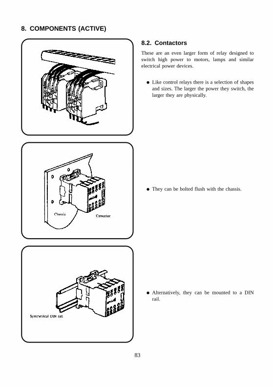
8. COMPONENTS (ACTIVE)
8.2. Contactors
These are an even larger form of relay designed toswitch high power to motors, lamps and similarelectrical power devices.
� Like control relays there is a selection of shapesand sizes. The larger the power they switch, thelarger they are physically.
� They can be bolted flush with the chassis.
� Alternatively, they can be mounted to a DINrail.
83
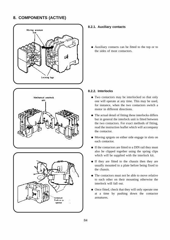
8. COMPONENTS (ACTIVE)
8.2.1. Auxiliary contacts
� Auxiliary contacts can be fitted to the top or tothe sides of most contactors.
8.2.2. Interlocks
� Two contactors may be interlocked so that onlyone will operate at any time. This may be used,for instance, when the two contactors switch amotor in different directions.
� The actual detail of fitting these interlocks differsbut in general the interlock unit is fitted betweenthe two contactors. For exact methods of fitting,read the instruction leaflet which will accompanythe contactor.
� Moving spigots on either side engage in slots oneach contactor.
� If the contactors are fitted to a DIN rail they mustalso be clipped together using the spring clipswhich will be supplied with the interlock kit.
� If they are fitted to the chassis then they areusually mounted to a plate before being fixed tothe chassis.
� The contactors must not be able to move relativeto each other on their mounting otherwise theinterlock will fall out.
� Once fitted, check that they will only operate oneat a time by pushing down the contactorarmatures.
84
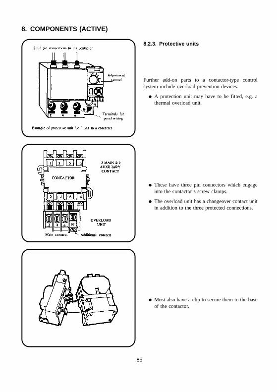
8. COMPONENTS (ACTIVE)
8.2.3. Protective units
Further add-on parts to a contactor-type controlsystem include overload prevention devices.
� A protection unit may have to be fitted, e.g. athermal overload unit.
� These have three pin connectors which engageinto the contactor’s screw clamps.
� The overload unit has a changeover contact unitin addition to the three protected connections.
� Most also have a clip to secure them to the baseof the contactor.
85
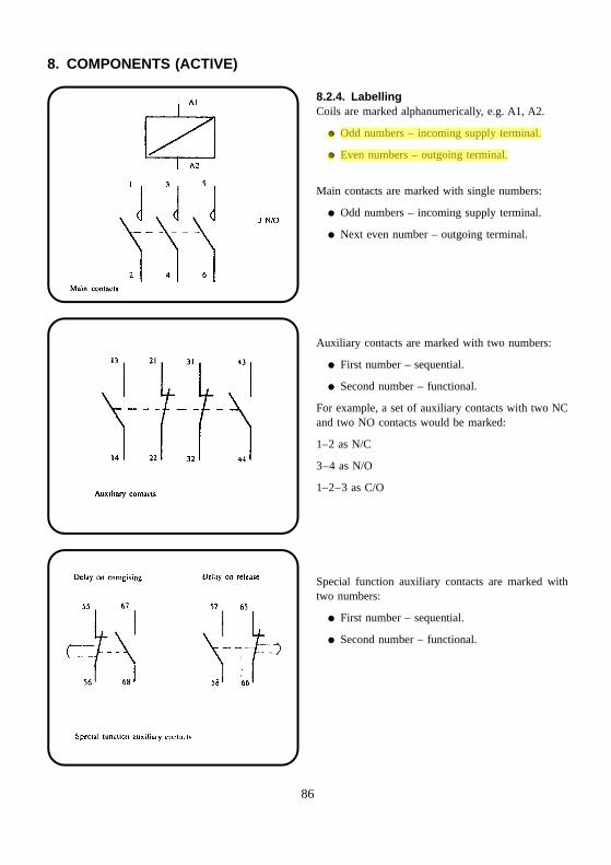
8. COMPONENTS (ACTIVE)
8.2.4. LabellingCoils are marked alphanumerically, e.g. A1, A2.
� Odd numbers – incoming supply terminal.
� Even numbers – outgoing terminal.
Main contacts are marked with single numbers:
� Odd numbers – incoming supply terminal.
� Next even number – outgoing terminal.
Auxiliary contacts are marked with two numbers:
� First number – sequential.
� Second number – functional.
For example, a set of auxiliary contacts with two NCand two NO contacts would be marked:
1–2 as N/C
3–4 as N/O
1–2–3 as C/O
Special function auxiliary contacts are marked withtwo numbers:
� First number – sequential.
� Second number – functional.
86
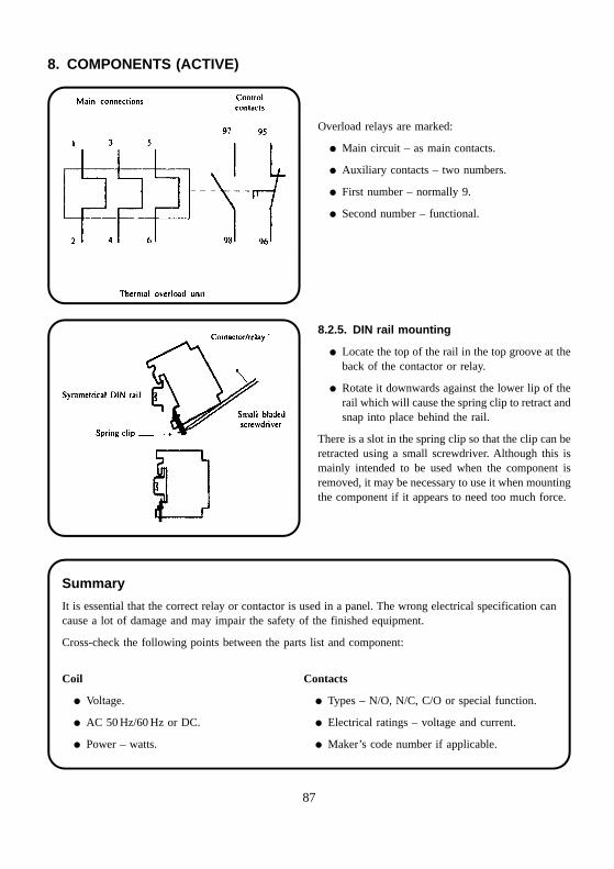
8. COMPONENTS (ACTIVE)
Overload relays are marked:
� Main circuit – as main contacts.
� Auxiliary contacts – two numbers.
� First number – normally 9.
� Second number – functional.
8.2.5. DIN rail mounting
� Locate the top of the rail in the top groove at theback of the contactor or relay.
� Rotate it downwards against the lower lip of therail which will cause the spring clip to retract andsnap into place behind the rail.
There is a slot in the spring clip so that the clip can beretracted using a small screwdriver. Although this ismainly intended to be used when the component isremoved, it may be necessary to use it when mountingthe component if it appears to need too much force.
Summary
It is essential that the correct relay or contactor is used in a panel. The wrong electrical specification cancause a lot of damage and may impair the safety of the finished equipment.
Cross-check the following points between the parts list and component:
Coil Contacts
� Voltage. � Types – N/O, N/C, C/O or special function.
� AC 50 Hz/60 Hz or DC. � Electrical ratings – voltage and current.
� Power – watts. � Maker’s code number if applicable.
87
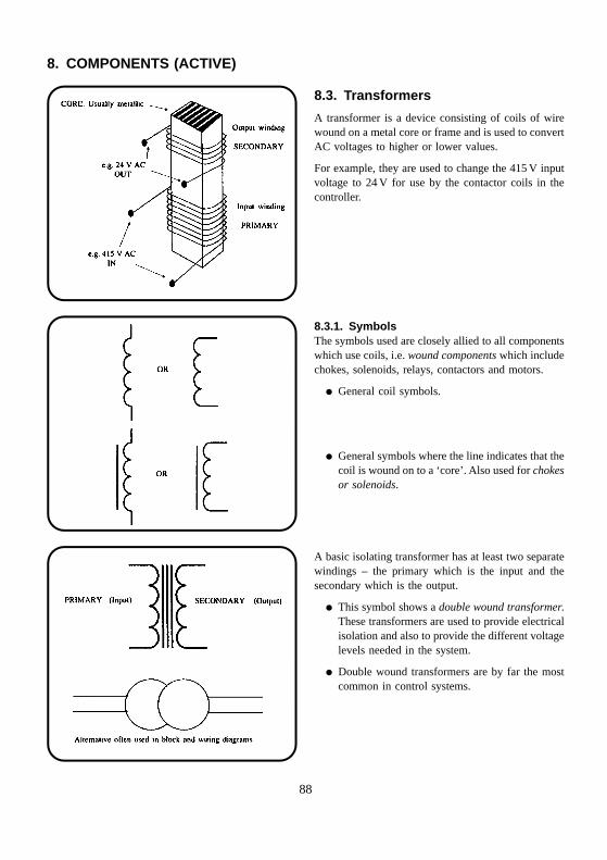
8. COMPONENTS (ACTIVE)
8.3. Transformers
A transformer is a device consisting of coils of wirewound on a metal core or frame and is used to convertAC voltages to higher or lower values.
For example, they are used to change the 415 V inputvoltage to 24 V for use by the contactor coils in thecontroller.
8.3.1. SymbolsThe symbols used are closely allied to all componentswhich use coils, i.e. wound components which includechokes, solenoids, relays, contactors and motors.
� General coil symbols.
� General symbols where the line indicates that thecoil is wound on to a ‘core’. Also used for chokesor solenoids.
A basic isolating transformer has at least two separatewindings – the primary which is the input and thesecondary which is the output.
� This symbol shows a double wound transformer.These transformers are used to provide electricalisolation and also to provide the different voltagelevels needed in the system.
� Double wound transformers are by far the mostcommon in control systems.
88
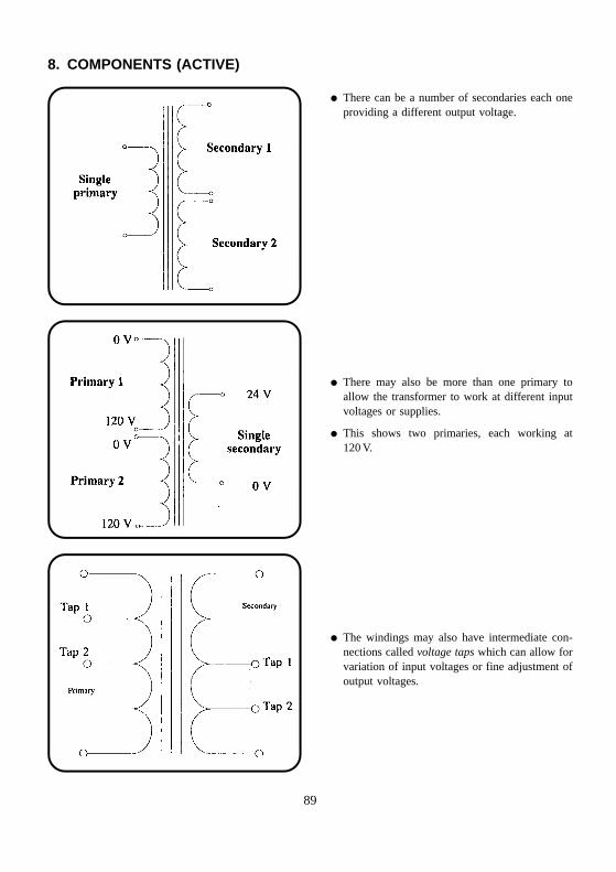
8. COMPONENTS (ACTIVE)
� There can be a number of secondaries each oneproviding a different output voltage.
� There may also be more than one primary toallow the transformer to work at different inputvoltages or supplies.
� This shows two primaries, each working at120 V.
� The windings may also have intermediate con-nections called voltage taps which can allow forvariation of input voltages or fine adjustment ofoutput voltages.
89
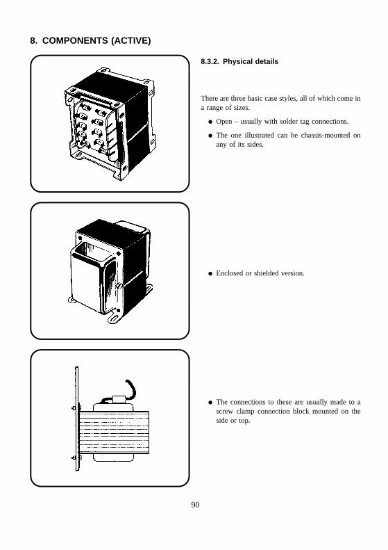
8. COMPONENTS (ACTIVE)
8.3.2. Physical details
There are three basic case styles, all of which come ina range of sizes.
� Open – usually with solder tag connections.
� The one illustrated can be chassis-mounted onany of its sides.
� Enclosed or shielded version.
� The connections to these are usually made to ascrew clamp connection block mounted on theside or top.
90
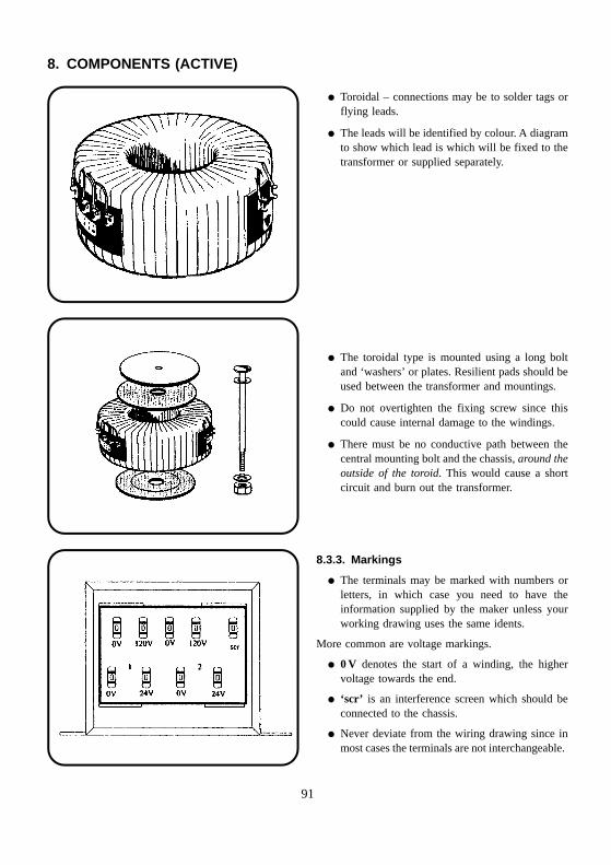
8. COMPONENTS (ACTIVE)
� Toroidal – connections may be to solder tags orflying leads.
� The leads will be identified by colour. A diagramto show which lead is which will be fixed to thetransformer or supplied separately.
� The toroidal type is mounted using a long boltand ‘washers’ or plates. Resilient pads should beused between the transformer and mountings.
� Do not overtighten the fixing screw since thiscould cause internal damage to the windings.
� There must be no conductive path between thecentral mounting bolt and the chassis, around theoutside of the toroid. This would cause a shortcircuit and burn out the transformer.
8.3.3. Markings
� The terminals may be marked with numbers orletters, in which case you need to have theinformation supplied by the maker unless yourworking drawing uses the same idents.
More common are voltage markings.
� 0 V denotes the start of a winding, the highervoltage towards the end.
� ‘scr’ is an interference screen which should beconnected to the chassis.
� Never deviate from the wiring drawing since inmost cases the terminals are not interchangeable.
91
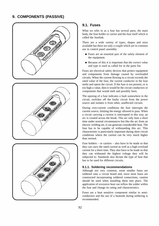
9. COMPONENTS (PASSIVE)
9.1. FusesWhat we refer to as a fuse has several parts, the mainbody, the fuse holder or carrier and the fuse itself which iscalled the fuselink.
There are a wide variety of types, shapes and sizesavailable but there are only a couple which are in commonuse in control panel assembly.
� Fuses are an essential part of the safety element ofthe equipment.
� Because of this it is important that the correct valueand type is used as called for in the parts list.
Fuses are electrical safety devices that protect equipmentand components from damage caused by overloadedcircuits. When the current flowing in a circuit exceeds therated value of the fuse, the current conductor in the fusemelts and opens the circuit. If the fuse is not present, or istoo high a value, then it would be the circuit conductors orcomponents that would melt and possibly burn.
The opening of a fuse indicates a fault somewhere in thecircuit, switches off the faulty circuit from the powersource and isolates it from other, unaffected circuits.
During over-current conditions the fuse interrupts thecurrent source, limiting the energy allowed to pass. Whena circuit carrying a current is interrupted in this way, anarc is created across the break. This arc only lasts a shorttime under normal circumstances but like the arc from anelectric welding set, it can generate considerable heat. Thefuse has to be capable of withstanding this arc. Thischaracteristic is particularly important during short circuitconditions where the current can be very much higherthan normal.
Fuse holders – or carriers – also have to be made so thatthey can carry the rated current as well as a high overloadcurrent for a short time. They also have to be made so thatthey can withstand the highest voltage they will besubjected to. Standards also dictate the type of fuse thathas to be used for different circuits.
9.1.1. Soldering recommendationsAlthough not very common, some smaller fuses aresoldered onto a circuit board and, since most fuses areconstructed incorporating soldered connections, cautionshould be used when installing them into place. Theapplication of excessive heat can reflow the solder withinthe fuse and change its rating and characteristics.
Fuses are a heat sensitive component similar to semi-conductors and the use of a heatsink during soldering isrecommended.
92
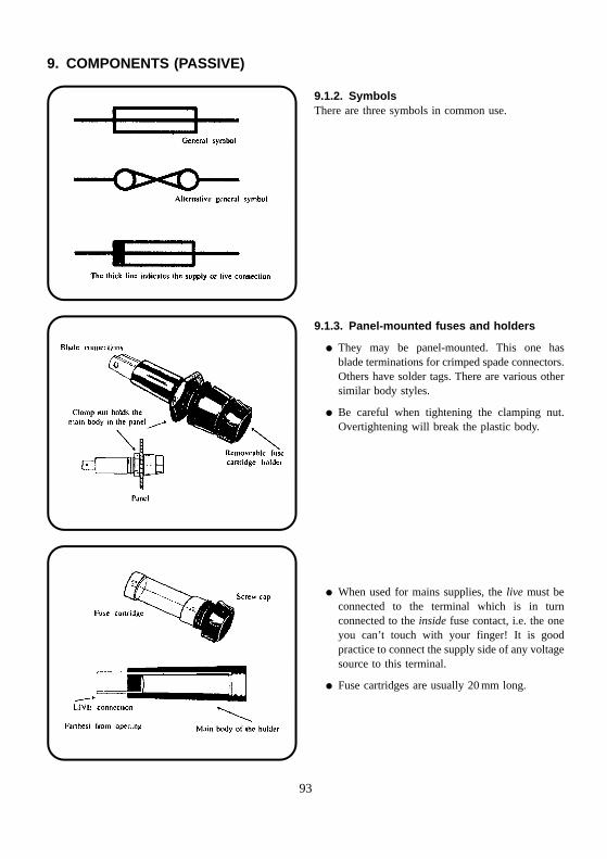
9. COMPONENTS (PASSIVE)
9.1.2. SymbolsThere are three symbols in common use.
9.1.3. Panel-mounted fuses and holders
� They may be panel-mounted. This one hasblade terminations for crimped spade connectors.Others have solder tags. There are various othersimilar body styles.
� Be careful when tightening the clamping nut.Overtightening will break the plastic body.
� When used for mains supplies, the live must beconnected to the terminal which is in turnconnected to the inside fuse contact, i.e. the oneyou can’t touch with your finger! It is goodpractice to connect the supply side of any voltagesource to this terminal.
� Fuse cartridges are usually 20 mm long.
93
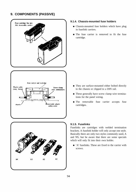
9. COMPONENTS (PASSIVE)
9.1.4. Chassis-mounted fuse holders
� Chassis-mounted fuse holders which have plugin fuselink carriers.
� The fuse carrier is removed to fit the fusecartridge.
� They are surface-mounted either bolted directlyto the chassis or clipped to a DIN rail.
� These generally have screw clamp wire termina-tions for the panel wiring.
� The removable fuse carrier accepts fusecartridges.
9.1.5. FuselinksFuselinks are cartridges with welded terminationbrackets. A fuselink holder will only accept one style.Basically there are only two styles commonly used, Aand NS, but be aware that there are some specialswhich will only fit into their own holder.
� ‘A’ fuselinks. These are fixed to the carrier withscrews.
94
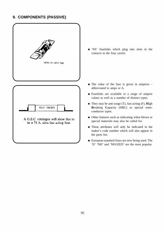
9. COMPONENTS (PASSIVE)
� ‘NS’ fuselinks which plug into slots in thecontacts in the fuse carrier.
� The value of the fuse is given in amperes –abbreviated to amps or A.
� Fuselinks are available in a range of amperevalues as well as a number of distinct types.
� They may be anti-surge (T), fast acting (F), HighBreaking Capacity (HBC) or special semi-conductor types.
� Other features such as indicating when blown orspecial materials may also be called for.
� These attributes will only be indicated in themaker’s code number which will also appear inthe parts list.
� European standard fuses are now being used. The‘D’ ‘NH’ and ‘NEOZED’ are the most popular.
95
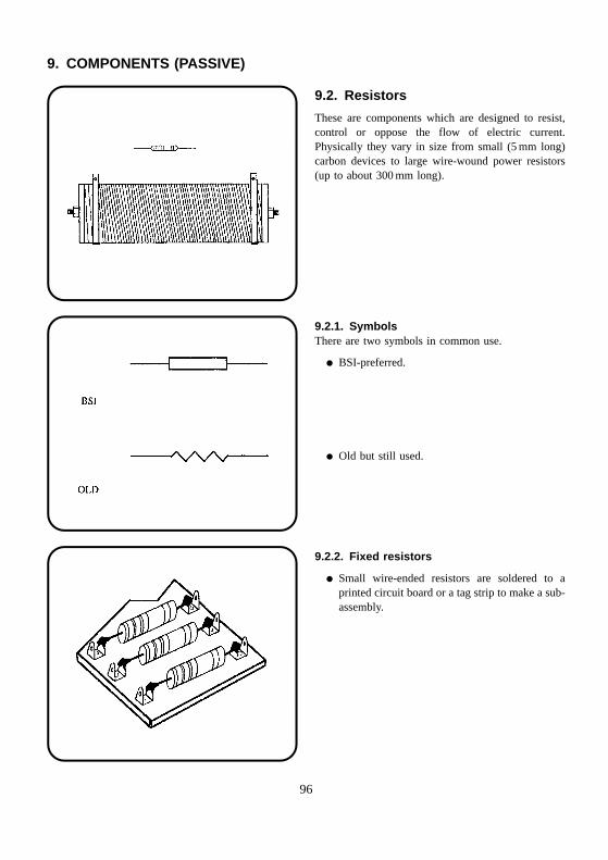
9. COMPONENTS (PASSIVE)
9.2. Resistors
These are components which are designed to resist,control or oppose the flow of electric current.Physically they vary in size from small (5 mm long)carbon devices to large wire-wound power resistors(up to about 300 mm long).
9.2.1. SymbolsThere are two symbols in common use.
� BSI-preferred.
� Old but still used.
9.2.2. Fixed resistors
� Small wire-ended resistors are soldered to aprinted circuit board or a tag strip to make a sub-assembly.
96
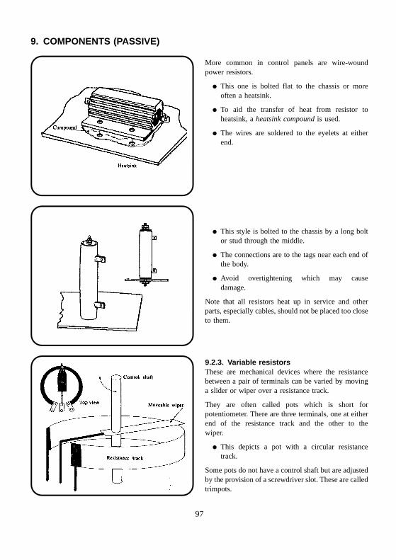
9. COMPONENTS (PASSIVE)
More common in control panels are wire-woundpower resistors.
� This one is bolted flat to the chassis or moreoften a heatsink.
� To aid the transfer of heat from resistor toheatsink, a heatsink compound is used.
� The wires are soldered to the eyelets at eitherend.
� This style is bolted to the chassis by a long boltor stud through the middle.
� The connections are to the tags near each end ofthe body.
� Avoid overtightening which may causedamage.
Note that all resistors heat up in service and otherparts, especially cables, should not be placed too closeto them.
9.2.3. Variable resistorsThese are mechanical devices where the resistancebetween a pair of terminals can be varied by movinga slider or wiper over a resistance track.
They are often called pots which is short forpotentiometer. There are three terminals, one at eitherend of the resistance track and the other to thewiper.
� This depicts a pot with a circular resistancetrack.
Some pots do not have a control shaft but are adjustedby the provision of a screwdriver slot. These are calledtrimpots.
97
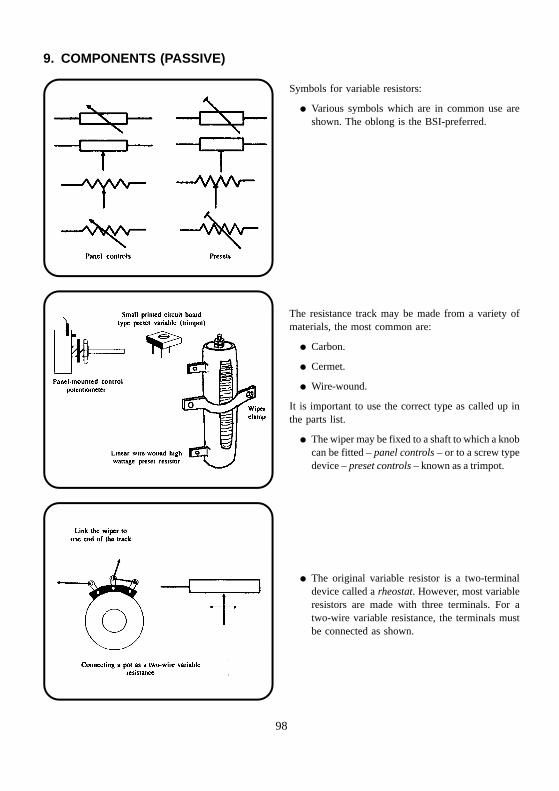
9. COMPONENTS (PASSIVE)
Symbols for variable resistors:
� Various symbols which are in common use areshown. The oblong is the BSI-preferred.
The resistance track may be made from a variety ofmaterials, the most common are:
� Carbon.
� Cermet.
� Wire-wound.
It is important to use the correct type as called up inthe parts list.
� The wiper may be fixed to a shaft to which a knobcan be fitted – panel controls – or to a screw typedevice – preset controls – known as a trimpot.
� The original variable resistor is a two-terminaldevice called a rheostat. However, most variableresistors are made with three terminals. For atwo-wire variable resistance, the terminals mustbe connected as shown.
98
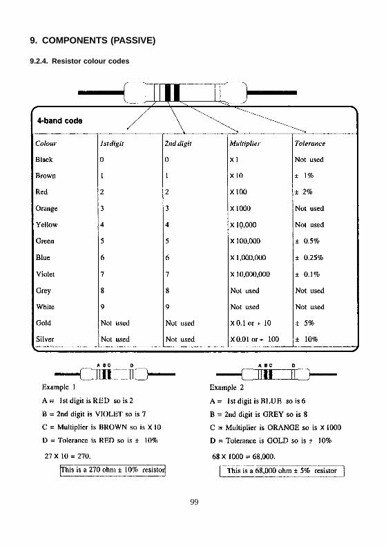
9. COMPONENTS (PASSIVE)
9.2.4. Resistor colour codes
99
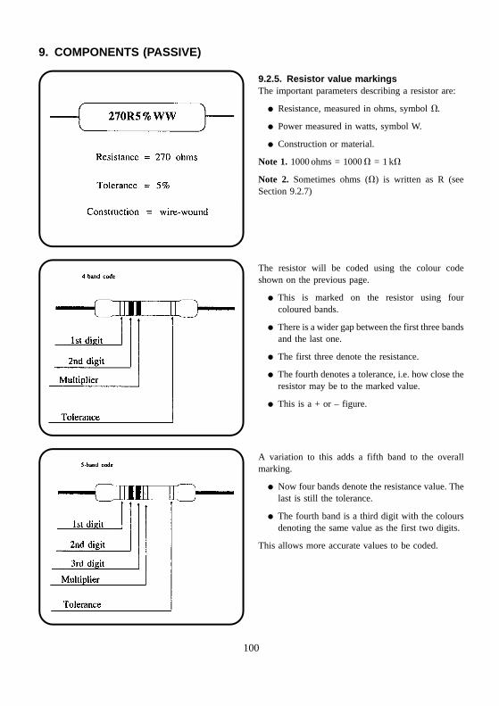
9. COMPONENTS (PASSIVE)
9.2.5. Resistor value markingsThe important parameters describing a resistor are:
� Resistance, measured in ohms, symbol �.
� Power measured in watts, symbol W.
� Construction or material.
Note 1. 1000 ohms = 1000 � = 1 k�
Note 2. Sometimes ohms (�) is written as R (seeSection 9.2.7)
The resistor will be coded using the colour codeshown on the previous page.
� This is marked on the resistor using fourcoloured bands.
� There is a wider gap between the first three bandsand the last one.
� The first three denote the resistance.
� The fourth denotes a tolerance, i.e. how close theresistor may be to the marked value.
� This is a + or – figure.
A variation to this adds a fifth band to the overallmarking.
� Now four bands denote the resistance value. Thelast is still the tolerance.
� The fourth band is a third digit with the coloursdenoting the same value as the first two digits.
This allows more accurate values to be coded.
100
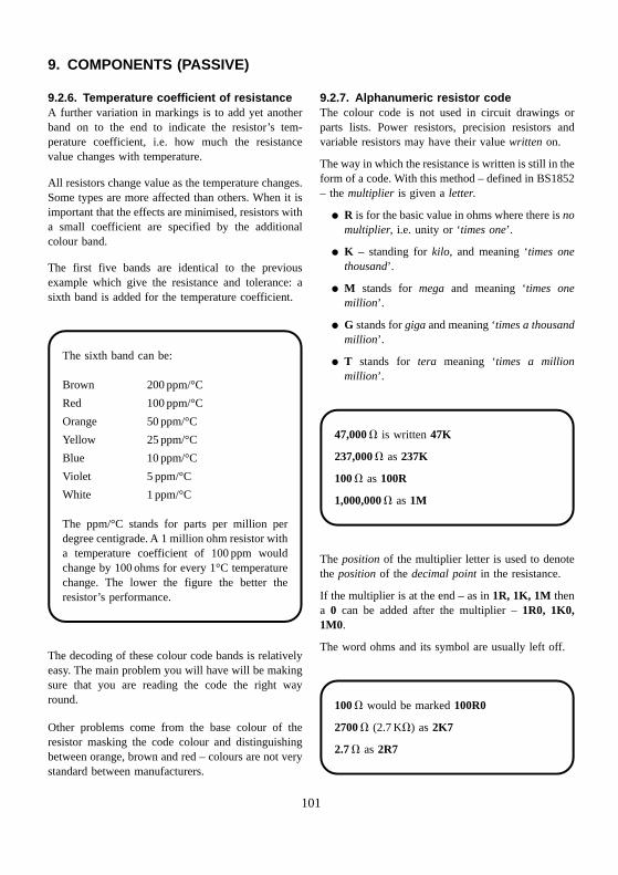
9. COMPONENTS (PASSIVE)
9.2.6. Temperature coefficient of resistanceA further variation in markings is to add yet anotherband on to the end to indicate the resistor’s tem-perature coefficient, i.e. how much the resistancevalue changes with temperature.
All resistors change value as the temperature changes.Some types are more affected than others. When it isimportant that the effects are minimised, resistors witha small coefficient are specified by the additionalcolour band.
The first five bands are identical to the previousexample which give the resistance and tolerance: asixth band is added for the temperature coefficient.
The sixth band can be:
Brown 200 ppm/°C
Red 100 ppm/°C
Orange 50 ppm/°C
Yellow 25 ppm/°C
Blue 10 ppm/°C
Violet 5 ppm/°C
White 1 ppm/°C
The ppm/°C stands for parts per million perdegree centigrade. A 1 million ohm resistor witha temperature coefficient of 100 ppm wouldchange by 100 ohms for every 1°C temperaturechange. The lower the figure the better theresistor’s performance.
The decoding of these colour code bands is relativelyeasy. The main problem you will have will be makingsure that you are reading the code the right wayround.
Other problems come from the base colour of theresistor masking the code colour and distinguishingbetween orange, brown and red – colours are not verystandard between manufacturers.
9.2.7. Alphanumeric resistor codeThe colour code is not used in circuit drawings orparts lists. Power resistors, precision resistors andvariable resistors may have their value written on.
The way in which the resistance is written is still in theform of a code. With this method – defined in BS1852– the multiplier is given a letter.
� R is for the basic value in ohms where there is nomultiplier, i.e. unity or ‘times one’.
� K – standing for kilo, and meaning ‘times onethousand’.
� M stands for mega and meaning ‘times onemillion’.
� G stands for giga and meaning ‘times a thousandmillion’.
� T stands for tera meaning ‘times a millionmillion’.
47,000 � is written 47K
237,000 � as 237K
100 � as 100R
1,000,000 � as 1M
The position of the multiplier letter is used to denotethe position of the decimal point in the resistance.
If the multiplier is at the end – as in 1R, 1K, 1M thena 0 can be added after the multiplier – 1R0, 1K0,1M0.
The word ohms and its symbol are usually left off.
100 � would be marked 100R0
2700 � (2.7 K�) as 2K7
2.7 � as 2R7
101
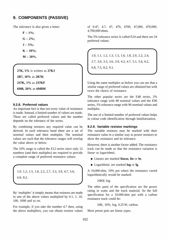
9. COMPONENTS (PASSIVE)
The tolerance is also given a letter:
F – 1%;
G – 2%;
J – 5%;
K – 10%;
M – 20%.
27K, 5% is written as 27KJ
2R7, 10% as 2R7K
237K, 1% as 237KF
6M8, 20% as 6M8M
9.2.8. Preferred valuesAn important fact is that not every value of resistanceis made. Instead, a limited number of values are made.These are called preferred values and the numberdepends on the tolerance of the series.
By combining resistors any required value can bederived. In each tolerance band there are a set ofnominal values and their multiples. The nominalvalues are such that the tolerance ranges will overlapthe value above or below.
The 10% range is called the E12 series since only 12numbers (and their multiples) are required to providea complete range of preferred resistance values:
1.0, 1.2, 1.5, 1.8, 2.2, 2.7, 3.3, 3.9, 4.7, 5.6,
6.8, 8.2.
By ‘multiples’ it simply means that resistors are madein sets of the above values multiplied by 0.1, 1, 10,100, 1000 and so on.
For example, if you take the number 4.7 then, usingthe above multipliers, you can obtain resistor values
of 0.47, 4.7, 47, 470, 4700, 47,000, 470,000,4,700,000 ohms.
The 5% tolerance series is called E24 and there are 24preferred values:
1.0, 1.1, 1.2, 1.3, 1.5, 1.6, 1.8, 2.0, 2.2, 2.4,
2.7, 3.0, 3.3, 3.6, 3.9, 4.3, 4.7, 5.1, 5.6, 6.2,
6.8, 7.5, 8.2, 9.1.
Using the same multiples as before you can see that asimilar range of preferred values are obtained but withtwice the choice of resistance.
The other popular series are the E48 series, 2%tolerance range with 48 nominal values and the E96series, 1% tolerance range with 96 nominal values andmultiples.
The use of a limited number of preferred values helpsin colour code identification through familiarisation.
9.2.9. Variable resistor markingsThe variable resistors may be marked with theirresistance value in a similar way to power resistors toshow the resistance and its tolerance.
However, there is another factor added. The resistancetrack can be made so that the resistance variation islinear or logarithmic.
� Linears are marked linear, lin or ln.
� Logarithmic are marked log or lg.
A 10,000 ohm, 10% pot where the resistance variedlogarithmically would be marked:
10KK log.
The other parts of the specification are the powerrating in watts and the track material. So the fullspecification for a 10,000 ohm pot with a carbonresistance track could be:
10K, 10%, log, 0.25 W, carbon.
Most preset pots are linear types.
102
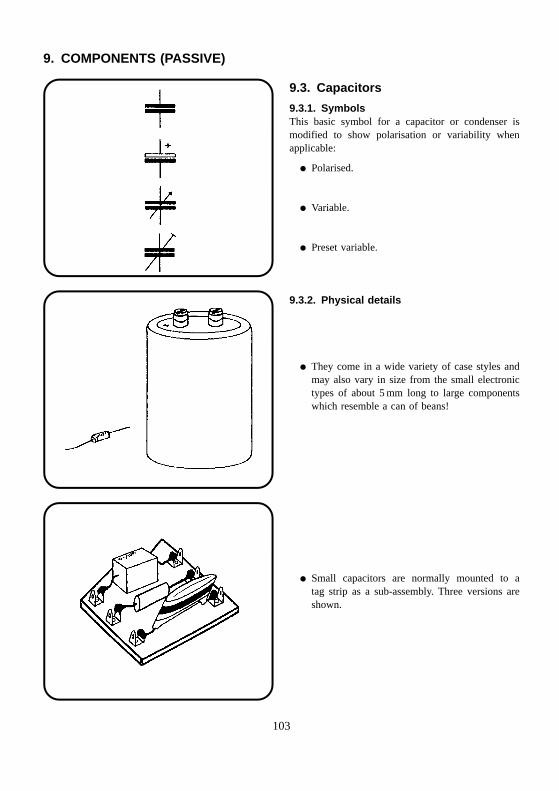
9. COMPONENTS (PASSIVE)
9.3. Capacitors
9.3.1. SymbolsThis basic symbol for a capacitor or condenser ismodified to show polarisation or variability whenapplicable:
� Polarised.
� Variable.
� Preset variable.
9.3.2. Physical details
� They come in a wide variety of case styles andmay also vary in size from the small electronictypes of about 5 mm long to large componentswhich resemble a can of beans!
� Small capacitors are normally mounted to atag strip as a sub-assembly. Three versions areshown.
103
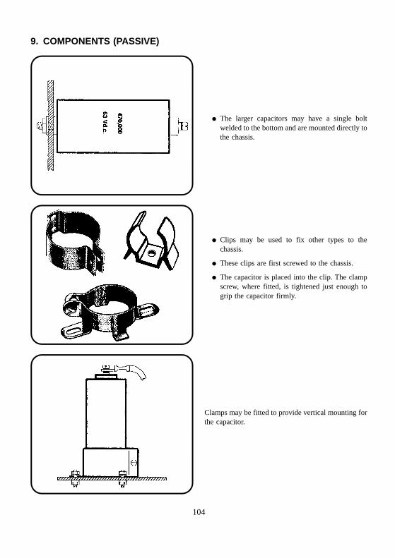
9. COMPONENTS (PASSIVE)
� The larger capacitors may have a single boltwelded to the bottom and are mounted directly tothe chassis.
� Clips may be used to fix other types to thechassis.
� These clips are first screwed to the chassis.
� The capacitor is placed into the clip. The clampscrew, where fitted, is tightened just enough togrip the capacitor firmly.
Clamps may be fitted to provide vertical mounting forthe capacitor.
104
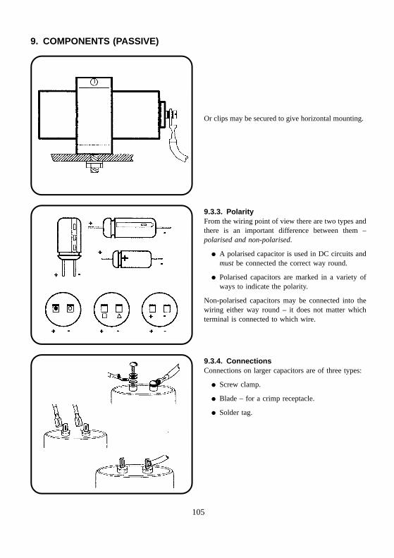
9. COMPONENTS (PASSIVE)
Or clips may be secured to give horizontal mounting.
9.3.3. PolarityFrom the wiring point of view there are two types andthere is an important difference between them –polarised and non-polarised.
� A polarised capacitor is used in DC circuits andmust be connected the correct way round.
� Polarised capacitors are marked in a variety ofways to indicate the polarity.
Non-polarised capacitors may be connected into thewiring either way round – it does not matter whichterminal is connected to which wire.
9.3.4. ConnectionsConnections on larger capacitors are of three types:
� Screw clamp.
� Blade – for a crimp receptacle.
� Solder tag.
105
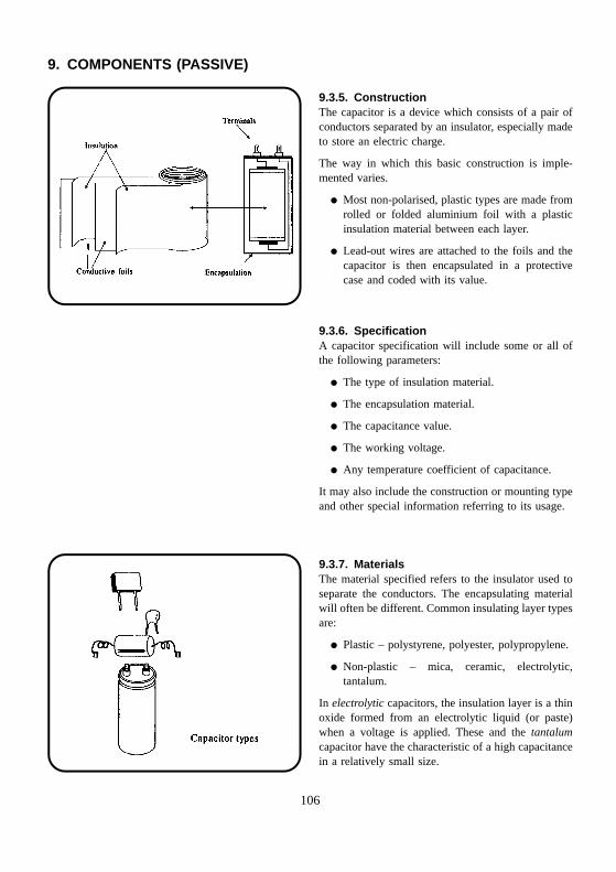
9. COMPONENTS (PASSIVE)
9.3.5. ConstructionThe capacitor is a device which consists of a pair ofconductors separated by an insulator, especially madeto store an electric charge.
The way in which this basic construction is imple-mented varies.
� Most non-polarised, plastic types are made fromrolled or folded aluminium foil with a plasticinsulation material between each layer.
� Lead-out wires are attached to the foils and thecapacitor is then encapsulated in a protectivecase and coded with its value.
9.3.6. SpecificationA capacitor specification will include some or all ofthe following parameters:
� The type of insulation material.
� The encapsulation material.
� The capacitance value.
� The working voltage.
� Any temperature coefficient of capacitance.
It may also include the construction or mounting typeand other special information referring to its usage.
9.3.7. MaterialsThe material specified refers to the insulator used toseparate the conductors. The encapsulating materialwill often be different. Common insulating layer typesare:
� Plastic – polystyrene, polyester, polypropylene.
� Non-plastic – mica, ceramic, electrolytic,tantalum.
In electrolytic capacitors, the insulation layer is a thinoxide formed from an electrolytic liquid (or paste)when a voltage is applied. These and the tantalumcapacitor have the characteristic of a high capacitancein a relatively small size.
106
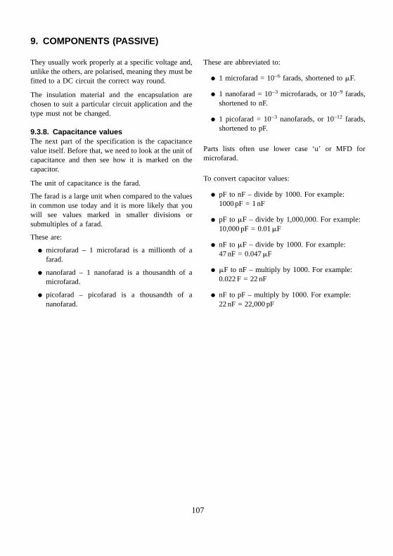
9. COMPONENTS (PASSIVE)
They usually work properly at a specific voltage and,unlike the others, are polarised, meaning they must befitted to a DC circuit the correct way round.
The insulation material and the encapsulation arechosen to suit a particular circuit application and thetype must not be changed.
9.3.8. Capacitance valuesThe next part of the specification is the capacitancevalue itself. Before that, we need to look at the unit ofcapacitance and then see how it is marked on thecapacitor.
The unit of capacitance is the farad.
The farad is a large unit when compared to the valuesin common use today and it is more likely that youwill see values marked in smaller divisions orsubmultiples of a farad.
These are:
� microfarad – 1 microfarad is a millionth of afarad.
� nanofarad – 1 nanofarad is a thousandth of amicrofarad.
� picofarad – picofarad is a thousandth of ananofarad.
These are abbreviated to:
� 1 microfarad = 10–6 farads, shortened to �F.
� 1 nanofarad = 10–3 microfarads, or 10–9 farads,shortened to nF.
� 1 picofarad = 10–3 nanofarads, or 10–12 farads,shortened to pF.
Parts lists often use lower case ‘u’ or MFD formicrofarad.
To convert capacitor values:
� pF to nF – divide by 1000. For example:1000 pF = 1 nF
� pF to �F – divide by 1,000,000. For example:10,000 pF = 0.01 �F
� nF to �F – divide by 1000. For example:47 nF = 0.047 �F
� �F to nF – multiply by 1000. For example:0.022 F = 22 nF
� nF to pF – multiply by 1000. For example:22 nF = 22,000 pF
107
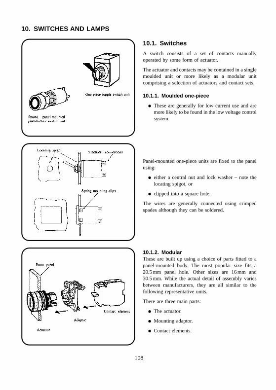
10. SWITCHES AND LAMPS
10.1. Switches
A switch consists of a set of contacts manuallyoperated by some form of actuator.
The actuator and contacts may be contained in a singlemoulded unit or more likely as a modular unitcomprising a selection of actuators and contact sets.
10.1.1. Moulded one-piece
� These are generally for low current use and aremore likely to be found in the low voltage controlsystem.
Panel-mounted one-piece units are fixed to the panelusing:
� either a central nut and lock washer – note thelocating spigot, or
� clipped into a square hole.
The wires are generally connected using crimpedspades although they can be soldered.
10.1.2. ModularThese are built up using a choice of parts fitted to apanel-mounted body. The most popular size fits a20.5 mm panel hole. Other sizes are 16 mm and30.5 mm. While the actual detail of assembly variesbetween manufacturers, they are all similar to thefollowing representative units.
There are three main parts:
� The actuator.
� Mounting adaptor.
� Contact elements.
108
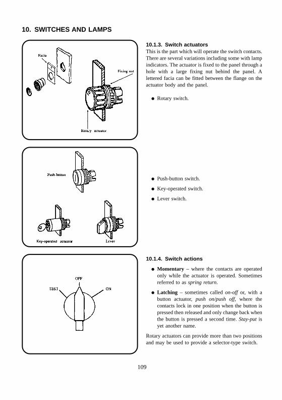
10. SWITCHES AND LAMPS
10.1.3. Switch actuatorsThis is the part which will operate the switch contacts.There are several variations including some with lampindicators. The actuator is fixed to the panel through ahole with a large fixing nut behind the panel. Alettered facia can be fitted between the flange on theactuator body and the panel.
� Rotary switch.
� Push-button switch.
� Key-operated switch.
� Lever switch.
10.1.4. Switch actions
� Momentary – where the contacts are operatedonly while the actuator is operated. Sometimesreferred to as spring return.
� Latching – sometimes called on-off or, with abutton actuator, push on/push off, where thecontacts lock in one position when the button ispressed then released and only change back whenthe button is pressed a second time. Stay-put isyet another name.
Rotary actuators can provide more than two positionsand may be used to provide a selector-type switch.
109
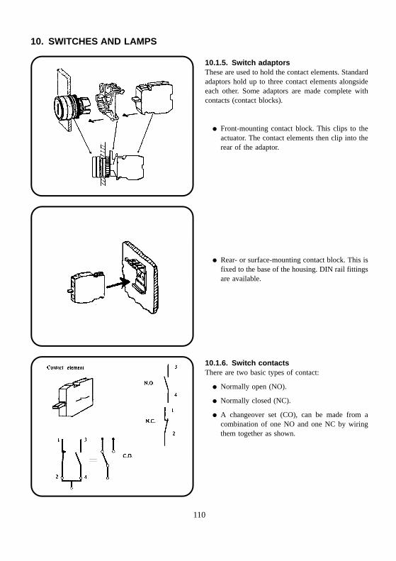
10. SWITCHES AND LAMPS
10.1.5. Switch adaptorsThese are used to hold the contact elements. Standardadaptors hold up to three contact elements alongsideeach other. Some adaptors are made complete withcontacts (contact blocks).
� Front-mounting contact block. This clips to theactuator. The contact elements then clip into therear of the adaptor.
� Rear- or surface-mounting contact block. This isfixed to the base of the housing. DIN rail fittingsare available.
10.1.6. Switch contactsThere are two basic types of contact:
� Normally open (NO).
� Normally closed (NC).
� A changeover set (CO), can be made from acombination of one NO and one NC by wiringthem together as shown.
110
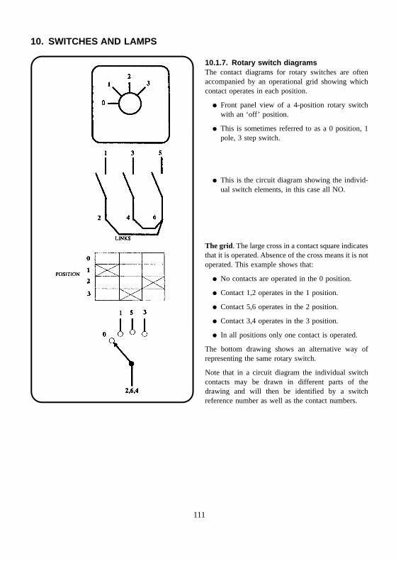
10. SWITCHES AND LAMPS
10.1.7. Rotary switch diagramsThe contact diagrams for rotary switches are oftenaccompanied by an operational grid showing whichcontact operates in each position.
� Front panel view of a 4-position rotary switchwith an ‘off’ position.
� This is sometimes referred to as a 0 position, 1pole, 3 step switch.
� This is the circuit diagram showing the individ-ual switch elements, in this case all NO.
The grid. The large cross in a contact square indicatesthat it is operated. Absence of the cross means it is notoperated. This example shows that:
� No contacts are operated in the 0 position.
� Contact 1,2 operates in the 1 position.
� Contact 5,6 operates in the 2 position.
� Contact 3,4 operates in the 3 position.
� In all positions only one contact is operated.
The bottom drawing shows an alternative way ofrepresenting the same rotary switch.
Note that in a circuit diagram the individual switchcontacts may be drawn in different parts of thedrawing and will then be identified by a switchreference number as well as the contact numbers.
111
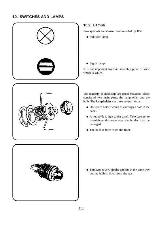
10. SWITCHES AND LAMPS
10.2. Lamps
Two symbols are shown recommended by BSI.
� Indicator lamp.
� Signal lamp.
It is not important from an assembly point of viewwhich is which.
The majority of indicators are panel-mounted. Theseconsist of two main parts, the lampholder and thebulb. The lampholder can take several forms:
� One-piece holder which fits through a hole in thepanel.
� A nut holds it tight to the panel. Take care not toovertighten this otherwise the holder may bedamaged.
� The bulb is fitted from the front.
� This type is very similar and fits in the same waybut the bulb is fitted from the rear.
112
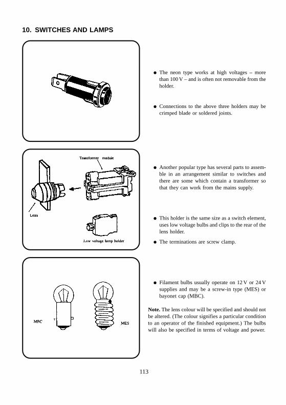
10. SWITCHES AND LAMPS
� The neon type works at high voltages – morethan 100 V – and is often not removable from theholder.
� Connections to the above three holders may becrimped blade or soldered joints.
� Another popular type has several parts to assem-ble in an arrangement similar to switches andthere are some which contain a transformer sothat they can work from the mains supply.
� This holder is the same size as a switch element,uses low voltage bulbs and clips to the rear of thelens holder.
� The terminations are screw clamp.
� Filament bulbs usually operate on 12 V or 24 Vsupplies and may be a screw-in type (MES) orbayonet cap (MBC).
Note. The lens colour will be specified and should notbe altered. (The colour signifies a particular conditionto an operator of the finished equipment.) The bulbswill also be specified in terms of voltage and power.
113
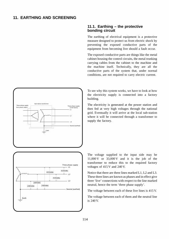
Sub-station transformerThree phase supply Three phase supplyfrom power station to the factory
L1
L2
L3
Neutral (earthed)
Earth
Three phase supplyL1
L2
L3
Neutral (earthed)
Earth
240Volts 240Volts
240Volts
415Volts
415Volts415Volts
11. EARTHING AND SCREENING
11.1. Earthing – the protectivebonding circuit
The earthing of electrical equipment is a protectivemeasure designed to protect us from electric shock bypreventing the exposed conductive parts of theequipment from becoming live should a fault occur.
The exposed conductive parts are things like the metalcabinet housing the control circuits, the metal trunkingcarrying cables from the cabinet to the machine andthe machine itself. Technically, they are all theconductive parts of the system that, under normalconditions, are not required to carry electric current.
To see why this system works, we have to look at howthe electricity supply is connected into a factorybuilding.
The electricity is generated at the power station andthen fed at very high voltages through the nationalgrid. Eventually it will arrive at the local sub-stationwhere it will be connected through a transformer tosupply the factory.
The voltage supplied to the input side may be11,000 V or 33,000 V and it is the job of thetransformer to reduce this to the required factoryvoltages of 415 V and 240 V.
Notice that there are three lines marked L1, L2 and L3.These three lines are known as phases and in effect givethree ‘live’ connections with respect to the line markedneutral, hence the term ‘three phase supply’.
The voltage between each of these live lines is 415 V.
The voltage between each of them and the neutral lineis 240 V.
114
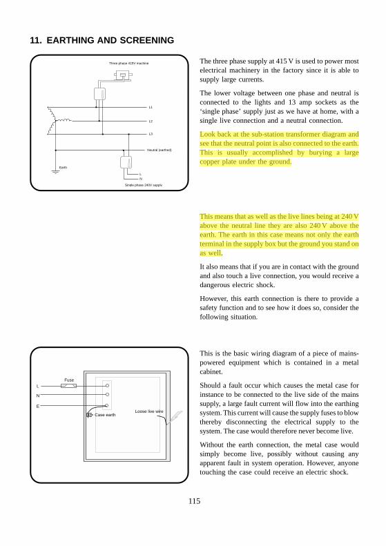
LFuse
Loose live wireCase earth
N
E
Three phase 415V machine
Single phase 240V supply
L1
L2
L3
LN
Neutral (earthed)
Earth
11. EARTHING AND SCREENING
The three phase supply at 415 V is used to power mostelectrical machinery in the factory since it is able tosupply large currents.
The lower voltage between one phase and neutral isconnected to the lights and 13 amp sockets as the‘single phase’ supply just as we have at home, with asingle live connection and a neutral connection.
Look back at the sub-station transformer diagram andsee that the neutral point is also connected to the earth.This is usually accomplished by burying a largecopper plate under the ground.
This means that as well as the live lines being at 240 Vabove the neutral line they are also 240 V above theearth. The earth in this case means not only the earthterminal in the supply box but the ground you stand onas well.
It also means that if you are in contact with the groundand also touch a live connection, you would receive adangerous electric shock.
However, this earth connection is there to provide asafety function and to see how it does so, consider thefollowing situation.
This is the basic wiring diagram of a piece of mains-powered equipment which is contained in a metalcabinet.
Should a fault occur which causes the metal case forinstance to be connected to the live side of the mainssupply, a large fault current will flow into the earthingsystem. This current will cause the supply fuses to blowthereby disconnecting the electrical supply to thesystem. The case would therefore never become live.
Without the earth connection, the metal case wouldsimply become live, possibly without causing anyapparent fault in system operation. However, anyonetouching the case could receive an electric shock.
115
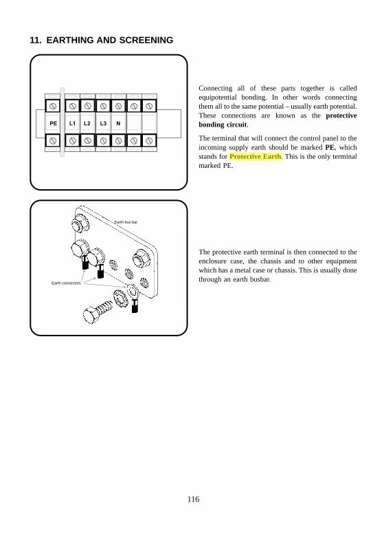
PE L1 L2 L3 N
Earth bus bar
Earth connectors
11. EARTHING AND SCREENING
Connecting all of these parts together is calledequipotential bonding. In other words connectingthem all to the same potential – usually earth potential.These connections are known as the protectivebonding circuit.
The terminal that will connect the control panel to theincoming supply earth should be marked PE, whichstands for Protective Earth. This is the only terminalmarked PE.
The protective earth terminal is then connected to theenclosure case, the chassis and to other equipmentwhich has a metal case or chassis. This is usually donethrough an earth busbar.
116
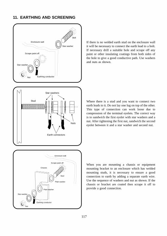
Bolt
Star washer
Scrape paint off
Earthing conductor
Star washer
Nut
Enclosure wall
Stud
Nuts
Star washers
Earth connectors
Stud
Plain washer
Scrape paint off
Enclosure wall
Earthing conductor
Star washer
Nut
Plain washer
Chassis
11. EARTHING AND SCREENING
If there is no welded earth stud on the enclosure wallit will be necessary to connect the earth lead to a bolt.If necessary drill a suitable hole and scrape off anypaint or other insulating coatings from both sides ofthe hole to give a good conductive path. Use washersand nuts as shown.
Where there is a stud and you want to connect twoearth leads to it. Do not lay one lug on top of the other.This type of connection can work loose due tocompression of the terminal eyelets. The correct wayis to sandwich the first eyelet with star washers and anut. After tightening the first nut, sandwich the secondeyelet between it and a star washer and second nut.
When you are mounting a chassis or equipmentmounting bracket to an enclosure which has weldedmounting studs, it is necessary to ensure a goodconnection to earth by adding a separate earth wire.Use the sequence of washers and nut as shown. If thechassis or bracket are coated then scrape it off toprovide a good connection.
117
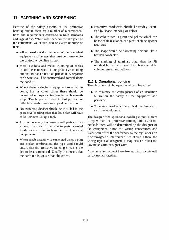
11. EARTHING AND SCREENING
Because of the safety aspects of the protectivebonding circuit, there are a number of recommenda-tions and requirements contained in both standardsand regulations. While most concern the designer ofthe equipment, we should also be aware of some ofthem.
� All exposed conductive parts of the electricalequipment and the machine must be connected tothe protective bonding circuit.
� Metal conduits and metal sheathing of cablesshould be connected to the protective bondingbut should not be used as part of it. A separateearth wire should be connected and carried alongthe conduit.
� Where there is electrical equipment mounted ondoors, lids or cover plates these should beconnected to the protective bonding with an earthstrap. The hinges or other fastenings are notreliable enough to ensure a good connection.
� No switching devices should be included in theprotective bonding other than links that will haveto be removed using a tool.
� It is not necessary to connect small parts such asscrews, rivets and nameplates to parts mountedinside an enclosure such as the metal parts ofcomponents.
� Where a sub-assembly is connected using a plugand socket combination, the type used shouldensure that the protective bonding circuit is thelast to be disconnected. Usually this means thatthe earth pin is longer than the others.
� Protective conductors should be readily identi-fied by shape, marking or colour.
� The colour used is green and yellow which canbe the cable insulation or a piece of sleeving overbare wire.
� The shape would be something obvious like abraided conductor.
� The marking of terminals other than the PEterminal is the earth symbol or they should becoloured green and yellow.
11.1.1. Operational bondingThe objectives of the operational bonding circuit:
� To minimise the consequences of an insulationfailure on the safety of the equipment andpersonnel.
� To reduce the effects of electrical interference onsensitive equipment.
The design of the operational bonding circuit is morecomplex than the protective bonding circuit and themethods used will be determined by the designer ofthe equipment. Since the wiring connections andlayout can affect the conformity to the regulations onelectromagnetic interference, we should adhere thewiring layout as designed. It may also be called thelow-noise earth or signal earth.
Note that at some point these two earthing circuits willbe connected together.
118
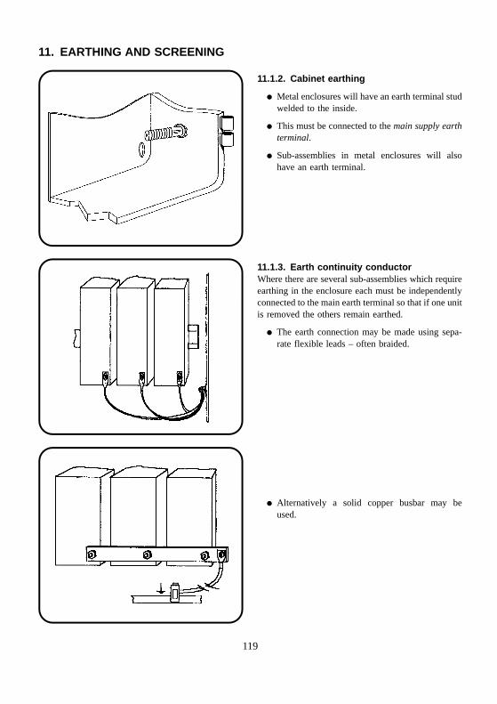
11. EARTHING AND SCREENING
11.1.2. Cabinet earthing
� Metal enclosures will have an earth terminal studwelded to the inside.
� This must be connected to the main supply earthterminal.
� Sub-assemblies in metal enclosures will alsohave an earth terminal.
11.1.3. Earth continuity conductorWhere there are several sub-assemblies which requireearthing in the enclosure each must be independentlyconnected to the main earth terminal so that if one unitis removed the others remain earthed.
� The earth connection may be made using sepa-rate flexible leads – often braided.
� Alternatively a solid copper busbar may beused.
119
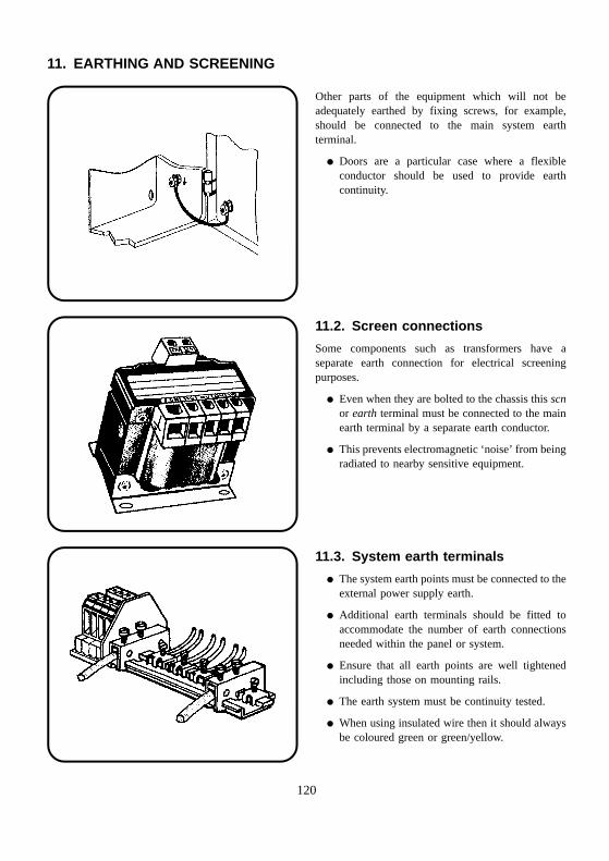
11. EARTHING AND SCREENING
Other parts of the equipment which will not beadequately earthed by fixing screws, for example,should be connected to the main system earthterminal.
� Doors are a particular case where a flexibleconductor should be used to provide earthcontinuity.
11.2. Screen connections
Some components such as transformers have aseparate earth connection for electrical screeningpurposes.
� Even when they are bolted to the chassis this scnor earth terminal must be connected to the mainearth terminal by a separate earth conductor.
� This prevents electromagnetic ‘noise’ from beingradiated to nearby sensitive equipment.
11.3. System earth terminals
� The system earth points must be connected to theexternal power supply earth.
� Additional earth terminals should be fitted toaccommodate the number of earth connectionsneeded within the panel or system.
� Ensure that all earth points are well tightenedincluding those on mounting rails.
� The earth system must be continuity tested.
� When using insulated wire then it should alwaysbe coloured green or green/yellow.
120
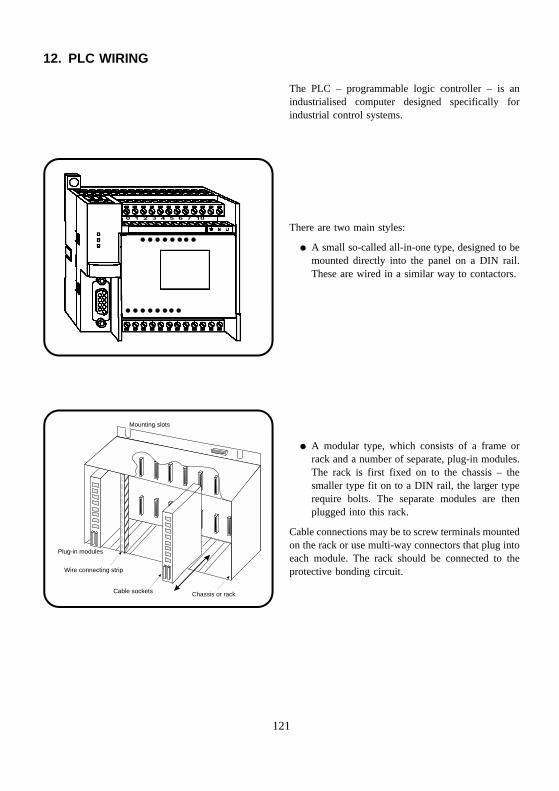
0 1 2 3 4 5 6 7 10
Plug-in modules
Chassis or rack
Mounting slots
Cable sockets
Wire connecting strip
12. PLC WIRING
The PLC – programmable logic controller – is anindustrialised computer designed specifically forindustrial control systems.
There are two main styles:
� A small so-called all-in-one type, designed to bemounted directly into the panel on a DIN rail.These are wired in a similar way to contactors.
� A modular type, which consists of a frame orrack and a number of separate, plug-in modules.The rack is first fixed on to the chassis – thesmaller type fit on to a DIN rail, the larger typerequire bolts. The separate modules are thenplugged into this rack.
Cable connections may be to screw terminals mountedon the rack or use multi-way connectors that plug intoeach module. The rack should be connected to theprotective bonding circuit.
121
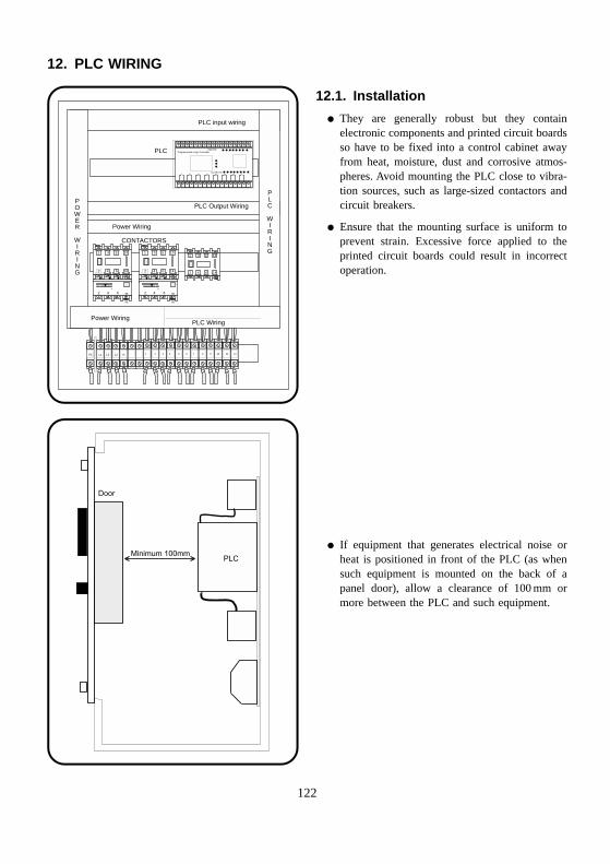
Programmable Logic Controller
L N E + 0 1 2 3 4 5 6 7 10 11 12 13
INPUTS
OUTPUTS
1
2
3
4
5
6
13
14
A
2 4 6 95
96
1
2
3
4
5
6
13
14
A
2 4 6 95
96
1 2 3 7 8 94 5 6 10 11 12PE L1 L2 L3 N
1
2
3
4
5
6
13
14
PLC
PLC input wiring
PLC Output Wiring
PLC Wiring
Power Wiring
Power Wiring
CONTACTORS
PLC
WIRING
POWER
WIRING
Minimum 100mmPLC
Door
12. PLC WIRING
12.1. Installation
� They are generally robust but they containelectronic components and printed circuit boardsso have to be fixed into a control cabinet awayfrom heat, moisture, dust and corrosive atmos-pheres. Avoid mounting the PLC close to vibra-tion sources, such as large-sized contactors andcircuit breakers.
� Ensure that the mounting surface is uniform toprevent strain. Excessive force applied to theprinted circuit boards could result in incorrectoperation.
� If equipment that generates electrical noise orheat is positioned in front of the PLC (as whensuch equipment is mounted on the back of apanel door), allow a clearance of 100 mm ormore between the PLC and such equipment.
122
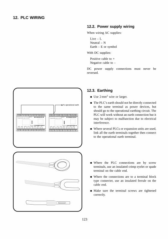
Programmable Logic Controller
L N E + 0 1 2 3 4 5 6 7 10 11 12 13
INPUTS
OUTPUTS
Programmable Logic Controller
L N E + 0 1 2 3 4 5 6 7 10 11 12 13
INPUTS
OUTPUTS
To operational earth
12. PLC WIRING
12.2. Power supply wiring
When wiring AC supplies:
Live – LNeutral – NEarth – E or symbol
With DC supplies:
Positive cable to +Negative cable to –
DC power supply connections must never bereversed.
12.3. Earthing
� Use 2 mm2 wire or larger.
� The PLC’s earth should not be directly connectedto the same terminal as power devices, butshould go to the operational earthing circuit. ThePLC will work without an earth connection but itmay be subject to malfunction due to electricalinterference.
� Where several PLCs or expansion units are used,link all the earth terminals together then connectto the operational earth terminal.
� Where the PLC connections are by screwterminals, use an insulated crimp eyelet or spadeterminal on the cable end.
� Where the connections are to a terminal blocktype connecter, use an insulated ferrule on thecable end.
� Make sure the terminal screws are tightenedcorrectly.
123

12. PLC WIRING
12.4. Wiring of inputs and outputs
� It is advisable to keep the input and output (I/O)lines separated from each other if possible.
� When the I/O signal wires cannot be separatedfrom the power wiring, use shielded multi-corecable earthed at the PLC end.
� I/O signal wires should be kept at least 100 mmaway from high-voltage and large-current, powercircuit wiring.
124

INDEX
Accidents, 1Active components, 76Actuators, switch, 109Auxiliary contacts, 84
Barrier strips, 75Battery symbols, 16Block diagrams, 8BNC coaxial plug, 43Bootlace ferrules, 37Breakouts, cableforms, 53British Standards Institute, 4Building safe equipment, 4Bulbs, 113Busbar, 116, 119
Cabinet earthing, 119Cable forming, 47
markers, 60preparation, 19strippers, 21ties, 56types, 17
Cableform binding, 48Cableforms, 47Cables, 17
coaxial, 19connections, 62multiway, 20routing, 62
Capacitance values, 107Capacitors, 103
clips, 104polarity, 105symbols, 103
Checking solder joints, 30Checking your soldering iron, 32Circuit diagrams, 7Clip-on terminals, 72Coaxial cable termination, 41
cable stripping, 41plug, fitting, 43socket, fitting, 46wire, 19
Colour code, resistors, 99
Component mounting rails, 68Components (active), 76Components (passive), 92Conductors, 18Connections, capacitors, 105Connector blocks, 72Connectors and terminals, 75Contactors, 76–83
DIN rail, 83interlocks, 84labelling, 86protective units, 85
Contacts, switch, 13, 110Crimp connectors, 34Crimped joints, 34Crimping tools, 35
Diagrams, wiring, 7DIN rail, 68
contactors, 83relays, 81
Diodes symbols, 15Drawings, wiring, 7
Earth continuity conductor, 119Earthing and screening, 115Electric shock, 2Electrical equipment, safety, 3
fires, 2symbols, 9
Extinguishers for electrical fires, 2Eyelets, 39
Ferrules, bootlace, 37Fire drill, 2Fire extinguishers, 2First aid, 1Fixed resistors, 96Forming cables, 47
wires, 29Fuse holders, 93Fuselinks, 94Fuses, 92
125

Hand tools, crimping, 36Hardware, 68Health and Safety Regulations, 1
IEE Regulations, 6Inductors, symbols, 10Inspection, crimped joints, 39
lacing, 56solder joints, 30
Insulation materials, 17removal, 21
Interlocks, contactors, 84
Knots, lacing, 49
Labelling, cables, 60contactors, 86relays, 82transformers, 91
Lacing, cableforms, 47Lacing, cord, 48
knots, 49ties, 56
Lamps, 108Lock stitch, 50
Making an insulated pigtail, 42Markers, cable, 60Mounting rails, 68Multiway cables, 20
Operational bonding, 118
Parts list, 8Passive components, 92Pigtail connections, 41PLC:
installation, 122earthing, 123power supply, 123
Polarity, capacitors, 105
Power control relays, 82Preferred values, resistors, 102Preparation, wire, 17Protective bonding, 62, 114Protective earth, 114, 116Protective units, contactors, 85
Rectifier symbols, 14Relay contacts symbols, 79
operating coil symbols, 78Relays, 76
DIN rail, 81labelling, 82power control, 82
Resistor colour code, 99value markings, 100
Resistors, 96symbols, 11, 96wire-wound, 96
Rotary switch diagrams, 111Run-out sheet, 48
Safety, electrical, 1crimping tools, 37soldering, 33
Screen connections, 120Screened wire, 19Screening, 118Screw clamp terminals, 40Screw terminals, 75Solder, 28Soldering and termination, 26
equipment, 26irons, 26stranded wire, 31
Spade connectors, 39Specification, capacitors, 106
wire, 18Standard Wire Gauge, 19Standards:
BS EN 60204, 4BS EN 60947, 4
Start knots, 49Strippers, cable, 24Stripping coaxial cable, 41
126
Switch actuators, 109adaptors, 110contacts, 110types, 108
Switches, 108Symbols, 9
batteries, 16capacitors, 12,conductors, 9connectors, 10diodes, 15fuses, 12,inductors, 10rectifiers, 14relays, 78resistors, 11,switch contacts, 13, 110switches, rotary, 111transformers, 88
System earth terminals, 120
Temperature coefficient of resistance, 101Template, cableforms, 47Terminals, 8
clip-on, 72screw, 40, 70
Terminations, 26coaxial, 41
Ties, cable, 56Tools, soldering, 26Transformers, 88
markings, 91symbols, 10, 88toroidal, 91
Trunking, plastic, 69Twisted pairs, 58
Variable resistor markings, 102Variable resistors, 97
Wire forming, 29preparation, 21soldering, 26specifications, 18twisted pairs, 58types, 17
Wire-wound resistors, 96Wiring diagram, 7
schedule, 8, 47tools, 21
Working practice, 3
127