gsm cell-phone monitoring & control...
TRANSCRIPT
Version 5.2
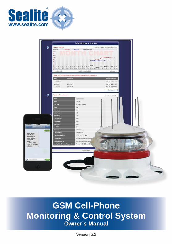
GSM Cell-Phone Monitoring & Control System
Owner’s Manual

Version No. Description Date Author Approved1.0 Manual Launch July 2006 C. Procter1.1 Addition of active current feature Nov 2007 J. Procter1.2 Addition of new G24 features Jan 2009 A. Burns1.3 Update warranty listing May 2009 K. Paton1.4 Added get & set applications Aug 2009 A. Dixon2.0 Addition of new Q2687 features March 2012 A. Burns2.1 Web Report Update April 2012 K. Paton3.0 Update to GSM Portal Sept 2012 Y. Chambers4.0 Update to screen captures Feb 2014 Y. Chambers4.1 Appendix: Wiring diagrams August 2015 Y. Chambers5.0 Update web reporting number October 2015 Y. Chambers5.1 Update: Contact details April 2016 J. Dore5.2 Update Commands, Update Alarms
for GSM, Update Installation details for SIM Card,
September 2016 A.Dixon M.Nicholson
Disclaimer:It is the customer’s responsibility to check with their service provider (prior to installation) to ensure there is network coverage in the area in which the lantern(s) will be installed. Sealite Pty Ltd will not be held responsible if the network coverage of the service provider should fail.

Latest products and information available at www.sealite.com3
GSM Cell-PhoneMonitoring & Control System
Table of Contents
Introduction ..........................................................................................Page 4
System Components ...........................................................................Page 5
Getting Started: Setting up your GSM Module .................................Page 6Step 1: Purchase, Record & Insert SIM Card into Lantern ..............Page 7Step 2: Program Cell Phone Access List, Web Reporting & Essential Commands ............................................................Page 9Step 3: Program Desired Cell Phone Report List & Alarms ..........Page 12Accessing your Lantern’s Data ........................................................Page 16
The add Command ............................................................................Page 18
The list Command .............................................................................Page 20
The delete Command ........................................................................Page 21
The get Command .............................................................................Page 22
The set Command .............................................................................Page 23
Step 4: Accessing the Sealite GSM Web Portal ..............................Page 26 CREATE A GSM ACCOUNT .....................................................Page 26 GSM Dashboard........................................................................Page 29 CONFIGURATION ........................................................Page 30 DEPLOYMENT MAP ....................................................Page 41 REQUEST HELP ..........................................................Page 43 CHANGE PASSWORD .................................................Page 45
Lantern Installation Location ...........................................................Page 47
Trouble Shooting ...............................................................................Page 49 Trouble Shooting Table..............................................................Page 50 Lantern Board Indicator / Status LEDs ......................................Page 51 Phone Module Indicator / Status LEDs .....................................Page 52
Appendix ............................................................................................Page 54 Wiring Diagrams ........................................................................Page 55
Sealite Lantern Warranty ..................................................................Page 57

Latest products and information available at www.sealite.com4
GSM Cell-PhoneMonitoring & Control System
IntroductionWelcome to GSM monitoring and control of your marine lanterns. The Sealite GSM Monitoring and Control System is a complete integrated module designed to allow convenient monitoring of Sealite lanterns using a cellular telephone and web access from remote locations that have GSM network coverage. The GSM circuit monitors the data from the lantern and will report to designated cell phones a number of pre-programmed alarm conditions if they occur.
The GSM System is internally housed within the Sealite lantern and requires no external aerials – providing convenient installation and retaining the IP68 waterproof rating of the lantern.
The user can also send an SMS text message to the designated Sealite lantern to receive a status report from the lantern by return SMS text message. In addition, the user has complete control over the types of alarms received should a fault occur, as well as an array of remote control options including operational mode, flash code and intensity settings.
The user can also set the lantern up to regularly report to a secure area of the Sealite website (the Sealite web gateway). This will provide details of your lanterns operation and it’s GPS position and includes historical graphed statistics of each lantern.
All functions can be programmed into the remote lantern by sending an appropriate SMS text message from a designated cell phone.
Tracking a drifting buoy or alerting to a potential power disruption has never been easier.
The Sealite GSM Monitoring and Control System is secure – unauthorised access to the lanterns data cannot occur as only the designated cell phone numbers programmed into the light will respond to a remote SMS text message.
Data transferred to and maintained on the Sealite website is user password protected.
Key Features:• Access of current lantern status at any time by sending an SMS text message to the lantern from
any designated cell phone number. The lantern status is sent by return SMS text message;• Regular reporting of lantern status to designated cell phone numbers and/or web server; • Reports any pre-programmed alarm condition to designated cell phone numbers, and/or email
addresses;• Remote control of lantern features by sending an SMS text message to the lantern including flash
& intensity setting and operation mode;.• Versatile configuration allows lanterns with or without GPS modules fitted to be monitored
remotely.
Available Data from Remote Lantern:• Battery voltage • Solar module charging current • Lantern current draw • Lantern position - Latitude and Longitude (including ‘off-station’ facility)• Day/night on status• Current operation mode• Current flash code setting• Current intensity setting
SL96 model

Latest products and information available at www.sealite.com5
GSM Cell-PhoneMonitoring & Control System
System Components
All components of the GSM Receiver / Transmitter are enclosed within the Sealite lantern body.
The SL48 & SL96 models have the components of the GSM Receiver / Transmitter enclosed within the top module of the light and have an external aerial.
SL48 model
SL96 model

Latest products and information available at www.sealite.com6
GSM Cell-PhoneMonitoring & Control System
Getting Started:Setting up your GSM Monitoring and Control Module
Setup of the Sealite GSM Monitoring and Control System is a simple 4-step process, outlined below;
• Similar to a cell-phone, a valid SIM card needs to be acquired and inserted into the GSM module prior to use (see “Purchasing a SIM Card” section of this manual). Refer to Installing the Sim Card section of this manual for a step-by-step guide to installing your SIM card.
• The access list is a list of cell phone numbers from which the Sealite GSM Monitoring and Control System will accept configuration commands and report requests. Web reporting and essential commands may also be setup at this step.
• The report list is the list of cell phone numbers which the lantern may send any SMS text message alarm report to. Alarm emails may also be activated from Sealite’s secure GSM Web Portal.
• By sending a report to the Web gateway and providing access via the Sealite website, historical data and graphs may be viewed on each lantern.
STEP 4:Accessing the Sealite
GSM Web Portal
STEP 3:Program Desired Cell Phone Reporting List and Alarms
GSM Monitoring & Control System Ready for Operation
STEP 2:Program Cell Phone Access
List, Web Reporting and Essential Commands
STEP 1:Purchase, Record and Insert SIM Card into GSM Lantern
Getting Started:Setting up your GSM Module

Latest products and information available at www.sealite.com7
GSM Cell-PhoneMonitoring & Control System
STEP 1: Purchase, Record and Insert SIM Card into GSM Lantern
Purchasing a SIM Card and Recording Details
One SIM card is required per lantern and can be purchased from your local telecommunications dealer. You may decide to purchase a pre-paid SIM card, or set the SIM card up on a plan (this is similar to purchasing a new cell phone). Sealite’s GSM enabled lanterns require a Mini-SIM or 2FF SIM Card with a 6 pin contact arrangement.
Each lantern with GSM Monitoring and Control System will have an individual cell phone number. This number is unique to the lantern and should be recorded for reference purposes against the lantern it is installed in. To assist in recognition it is advisable that a description be included as well as the number (For example, Port Beacon #12, +61400123456). A similar recording in user cell phones will assist in identifying lantern installations to which SMS text message commands are sent (the same process as adding a new contact in your cell phone address book).
Ensure the SIM card is unlocked prior to installing into the lantern.
RIGHT:
Mini-SIM or 2FF SIM Card (2nd Form Factor)- 6 pin contact arrangement
WRONG:- 8 pin contact arrangement

Latest products and information available at www.sealite.com8
GSM Cell-PhoneMonitoring & Control System
1. Remove the 6 retaining screws from the cover on the underside of the light, to gain access to the GSM compartment.
2. Open the SIM Card holder.
Installing the Sim Card
Pic 1.
Pic 2.
Pic 3.
3. Position the SIM into the holder. Make sure the SIM Card is positioned correctly. Make sure the SIM Card is ‘Unlocked’ before inserting in
the holder (ie. the SIM card password has been disabled).
4. Fold the SIM Card holder and push it forward into the closed position
5. Replace the 6 retaining screws to close the GSM
compartment. Make sure the rubber seal in positioned correctly before
fitting the cover.

Latest products and information available at www.sealite.com9
GSM Cell-PhoneMonitoring & Control System
STEP 2:Program Cell Phone Access List, Web Reporting & Essential Commands
The Access List is a list of cell phone numbers from which the Sealite GSM Monitoring and Control System will accept configuration commands and report requests. Web reporting and essential commands may also be setup at this step. Follow the process below to program the Access List, Web Reporting and Essential Commands;
• The lantern will accept the first cell phone contact for instructions.
• The first instruction must be correct as the lantern will then only respond to the access cell phone number(s) given.
Two numbers should be provided to the lantern to ensure there is a backup access**.
• “+” and the country code (eg. 61 for Australia, or 44 for U.K) are required to establish the country prefix in which the GSM unit is to operate in. Additional cell phone numbers can then be added by sending commands from those numbers given access.
• For example, to add an Australian cell phone number to the access list the SMS text message command would be: add access +61400987654
All additional telephone numbers added to the access list must be in the international format.
• Once the number has been added to the access list the Sealite GSM Monitoring and Control System will accept commands from these numbers and acknowledge confirmation via reply SMS text message.
• This command initiates the daily web reporting, which sends a daily diagnostic update to be viewed from your secure login at the Sealite Website.
Enable web reporting by sending the SMS text message:-
add autoreport web or
add alarm web
Add cell phone numbers to the permitted access list by sending the SMS text message:-
add access +(country code)(phone number)
More than 1 cell phone number can be included in the SMS text message. To do this separate each
cell phone number with a ‘comma’ character.
Select a cell phone from which the GSM Monitoring and Control System module will be
activated.
Only phone numbers listed in the Access List will be able to “Set” and “Get” lantern information.**In the event that the access cell phone number(s) is lost or no longer in service, Sealite can reset the lantern from the factory if required.

Latest products and information available at www.sealite.com10
GSM Cell-PhoneMonitoring & Control System
From an authorized Access Cell Phone send a new SMS with text message ‘status’ or ‘report’ to the designated SIM card number of your GSM lantern.
Within a few minutes expect a reply in similar format as the following:
------------------------------------------Status ReportVolts: 14.1VCharge: 0.33AMode: Dusk to DawnFCode: 051NightLat: 38 13.2988 S (Latitude 38° 13.2988’)Long: 145 10.8529 E (Longitude145° 10.8529’)OnStation------------------------------------------Note: The actual layout of the message is dependent on your cell phone screen.
User Case #1: Setting up the lantern to report an alarm to a cell phoneIn this example, a cell phone with the phone number +61491570166 is used to enable the alarm function low battery. When the alarm condition occurs, the lantern will alert cell phone +61491570156.
Note: it is allowable to assign a different cell phone number to receive the alarm reports.
The following messages will be texted to the lantern:add access +61491570166add report +61491570156add alarm batlo
SMS text message to Lantern
SMS text message received on cell phone Comment
Step 1 Configures the lantern to allow com-mands Note: The cell number must be formatted as: +(country code)(phone number)
Step 2 When an alarm condition occurs, a text message will be sent to phone number. Note it is allowable to as-sign a different cell phone number to receive the alarm reports.
Step 3 The lantern will send a text message to all phone numbers in the report list when the battery voltage falls below 11.7V.

Latest products and information available at www.sealite.com11
GSM Cell-PhoneMonitoring & Control System
User Case #2: Setting up the lantern to report to the Sealite web gatewayIn this example, a cell phone with the phone number +61491570166 will configure the lantern to send daily reports to the Sealite web gateway (+61418569242).
The following messages will be texted to the lantern:add access +61491570166add web +61418569242add autoreport web
Notes:1. In order to view web reports, please refer to “Accessing the Sealite Web Reports” section of this
manual.2. If the lantern is located outside of Australia, the lantern’s SIM card will need permission to be send text
internationally. Please consult with your SIM card provider to ensure that this feature is enabled.
SMS text message to Lantern
SMS text message received on cell phone Comment
Step 1 Configures the lantern to allow com-mands Note: The cell number must be formatted as: +(country code)(phone number)
Step 2 When an alarm condition occurs, a text message will be sent to the Sealite web gateway.This the phone number for Sealite’s web gateway.
Step 3 Enables a daily web report to be sent to the Sealite web gateway number

Latest products and information available at www.sealite.com12
GSM Cell-PhoneMonitoring & Control System
An alarm is an SMS text message which is sent after a preset alarm condition programmed into the lantern is triggered. Care should be taken when selecting suitable alarms as they can generate large numbers of SMS text messages if not carefully selected. The report list establishes the cell phone numbers that the alarms will be sent to.
Programming Report List The following process will create a list of approved cell phone numbers from which desired alarm reports will be sent;
• This creates an authorised list of cell phone numbers belonging to staff, on-call company maintenance officers or contractors.
• For example, to add an Australian cell phone number to the report list the SMS text message command would be: add report +61400987654
• The SMS text message ‘report’ sent from on-call company maintenance officers or contractors in this list will now generate the standard report SMS text message reply from the lantern.
A successful update will result in an SMS text message reply:-
Report List +(designated cell phone numbers)
The designated cell phone number has now been added to the ‘report’ list. The Sealite GMS module will now accept an SMS text message request for
status ‘report’ from this number.
Use a cell phone in the access list to create the report list by sending the SMS text message:-
add report +(country code)(phone number)
More than 1 cell phone number can be included in the SMS text message. To do this separate each
cell phone number with a ‘comma’ character.
A typical response SMS text message report message from a lantern will display as below:------------------------------------------List Report+61400111222------------------------------------------Note: The actual layout of the message is dependent on your cell phone screen.
STEP 3:Program Desired Cell Phone Report List & Alarms
Latest products and information available at www.sealite.com13
GSM Cell-PhoneMonitoring & Control System
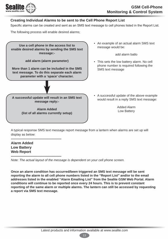
Creating Individual Alarms to be sent to the Cell Phone Report List Specific alarms can be created and sent as an SMS text message to cell phones listed in the Report List.
The following process will enable desired alarms;
• An example of an actual alarm SMS text message would be:
add alarm batlo
• This sets the low battery alarm. No cell phone number is required following the SMS text message
• A successful update of the above example would result in a reply SMS text message:
Added Alarm Low Battery
A successful update will result in an SMS text message reply:-
Alarm Added (list of all alarms currently setup)
Use a cell phone in the access list to enable desired alarms by sending the SMS text
message:-
add alarm (alarm parameter)
More than 1 alarm can be included in the SMS text message. To do this separate each alarm
parameter with a ‘space’ character.
A typical response SMS text message report message from a lantern when alarms are set up will display as below:------------------------------------------Alarm Added Low BatteryWeb Report------------------------------------------Note: The actual layout of the message is dependent on your cell phone screen.
Once an alarm condition has occurred/been triggered an SMS text message will be sent reporting the alarm to all cell phone numbers listed in the “Report List” and/or to the email addresses listed in the enabled “Alarm Emailing List” from the Sealite GSM Web Portal. Alarm conditions will continue to be reported once every 24 hours. This is to prevent constant reporting of the same alarm or multiple alarms. The lantern can still be accessed by requesting a report via SMS text message.

Latest products and information available at www.sealite.com14
GSM Cell-PhoneMonitoring & Control System
Alarm Sources Summary All of the following alarm conditions can be programmed via SMS text message to be either ENABLED or DISABLED. If an alarm condition that has been enabled occurs, an SMS text message will be automatically sent to all the cell phone numbers listed in the Report List.
Command Parameter Function
Enable Command
Format
Disable Command
Format
add alarm
batlo Alarm SMS “batlo” is asserted when the battery voltage falls to a low level (flat battery). An alarm condition will be set if the system battery voltage falls below 10.0V indicating a flat battery. The lantern will be turned OFF if the battery voltage falls below 10.0V.
add alarm batlo
delete alarm batlo
nodata Alarm SMS “nodata” is asserted when the GSM module loses communication with the lantern circuitry.
add alarm nodata
delete alarm nodata
LED Failure Alarm SMS LED Failure is asserted when an individual LED in the lantern fails and the lantern sends a signal to the GSM. NOTE: only available on certain lanterns.
add alarm ledfail
Delete alarm ledfail
rotation Alarm SMS Rotation is asserted when the external rotation sensor detects a failure in a 3rd Party Rotating Table. The Lantern sends a signal to the GSM. NOTE: only available on certain lanterns
add alarm rotation
Delete alarm rotation
temp Alarm SMS Temp is asserted when an Internal or External Temperature Sensor falls out of a pre-set boundary and the lantern sends a signal to the GSM. NOTE: only available on certain lanterns.
add alarm temp
Delete alarm temp
Mains fail Alarm SMS Mains Fail is asserted when AC power is disrupted and the lantern sends a signal to the GSM. NOTE: only available on certain lanterns
add alarm mains
Delete alarm mains

Latest products and information available at www.sealite.com15
GSM Cell-PhoneMonitoring & Control System
Command Parameter Function
Enable Command
Format
Disable Command
FormatDaily Reporting Alarms
add alarm /
add autoreport
daily Enables a daily ‘status’ report from the lantern to be sent to all cell phone numbers in the report list. This report occurs 4 hours after daybreak each day.
add alarm dailyor/
add autoreport status
delete alarm dailyor/
delete autoreport daily
power Enables a battery report to be sent daily to all cell phone numbers in the report list. This report occurs 4 hours after daybreak each day.
add alarm power
or/add autoreport
battery
delete alarm power
or/delete
autoreport battery
web Enables a daily web report to be sent to Sealite’s GSM Web Portal, web gateway numbers in the web list. This report occurs 4 hours after daybreak each day.
add alarm webor/
add autoreport web
delete alarm webor/
delete autoreport web
ALARMS AVAILABLE FOR GPS ENABLED LANTERNS ONLY
add alarm
nogps Alarm SMS “nogps” is asserted when the GPS data is not available - usually due to GPS signal loss.
add alarm nogps
delete alarm nogps
offstation Alarm SMS “offstation” is asserted when the GPS position differs from the recorded station position by more than 200 meters.
add alarm offstation
delete alarm offstation
Offstation Alarm SMS Text Message When the buoy moves outside the designated boundary an automatic SMS text message will be sent to all the cell phone numbers in the report list. The designated boundary radius is factory set to 200m, and the GPS station position is automatically set by the lantern. The SMS text message report message from a lantern will display as below:
------------------------------------------ALARM Offstation
Lat: 38 13.2175S, Long: 145 10.8375E, ------------------------------------------Note: The actual layout of the message is dependent on your cell phone screen.
Latest products and information available at www.sealite.com16
GSM Cell-PhoneMonitoring & Control System
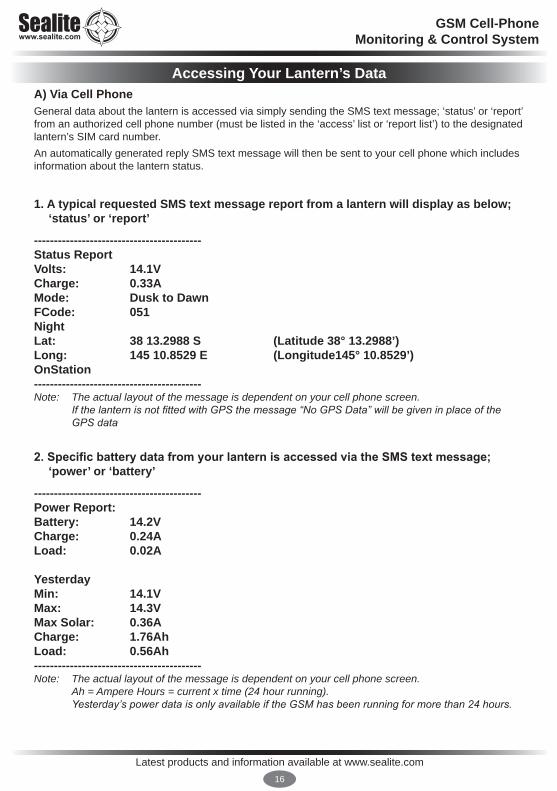
Accessing Your Lantern’s DataA) Via Cell PhoneGeneral data about the lantern is accessed via simply sending the SMS text message; ‘status’ or ‘report’ from an authorized cell phone number (must be listed in the ‘access’ list or ‘report list’) to the designated lantern’s SIM card number. An automatically generated reply SMS text message will then be sent to your cell phone which includes information about the lantern status.
1. A typical requested SMS text message report from a lantern will display as below; ‘status’ or ‘report’
------------------------------------------Status ReportVolts: 14.1VCharge: 0.33AMode: Dusk to DawnFCode: 051NightLat: 38 13.2988 S (Latitude 38° 13.2988’)Long: 145 10.8529 E (Longitude145° 10.8529’)OnStation------------------------------------------Note: The actual layout of the message is dependent on your cell phone screen. IfthelanternisnotfittedwithGPSthemessage“NoGPSData”willbegiveninplaceofthe
GPSdata
2. Specific battery data from your lantern is accessed via the SMS text message; ‘power’ or ‘battery’
------------------------------------------Power Report:Battery: 14.2VCharge: 0.24ALoad: 0.02A
YesterdayMin: 14.1VMax: 14.3VMax Solar: 0.36ACharge: 1.76AhLoad: 0.56Ah------------------------------------------Note: The actual layout of the message is dependent on your cell phone screen. Ah = Ampere Hours = current x time (24 hour running). Yesterday’spowerdataisonlyavailableiftheGSMhasbeenrunningformorethan24hours.

Latest products and information available at www.sealite.com17
GSM Cell-PhoneMonitoring & Control System
3. A more detailed report from the lantern is available by sending the SMS text ‘status full’. This will result in your lantern sending 4 x SMS replies to your phone------------------------------------------Extended StatusVolts: 14.1VCharge: 0.33AMode: Dusk to DawnFCode: 051NightLat: 38 13.2988 S (Latitude 38° 13.2988’)Long: 145 10.8529 E (Longitude145° 10.8529’)OnStationProduct ID: SLLEDCTRL (Example only)Product Name: Sealite Test Sample (20 Character Limit)------------------------------------------------------------------------------------Colour: WhiteStatus Flags: 00018Temperature Sensor: OKLantern Temperature: OKIntensity: 100%Adv Op Mode: AllSync Offset: 0.0sGPS Mode Normal------------------------------------------------------------------------------------GPS Watch Circle: 200mLantern Voltage: 14.1VLantern Battery: OKGSM Voltage: 13.9VGSM Battery: OKGSM Mode: NormalGSM Carrier: Telstra------------------------------------------------------------------------------------GSM Signal: MaxTriggered Alarms: None------------------------------------------
Note: The actual layout of the message is dependent on your cell phone screen.If the lantern is not fitted with GPS the message “No GPS Data” will be given in place of the GPS dataThis message is requires 4 x Text Messages to be sent. There may be cost implications depending on your Sim Card Phone Plan.

Latest products and information available at www.sealite.com18
GSM Cell-PhoneMonitoring & Control System
The add CommandThe “add” command allows;• Cell phone numbers to be added to the ‘access’ and ‘report’ lists and;• Required alarms and autoreports to be enabled.
Only users listed in the Access List are able to use the “add” commands
Full cell phone numbers including ‘+’ and country code must be used when adding cell phone numbers to the ‘access’, ‘report’ & ‘web’ lists.
To add the cell phone number 0402123456 to the ‘report’ list the following command would be sent in an SMS text message from any cell phone number listed in the access list:“add report +61402123456”
A successful update would result in an SMS text message reply: “Report List +61402123456”
To add a low battery alarm trigger the following command would be sent in an SMS text message from an authorised cell phone:“add alarm batlo”
A successful update would result in an SMS text message reply:“Alarm Added Low BatteryNo Lantern DataNo GPS Data Web”
4. Via Sealite GSM Web PortalTo configure your GSM lantern to send daily reports or alarms to Sealite’s secure online GSM Web Portal the following messages MUST be sent via SMS text message to your lantern:“add alarm web” Then send the SMS text message:“add autoreport web”

Latest products and information available at www.sealite.com19
GSM Cell-PhoneMonitoring & Control System
Command Parameter Function
Example Command
Format
add
access Adds additional cell phone number(s) to the permitted access list. More than one cell phone number can be included in the SMS by separating each number with a “comma” character. The same cell phone number may also be programmed into the “report” list. The access list can contain a maximum of 16 cell phone numbers.
add access +61402123456
or/
add access +61402123456, +61402654321
report Adds additional cell phone number(s) to the permitted report list. More than one cell phone number can be included in the SMS by separating each number with a “comma” character. The same cell phone number may also be programmed into the “access” list. The report list can contain a maximum of 16 cell phone numbers.
add report +61402123456
or/
add report +61402123456, +61402654321
alarm / autoreport
Adds the required alarm or autoreport functions that will report to the cell phones in the report list.More than one alarm can be included in the SMS. Separate each alarm condition with a “space” character. Possible alarms are:batlo, nodata, daily, nogps, offstation, web, power Possible autoreports are:status, daily, battery, power, web
add alarm batlo
or/
add alarm batlo, nogps
or/
add autoreport status
All cell phone numbers must be presented in international format – ie/ In Australia ‘0402123456’ becomes ‘+61402123456’. In the United Kingdom, ‘07791234567’ becomes ‘+447791234567’.The maximum phone number can be 15 digits long, if you require more than 15 digits please contact Sealite.

Latest products and information available at www.sealite.com20
GSM Cell-PhoneMonitoring & Control System
The list CommandThe “list” command allows the operator to view:• Cell phone numbers listed in the ‘access’, ‘report’ and ‘web’ lists and;• List enabled alarms and autoreports programmed into the lantern.
Only users listed in the Access List are able to use the “list” commands
To determine the cell phone number entries in the ‘report’ list the following SMS text message command would be sent:“list report”
The GSM Monitoring and Control System would SMS text message a response containing the contents of this list:“Report List: +61402123456, +61402654321”
To determine the ‘alarm’ list the following SMS text message command would be sent:“list alarm”
The GSM Monitoring and Control System would SMS text message a response containing the contents of this list:“current alarm list: nodata, temphi, nogps, nopps, batlo”
Command Parameter Function
Example Command
Format
list
access Requests a list of the current cell phone numbers in the access list. An SMS is returned showing the current access list.
list access
report Requests a list of the current cell phone numbers in the report list. An SMS is returned showing the current report list.
list report
web Requests a list of the current Sealite web gateway phone number. An SMS is returned showing the current report list.
list web
alarm / autoreport
Requests a list of the current alarms and autoreports programmed into the alarm list. An SMS is returned showing the current alarm list.
list alarmor/
list autoreport
All telephone numbers must be presented in international format – ie/ In Australia ‘0402123456’ becomes ‘+61402123456’. In the United Kingdom, ‘07791234567’ becomes ‘+447791234567’.

Latest products and information available at www.sealite.com21
GSM Cell-PhoneMonitoring & Control System
The delete CommandThe “delete” command operates in the same way as the “add” command. The difference is the “delete” command will also accept the keyword “all”. This allows the list to be cleared in a single SMS text message.
Only users listed in the Access List are able to use the “delete” commands
To remove the cell phone number 0402123456 from the report list the following command would be sent:“delete report +61402123456”
A successful deletion would result in an SMS text message reply:“Report List Empty”
When the report list is “empty”, this means that there are no cell phone numbers in the ‘report’ list, therefore disabling the automatic alarm function.
To remove an alarm from the alarm list the following command would be sent:“delete alarm batlo”
A successful deletion would result in an SMS text message reply:“Alarm DeletedNo Lantern DataNo GPS Data”
Command Parameter Function
Example Command
Format
delete
access Deletes the requested cell phone number from the permitted access list.
delete access +61402123456
report Deletes the requested cell phone number from the permitted report list.
delete report +61402123456
web Deletes the requested cell phone number from the permitted web list.
delete web +61418569242
alarm / autoreport
Deletes the requested alarm or autoreport from the current alarm list.
delete alarm batlo
All telephone numbers must be presented in international format – ie/ In Australia ‘0402123456’ becomes ‘+61402123456’. In the United Kingdom, ‘07791234567’ becomes ‘+447791234567’.
Latest products and information available at www.sealite.com22
GSM Cell-PhoneMonitoring & Control System
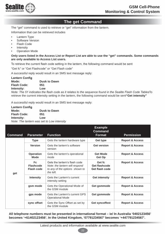
The get CommandThe “get” command is used to retrieve or “get” information from the lantern.Information that can be retrieved includes• Lantern Type• Software Version• Flash Code• Intensity• Operation ModeOnly users listed in the Access List or Report List are able to use the “get” commands. Some commands are only available to Access List users.To retrieve the current flash code setting in the lantern, the following command would be sent“Get fc” or “Get Flashcode” or “Get Flash code”A successful reply would result in an SMS text message reply:Lantern ConfigMode: Dusk to DawnFlash Code: 051Intensity: LowNote:The51indicatestheflashcodeasitrelatestothesequencefoundintheSealiteFlashCodeTablesTo retrieve the current intensity setting in the lantern, the following command would be sent“Get intensity”
A successful reply would result in an SMS text message reply:Lantern ConfigMode: Dusk to DawnFlash Code: 051Intensity: LowNote: The lantern was set to Low intensity
Command Parameter Function
Example Command
Format Permission
get
Type Gets the lantern hardware type Get type Report & Access
Version Gets the lantern’s software version
Get version Report & Access
Operation Mode
Gets the lantern’s operational mode
Get ModeGet Op
Report & Access
Fc Flashcode Flash code
Gets the lantern’s flash codeNote: the lantern will respond to any of the options shown to the left.
Get fc Get flashcode Get flash code
Report & Access
Intensity Gets the Lantern’s current intensity setting
Get intensity Report & Access
gsm mode Gets the Operational Mode of the GSM module
Get gsmmode Report & Access
gps mode Gets the Lantern’s current GPS Operational Mode
Get gsmmode Report & Access
sync offset Gets the Sync Offset as set by the GSM module
Get syncoffest Report & Access
All telephone numbers must be presented in international format – ie/ In Australia ‘0402123456’ becomes ‘+61402123456’. In the United Kingdom, ‘07791234567’ becomes ‘+447791234567’.
Latest products and information available at www.sealite.com23
GSM Cell-PhoneMonitoring & Control System
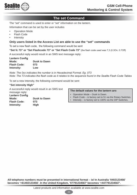
The set CommandThe “set” command is used to enter or “set” information on the lantern.Information that can be set by the user includes• Operation Mode• Flash Code• Intensity
Only users listed in the Access List are able to use the “set” commandsTo set a new flash code, the following command would be sent“Set fc 73” or “Set Flashcode 73” or “Set Flash Code 73” (the flash code used was 7,3 (0.3On, 0.7Off)
A successful reply would result in an SMS text message reply:Lantern ConfigMode: Dusk to DawnFlash Code: 073Intensity: Low
Note:The0xxindicatesthenumberisinHexadecimalFormat.Eg.073Note:The73indicatestheflashcodeasitrelatestothesequencefoundintheSealiteFlashCodeTables
To set a new intensity, the following command would be sent“Set intensity High”A successful reply would result in an SMS text message reply:Lantern ConfigMode: Dusk to DawnFlash Code: 073Intensity: High
All telephone numbers must be presented in international format – ie/ In Australia ‘0402123456’ becomes ‘+61402123456’. In the United Kingdom, ‘07791234567’ becomes ‘+447791234567’.
The default values for the lantern are:• Operation Mode – Dusk to Dawn.• Flash Code – is factory set to 51 via the Rotary Switches. • Intensity – is factory set to 100% via the DIP Switches.

Latest products and information available at www.sealite.com24
GSM Cell-PhoneMonitoring & Control System
Command Parameter Function Example Command Format
Permission
set
Mode Sets the lantern’s operation mode. • Dusk to Dawn, on• Standby, off• Always on
Set mode Dusk to DawnSet mode Standby
Set mode Always on
Access
Fc Flashcode Flash code
Sets the lantern’s flash codeNote: the lantern will respond to any of the options shown to the left. The flash code set by this command will remain active until either a new command is received or the Rotary Switches are changed.
Set fc 51Set flashcode 51Set flash code 51
Access
Intensity Sets the Lantern’s current intensity settingIntensities that can be set are• Low• Medium• High The intensity set by this command will remain active until either a new command is received or the DIP Switches are changed.
Set intensity low Access
gsm defaults
This resets the GSM settings. It clears the Access and Report number lists and disables all alarms.
Set gsm defaults Access
gsm mode Sets the Lantern’s GSM Operational Mode. It alters the power saving strategy.
Set gsmmode slowSet gsmmode normal
Set gsmmode always on
Report & Access
gps mode Sets the Lantern’s GPS Operational Mode. It alters the power saving strategy.
Set gpsmode slowSet gpsmode normal
Set gpsmode always on
Report & Access
sync offset Sets the Lantern’s GPS Sync Offset. If two lantern’s are flashing with the same flashcode but need to be distinguished, the GSM Module can offset the Synchronisation of the lantern. The offset is 0 – 300 secs. (0.1 increments)For example if you wish to offset a lantern 1.5 seconds send the following example.
Set syncoffset 1.5 Access
All telephone numbers must be presented in international format – ie/ In Australia ‘0402123456’becomes ‘+61402123456’. In the United Kingdom, ‘07791234567’ becomes ‘+447791234567’.
GPS ModeTo reduce power consumption in your Lantern over a 24Hour period it is now possible to change the number of times the GPS module activates. The default setting is Normal. Only users on the Access List can change this setting.

Latest products and information available at www.sealite.com25
GSM Cell-PhoneMonitoring & Control System
GPS Mode
Description Example Command Format
Off The GPS is always off Set GPS mode off
Normal The GPS is turned off for 15 minutes (Night) and 30 minutes (Day) Set GPS mode normal
Fast The GPS is turned off for 5 minutes (Night) and 10 minutes (Day) Set GPS mode fast
On The GPS is always left on Set GPS mode on
GSM Mode
Battery State Module Usage
Slow
Normal (> 11.5V) On for 5 minutesOff for 55 minutes
Low (10V to 11.5V) On for 5 minutesOff for 115 minutes
Flat (<10V) On for 3 minutesOff for 235 minutes
Normal
Normal On for 5 minutesOff for 15 minutes
Low On for 5 minutesOff for 30 minutes
Flat On for 3 minutesOff for 57 minutes
Fast
Normal On for 5 minutesOff for 5 minutes
Low On for 5 minutesOff for 30 minutes
Flat On for 3 minutesOff for 57 minutes
Always On
Normal Always On
Low Always On
Flat On for 3 minutesOff for 57 minutes
GSM & GPS ModeTo reduce power consumption in your Lantern over a 24Hour period it is now possible to change the number of times the GSM module activates. The default setting is Normal
Only users on the Access List can change this setting

Latest products and information available at www.sealite.com26
GSM Cell-PhoneMonitoring & Control System
STEP 4:Accessing the Sealite GSM Web Portal
CREATE A GSM ACCOUNTAfter daily web reporting has been enabled via SMS text message command and your GSM lantern, access to historical data and graphs about individual lantern installations is available via the Sealite website.
Follow the steps below to access your lantern operational data;
1. Go to www.sealite.com on the internet,
2. Select the Technical tab,
3. Select Create a GSM Account
For lantern data to be updated daily in the Sealite GSM Web Reports, users must first send the SMS text message command “add alarm web” to the designated lantern(s).

Latest products and information available at www.sealite.com27
GSM Cell-PhoneMonitoring & Control System
2. Complete the details on the GSM System Account Creation screen including your contact details and valid Sealite GSM Product Serial Number, and click Submit
3. Check your email account for confirmed secure login details.
Successful submissions will display the message below.

Latest products and information available at www.sealite.com28
GSM Cell-PhoneMonitoring & Control System
LOG INTO YOUR GSM ACCOUNT4. Go to www.sealite.com on the internet, select the Technical tab, then select GSM Portal.
5. Complete your login details.

Latest products and information available at www.sealite.com29
GSM Cell-PhoneMonitoring & Control System
Once logged in, you will come to the GSM Dashboard page.
This page has menus you can use to navigate your way around Sealite’s GSM Web Portal where you can perform a variety of tasks such as adding or removing GSM lanterns, viewing your lantern installations on a map, view critical lantern data or request help.
You can easily return to this page at any time by selecting Dashboard in the menu on the left of the page.
GSM Dashboard

Latest products and information available at www.sealite.com30
GSM Cell-PhoneMonitoring & Control System
CONFIGURATIONThe Configuration Table menu of the GSM Dashboard enables you to do the following:
• See critical lantern data in summary table view
• Drill down on each lantern to view all data
• Add or remove GSM lanterns
• Enable & configure alarm email messaging
• Enable & configure daily email reports

Latest products and information available at www.sealite.com31
GSM Cell-PhoneMonitoring & Control System
Add GSM Lanterns
To register your lantern with Sealite’s secure online web reporting system you need to add it to your account:
1. Select Configuration Table from the GSM Dashboard or select Configuration Table in the menu on the left of the page.
2. Click on ADD+ This can be found at the bottom right of the table.
For lantern data to be updated daily in the Sealite GSM Web Reports, users must first send the SMS text message command “add alarm web” to the designated lantern(s).

Latest products and information available at www.sealite.com32
GSM Cell-PhoneMonitoring & Control System
3. The following page will appear on your screen.
4. Fill in the details of your lantern: Identify: Enter the lantern’s individual cell-phone number and identifying name. It is suggested that the name of the lantern be descriptive for easy identification.

Latest products and information available at www.sealite.com33
GSM Cell-PhoneMonitoring & Control System
5. Activate Alarm emails
Configure: ENABLE ALARM EMAILS Check this box if you wish to receive an email if this lantern triggers an alarm.
Enter the email addresses of the personnel that you wish to receive alarm messages.You can enter the email addresses of up to 2 additional recipients.If an alarm is triggered an email will be sent to these addresses.

Latest products and information available at www.sealite.com34
GSM Cell-PhoneMonitoring & Control System
5. Activate Report emails
Configure: ENABLE REPORT EMAILS Check this box if you wish to receive an email report from this lantern daily. Enter the email addresses of the personnel that you wish to receive daily reports. You can enter the email addresses of up to 2 additional recipients.
Process: Click the Submit button to register your lantern. Data for your lantern will be available approximately 24 hours from the time the lantern is put into actual service or powered up.
For lantern alarm data to be sent to the Sealite GSM Web Portal when triggered, users must first send the SMS text message command to the lantern to set up the particular alarm required.

Edit GSM Lantern Information
To modify the lanterns information:
1. Select Configuration Table from the GSM Dashboard or select Configuration Table in the menu on the left of the page.
2. Locate the lantern you wish to modify and click on EDIT (this appears to the right of the lantern).
3. Modify the lantern details and click the Submit button at the bottom of the page.

Latest products and information available at www.sealite.com36
GSM Cell-PhoneMonitoring & Control System
4. The following screen will appear to inform you that your update was processed successfully.

Remove GSM Lanterns
To remove a lantern:
1. Select Configuration Table from the GSM Dashboard or select Configuration Table in the menu on the left of the page.
2. Locate the lantern you wish to remove and click on EDIT (this appears to the right of the lantern).
3. Click the Delete button at the bottom of the page to remove the selected lantern.

Latest products and information available at www.sealite.com38
GSM Cell-PhoneMonitoring & Control System
See Critical Lantern Data in Summary View Table
This will take you to a new page with a summary listing of all your GSM lanterns registered in the system.
1. Select Configuration Table from the GSM Dashboard or select Configuration Table in the menu on the left of the page.
2. The following table summary will appear:
3. The background colour of a particular lantern will change to a red colour if an alarm condition is present.

Latest products and information available at www.sealite.com39
GSM Cell-PhoneMonitoring & Control System
Drill Down on Each Lantern to View All Data
This will take you to a new page showing detailed information for the GSM lantern selected.
1. Select Configuration Table from the GSM Dashboard or select Configuration Table in the menu on the left of the page.
2. The following table summary will appear:
3. Click the cell-phone number of the lantern you wish to view in more detail.
4. The following detailed report for the lantern will appear in a new window. Breaks in the data represent periodic absence of data transmission or removal of lantern for servicing.
Lantern with an alarm

Latest products and information available at www.sealite.com40
GSM Cell-PhoneMonitoring & Control System
5. For help viewing detailed information about Charts, Data and Email Reporting click on the ‘i’ button to the left of the screen:
Chart help
Data help
Email reporting
help

Latest products and information available at www.sealite.com41
GSM Cell-PhoneMonitoring & Control System
DEPLOYMENT MAPThe Deployment Map section of the GSM Dashboard enables you to do the following:
• See entire GSM lantern network in map view
• Click on items to see summary data
• Drill down on each lantern to view all data

Latest products and information available at www.sealite.com42
GSM Cell-PhoneMonitoring & Control System
This allows you to view the location of your GSM Lantern installations via map.
1. Select Deployment Map from the GSM Dashboard or select Deployment Map in the menu on the left of the page.
2. A map of your GSM lanterns will appear with the Sealite Logo indicating the location of your installation(s). Use the zoom in/out tool bar at the top left of the page to navigate around the map.
3. To see summary data for a specific lantern, click on the Sealite icon on the map. A call-out box appears on the map with the summary data of the lantern.
4. The Sealite Logo will be highlighted in red if an alarm condition occurs.
4. To drill down on the lantern to view all data, click on View Full Details in the call-out box and a new window will open displaying detailed information about the lantern.
Lantern with an alarm condition

Latest products and information available at www.sealite.com43
GSM Cell-PhoneMonitoring & Control System
REQUEST HELPThe Request Help menu of the GSM Dashboard enables you to submit a form to Sealite to request assistance from a Sealite GSM expert.

Latest products and information available at www.sealite.com44
GSM Cell-PhoneMonitoring & Control System
1. Select Request Help from the GSM Dashboard or select HELP!! in the menu on the left of the page.
2. The following form will appear.
3. Complete the details.
4. Click Submit

Latest products and information available at www.sealite.com45
GSM Cell-PhoneMonitoring & Control System
CHANGE PASSWORDThe Change Password menu of the GSM Dashboard enables you to change your password:

Latest products and information available at www.sealite.com46
GSM Cell-PhoneMonitoring & Control System
REMEMBER TO LOG OUT WHEN YOU HAVE FINISHED VIEWING YOUR GSM LANTERN DATA
(click “LOG OUT” at the top right of the page)
1. Select Change Password from the GSM Dashboard or select Change Password in the menu on the left of the page.
2. Complete the details.
3. Click Submit

Latest products and information available at www.sealite.com47
GSM Cell-PhoneMonitoring & Control System
Lantern Installation LocationThe lantern must be installed in a location where there is adequate GSM and if fitted GPS signal coverage from your service provider.Final GPS location of your lantern can be obtained via SMS text message once it is installed and the power is connected. Data will not be available from the GSM Monitoring and Control System for a minimum of 1 minute after the power has been connected.
GSM MONITORING AND CONTROL LANTERNS: DESIGNATED LANTERN SIM CARD NUMBERS
Lantern Name (eg. Channel Lantern 1) Installation Location
Cell phone Number (eg. +61432123456)
Master Telephone Number
(eg. +61456123456)

Latest products and information available at www.sealite.com48
GSM Cell-PhoneMonitoring & Control System
Lantern Name Contact NameCell phone Number (eg. +61432123456) Email Address
REMOTE REPORT CELL PHONE NUMBERS & EMAIL CONTACTS

Latest products and information available at www.sealite.com49
GSM Cell-PhoneMonitoring & Control System
Trouble ShootingInitial Setup The most important step in the process of setting up your GSM monitoring and control module is to ensure desired cell phone numbers are programmed into the access list. Use the list access command (see “Sending Commands” on page 20) to confirm cell phone numbers are correctly entered. Re-enter from a correctly listed cell phone the numbers required. If the initial access list number(s) are incorrectly entered, lost, or if the lantern’s cell phone number will not respond, power up the lantern and email Sealite technicians ([email protected]) the following details:• Designated Lantern SIM Card Number • Country Code • Lantern Serial Number ** **PleaseNote:Achargemaybeleviedforthisservice
Web Reporting If no data is available from your secure web login after following the outlined procedure: • Send the SMS text message “list alarm” to check that the alarm to the web has is enabled• If the alarm has been enabled, then re-send the SMS text message “add web +61418569242” to
ensure the gateway is open.

Latest products and information available at www.sealite.com50
GSM Cell-PhoneMonitoring & Control System
Problem RemedyLantern will not activate. • Ensure lantern is in darkness.
• Wait at least 60 seconds for the program to initialise in darkness.• Ensure switch setting is on a valid code (not unused flash code).• Ensure battery terminals are properly connected.• Ensure battery voltage is above 12volts.
Timing codes will not change. • Turn rotary switches several times to ensure contacts are clear.
Lantern will not operate for the entire night.
• Expose lantern to direct sunlight and monitor operation for several days. Sealite products typically require 3 hours of direct sunlight per day to retain full autonomy. From a discharged state, the lantern may require several days of operational conditions to ‘cycle’ up to full autonomy.
• Reducing the light output intensity or duty cycle (flash code) will reduce current draw on the battery.
• Ensure solar module is clean and not covered by shading during the day.• Reduce the GSM Mode to Slow. This will reduce current draw on the battery.
My lantern won’t respond to the 1st message I send on setup.
• Ensure SIM card is active, has credit, and is fitted correctly.• Ensure there is no PASSWORD on the SIM card account and the SIM Card is
unlocked.
My SMS reports are sometimes showing N/A or reports that “no data” has been received.
• This indicates that the GPS or battery charge at night is not available. Otherwise the lantern may have failed therefore responding with a reading of “N/A” (not available). Contact Sealite for further help.
When I send an SMS there is no SMS response from the lantern within 5-20 minutes.
• The cell phone monitoring system is reliant on cell phone coverage and gateway traffic, and may suffer from occasional drop outs, or the lantern may be located in a marginal GSM coverage area (check with your local network provider for coverage details). One or all of these parameters affect the performance of your monitoring system.
• The GSM implements a sleep cycle to save power. Under normal conditions the GSM will be put to sleep for 15 minutes at a time.
• Your phone is not listed in either the Report or Access list. If you try to send a Get or Set command, the Lantern will reply with the following message “Unknown Command”
When I send an SMS there is no response.
• Please make sure you are listed on the Access or Report List.• Check the number you are ringing from is listed in the access list or the
report list.• Try sending the SMS from a different phone using a different network.
Lantern response is “Unknown Command”
• The GSM has not recognised the command. Refer to Command section of this manual to ensure a valid texted message has been sent to the GSM.
• The GSM allows up to 10 occurrences of this response in any 24 hour period. Additional invalid commands will not trigger a response until the commencement of the next 24hr period.
• Please make sure you are listed on the Access or Report List.
My lantern does not appear on the web portal
• Send the SMS text message “list alarm” to check that the alarm to the web has is enabled
• If the alarm has been enabled, then re-send the SMS text message “add web +61418569242” to ensure the gateway is open
Trouble Shooting Table

Latest products and information available at www.sealite.com51
GSM Cell-PhoneMonitoring & Control System
Lantern Board Indicator / Status LED’sThere are two status LED’s located on the master circuit board.The red status LED is used to indicate the health of the lantern’s power system, eg battery voltage. The Yellow status LED is used to indicate the operational status of the lantern. These indicator LEDs can be viewed through the side of the base of the lantern.
Yellow LED Lantern Status Lantern Comment
OFF Normal OFF Lantern is in Daylight and in Dusk till Dawn mode or in Standby Mode
Flashing ON 0.15 secondsOFF 0.15 seconds
Normal OFF Light is activating and will turn on after detecting 30 seconds of continuous darkness.
Flashing2 x quick flashes every 2 seconds (Heartbeat)
Normal ON Lantern is in Normal operating condition. It is not connected to any GPS synchronisation.
Flashing ON 1.5 secondsOFF 1.5 seconds
Normal ON Normal operating condition. Lantern is synchronised to GPS-enabled lanterns.
Flashing1 x quick flashevery 2 seconds
Normal ON Lantern is ‘re-syncing’ with GPS. The lantern re-sync’s with the GPS every 15 minutes.
Flashing2 x quick flashes every 11 seconds
Normal ON Lantern is a Hard Wire Synchronisation Slave.
Red LED Lantern Status Lantern CommentOFF Normal Normal Battery VoltageFlashing once every 1.6 seconds
Battery Voltage is 12 – 12.5V Battery Voltage is between 12 – 12.5V
Flashing twice every 2 seconds
Battery Voltage is 11.5 – 12V Battery Voltage is between 11.5 – 12V
Flashing 3 x times every 2 seconds
Battery Voltage is 10.5 – 11.5V Battery Voltage is between 10.5 – 11.5V
Flashing 4 x times every 2.5 seconds
Battery Voltage is 10.0 – 10.5V Battery Voltage is between 10.0 – 10.5V
Flashing 5 x times every 3 seconds
Battery Voltage is less than
10.0VBattery Voltage is at less than 10.0V
Fixed-on Flat Battery (<10V) OFF
Flat Battery cut-off is now operational and the lantern will be off. Battery must receive charge (above 12V) and lantern must see daylight for at least 1 minute before resuming normal operation.
Flashing ON 1.5 secondsOFF 1.5 seconds
Battery Voltage is above 13.5V
Battery Voltage is above 13.5V. this may indicate a problem with the solar regulator.

Latest products and information available at www.sealite.com52
GSM Cell-PhoneMonitoring & Control System
Phone Module Indicator / Status LED’sThe GSM board is fitted with a number of Indicator LED’s. Use the diagram below to help determine operational status.
ToviewIndicatorLED’sfollowthestepsshownoninthe“InstallingaSIMCard”sectionofthismanual
Antenna Connection Point
Yellow LED
GSM Module
SIM Card Holder
Red LED
Green LED

Latest products and information available at www.sealite.com53
GSM Cell-PhoneMonitoring & Control System
LED Combinations Condition
Green LED Red LED Yellow LED The initial setup process takes approximately 1 minute. The below sequence is what you
will see after power is connected.
Slow Off Off The GSM module is in the process of being setup. (Approx. 30Seconds)
1 Quick 1 Quick Off The GSM module setup is complete. The SIM card is being setup and is now ready for operation. (Approx. 15 seconds) GSM Signal is not ready
1 Quick 1 Quick Slow The GSM module setup is complete. The SIM card is ready for operation. The network signal is being calculated by the GSM Module (Approx. 5 seconds)
1 Quick 1 Quick 1 Quick (Low) 2 Quick (OK) 3 Quick (Good) 4 Quick (Max)
The GSM module setup is complete. The SIM card is ready for operation. The network is ready. The yellow status LED indicates signal strength.
2 Quick Off Off GSM Module setup is complete and the GSM module is asleep. The GSM Module enters Sleep Mode after 5 minutes of operation. It wakes up after 15 minutes in Normal Mode.
During the initial setup process, faults may be found with the SIM Card, Network Signal or GSM Module itself. The table below shows these faults and how the Status LED’s will
indicate a fault..
Steady Off Off The setup of the GSM module has failed. Check that the module is present. Reset the unit and try again. Note: The unit will automatically reset within 1 hour and try again.
Slow Steady Steady
The GSM module is in the process of being setup. The SIM card has failed. These lights will flash for 10 seconds before the unit enters Sleep Mode. Check that the SIM card is present and inserted correctly. Try cleaning the contacts in the SIM Card Holder and cleaning the SIM Card to fix.
1 Quick 1 Quick Steady
The GSM module setup is complete. The SIM card is ready for operation. The signal is not detectable. Check that the antenna is present and connected to the GSM module.
1 Quick 1 Quick Slow The GSM module setup is complete. The SIM card is ready for operation. The network is NOT ready.

Latest products and information available at www.sealite.com54
GSM Cell-PhoneMonitoring & Control System
AppendixWiring Diagrams
GSM Stand Alone using a Sun Saver-10L Solar Regulator
Latest products and information available at www.sealite.com55
GSM Cell-PhoneMonitoring & Control System
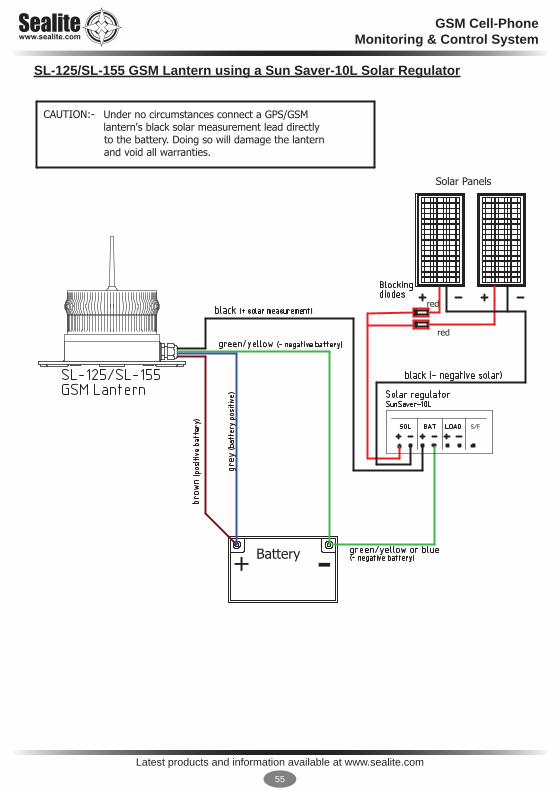
SL-125/SL-155 GSM Lantern using a Sun Saver-10L Solar Regulator

Latest products and information available at www.sealite.com56
GSM Cell-PhoneMonitoring & Control System
SL-125/SL-155 GSM Lantern using a Sealite-REG-10 Solar Regulator

Latest products and information available at www.sealite.com57
GSM Cell-PhoneMonitoring & Control System
Activating the WarrantyUpon purchase, the Sealite Pty Ltd warranty must be activated for recognition of future claims. To do this you need to register on-line. Please complete the Online Registration Form at:www.sealite.comSealite Pty Ltd will repair or replace your LED light in the event of electronic failure for a period of up to three years from the date of purchase, as per the terms & conditions below.Sealite Pty Ltd will repair or replace any ancillary or accessory products in the event of failure for a period of up to one year from the date of purchase, as per the terms & conditions below.The unit(s) must be returned to Sealite freight prepaid.Warranty Terms 1. Sealite Pty Ltd warrants that any Sealite marine products fitted with telemetry equipment including but
not limited to AIS, GSM, GPS or RF (“Telemetry Products”) will be free from defective materials and workmanship under normal and intended use, subject to the conditions hereinafter set forth, for a period of twelve (12) months from the date of purchase by the original purchaser.
2. Sealite Pty Ltd warrants that any BargeSafe™ Series of LED barge light products (“BargeSafe™ Products”) will be free from defective materials and workmanship under normal and intended use, subject to the conditions hereinafter set forth, for a period of twelve (12) months from the date of purchase by the original purchaser.
3. Sealite Pty Ltd warrants that any LED area lighting products (“Area Lighting Products”) but not including sign lighting products will be free from defective materials and workmanship under normal and intended use, subject to the conditions hereinafter set forth, for a period of twelve (12) months from the date of purchase by the original purchaser.
4. Sealite Pty Ltd warrants that any ancillary products and accessories, not mentioned in other clauses in this section, will be free from defective materials and workmanship under normal and intended use, subject to the conditions hereinafter set forth, for a period of twelve (12) months from the date of purchase by the original purchaser.
5. Sealite Pty Ltd warrants that any LED sign lighting products (“Sign Lighting Products”) will be free from defective materials and workmanship under normal and intended use, subject to the conditions hereinafter set forth, for a period of three (3) years from the date of purchase by the original purchaser.
6. Sealite Pty Ltd warrants that any Sealite marine lighting products other than the Telemetry Products, BargeSafe™ Products, and Area Lighting Products (“Sealite Products”) will be free from defective materials and workmanship under normal and intended use, subject to the conditions hereinafter set forth, for a period of three (3) years from the date of purchase by the original purchaser.
7. Sealite Pty Ltd will repair or replace, at Sealite’s sole discretion, any Telemetry Products, BargeSafe™ Products, Area Lighting Products or Sealite Products found to be defective in material and workmanship in the relevant warranty period so long as the Warranty Conditions (set out below) are satisfied.
8. If any Telemetry Products, BargeSafe™ Products, Area Lighting Products or Sealite Products are fitted with a rechargeable battery, Sealite Pty Ltd warrants the battery will be free from defect for a period of one (1) year when used within original manufacturer’s specifications and instructions.
9. Buoy products are covered by a separate ‘Sealite Buoy Warranty’.
Warranty ConditionsThis Warranty is subject to the following conditions and limitations; 1. The warranty is applicable to lanterns manufactured from 1/1/2009.2. The warranty is void and inapplicable if:
a. the product has been used or handled other than in accordance with the instructions in the owner’s manual and any other information or instructions provided to the customer by Sealite;
b. the product has been deliberately abused, or misused, damaged by accident or neglect or in being transported; or
c. the defect is due to the product being repaired or tampered with by anyone other than Sealite or
Sealite LED Light Warranty V2.2

Latest products and information available at www.sealite.com58
GSM Cell-PhoneMonitoring & Control System
Information in this manual is subject to change without notice and does not represent a commitment on the part of the vendor. Sealite products are subject to certain Australian and worldwide patent applications.
authorised Sealite repair personnel. 3. The customer must give Sealite Pty Ltd notice of any defect with the product within 30 days of the
customer becoming aware of the defect. 4. Rechargeable batteries have a limited number of charge cycles and may eventually need to be replaced.
Typical battery replacement period is 3-4 years. Long term exposure to high temperatures will shorten the battery life. Batteries used or stored in a manner inconsistent with the manufacturer’s specifications and instructions shall not be covered by this warranty.
5. No modifications to the original specifications determined by Sealite shall be made without written approval of Sealite Pty Ltd.
6. Sealite lights can be fitted with 3rd party power supplies and accessories but are covered by the 3rd party warranty terms and conditions.
7. The product must be packed and returned to Sealite Pty Ltd by the customer at his or her sole expense. Sealite Pty Ltd will pay return freight of its choice. A returned product must be accompanied by a written description of the defect and a photocopy of the original purchase receipt. This receipt must clearly list model and serial number, the date of purchase, the name and address of the purchaser and authorised dealer and the price paid by the purchaser. On receipt of the product, Sealite Pty Ltd will assess the product and advise the customer as to whether the claimed defect is covered by this warranty.
8. Sealite Pty Ltd reserves the right to modify the design of any product without obligation to purchasers of previously manufactured products and to change the prices or specifications of any product without notice or obligation to any person.
9. Input voltage shall not exceed those recommended for the product.10. Warranty does not cover damage caused by the incorrect replacement of battery in solar lantern models.11. This warranty does not cover any damage or defect caused to any product as a result of water flooding or
any other acts of nature.12. There are no representations or warranties of any kind by Sealite or any other person who is an agent,
employee, or other representative or affiliate of Sealite, express or implied, with respect to condition of performance of any product, their merchantability, or fitness for a particular purpose, or with respect to any other matter relating to any products.
Limitation of LiabilityTo the extent permitted by acts and regulations applicable in the country of manufacture, the liability of Sealite Pty Ltd under this Warranty will be, at the option of Sealite Pty Ltd, limited to either the replacement or repair of any defective product covered by this Warranty. Sealite will not be liable to Buyer for consequential damages resulting from any defect or deficiencies.
Limited to Original Purchaser This Warranty is for the sole benefit of the original purchaser of the covered product and shall not extend to any subsequent purchaser of the product.
MiscellaneousApart from the specific warranties provided under this warranty, all other express or implied warranties relating to the above product is hereby excluded to the fullest extent allowable under law. The warranty does not extend to any lost profits, loss of good will or any indirect, incidental or consequential costs or damages or losses incurred by the purchaser as a result of any defect with the covered product.
WarrantorSealite Pty Ltd has authorised distribution in many countries of the world. In each country, the authorised importing distributor has accepted the responsibility for warranty of products sold by distributor. Warranty service should normally be obtained from the importing distributor from whom you purchased your product. In the event of service required beyond the capability of the importer, Sealite Pty Ltd will fulfil the conditions of the warranty. Such product must be returned at the owner’s expense to the Sealite Pty Ltd factory, together with a photocopy of the bill of sale for that product, a detailed description of the problem, and any information necessary for return shipment.

Latest products and information available at www.sealite.com59
GSM Cell-PhoneMonitoring & Control System
Other Sealite Products Available
Marine Lanterns (1–19NM)
Bridge & Barge Lights
Area Lighting
Monitoring & Control Systems
Marine Buoys(up to 3mt in diameter)
Mooring Systems & Accessories
Sealite United Kingdom LtdUKt: +44 (0) 1502 588026
Sealite Asia Pte LtdSingapore
Sealite USA LLCUSA
t: +65 6829 2243 t: +1 (603) 737 1311
Sealite Pty LtdAustraliat: +61 (0)3 5977 6128
We believe technology improves navigation™ [email protected]