graphic communication @ st aidans high sectional views
TRANSCRIPT
graphic communication @ st aidans high
SECTIONAL VIEWS
graphic communication @ st aidans high
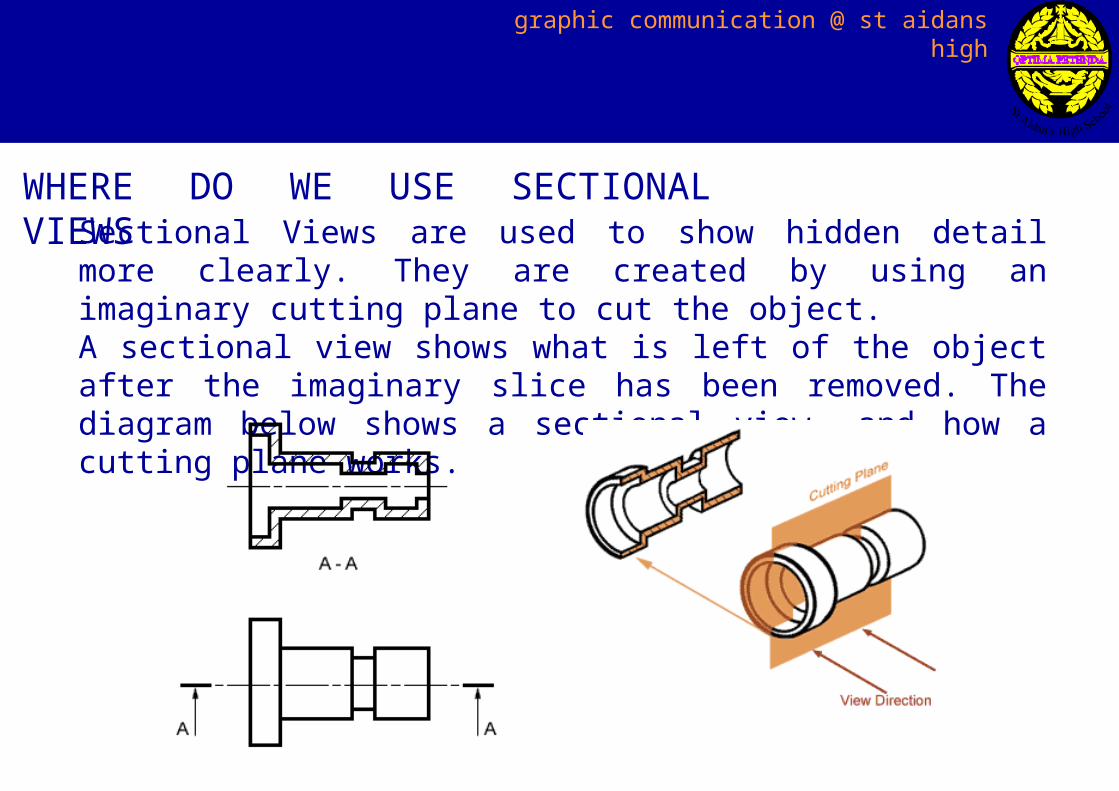
Sectional Views are used to show hidden detail more clearly. They are created by using an imaginary cutting plane to cut the object.A sectional view shows what is left of the object after the imaginary slice has been removed. The diagram below shows a sectional view, and how a cutting plane works.
WHERE DO WE USE SECTIONAL VIEWS
graphic communication @ st aidans high
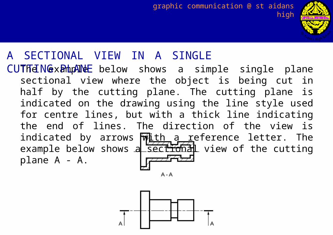
The example below shows a simple single plane sectional view where the object is being cut in half by the cutting plane. The cutting plane is indicated on the drawing using the line style used for centre lines, but with a thick line indicating the end of lines. The direction of the view is indicated by arrows with a reference letter. The example below shows a sectional view of the cutting plane A - A.
A SECTIONAL VIEW IN A SINGLE CUTTING PLANE
graphic communication @ st aidans high
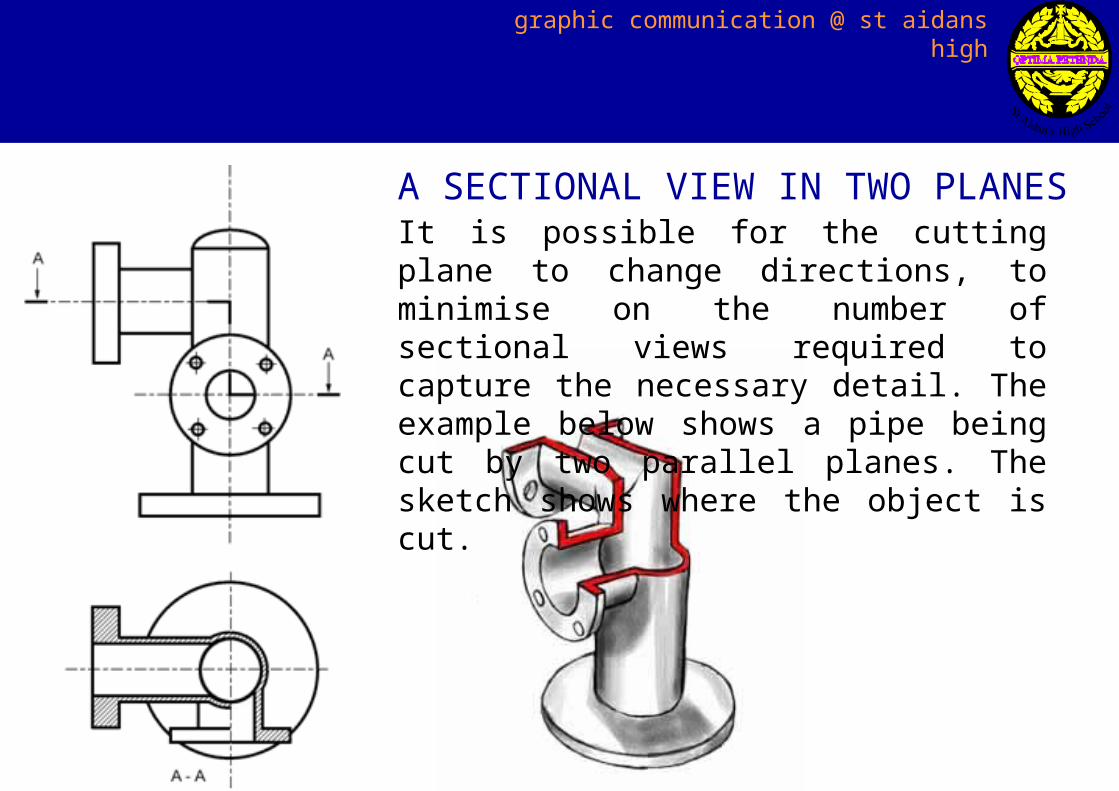
It is possible for the cutting plane to change directions, to minimise on the number of sectional views required to capture the necessary detail. The example below shows a pipe being cut by two parallel planes. The sketch shows where the object is cut.
A SECTIONAL VIEW IN TWO PLANES
graphic communication @ st aidans high
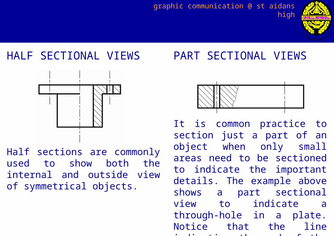
Half sections are commonly used to show both the internal and outside view of symmetrical objects.
HALF SECTIONAL VIEWS
It is common practice to section just a part of an object when only small areas need to be sectioned to indicate the important details. The example above shows a part sectional view to indicate a through-hole in a plate. Notice that the line indicating the end of the section is a thin continuous line.
PART SECTIONAL VIEWS
graphic communication @ st aidans high
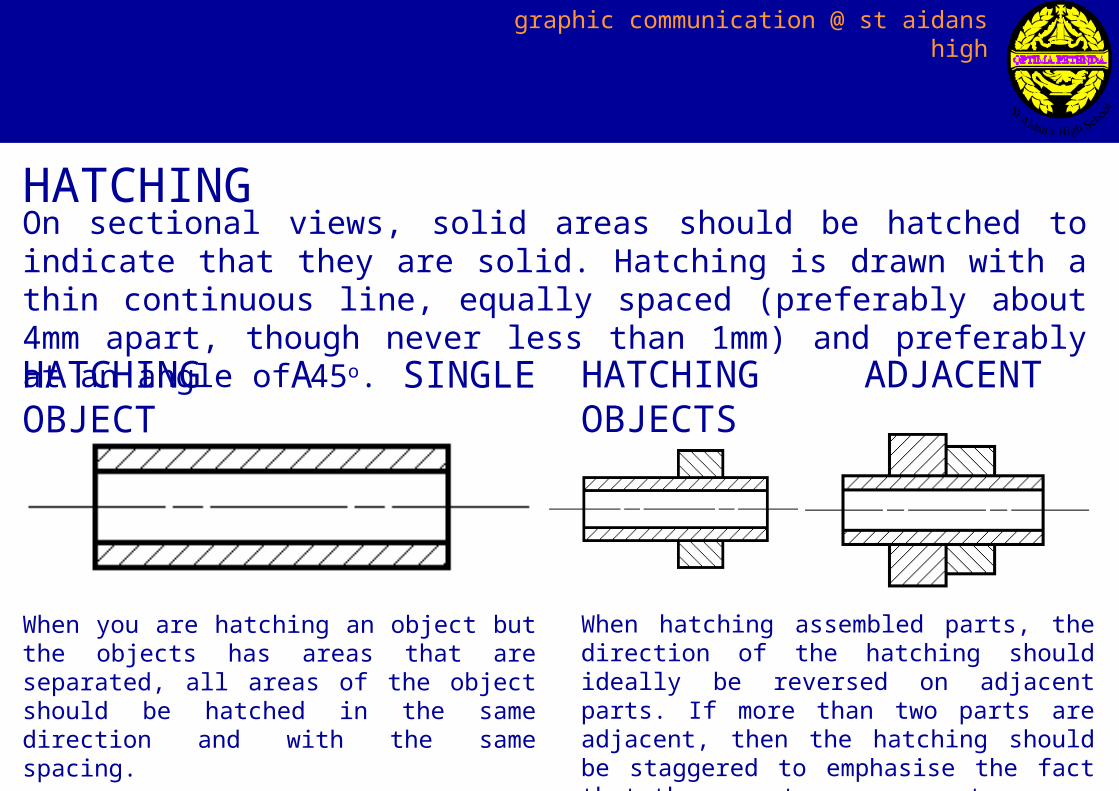
On sectional views, solid areas should be hatched to indicate that they are solid. Hatching is drawn with a thin continuous line, equally spaced (preferably about 4mm apart, though never less than 1mm) and preferably at an angle of 45o.
HATCHING
HATCHING A SINGLE OBJECT
When you are hatching an object but the objects has areas that are separated, all areas of the object should be hatched in the same direction and with the same spacing.
HATCHING ADJACENT OBJECTS
When hatching assembled parts, the direction of the hatching should ideally be reversed on adjacent parts. If more than two parts are adjacent, then the hatching should be staggered to emphasise the fact that these parts are separate.

graphic communication @ st aidans high
When hatching large areas in order to aid readabilty, the hatching can be limited to the area near the edges of the part.
HATCHING LARGE AREAS
graphic communication @ st aidans high
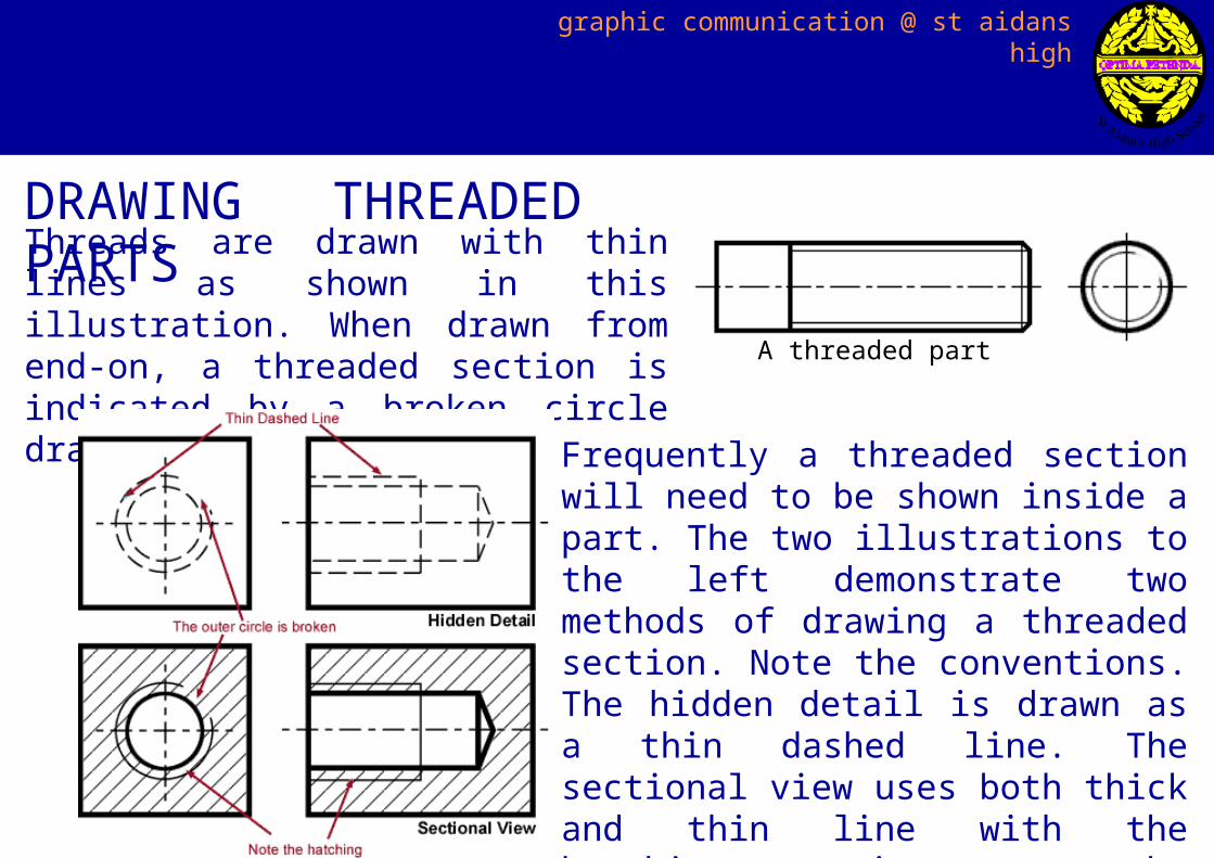
Threads are drawn with thin lines as shown in this illustration. When drawn from end-on, a threaded section is indicated by a broken circle drawn using a thin line.
DRAWING THREADED PARTS
Frequently a threaded section will need to be shown inside a part. The two illustrations to the left demonstrate two methods of drawing a threaded section. Note the conventions. The hidden detail is drawn as a thin dashed line. The sectional view uses both thick and thin line with the hatching carrying on to the very edges of the object.
A threaded part
graphic communication @ st aidans high
SECTIONAL VIEWS
finished
back to menu