graduation report
TRANSCRIPT


First, I would like to express my gratitude to Mr. Samy ACHOUR who gave me the
opportunity to tackle such a subject and to perform my internship within Integration
Objects.
I would like also to express my gratitude to my supervisors Ms. Imen MAJED and
Mr Montasser BEN OUHIDA for their precious support, guidance and advice throughout
the whole internship.
My sincere appreciation and gratitude go to my supervisor Mrs. Ghada GASMI for
her help, patience and assistance all along the phases of our project.
Furthermore, I would like to acknowledge the members of the jury who honored
me by accepting to attend the academic defense of this modest work.
Last but not least, I would like to express my sincere gratitude to all those who
contributed in my academic education particularly the professors of the National
Institute of Applied Sciences and Technology.
Acknowledgment

i
GENERAL INTRODUCTION .................................................................................................... 1
CHAPTER 1: PROJECT CONTEXT .......................................................................................... 3
Introduction ............................................................................................................................................................................4
1. Hosting organization: Integration Objects .......................................................................................................4
1.1 Company Overview ................................................................................................................................................. 4
1.2 Services....................................................................................................................................................................... 5
1.3 Company Organization Chart ............................................................................................................................... 6
2. Problematic...................................................................................................................................................................7
3. Project description ....................................................................................................................................................7
4. Methodology .................................................................................................................................................................8
4.1 RUP’s 4 phases .......................................................................................................................................................... 8
4.2 RUP’s 6 best practices ............................................................................................................................................. 9
4.3 Modeling language................................................................................................................................................... 9
Conclusion................................................................................................................................................................................9
CHAPTER 2: PRELIMINARY STUDY ...................................................................................10
Introduction ......................................................................................................................................................................... 11
1. State of the art: Code generation ....................................................................................................................... 11
Code generation introduction ............................................................................................................................11 1.1
Code generation benefits .....................................................................................................................................12 1.2
Code generation approaches ..............................................................................................................................13 1.3
Code generation: Template based approach ..................................................................................................15 1.4
1.4.1 Template based approach concept.........................................................................................................15
1.4.2 Code generation process ...........................................................................................................................17
2. Study of existing products .................................................................................................................................... 20
2.1 CodeO nTime............................................................................................................................................................20
2.2 Iron Speed................................................................................................................................................................20

ii
2.3 CodeCharge..............................................................................................................................................................21
2.4 Point by point comparison ..................................................................................................................................21
Conclusion............................................................................................................................................................................. 22
CHAPTER 3:REQUIREMENTS SPECIFICATION .................................................................23
Introduction ......................................................................................................................................................................... 24
1. The project to achieve ........................................................................................................................................... 24
Project goals ............................................................................................................................................................24 1.1
Description of project requirements ................................................................................................................25 1.2
Identification of actors .........................................................................................................................................27 1.3
System context modeling.....................................................................................................................................28 1.4
2. Capture of functional requirements ................................................................................................................ 29
2.1 Functional requirements specification ............................................................................................................29
2.2 Use case diagram ...................................................................................................................................................31
2.3 Use case organization ...........................................................................................................................................33
3. Capture of non-functional requirements ....................................................................................................... 34
3.1 Responsive web design ........................................................................................................................................34
3.2 Lightweight web elements ..................................................................................................................................35
3.3 Interactivity .............................................................................................................................................................35
Conclusion............................................................................................................................................................................. 35
CHAPTER 4: ANALYSIS & DESIGN ......................................................................................36
Introduction ......................................................................................................................................................................... 37
1 Analysis ....................................................................................................................................................................... 37
“Build web page” use case ..............................................................................................................................................37
2 Design........................................................................................................................................................................... 40
2.1 Generated web application design ....................................................................................................................40
2.1.1 Limits of ASP .NET web forms solutions ...............................................................................................41
2.1.2 What is AJAX? ...............................................................................................................................................41
2.1.3 AJAX architecture ........................................................................................................................................42
2.1.4 Generated web application design .........................................................................................................43
2.2 System global design.............................................................................................................................................44
2.3 Graphical designer module .................................................................................................................................45

iii
2.3.1 Graphical designer global architecture .................................................................................................45
2.3.2 Graphical designer package diagram .....................................................................................................47
2.3.3 Graphical designer business package ....................................................................................................48
2.3.4 The Graphical Designer UI package........................................................................................................55
2.3.5 Graphical designer DAL package ............................................................................................................58
Conclusion............................................................................................................................................................................. 58
CHAPTER 5: IMPLEMENTATION & TEST ..........................................................................59
Introduction ......................................................................................................................................................................... 60
1 Development environment .................................................................................................................................. 60
Used software and tools .......................................................................................................................................60 1.1
Used technologies ..................................................................................................................................................61 1.2
Used programming languages ............................................................................................................................62 1.3
2 Realization ................................................................................................................................................................. 64
2.1 Code generator module........................................................................................................................................64
2.2 Graphical designer module .................................................................................................................................68
2.3 Scenario for creating a web application ..........................................................................................................71
3.3.1 Setting page layouts....................................................................................................................................72
3.3.2 Adding web el ements .................................................................................................................................74
3.3.3 Configuring web elements ........................................................................................................................76
3.3.4 Build web solution ......................................................................................................................................78
3 Test & Validation ..................................................................................................................................................... 81
4.1 Generated code.......................................................................................................................................................81
4.2 Responsive design validation .............................................................................................................................82
Conclusion............................................................................................................................................................................. 86
GENERAL CONCLUSION ........................................................................................................87
BIBLIOGRAPHY ......................................................................................................................89
APPENDIX A: TEMPLATES’ DESCRIPTION ........................................................................91
APPENDIX B: GENERATED WEB ELEMENTS ....................................................................93

iv
Figure 1: Integration Objects' services ............................................................................................................... 5
Figure 2: Organization Chart of IO......................................................................................................................... 6
Figure 3: Code generation concept [5]............................................................................................................. 12
Figure 4: Template based generator ................................................................................................................. 16
Figure 5: Code generation process [4] ............................................................................................................. 18
Figure 6: Cyclical code generation process [4] ........................................................................................... 19
Figure 7: Generated web application design................................................................................................ 26
Figure 8: General Principle of “IO Graphical Designer” ......................................................................... 26
Figure 9: System context diagram ...................................................................................................................... 28
Figure 10: Use case diagram .................................................................................................................................. 32
Figure 11: Use case package diagram............................................................................................................... 34
Figure 12: AJAX architecture.................................................................................................................................. 42
Figure 13: Generated web application design............................................................................................. 43
Figure 14: Global design ........................................................................................................................................... 44
Figure 15: Graphical designer global architecture ................................................................................... 46
Figure 16: Graphical designer package diagram ....................................................................................... 47
Figure 17: Graphical designer business layer ............................................................................................. 48
Figure 18: htmlElements' package class diagram..................................................................................... 50
Figure 19: chart elements' package class diagram................................................................................... 52
Figure 20: WebPages' package class diagram ............................................................................................. 54
Figure 21: Graphical Designer.UI package..................................................................................................... 55
Figure 22: Editors class diagram ......................................................................................................................... 56
Figure 23: UserControls class diagram............................................................................................................ 57
Figure 24: DAL class diagram ................................................................................................................................ 58
Figure 25: Code generator engine ...................................................................................................................... 64
Figure 26: Gauge template ...................................................................................................................................... 66
Figure 27: Graphical designer overview......................................................................................................... 68
Figure 28: Web page designer............................................................................................................................... 69
Figure 29: Page's column designer .................................................................................................................... 70

v
Figure 30: Line chart editor .................................................................................................................................... 71
Figure 31: Overview page layout......................................................................................................................... 72
Figure 32: KPI page layout ...................................................................................................................................... 73
Figure 33: Cost page layout..................................................................................................................................... 74
Figure 34 First column designer of Overview web page ...................................................................... 75
Figure 35: Second column designer of Overview web page ............................................................... 75
Figure 36: Third column designer of Overview web page................................................................... 76
Figure 37: Line chart editor, chart option tab ............................................................................................. 77
Figure 38: Line chart editor, Axis option tab ............................................................................................... 77
Figure 39: KPI solution .............................................................................................................................................. 78
Figure 40: Overview web page ............................................................................................................................. 79
Figure 41: KPI web page ........................................................................................................................................... 80
Figure 42: Cost web page ......................................................................................................................................... 81
Figure 43: Large screen size................................................................................................................................... 83
Figure 44: Medium screen size ............................................................................................................................. 84
Figure 45: Small screen size ................................................................................................................................... 85

vi
Table I: Comparative table of code generation approaches [4] ....................................................... 14
Table II: Comparative table of existing products ...................................................................................... 22
Table III: Preliminary description of functional requirements ........................................................ 31
Table IV: List of use cases organized by package ...................................................................................... 33
Table V: Textual description of the "Build web page" use case ........................................................ 38
Table VI: System sequence diagram "Build web page".......................................................................... 39
Table VII: Code generator templates ................................................................................................................ 65
Table VIII: Generated web elements ................................................................................................................. 67
Table IX: Amount of generated code ................................................................................................................. 82
Table X: Templates' description .......................................................................................................................... 92
Table XI: Generated web elements (complete list) .................................................................................. 95

General Introduction
1 | P a g e
Web development without composing a single line of code is nowadays a trend in
the world of web. Offering graphical tools to create advanced websites without relying
on developers skills presents an attractive way to impress clients and thus surpass
competition.
Reduce the time and cost of software development and maintenance, better
manage the growth of new technologies, improve agility, all of this falls into the
primordial goals of software companies to optimize their productivity.
This race against time favored the massive development of the concept of code
generation that has evolved to higher phases of software development, to facilitate the
work of developers, have an optimum gain of time and as consequence improve
productivity. Application generators represent software components that automatically
produce other software components [1].
Throughout this project, our main objective is to design and implement a
graphical solution allowing users to visually create a complete web application without
the need of programming skills. We are required to generate a web solution that
responds to nowadays web demands and to provide advanced features for the graphical
designer.
In order to provide a comprehensive description of our work, this report details
the planned and the achieved work. It is structured as follows:
The first chapter entitled “Project context” introduces the hosting company :
Integration Objects. Then, it describes the project challenges and main objectives.
Finally, it presents the adopted work methodology.
The second chapter entitled “Preliminary study” defines the main concepts
related to our work. Then, it presents a comparative study of similar products
available in the market.
General Introduction

General Introduction
2 | P a g e
The third chapter entitled “Requirements specification”, details the project goals
and needs to be fulfilled at the end of our internship. Then, it refines these needs
by specifying the functional requirements and modeling the use case diagrams.
Finally, it exposes the non-functional requirements of our project.
The fourth chapter entitled “Analysis & Design” describes the behavior of our
system using the analysis model. It also exposes the global and detailed design of
our solution.
Finally, the last chapter “Implementation & Test” describes the development
environment and provides an overview of the achieved work.

Chapter 1: Project context

Chapter1 Project Context
4 | P a g e
Introduction
efore diving into the details of our work, it is essential to have an idea about
the host organization. Then, we present the problematic and a brief
description of our project and its main objectives. Finally, we introduce the development
methodology adopted during the realization of our work.
1. Hosting organization: Integration Objects
1.1 Company Overview
Integration Objects (IO) is a software development firm created in 2002. It is a
world-leading systems integrator and solutions provider for automation, plant
performance management, decision support, knowledge management, and system
connectivity for the process, power, and utilities industries around the globe [2].
IO1 specializes in delivering solutions that monitor plant and supply chain operation
performance and identify opportunities to increase profitability.
Its customers are located on five continents and include the largest industrial companies
in the world such as ExxonMobil, Unilever, Stora Enso, Saudi Aramco, Sumitomo
Chemical, Solvay, TetraPak, ENI, Chevron, etc. Integration Objects has collaborated and
partnered with esteemed IT firms such as Invensys, OSIsoft, TechEdge, Microsoft, etc.
Integration Objects has been certified ISO9001 since 2006. The certification was
renewed in 2009 (ISO 9001v2008).
Four strategies axes are established to ensure the implication of the staff in delivering a
product conform to the client’s requirement:
Full compliance with customer requirements,
Improving the efficiency of the organization,
Being at the forefront of technology and
Being consistent with international standards in the development of software
and project implementation.
1 Integration Objects
B

Chapter1 Project Context
5 | P a g e
1.2 Services
Integration Objects offers the following main services:
Systems Integration: IO is a leader in system integration and specialized in
delivering connectivity solutions between real-time systems, applications, and
devices, improving their interoperability, and enabling a scalable and
maintainable communication infrastructure.
Manufacturing Operations Management: IO implements MES solutions to help
companies measure and control activities in the production areas of
manufacturing organizations to improve performance and reach operations
excellence.
Telemetry & Instrumentation: IO provides turn-key solutions including RTUs,
radio transmission, and data integration, along with highly qualified
professionals for your system control, supervision, and maintenance.
Plant Automation: IO has decade of automation experience with expertise in
process control, industrial communication, and system integration [2].
The figure below demonstrates services offered by Integration Objects:
Figure 1: Integration Objects' services
• MES Solutions
• Connectivity solutions.
• Real-time systems
• Intelligent key performance Indicators.
•Entreprise Dashboards.
•Performance Reports
•Field Instrumentation.
•Data collection
•RTUs
•Radio Tranmission
•SCADA Telemetry &
Instrumentation
Plant Automation
Manufacturing Operations Management
Systems Integration

Chapter1 Project Context
6 | P a g e
1.3 Company Organization Chart
Integration objects team engineers are specialized in different domain expertise:
software development, automation, chemical process and quality management.
The figure below shows the organogram chart of IO:
Figure 2: Organization Chart of IO

Chapter1 Project Context
7 | P a g e
2. Problematic
Nowadays when information technologies represent one of the fastest developing
business areas, many software companies can respond to client requirements with the
same quality. Time required for project realization became the crucial factor to satisfy
clients. The problematic is how time can be reduced thus improving productivity and
surpassing competition.
This is why programmer’s time is valuable and presents a main constant in software
engineering. And as a programmer, we know that much of our handwritten code is
repetitive, ranging from creating simple constructs to more complex structures. High
productivity levels are impossible to attain via hand-coding.
In this context that IO binds the challenge today to provide a solution that takes over the
task of handwritten code or significant amount of repetitive code, leaving more time for
engineers to concentrate on interesting programming issues.
3. Project description
Application generators are being imposed as a solution for the problem which
can have an important impact on development time and engineering productivity.
Our project, titled “Graphical Designer for building intelligent web applications”, is about
designing and implementing a graphical solution to fully create and customize a web
application for .NET platform. And thus by proving nowadays web demands such as
responsive web design, interactivity and advanced web elements.
This allows IO clients to create a functional web application with no need of
programming knowledge and generate for IO development team the maximum amount
of repetitive code and the skeleton of the web solution, handling both efficiency and
productivity.

Chapter1 Project Context
8 | P a g e
4. Methodology
Conformed to the methodology followed by IO development team, we adopted
the Rational Unified Process (RUP) for the realization of our work.
The Rational Unified Process is a Software Engineering Process. It provides a disciplined
approach to assigning tasks and responsibilities within a development organization. Its
goal is to ensure the production of high-quality software that meets the needs of its end-
users, within a predictable schedule and budget [3].
4.1 RUP’s 4 phases
The Rational Unified Process breaks the software lifecycle into cycles, each one
working on a new generation of the product. Each development cycle is divided in four
consecutive phases:
Inception phase: The purpose of this phase is to describe the project objective and
description. This phase aims to collect and understand business requirements,
detail the project plan and agree upon a high level statement of work. This phase
identifies the project's primary objectives, constraints, deliverables and
acceptance criteria.
Elaboration phase: The purpose of this phase is to design the architecture of the
system. The goal is to translate requirements and specification into a technical
solution to produce Technical Design.
Construction phase: In this phase, the primary objective is to build the software.
The main focus is on the development of components and other features of the
system. This phase produces the first external release of the software.
Transition phase: This phase includes testing of the product in preparation of
release and taking care of issues like configuring, installing and usability issues.
The focus of this phase is to ensure that software is available for its end users.
The product is also checked against the quality level set in the Inception phase
[3].

Chapter1 Project Context
9 | P a g e
4.2 RUP’s 6 best practices
The Rational Unified Process describes how to effectively deploy commercially
proven approaches to software development for software development teams:
Develop software iteratively
Manage requirements
Use component-based architectures
Visually model software
Verify software quality
Control changes to software
4.3 Modeling language
As the RUP methodology is based on it, and because it is recognized as the
industry standard for excellence in object modeling, we chose UML as modeling
language for this project.
UML for Unified Modeling language unifies both object-oriented notations and concepts.
It includes a set of graphic notation techniques to create visual models of object-oriented
systems.
Conclusion
In this chapter we tried to provide a general overview of our project’s
environment by introducing the host organization, context and goals to achieve. We
have, also, described our working methodology.
In the next chapter, we will make a preliminary study on most commonly code
generation approaches and similar products existing on the market.

Chapter 2: Preliminary study

Chapter2 Preliminary study
11 | P a g e
Introduction
his chapter presents a preliminary study of our work. At first, we start by
introducing code generation concept and commonly used approaches in
order to make the adequate technical choice that fits our needs. Then, we provide a
presentation of related solutions existing on the market within a comparative study.
State of the art: Code generation 1.
Code generation revolutionizes the way developers program by outputting
massive amount of code. This section lays the foundation for understanding code
generation fundamentals. We cover the various approaches of code generators and
provide theoretical study that illustrates its process.
Code generation introduction 1.1
Code generation is a way of creating code rather than writing it line by line in an
editor. It is simply code that writes code [4].
Code generation provides the ability to write code once and reuse it many times within
and between applications. At first glance that may seem to offer more complexity than
benefit, but a great deal of what programmers write applying similar patterns over and
over.
Code generation is a projection of input data to output code, see Figure 3. The input data
belongs to a language with its own syntax and semantics, independently defined of the
code generator. A code generator translates the input data into another representation,
often a representation at a lower level of abstraction [5].
T

Chapter2 Preliminary study
12 | P a g e
Figure 3: Code generation concept [5]
Code generation benefits 1.2
Using generators has many advantages over manual coding. It significantly
reduces time required for application development. A code generator increases the
quality of source code by producing standardized code hence reducing number of syntax
errors which are common for manual coding. In addition, changing application code
requires only changes in particular templates and restarting the generator.
“Developing a generator as a highly sophisticated software component motivates
software developers and reduces monotony which would appear during manual coding
of significant amount of similar or repetitive code” [4].
Code generation provides substantial benefits for both software engineers and
managers. These benefits include:
Productivity: The obvious benefit of code generation is that can speed up the
development process and scale the work to create 3 or 3,000 line of code with the
same amount of effort.
Quality: Large volumes of handwritten code tend to have inconsistent quality
because engineers find newer or better approaches as they work. Code
generation from templates creates a consistent code base instantly, and when the
templates are changed and the generator is run, the bug fixes or coding
improvements are applied consistently throughout the code base.
Input
specification
Code
Generator Output
code

Chapter2 Preliminary study
13 | P a g e
Architectural Consistency: High level business rules are lost in the minutiae of
implementation code. Code generators use abstract definition files to specify the
design of the code to be generated. Once the skeleton of the targeted application
is generated, programmers are obliged to follow the predefined design.
Abstraction: Code generation offers a level of abstraction that separates
information about the targeted application (input specification) from the
technology behind it. Code generators present the application logic (UI logic,
business logic, etc.) in language independent definition files. This abstraction
gives a practical path to separately reuse both architecture and applications
details [4] [6].
To sum up, when working smarter than harder and using the computer to offload some
of daily work, we can have a stunning impact on productivity and quality in software
engineering projects.
Code generation approaches 1.3
Since we aim to generate web application for .NET platform, we dedicated this
section to study three most important code generation techniques in .NET, along with
the benefits and drawbacks of each other. This comparative study will let us decide
which fits the best for our project.
The approaches for code generation introduced in this section include a visitor-based
approach, a Microsoft-provided approach, and a template based approach:
Visitor-based approach: A very basic code generation approach consists in
providing some visitor mechanism to traverse the input specification and write
code to a text stream. It presents the most obvious approach that consists on
writing code that outputs code. This is the direct approach of simply opening a
stream and writing out code[4] [7].
Microsoft-provided approach: Microsoft provided approach presents the .NET
CodeDOM mechanism, which is designed specifically for generating code. The
CodeDOM provides a layer of abstraction that output code in c#, Visual Basic
.NET (VB .NET), J#, .NET programming languages[4].

Chapter2 Preliminary study
14 | P a g e
The template based approach: This approach implies writing special textual
templates, which basically are a set of rules. These rules specify the way of
generating code from some specific model. It uses XSLT templates to create any
type of text output, including .NET code, from an Extensible Markup Language
(XML) file [4] [8].
In order to choose which approach to apply, we expose a comparative table that
illustrates different code generation mechanisms presented previously:
Template based
approach
Visitor based
approach
Mic. Provided
approach
Code regeneration Yes No Yes
Multiple language
output from one
source
No
No
Yes
Benefits Outputs any type of
text code.
Uses standard
technologies,
platform
independent.
Deals with
complexities
(looping, searching,
string
manipulation, etc.).
Easy to read and
maintain.
No new
language or
way of
thinking
about code is
required.
Simple
Code output in
multiple
languages from
the same
source.
Drawbacks Requires learning
new language.
Complex
Hard to read
and maintain.
Don’t support
regeneration.
Complex
model with
tons of classes.
Very hard to
read.
Outputs code
only for .NET
languages.
Table I: Comparative table of code generation approaches [4]

Chapter2 Preliminary study
15 | P a g e
The comparative table of different code generation approaches led us to choose the
template based one for several reasons:
It generates code for every target language since we aim to take advantage of the
most up to date web technologies, not only ASP .NET.
It uses platform independence and standard technologies. This enhances the code
generator engine extensibility and scalability.
It allows regeneration and thus to improve user customization since the
application specification will be collected from user inputs.
Code generation: Template based approach 1.4
1.4.1 Template based approach concept
Templates are used to generate all kinds of text, including computer code. The
last decade, the use of templates gained a lot of popularity due to the increase of
dynamic web applications. The template based approach is known from its use for
instantiating HTML in web applications [9]. As a result of the popularity of templates in
web applications, numerous template generators are designed for instantiating HTML.
Besides generating HTML, template approach can be used for generating all kind of
unstructured text, like code.
Figure 4 shows the fours artifacts involved in a template based code generator. The
artifacts are metadata (input data), template, code generator engine and generated code.

Chapter2 Preliminary study
16 | P a g e
Figure 4: Template based generator
Template:
Since the literature does not provide a formal definition of a template an informal
operational definition provided by Parr [10] is given:
“A template is an output document with embedded actions which are evaluated
when rendering the template.”
Following this definition, a template is a text document that can contain placeholders. A
placeholder is a syntactical entity, indicating a missing piece of text. It contains some
actions, or expression, declaring how to obtain a piece of text to replace it. The
placeholder represents the non-complete part of the text code found in the metadata
specification.
Metadata:
Metadata is the information specific to the generated application that is collected from
database structure, entered manually, or retrieved from other sources [4]. For our
project, the metadata will be retrieved from the user manipulation of the graphical
designer.
Generated
code
Metadata
Generator
engine
Template

Chapter2 Preliminary study
17 | P a g e
1.4.2 Code generation process
Generating repetitive code makes the development job faster, and results will be
more precise. Precision means consistency; we are reproducing the same thing.
Accuracy means the output code is correct. Code generation can make precision, but it
alone can’t make accuracy.
For accuracy, we want a process that guides to effective output. A full-cycle development
methodology based on five steps of code generation lets creation of better applications
significantly faster.
Code generation process consists of five steps, as shown in the Figure 5.
The steps are:
Design Architecture: architecture overarches other steps. It defines how to build
templates and what metadata to collect.
Collect Metadata: once we know what to build, we need to capture the metadata
that drives the code generation process. The metadata defines details of the
application. It tailors the generated code to the specific application and
environment. Metadata literally tells the templates how to implement
themselves, so we can’t create quality code-generated systems without quality
metadata.
Build and run templates.
Handwritten code: code we write line by line in the editor. Handcrafted code isn’t
a new step in development; it just places what programmers currently doling in a
smaller and more focused context. It must be isolated from code build on
templates so that regeneration doesn’t smash over the handwritten code. One of
the key characteristics of code generation is respecting handcrafted code.
Test & integrate: Tie it together with integration and testing.

Chapter2 Preliminary study
18 | P a g e
Figure 5: Code generation process [4]
The pyramid below (Figure 5) illustrates that we need a strong architectural basis for
metadata collection. The architecture determines what metadata is required. Strong
architecture and valid metadata are the basis for accurate templates to generate code.
Handwritten code relies on generated code. Finally, we integrate and test the whole
application. Every step relies on the previous one.
These steps are not sequential, and there certainly is not a waterfall-style progression
between them. They occur in a sequence because each builds on the output of the
previous step. For example, we need to know what we are building before we build it,
and we can’t tie it all together in implementation until we have a complete system.
Test Integrate
Handwritten code
Build and Run Templates
Collect Metadata
Design Architecture
Chapter2 Preliminary study
19 | P a g e
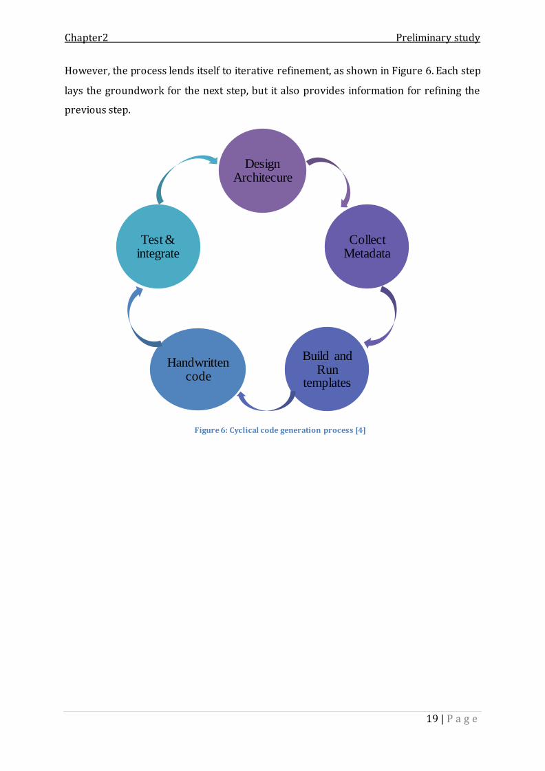
However, the process lends itself to iterative refinement, as shown in Figure 6. Each step
lays the groundwork for the next step, but it also provides information for refining the
previous step.
Figure 6: Cyclical code generation process [4]
Design Architecure
Collect Metadata
Build and Run
templates
Handwritten code
Test & integrate

Chapter2 Preliminary study
20 | P a g e
Study of existing products 2.
After giving an insight of code generation concept and approaches, we suggest to
provide an overview of similar products offering a visual utility to generate dynamic
web applications.
As graphical web designer solutions are many and various, we decided to focus on
products that build web applications for .NET platform and present three of them:
CodeOnTime
CodeCharge Studio
Iron Speed
2.1 CodeOnTime
Code One Time creates dynamic web applications straight from database. The
generated web applications are supported with advanced features, such as adaptive
filtering, search bars, reporting, charts, and data sheet view [11].
The generated web application is ready for immediate deployment to an own server,
shared, or dedicated hosting provider. It can be even deployed directly to the cloud.
The main strength of CodeOnTime is that it generates a highly functional ASP .NET/AJAX
web application with navigation system, membership manager, built-in data export and
reporting, adaptive filtering, advanced search options, etc.
However, this product has some limits. In fact, it offers a poor featured graphical
designer for the user with limited customization for the generated web pages. It only
provides some built-in page layouts and themes.
2.2 Iron Speed
Iron Speed visually generates database-driven .NET web application that user can
add customizations, so developers can focus on the app’s unique business logic.
As for CodeOnTime product, Iron Speed has some weaknesses. In fact, it does not
provide new web technologies and offer a limited designer. In addition, it is a paying
product and a rather expensive.

Chapter2 Preliminary study
21 | P a g e
2.3 CodeCharge
The main power of Code charge studio is the offered graphical designer. It
presents advanced features (drag & drop, page preview, code edition, etc.).
But also, it presents major weaknesses. In fact, it lacks from advanced web controls such
as charts, dashboards, reporting, etc.
2.4 Point by point comparison
In order to have a better idea of the world of web builder tools, we choose to
conduct a point by point comparison between the products presented above. The table
below displays the comparison:
CodeOnTime IronSpeed CodeCharge
Code generation
approach
Template based
approach
--2 Template based
approach
Graphical designer
features
project,
database
explorers
Code editor
Preview
mode
Visual page
designer.
Code editor
Preview mode
Drag & Drop
Project, database
explorers.
Customization in
Visual Studio3
Yes No No
Advanced web
elements
Limited Limited None
AJAX web based
application
Yes No, just enabled
Ajax controls
No
Data sources SQL Server, Oracle,
MySQL, IBM DB2 …
SQL Server,
MySQL
SQL Server, MySQL
2 Information not found 3 Visual studio is a .NET Integrated Development Environment (IDE)

Chapter2 Preliminary study
22 | P a g e
Responsive design Yes Yes No
Page layout
customization
Limited, offers
prebuilt page
layouts
None None
Style project Site theme
modification
Built-in design
templates
Built-in design
templates
Web technologies
except ASP .NET
None HTML, CSS HTML, CSS
Price (1 year) $349 $2,695 From $139 to $499
Table II: Comparative table of existing products
The comparative table allows us to conclude that all of three products provide model
driven approach for code generation. Which is may seem very attractive to generate a
functional web application from the database, but it limits the user to one type of da ta
source. And we also conclude that generated web application does not take advantage of
the new web skills (HTML5, CSS3, JQuery, etc.) and does not offer a maximum
customization for the web pages. However, Code charge product offers a graphical
project with advanced features (code edition, preview mode, etc.)
Conclusion
Throughout this chapter, we have studied code generation techniques in order to
define the adequate approach for our work. Moreover, we have studied existing similar
products and established a comparative study between them. And thus have clarified
our objectives and refined our needs. These will be detailed in the next chapter
“Requirement specifications”.

Chapter 3:Requirements specification

Chapter 3 Requirements specification
24 | P a g e
Introduction
or any project, the specification phase presents a vital phase in its
development process. It reveals the project requirements and defines
expectations for functional and non-functional specifications.
The chapter is organized in three sections:
The first one “The project to achieve” details the project objectives and describes
the needs to be accomplished in our work.
Then, we will model and organize the functional requirement set out in the first
section using UML use case diagrams.
And finally, we will expose the non-functional needs of our project.
The project to achieve 1.
In this section, we try to describe the project that we have to achieve at the end of
the internship. And thus by establishing a preliminary collection of functional and
operational requirements as well as modeling the general context.
Project goals 1.1
The main objective of our project is to visually build a dynamic web application
with minimal amount of coding. Users, having no/basic programming knowledge, can
create a functional web application that responds to nowadays web demands:
responsive design, highly interactive graphical components, ergonomics, etc.
The graphical designer will allow users to create web pages using a set of advanced
features (drag & drop, code edition, preview mode, customization, etc.) and output a
complete web application.
The challenge is about maximizing user manual configuration and minimizing
handwritten code. We will offer a utility that take advantage of a code generator engine
to graphically create a web application.
F

Chapter 3 Requirements specification
25 | P a g e
Description of project requirements 1.2
Following several meetings with the team leader at IO, we tried to collect the imminent
needs for our work:
Design and implement a code generation engine for ASP .NET Web form
application fully customizable. It will generate the skeleton of .NET web
application according to the most up-to-dates web technologies.
The code generation engine will be based on template approach, which covers all
application layers. Through this flexible solution for code generation, IO aims to
facilitate developer’s job in term of coding time which presents a major
constraint.
Design and implement a graphical web builder which takes advantage of code
generation engine to generate the maximum amount of code for a functional web
application according to user customization and configuration.
The graphical designer must offer enhanced features to easily create web page,
drag & drop web components, code edition, preview mode, etc.
Design plugin system architecture in order to enhance modularity and
extensibility regarding web technologies evolution.
The generated web application must follow a predefined architecture (see Figure
7) based on ASP .NET web form specification.

Chapter 3 Requirements specification
26 | P a g e
Figure 7: Generated web application design
The collection of preliminary requirements helps us to have a global view of our system
which is demonstrated in the figure below:
Figure 8: General Principle of “IO Graphical Designer”
Web
Layer
Web Pages
Services Layer
Business
Layer
Business Entities
Data Layer
Data Access Components
Data
Sources
Graphical
Designer
Code
Generation
Engine
Meta data
Web
Solution
Input

Chapter 3 Requirements specification
27 | P a g e
As illustrated in Figure 8, the system includes:
Input: The input of the project is the user manipulation and configuration of the
graphical designer module, such as creation of web pages, include of web
elements, theme customization, etc.
Graphical designer: The graphical designer presents the user utility to visually
create the web application by providing a set of features (drag & drop, preview
mode, code edition, etc.). In the face of the code generator module, the graphical
designer has the role of collecting metadata which presents the second step of
code generation process.
Code generation engine: The code generation engine uses metadata from the
graphical designer to run templates and generate code. This module will generate
web application skeleton and presentation layer from user inputs.
Output: The output is the complete web solution based on user specification and
customization of the web layer and on the predefined design.
Identification of actors 1.3
As detailed in our project context (cf. chapter 2, p.7), we targeted benefits for
both developers and non-developers users: generate repetitive code for developers
based on customer’s configuration. Both of them dispose of same functionalities, so that
we identify one role:
The user: is the actor to whom the whole system is planned to serve. It can be a
developer, manager or any user with basic/no programming knowledge.
Chapter 3 Requirements specification
28 | P a g e
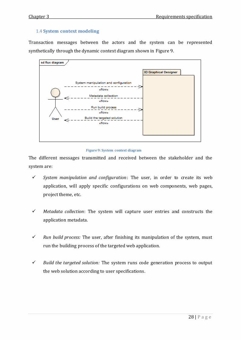
System context modeling 1.4
Transaction messages between the actors and the system can be represented
synthetically through the dynamic context diagram shown in Figure 9.
Figure 9: System context diagram
The different messages transmitted and received between the stakeholder and the
system are:
System manipulation and configuration: The user, in order to create its web
application, will apply specific configurations on web components, web pages,
project theme, etc.
Metadata collection: The system will capture user entries and constructs the
application metadata.
Run build process: The user, after finishing its manipulation of the system, must
run the building process of the targeted web application.
Build the targeted solution: The system runs code generation process to output
the web solution according to user specifications.

Chapter 3 Requirements specification
29 | P a g e
Capture of functional requirements 2.
After presenting main goals of our work and describing preliminary
functionalities, this section is fully dedicated to identify what the project should do and
how it is expected to perform. And thus by specifying functional requirements and
modeling the use case diagram.
2.1 Functional requirements specification
The IO Graphical Designer has to address the following functional requirements:
Graphically create a web application:
The user can visually create a web application with no need of coding. And thus by
creating web pages, adding personal configuration to web elements, and applying
personal customization. The user is provided with some features such as edit code,
preview page, delete included web element or even an entire page.
Generate the skeleton of web solution for .NET platform:
The system must generate a functional web application according the ASP .NET Web
Form specifications and to user manipulations. The code generator engine generates
the full web presentation layer and the skeleton of others application layers.
Manage project:
The user must be able to save the project and obviously load. The graphical designer
management project will also offer the ability to save project versions and to load
project from existing folder or from backups.

Chapter 3 Requirements specification
30 | P a g e
The table below details the list of use cases within a textual description:
Use case Sub use case Description
Create project
Create a virgin project by entering project
path or keeping the default workspace
folder.
Create web page Create a new page by entering the name of
the page and choosing the type.
Build web page
Arrange the entire page layout by setting
elements containers.
Drag and drop web elements into a specific
layout, enter needed configurations and
wanted customization.
Modify web page Modify web element User can modify its manipulation of created
page. He can even delete an included web
element. Modify page layout
Delete web element
Edit code Edit existing page code in the project for
multiple programming languages.
Preview page
Preview a created page in the browser
before building the final solution.
Delete web page Delete an entire web page from the project.
Save project
If the project is first created, the system
save project metadata. Otherwise a choice
between saving a new version of the
project and overriding the existing one is
demanded.
Load project
Load from the workspace folder or from
backups. The system loads the project from
metadata specification.

Chapter 3 Requirements specification
31 | P a g e
Build web
solution
The system extract metadata, run templates
and generate the skeleton of the web
solution.
Style project Change the theme style of the project.
Table III: Preliminary description of functional requirements
2.2 Use case diagram
Having identified the use cases, we can represent the functional requirements
graphically via use case diagram as shown in Figure 10:

Chapter 3 Requirements specification
32 | P a g e
Figure 10: Use case diagram

Chapter 3 Requirements specification
33 | P a g e
2.3 Use case organization
The organization of our use cases is done through package diagram
decomposition. Each use case belongs to one specific package having a higher level of
abstraction.
Table IV shows the decomposition of use case by package:
Use case Package
Create project
Module of graphical web application
creation
“Graphical Designer”
Create web page
Modify web page
Build web page
Modify web page
Edit code
Preview page
Delete web page
Style project
Load project Module of project management
“Project Management” Save project
Build web solution Module of building web application
“Web app builder”
Table IV: List of use cases organized by package

Chapter 3 Requirements specification
34 | P a g e
We illustrate below (Figure 11) the use case package diagram:
Figure 11: Use case package diagram
Capture of non-functional requirements 3.
This section is dedicated to identify the required specific improvements to be
delivered within the system.
3.1 Responsive web design
What is responsive design?
Responsive design is an approach that suggests that design and development
should respond to the user’s behavior and environment taking into consideration
screen-size, platform and orientation. The practice consists of common approaches and
techniques to apply a single design that has the same look and feel across all devices and
platforms. As the user switches between their desktop, laptop, tablet and even mobile
phone, the web application will automatically switch to accommodate for resolution,
image size and scripting abilities [12] [13].
The particularity of responsive design as opposed to the old and tedious method
(develop a different design, layout and styling for each device size on the market) is that
will allow the web application to actually respond to the environment of the user and
server the most appropriately designed option.

Chapter 3 Requirements specification
35 | P a g e
“You put water into a cup it becomes the cup. You put water into a bottle it becomes the
bottle. You put it in a teapot, it becomes the teapot” A quote by Josh Clark from his book
Seven deadly mobile myths [14].
The key point is to generate a fluid, flexible and adaptive web solution that
responds to the ever-changing landscape of devices, browsers, screen sizes and
orientations
The challenge is about offering the user a graphical tool to create web pages with
no need for programming knowledge and generating a responsive web design. This
compromise between totally configured and customized web page and conformity to
nowadays web demands such as design responsiveness is one of the primary goals of
our work.
3.2 Lightweight web elements
To keep the application up-to-date within modern technologies, the generated
web controls must feature HTML5 and CSS3-based render mode. The modern,
lightweight rendering mode saves a big portion of the HTML, CSS and resources used by
the controls, thus improving their performance.
3.3 Interactivity
IO development team is working on dashboards enterprise web applications
which require high interactivity and responsiveness. It is all about user experience. Real
time data visualization, asynchronous server call and client side techniques are essential
to improve user interactivity.
Conclusion
Throughout this chapter, we have specified the functional and non-functional
requirements of our project. This specification allows us to take the next phase in RUP
process namely the phase of analysis and design.

Chapter 4: Analysis & Design

Chapter 4 Analysis & Design
37 | P a g e
Introduction
he goal of the Analysis & Design phase is to show how the system will be
realized in the implementation phase. We want to build a solution that
performs the functions specified in the latter chapter, and fulfills all its requirements.
We start by describing the behavior of the graphical designer using the analysis model.
Then, we expose the target web application design, global and detailed system
architecture.
1 Analysis
The goal of this section is to analysis the system functionalities. We will analyze
the most important use case “Build web page”.
“Build web page” use case
The graphical designer provides features to visually build a web page and customize it.
Indeed, the user benefits from the following functionalities:
Add new page.
Set page layout.
Add web elements and configure them.
Modify configuration
Etc.
T

Chapter 4 Analysis & Design
38 | P a g e
Table V presents a textual description of the “Build web page” use case:
Main Actor: User
Goal: Build web page
Summary: The user can graphically build a web page by setting its layout and adding
web elements. He can configure and customize each web element. He can also apply
modifications by deleting existing web elements, changing layout or modifying
configurations.
Preconditions:
Create a project. A web page is associated to a specific project.
Main Scenario:
Add web page. 1
Set page layout. 2
Add web element. 3
Configure web element. 4
Validate configuration. 5
Close page designer. 6
Alternative scenario: None
Post conditions:
The web page is added to the current project.
The web page metadata is extracted from user configurations and inputs.
Table V: Textual description of the "Build web page" use case
Title: Build web page

Chapter 4 Analysis & Design
39 | P a g e
In order to illustrate the use case diagram defined above, we choose to model it within
the system sequence diagram as following:
Table VI: System sequence diagram "Build web page"

Chapter 4 Analysis & Design
40 | P a g e
Once the user creates a new web page, the system displays the page designer with
default layout: four rows, header, footer, left banner and a right banner. The user starts
by setting columns for each row. He can add rows to the layout or delete a predefined
container.
For each layout, the user adds web elements and applies custom configurations.
Meanwhile, the graphical designer data binds user inputs to the page elements in order
to extract metadata.
2 Design
After analyzing the most important use case of our project which results in
sequence diagram model, we aim to display in this section the global and detailed design
of our proposed solution.
We proceed first by identifying the generated web application architecture. Then we
expose the solution design.
2.1 Generated web application design
Respecting the code generation process detailed in the state of the art section (cf.
chapter 2, p.17), we need to define the design architecture of the targeted web
application.
And referring to the specification requirements, the generated web solution has to
follow these criteria:
ASP .NET Web Forms application.
N-layer architecture design (cf. see chapter 3, p.25).
Interactivity (cf. see chapter 3, p.35).
To respond to the latter requirements, we need to add some improvements on the ASP
.NET Web Forms model. We detail in the next paragraph the limits of Web Forms
technology comparing to nowadays web demands.

Chapter 4 Analysis & Design
41 | P a g e
2.1.1 Limits of ASP .NET web forms solutions
The ASP .NET Web Forms is based on the concept of post backs and view state.
The current page contains just one HTML form and one or more submit buttons. When
the user clicks, the content is uploaded and the new page is downloaded. The new page
is created based on the content that page controls have stored in the view state and
based on the outcomes of the post back event. The Web Forms model was created to
make Windows and Web development nearly the same in the .NET platform.
Nowadays, web development acquires a radically different set of features and
skills (HTML, JavaScript, DOM and CSS). The Web Forms model sacrificed, almost
entirely, JavaScript and client side interaction and is less adequate every day for the
following limits:
No client side interaction; based on post back mechanism which require server
invocation for every user event.
Server side logic: every request triggers a call to the server which responses back
the entire web page.
No partial update; no asynchronous server call.
Take no advantage of web new features (offers heavyweight web controls).
In order to design an interactive application, we need to add new few features to the old
Web Forms model.
Adding AJAX capabilities to ASP .NET Web Forms architecture, we can move back to
original web characteristics and demands.
2.1.2 What is AJAX?
AJAX, Asynchronous JavaScript and XML, refers to using a set of specific browser
technologies to build pages [15]. And these browser technologies have been around for
ten years now- XMLHttpRequest, DOM, and JavaScript. With AJAX, web applications can
send data to, and retrieve data from, a server asynchronously without interfering with
the display and behavior of the existing page.

Chapter 4 Analysis & Design
42 | P a g e
2.1.3 AJAX architecture
The AJAX architecture is not too complicated. It’s based on two layers: C lient layer and
Service Layer as demonstrated above:
Figure 12: AJAX architecture
The client layer contains JavaScript code and makes intensive use of the browser’s
native XMLHttpRequest object. The service layer presents a collection of public HTTP
endpoints enabled to receive calls from the client browser.
XMLHttpRequest Object:
The AJAX development model revolves around one common software element –the
XMLHttpRequest object. The availability of this object in most browsers’ object model is
the key to the current ubiquity and success of AJAX applications.
“Originally introduced with Internet Explorer 5.0, the XMLHttpRequest object is an
internal object that the browser publishes to its scripting engine. In this way, the script
code found in any client page—typically, JavaScript code—can invoke the object and
take advantage of its functionality [15].”
JSON (JavaScript Object Notation):
JSON presents a more lightweight and efficient alternative to XML for exchanging data
over the web. Just like XML, JSON is text based, but is simpler and more human readable
than full XML.
To add AJAX capabilities, we only need to add AJAX service layer and some enrichment
on the web layer
AJAX
Client
Layer
(JavaScript)
AJAX
Service
Layer
XMLHttpRequest
JSON

Chapter 4 Analysis & Design
43 | P a g e
2.1.4 Generated web application design
Figure 13: Generated web application design
As illustrated in the Figure 13, the targeted solution design is ASP .NET AJAX enabled
Web Forms application. We add Ajax capabilities in order to respond to interactivity
requirement (cf. see chapter 3, p.35).
Web layer: runs in the browser and contains client side web technologies (HTML5,
CSS3, JavaScript, etc.) which are handled by almost browsers. The web layer contains
also some embedded code (JavaScript code) to make asynchronous calls to the service
layer: AJAX client layer.
Service layer: is the middleware between the front-end (web layer) and back-ends
(business and data layers). The service layer responds to the client requests.
Business layer: contains business entities which represent model representations of
the application real world.
Data layer: presents the data access logic of the web application. It provides techniques
to retrieve and store data into data sources (XML files, databases, etc.)
Web Layer Services Layer
Business Layer
Business Entities
Data Layer
Data Access Compo-
nents
Data
Sources
AJAX
Service
Layer
AJAX
Client
Layer
XMLHttpRequest
JSON

Chapter 4 Analysis & Design
44 | P a g e
2.2 System global design
Our solution is composed of 2 main modules which are described below:
Figure 14: Global design
Graphical Designer:
The graphical designer presents the center of gravity of our work. It allows users to
create, configure, customize and build the web applications by offering a set of features
(drag & drop, preview mode, cote edition, etc.).
The graphical designer extracts the metadata for the code generator module.
Code generator module:
The code generation engine implemented according a template based approach. It
provides code templates for different application layers: Web layer (web page
templates, web elements templates), Service Layer (services templates). The code
generator uses these templates to generate code from the extracted metadata, outputs
application layers and builds the final web solution.
Next, we will display the architecture of our proposed solution, as well as its detailed
design. We will begin by giving a global view of the entire system and its packages. Then,
we will detail the design of each one.
Code
Generator
Module
Graphical
Designer
Module

Chapter 4 Analysis & Design
45 | P a g e
2.3 Graphical designer module
The graphical designer module is a rich client application for the following
considerations:
The application will be deployed on client PCs.
It must provide high user interactivity and responsiveness.
And does not require advanced graphics or media capabilities of web
applications.
Rich client applications can offer rich UI4 functionality, improved user experience and
high performance for applications that operate in standalone environment [16].
.NET platform provides development technologies and tools, such as Windows Forms,
Windows Presentation Foundation (WPF), and Microsoft Office Business Application
(OBA), which allow developers to quickly and easily build rich client applications. We
opt for Windows Forms technology for the following reasons:
The graphical designer does not require rich data visualization or media support
offered by WPF5.
The application should execute with minimal hardware requirements.
User interactivity and responsiveness.
2.3.1 Graphical designer global architecture
A typical rich client application will be structured as a multilayered design
consisting of user experience (presentation layer), business, and data layer.
The presentation layer is the topmost level of the application. As it name
suggests, the presentation layer is exclusively responsible for the data presentation and
contains the components needed to interact with the user (forms, controls, etc.).
As for the business layer, it encapsulates the core business functionality of the
application and contains the business objects. A business object is a component that
encapsulates the data and business processing logic for a real world element. For our
case, real world elements present web pages and web controls that construct the
presentation layer to be generated.
4 User Interface 5 Windows Presentation Foundation : .NET technology for developing rich client application

Chapter 4 Analysis & Design
46 | P a g e
And the data layer contains components to store data in prepared sources. They
also have the responsibility to retrieve persistent data from data sources and place it
into business objects. This is called data access logic.
Figure 15 further explains the global architecture of the project:
Figure 15: Graphical designer global architecture
Pre
sen
tatio
n
La
ye
r
Bu
sine
ss
La
ye
r
Da
ta
La
ye
r
UI Components
Presentation Logic Components
Business Entities
Data Access Components
Data
Source

Chapter 4 Analysis & Design
47 | P a g e
2.3.2 Graphical designer package diagram
The following figure illustrates the package diagram of the graphical designer
application. Respecting the chosen architecture, we dispose of three packages: the UI
package (for the presentation layer), business (for the business layer) and DAL6 package
(for the data layer):
Figure 16: Graphical designer package diagram
This is a brief description of each package:
GraphicalDesigner.UI package:
The user interface package is considered as the presentation layer of the
graphical designer application. It contains forms, user controls and custom controls used
to handle user interactions, configurations and inputs.
The UI package invokes the business package in order to construct business objects,
display data and handle data binding7.
GraphicalDesigner.Business package:
The business package models the application business objects. Business objects
present the real world of the application.
6 Data Access Layer 7 Data binding is a concept used by Windows Forms technology to bind a data structure to a UI component.

Chapter 4 Analysis & Design
48 | P a g e
Indeed, it models a project graphically created by a simple user: site project, web pages,
web elements, etc.
The Business package is invoked by the presentation package in order to edit and bind
data for business entities. And it invokes the DAL package to store or retrieve data.
GraphicalDesigner.DAL package:
The Data Access Layer package contains access components to store/retrieve
data into/from data source. For our project, the data source present XML files. Actually,
it is the metadata used by the code generator module.
2.3.3 Graphical designer business package
This package is considered as the business layer for the GD application. It
contains business entities that model the web application to be generated as shown in
the figure below:
Figure 17: Graphical designer business layer

Chapter 4 Analysis & Design
49 | P a g e
Indeed, this package (Figure 17) illustrates the business model of a project to be built
graphically by the user. As we can notice, the Project is composed of WebPage(s) and
each web page is composed of WebElement(s).
The WebElement is an abstract class that aggregates the global attributes for every
HTML tag8. It presents the business entities façade.
Business entities are grouped into Web Elements package which is composed of two
packages: HtmlElement (models entities for simple Html web elements) and
ChartElements package (models entities for chart web elements).
We detail below the class diagram for each sub package. We start by the HtmlElements
package as demonstrated in Figure 18.
8 In the HTML syntax, elements are written with a start tag and an end tag, with the content in between.

Chapter 4 Analysis & Design
50 | P a g e
Figure 18: htmlElements' package class diagram

Chapter 4 Analysis & Design
51 | P a g e
In order to understand this package, the class diagram below is simplified.
Therefore, it contains only some html elements’ classes since the same logic is repeated.
Actually, we can distinguish two main categories of html web elements: simple and
composed. The latter are composed of other html elements (such as div element, table,
panel, etc.).
And from the class diagram, we can also notice that every html element (simple or
composed) inherits from WebElement class and implements the interface
IHTMLElement.
The ChartElements package has nearly the same logic which is illustrated in the Figure
19.
The main class of this diagram is ChartElement which is an abstract class inherited from
the WebElement class since every ChartElement has an html tag. The ChartElement
abstracts common chart options (title, subtitle, axis, series, etc.). The different chart
classes which represent different chart types (bar, gauge, line, etc.) inherit from
ChartElement class and implement the IHTMLElement and the IJQueryElement interfaces.

Chapter 4 Analysis & Design
52 | P a g e
Then, we expose the class diagram for the ChartElements package.
Figure 19: chart elements' package class diagram

Chapter 4 Analysis & Design
53 | P a g e
Once we have detailed the model of web elements to be included into web pages,
we can move to detail the WebPages package.
This package has a main class WebPage which models the web page layout. Page
layouts are templates that define how a page should look, what page fields and content
fields are available and exactly which web elements should be present on the page.
As illustrated in Figure 20, a web page is composed of different containers: header,
footer, side bars and rows. The latter is composed of columns which contain web
elements. Every container inherits from the WebElement abstract class since they
dispose of an html tag.

Chapter 4: Analysis & Design
54 | P a g e
Figure 20: WebPages' package class diagram

Chapter 4 Analysis & Design
55 | P a g e
2.3.4 The Graphical Designer UI package
The UI package is considered as the presentation layer of the graphical designer
module. It is composed of a main windows form which uses a set of user controls to
perform different tasks (such as CodeEditor user control, toolbox user control, etc .) and
a collection of editors. Editors are forms that encapsulate business entities and have the
responsibility for displaying and binding data.
Figure 21 illustrates an overview of the UI layer. In fact, it contains a MainForm
class which presents the main user windows. The latter invokes the UserControls
package and the Editors package to perform user interactions.
Figure 21: Graphical Designer.UI package
The UserControls package is a collection of custom Winforms9 controls responsible for
specific tasks. This best practice allows reusability of these features along the user
manipulation. For example, the CodeEditor control is used as many times as the user edit
a page code.
The Editors package is the bridge between user inputs for and web elements entities. For
each web element, we dispose of an editor which takes the task of handling bidirectional
data binding.
9 Windows Forms

Chapter 4 Analysis & Design
56 | P a g e
We detail below each package class diagram. We begin with the Editors package as
shown in Figure 22.
Figure 22: Editors class diagram

Chapter 4 Analysis & Design
57 | P a g e
The UserControls class diagram is illustrated below:
Figure 23: UserControls class diagram

Chapter 4 Analysis & Design
58 | P a g e
2.3.5 Graphical designer DAL package
The Data Access Layer package contains access components to store/retrieve data
into/from XML data source. Actually, we have two data access object: webPageDAO and
projectDAO.
Figure 24 illustrates the class diagram of the DAL package.
Figure 24: DAL class diagram
Conclusion
Throughout this chapter, we gave an overview of the proposed solution’s design .
In fact, we opted for a layered architecture that permits to increase application
performance, scalability and flexibility.
Once the system’s architecture and the project’s packages are defined, we can
move to the next chapter and present the achieved work.

Chapter 5: Implementation & Test

Chapter 5 Implementation & Test
60 | P a g e
Introduction
n this chapter, we provide an overview of the achieved work during the
internship. At first, we start by presenting our development environment.
After that, we present the project planning and display the achieved work. Finally we
explain different tests performed during the project lifecycle.
1 Development environment
In this section, we present the development environment by giving an overview
of the used software and tools, used technologies and used programming languages.
Used software and tools 1.1
Internet Information Services 7 (IIS 7): It is a component of the Microsoft
Windows operating system. It permits to turn a computer into a web server that
can provide HTTP and FTP publishing services. IIS also permits to host and
manage Web sites and other internet content [17].
Visual Studio 2012: It is an integrated development environment (IDE) that
provides a set of tools and services to develop web, desktop, or mobile
applications. The power of Visual Studio is that it permits develop an entire
application with a single tool without leaving the development environment. In
our project, we used Visual Studio in implementing the graphical designer
module, the project management module, and the install shield.
Sparx Systems Enterprise Architect 7.5: Enterprise Architect is a visual modeling
and design tool based on UML and which supports the design and construction of
software systems, modeling business processes, and modeling industry based
domains. Enterprise architect helped us throughout the RUP phases in delivering
the required artifacts.
I

Chapter 5 Implementation & Test
61 | P a g e
Microsoft office project 2010: Microsoft Project is a project management
software program, which is designed to assist a project manager in developing a
plan, assigning resources to tasks, tracking progress. Microsoft project helped us
during the entire project life-cycle by organizing and scheduling our iterations
and releases.
Used technologies 1.2
Windows Forms: Windows Forms is a technology provided by Microsoft .NET for
developing smart clients. Smart clients are graphically rich applications that are
easy to deploy and update, can work when they are connected to or disconnected
from the Internet, and can access resources on the local computer. In Windows
Forms, a form is a visual surface on which we display information to the user. We
ordinarily build Windows Forms applications by adding controls to forms and
developing responses to user actions, such as mouse clicks or key presses. A
control is a discrete user interface (UI) element that displays data or accepts data
input [18].
ASP .NET: ASP .NET is a server-side Web application framework designed for
Web development to produce dynamic Web pages. It is offered by Microsoft that
allows programmers to build dynamic web sites, web applications and web
services [19] .
ASP .NET Web Forms: ASP .NET Web Forms is a part of the ASP.NET web
application framework and is included in Visual Studio IDE. Web Forms are pages
that users request using the browser. These pages can be written using a
combination of HTML, client-script, server controls, and server code. When users
request a page, it is compiled and executed on the server by the framework, and
then the framework generates the HTML markup that the browser can render. An
ASP.NET Web Forms page presents information to the user in any browser or
client device [20].

Chapter 5 Implementation & Test
62 | P a g e
LINQ to XML: LINQ refers to .NET Language-Integrated Query which simplifies
data access by offering a familiar programming language. LINQ to XML is a built-
in LINQ data provider that allows creating, reading, and writing XML-based data.
The XML data source may be a file, in-memory XML, or a remote resource [21].
AJAX (Asynchronous JavaScript and XML): It is a group of interrelated web
development techniques used on the client-side to create asynchronous web
applications. With AJAX, web applications can send data to, and retrieve data from, a
server asynchronously without interfering with the display and behavior of the
existing page.
JQuery: “The Write Less, Do More, JavaScript Library” [22]. JQuery is a cross-
platform JavaScript library designed to simplify the client-side scripting of HTML.
It is free, open source software, licensed under the MIT License. JQuery’s syntax is
designed to make it easier to navigate a document, select DOM elements, create
animations and develop Ajax applications.
Used programming languages 1.3
ASP .NET (ASP DotNet): Active Server Pages (ASP) is Microsoft’s server side
script engine for dynamically generated web pages.
C# (C-sharp): C# is an object oriented and type-safe programming language. C#
combines the height productivity of Rapid Application Development (RAD)
languages like Java and the raw power of C++.
JavaScript: JavaScript is a scripting language commonly implemented as part of
web browser in order to create enhanced user interfaces and dynamic websites.
HTML5: HTML5 is a markup language used for structuring and presenting
content for the World Wide Web and a core technology of the internet. It is the
fifth revision of the html standard and a candidate recommendation of the World
Wide Web Consortium. Its core aims to improve the language with support for
the latest multimedia while keeping it easily readable by humans and
consistently understood by computers and devices [17].

Chapter 5 Implementation & Test
63 | P a g e
CSS3 (Cascading Style Sheets): CSS3 it is a language used for describing the
presentation semantics of a document written in a markup language and
commonly applied to style web pages.
XML (eXtensible Markup Language): XML is a markup language that defines a set
of rules for encoding documents in a format that is both human and machine
readable. The design goals of XML emphasize simplicity, generality, and usability
over the Internet. We used Xml language to represent the application metadata.
XSLT (eXtensible Stylesheet Language Transformation): XSLT is a language that
converts XML documents into other XML documents, or HTML documents, or
into any type of text output.
JSON (JavaScript Object Notation): JSON presents a more lightweight and efficient
alternative to XML for exchanging data over the web. Just like XML, JSON is text
based, but is simpler and more human readable than full XML.

Chapter 5 Implementation & Test
64 | P a g e
2 Realization
This section presents the achieved work during the internship. At first, we start
by giving an overview of the code generator engine. Then we present the graphical
designer module. And finally we describe a practical case study to demonstrate the
process of creating a web application using our graphical designer solution.
2.1 Code generator module
The realization of the code generator engine (Figure 25) consists basically on the
implementation of code templates: templates for generated web elements, page layout,
web pages, Ajax service classes, etc.
Figure 25: Code generator engine

Chapter 5 Implementation & Test
65 | P a g e
The table below describes specific templates and its purposes (Appendix A contains an
exhaustive list of templates with detailed description).
Template Description
Areachart.xslt Template to generate code related to area chart web
element.
Linechart.xslt Template to generate code related to line chart web
element.
Column.xslt Template to generate a page’s column container. The
template includes all the web elements templates and
calls needed ones according to metadata specification.
Row.xslt Template to generate row’s page layout. The template
will simply run a loop and run template for each
column.
Page.ajax.xslt Template to generate the skeleton of a page service
layer. It generates skeleton of Ajax methods to be called
by the web page.
div.xslt Template to generate code for a div html element. The
template includes every web element template and calls
needed ones according to the metadata.
webpage.xslt Template to generate a web page code in order to
generate the web layer. The template simply runs
template for every container constructing the page
layout: header, footer, row, etc.
Table VII: Code generator templates
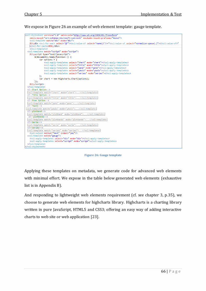
Chapter 5 Implementation & Test
66 | P a g e
We expose in Figure 26 an example of web element template: gauge template.
Figure 26: Gauge template
Applying these templates on metadata, we generate code for advanced web elements
with minimal effort. We expose in the table below generated web elements (exhaustive
list is in Appendix B).
And responding to lightweight web elements requirement (cf. see chapter 3, p.35), we
choose to generate web elements for highcharts library. Highcharts is a charting library
written in pure JavaScript, HTML5 and CSS3; offering an easy way of adding interactive
charts to web site or web application [23].

Chapter 5 Implementation & Test
67 | P a g e
Line chart :
The line chart is
represented by a
series of
datapoints
connected with
a straight line.
Line charts are
most often used
to visualize data
that changes
over time.
Bar chart :
A bar chart
displays data in
horizontal bars.
Table VIII: Generated web elements

Chapter 5 Implementation & Test
68 | P a g e
2.2 Graphical designer module
Once detailing the code generator engine and used templates to generate code,
missing artifacts are required which present the application metadata. Metadata is
actually collected from the user inputs and thus through the graphical designer module.
Therefore, we expose in this section an overview of “IO graphical designer” by exposing
main interfaces used to visually build a web application.
Figure 27 presents the application main user interface:
Figure 27: Graphical designer overview
As we notice, we have 4 main blocks in our interface:
Site toolbar which exposes different functionalities for constructing a web
application.
Project explorer that displays project folders and files.
Toolbox that provides web elements to be included into pages.
Property grid to customize web element’s attributes.

Chapter 5 Implementation & Test
69 | P a g e
We can also notice a blank block in the center. This one is responsible for displaying
page designers, code editors, columns designers, etc. It represents the user workspace.
Figure 28 illustrates the default page designer displayed once the user adds a new web
page to the current project:
Figure 28: Web page designer
The user begins by setting the page layout and then dragging & dropping web elements
into specific column’s container. Figure 29 illustrates a column designer within a label
and a line chart element included in.

Chapter 5 Implementation & Test
70 | P a g e
Figure 29: Page's column designer
And finally, for each web element, the user has the ability to add configurations and
personal customizations and thus through web element’s editors. Figure 30 shows the
line chart editor as an example.

Chapter 5 Implementation & Test
71 | P a g e
Figure 30: Line chart editor
The editor below offers customizations for different chart options: general options
(chart tab), legend options (legend tab), X and Y Axis options (Axis tab), etc.
2.3 Scenario for creating a web application
In this section, we describe a scenario for generating a web application using our
graphical designer. The web application is inspired from a developed one by Integration
Objects technical team. Actually, it represents web dashboard for displaying KPI10
indicators.
The web application is composed of three web pages: Overview, KPI and Cost. The
scenario of constructing the web solution graphically is detailed in next paragraphs.
Indeed, we begin first by setting the page layout for each web page. Then, we drag and
drop web elements in each page container and customize its configurations. Finally, one
button click and the complete solution is generated.
10 Key Performance Indicator

Chapter 5 Implementation & Test
72 | P a g e
3.3.1 Setting page layouts
As mentioned previously, we dispose of three pages:
Overview web page: contains two rows. First row has one column and the
second has two columns with the same span11 (see Figure 31).
Figure 31: Overview page layout
KPI web page: contains two rows. First row has two columns: span 8 and span 4.
Second row has one column as show in Figure 32.
11 Unit for column width, vary from 1 to 12

Chapter 5 Implementation & Test
73 | P a g e
Figure 32: KPI page layout
Cost: is composed of two rows (see Figure 33). First row contains two columns
(span 8 and span 4). Second contains also two columns (span 6 and span 6).

Chapter 5 Implementation & Test
74 | P a g e
Figure 33: Cost page layout
3.3.2 Adding web elements
Using the page navigator, we move to each column, drag web element from the
toolbox and drop it into the specific container.
We detail only the construction of the first web page (Overview) since the same logic is
repeated.
The first column contains a line chart web element (see Figure 34). Second contains a
bar chart web element (Figure 35). And the third column has an area spline web element
(Figure 36).
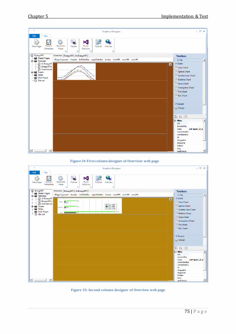
Chapter 5 Implementation & Test
75 | P a g e
Figure 34 First column designer of Overview web page
Figure 35: Second column designer of Overview web page

Chapter 5 Implementation & Test
76 | P a g e
Figure 36: Third column designer of Overview web page
3.3.3 Configuring web elements
Once we have included web elements into columns, we need to add some
customizations. For that, a simple double click on a web element and the related editor
is displayed with default configurations.
We expose below the configuration of the line chart element. The editor offers
customization for different JQuery options. We only illustrate the Chart options (Figure
37) and the Axis options (Figure 38).

Chapter 5 Implementation & Test
77 | P a g e
Figure 37: Line chart editor, chart option tab
Figure 38: Line chart editor, Axis option tab

Chapter 5 Implementation & Test
78 | P a g e
3.3.4 Build web solution
Finally, after completing the configuration for each web element, we only need to
click the “Build solution” button and the complete web application is generated within a
Visual Studio solution as shown below:
Figure 39: KPI solution
Then, we expose the web pages’ screenshots:

Chapter 5 Implementation & Test
79 | P a g e
Figure 40: Overview web page
This web page contains three chart types: line, bar and spline chart.

Chapter 5 Implementation & Test
80 | P a g e
Figure 41: KPI web page
The KPI web page contains a pie, gauge and scatter chart.

Chapter 5 Implementation & Test
81 | P a g e
Figure 42: Cost web page
Cost web page contains area, gauge, spline and pie chart.
3 Test & Validation
In order to test our work, we perform some corrections’ tests as detailed in next
paragraphs.
4.1 Generated code
One of the primordial objectives of our solution is to maximize the amount of
generated code. We test the generated code comparing to the handwritten one of the
KPI application. Since we have focused on the web layer, we expose below a comparison
between the number of code lines for each web page and we compare also the size of
each application.

Chapter 5 Implementation & Test
82 | P a g e
Number of code line Size (octet)
Generated
application
Overview KPI Cost
2 082 739 245 235 284
Final application 294 381 334 2 086 999
Percentage 83 % 62 % 85% 99%
Table IX: Amount of generated code
As illustrated in Table IX, we can notice that almost 80% of code is generated by our
solution.
4.2 Responsive design validation
In order to test the responsive design feature, we run the application in different
screen sizes and observe the adaption of the design. We test on three types of screen:
large (Figure 43), medium (Figure 44) and small (Figure 45)
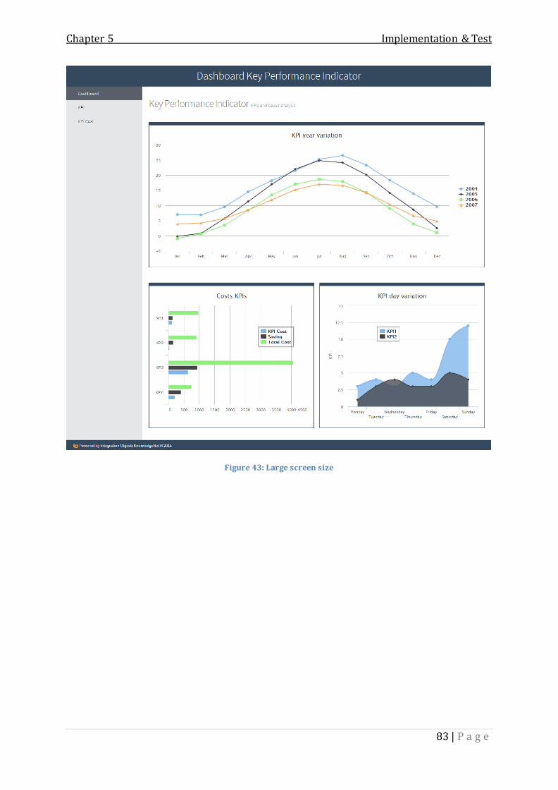
Chapter 5 Implementation & Test
83 | P a g e
Figure 43: Large screen size

Chapter 5 Implementation & Test
84 | P a g e
Figure 44: Medium screen size

Chapter 5 Implementation & Test
85 | P a g e
Figure 45: Small screen size

Chapter 5 Implementation & Test
86 | P a g e
We can clearly notice the responsiveness to the screen-size variations. In the medium
size, page layouts are minimized and the banner disappears. The same as the small size ,
columns are vertically aligned to fit the page width.
Conclusion
Throughout this chapter, we tried to present the implementation phase of the
solution. We have started be describing the development environment. Then, we have
presented a global overview of our solution and a practical scenario. Finally, we have
finished by performing tests to validate our application.

General Conclusion
87 | P a g e
Our final of study project, developed within Integration Objects, consisted in
designing and implementing a graphical environment allowing users to visually create
web applications without the need of programming skills. This graphical designer,
provided with a code generator engine, allows end users to efficiently and easily build
enterprise web application dashboards. Therefore, this project allows Integration
Objects’ technical team to considerably minimize the development time when building
customer’s web solutions and allows end users to easily customize their web
applications.
The code generator engine developed during our internship can be used as a
daily utility by Integration Objects’ developers to automate repetitive tasks and it can be
considered as an entirely independent product.
In this report, we first focused on the understanding of the discipline by studying
the concept of code generation and reviewing the existing techniques. The next step was
to study and analyze the features to design and implement in our solution and bring out
the functional and non-functional requirement of our project. We then proceeded to the
design phase, by detailing the architecture of our application as well as static and
dynamic design through the development of package and class diagrams.
Finally, we concluded the report by presenting the implementation and test phase of our
project. This chapter describes the development environment, and exposes the work
done through screenshots which cover the most important features of the solution.
This project allowed me to discover new concept such as code generation, as well
as to increase my technical knowledge in web and .NET development.
The most challenging part was the validation of the code generation as a solution for our
problematic. Selecting the template based approach as the right approach to follow was
also important to the solution design and implementation.
General Conclusion

General Conclusion
88 | P a g e
In terms of perspectives, we expect to improve our product by generating
additional web elements and adding more customization features within the generated
web application.
We also can consider generating back-ends layers from the data sources in addition to
the adopted user interface driven approach in generating the web solution.
Another possible improvement is to provide various targeted architecture to be applied
on the web solution, not only Ajax web based application. We can provide MVC pattern,
cloud applications and even SharePoint web parts.

Bibliography
89 | P a g e
[1] D. Savic, S. Vlajic and S. Lazarevic, "A Generator of MVC-based Web Applications,"
World of Computer Science and Information Technology Journal, pp. 147-156.
[2] Integration Objects, 2014. [Online]. Available: http://www.integrationobjects.com/.
[3] Rational Software Development Company, "Rational Unified Process, Best Practices
for Software Development Teams," Rational Software White Paper, 2011.
[4] K. Dollard, Code Generation in Microsoft .NET, Apress, 2004.
[5] Arnoldus, M. v. d. Brand and A. Serebrenik, Code Generation with Templates,
Atlantis Press, 2012.
[6] J. Herrington, Code generation in action, Manning Publications Co., 2003.
[7] Krzysztof Czarnecki and Simon Helsen, "Classification of Model Transformation
Approaches," Workshop on Generative Techniques in the Context of Model-Driven
Architecture, 2003.
[8] A. Bajovs, Oksana Nikiforova and Janis Sejans, "Code Generation from UML Model:
State of the Art," Applied Computer Systems, 2013.
[9] J. Conallen, "Modeling Web Application Architectures with UML," Rational Software,
1999.
[10] T. Parr, "Enforcing Strict Model-View Separation in Template Engines," WWW'04:
International Conference on World Wide Web, pp. 224-233, 2004.
[11] CodeOnTime, 2014. [Online]. Available: https://codeontime.com/.
[12] R. Williams, "responsive-design-asp-net," 2013. [Online]. Available:
https://rionscode.wordpress.com/tag/responsive-design-asp-net/.
[13] E. Marcotte, "responsive-web-design," 2010. [Online]. Available:
Bibliography

Bibliography
90 | P a g e
http://alistapart.com/article/responsive-web-design.
[14] C. Josh, Seven Deadly Mobile Myths, 2012.
[15] D. Esposito, Microsoft ASP.NET and AJAX: Architecting Web Applications, Microsoft
Press, 2009.
[16] Microsoft Press book, Microsoft Application Architecture Guide, 2009.
[17] "wikipedia," [Online]. Available: http://en.wikipedia.org/.
[18] MSDN Magazine, "Windows Forms Overview," 2014. [Online]. Available:
http://msdn.microsoft.com.
[19] MacDonald, Matthew, Szpuszta and Mario, Pro ASP.NET 2.0 in C#, Apress, 2005.
[20] "what-is-web-forms," Microsoft, 2014. [Online]. Available: http://www.asp.net/.
[21] T. Patton, TechRepublic, 2008. [Online]. Available: http://www.techrepublic.com/.
[22] JQuery, 2014. [Online]. Available: http://www.jquery.com.
[23] HIGHCHARTs, 2014. [Online]. Available: http://www.highcharts.com/.

Appendix A Templates’ description
91 | P a g e
This appendix is a complement for Table VIII which describes the developed templates:
Template Description
Areachart.xslt Template to generate code related to area chart web
element.
Areasplinechart.xslt Template to generate code for area spline chart type.
Barchart.xslt Template to generate code for bar chart web element.
Bubblechart.xslt Template to generate code for bubble chart web element.
Linechart.xslt Template to generate code related to line chart web
element.
gauge.xslt Template to generate gauge web element code.
Piechart.xslt Template to generate pie chart web element code.
Scatterchart.xslt Template to generate scatter chart web element code.
Splinechart.xslt Template to generate spline web element code.
Column.xslt Template to generate a page’s column container. The
template includes all the web elements templates and
calls needed ones according to metadata specification.
Row.xslt Template to generate row’s page layout. The template
will simply apply a loop and run its columns’ templates.
header.xslt
footer.xslt
Template to generate page’s header and footer. The
templates include specific web elements’ templates, such
as label, headings, image, etc.
Sidebar.xslt Template to generate right or left banner container. It
calls templates for specific web elements (menu, list
items, etc.)
Appendix A: Templates’ description

Appendix A Templates’ description
92 | P a g e
div.xslt Template to generate code for a div html element. The
template includes every web element template and calls
needed ones according to the metadata.
PageLayout.xslt Template to generate the page layout code. It will be used
by the webPage template to construct fields and
containers.
Page.ajax.xslt Template to generate pages’ service layer. It generates
the skeleton of Ajax methods to be called by the web
page.
webpage.xslt Template to generate a web page code in order to
generate the web layer. The template simply runs
template for every container constructing the page
layout: header, footer, row, etc.
Page.code_behind.xslt Template to generate the skeleton of a web page code
behind.
Table X: Templates' description

Appendix B Generated web elements
93 | P a g e
This is a complete table exposing the advanced web elements provided and generated
by our graphical designer.
Areaspline
chart:
The areaspline
chart is an area
chart, only the
line is a spline
instead of
straight lines.
Pie chart:
The pie chart is
a circular chart
divided into
sectors which is
proportional to
the quality it
represents.
Appendix B: Generated web elements

Appendix B Generated web elements
94 | P a g e
Scatter chart:
The scatter
chart draws a
single point for
each point of
data in a series
without
connecting
them.
Bubble chart:
The bubble
chart draws a
bubble for each
point of data in
a series.

Appendix B Generated web elements
95 | P a g e
Area chart:
The area chart
functions the
same as a line
chart only it
fills the area
between the
line and the
threshold.
Gauge chart:
The gauge chart
is a
speedometer-
like widget.
Spline chart:
The spline chart
draws a curved
line between the
points in a data
series.
Table XI: Generated web elements (complete list)