gps flight data recorder zander gp 940 - … · gp940e 01/97 27.02.97 1 version 01/97 gps flight...
TRANSCRIPT

GP940E 01/97 27.02.97 1
Version 01/97
GPS FLIGHT DATA RECORDER
ZANDER GP 940
MANUAL
content:
1. Introduction 2
2. Installation into glider 3
3. Turning on the GP940 4
4. Connecting GP940 to PC 5
5. Charging internal battery of GP940 6
6. Entering data from glider computer SR940 7
7. Preparing waypoints and routes for SR940 / GP940 8
8. How to use GP940 10
9. Technical data 13
10. Wiring diagrams 14
11. Pin assignments of connectors 16
12. Calibration chart for altimeter of GP940 17
Annex: IGC approval of GNSS Flight Data Recorder ZANDER GP940 18
Warning:The recorder box must not be opened! A security feature will inhibit any valid recording afterbox was opened! The standard two year warranty is expired when box was opened!

GP940E 01/97 27.02.97 2
1. Introduction:
The flight data recorder consists of one housing with these functions inside:
GPS receiverbarometric altitude sensorclockelectronics for recording and storing datavibration sensor (for glider with engines)one rechargeable battery for data transfer between recorder and IBM compatible PC, to covershort supply power breaks and for data retention.one Lithium battery for data retention, if rechargeable battery is empty.
Connections to the outside are: GPS antenna, power supply 12Volt / 170mA, marker push button,data connection to glider computer SR940 or SR820D.
The GP940 is intended to be used as an option for glider computer SR940; together with this glidercomputer the GP940 has these additional features:
GPS data transfer to SR940automatic photo sector signal to GP940declare and transfer a task from SR940 to GP940waypoint lists and routes can be entered into recorder and brought to the glider, where theseinformations can be transferred to SR940transfer of nearest airfields from a large list in GP940 to SR940 (not yet ready)saving and restoring configuration data of SR940transfer of additional data from SR940 to recorder which are included in the stored flight data:indicated airspeed, wind information, next waypoint selected.
If the glider computer SR820D is used together with the GP940, there will be only a display of GPSinformation. All other functions mentioned for the SR940 are not available with SR820D.
The GP940 also can also be used as a stand alone system without any glider computer connected.But then the only information the pilot gets is if the GPS receiver has reception or not (by externallight emitting diode (LED) or by audio signal when pressing the marker button). There is no informa-tion on reaching waypoints.

GP940E 01/97 27.02.97 3
2. Installation into glider:
The GP940 recorder should be mounted removable; a mounting fixture is delivered with the recorder.
It is recommended to locate the recorder at a place where the audio signals of the recorder can benoticed. When the recorder is used in connection with a glider computer SR940 or SR820, the audiosignals are not that important.
If the recorder has the option accelerometer / G meter , then the box must be mounted horizontally(the label with serial number upwards).
If the recorder is used in a glider with engine, the recorder box must be mounted using the originalfixture which must have a good mechanical contact to the fuselage to recognize the running of theengine. Besides this the recorder should be mounted in a place which does not allow the pilot to re-move the recorder in flight.
The power supply to the recorder is switched by a safety switch which must be lifted when changingbetween on and off.
To enter a special mark into data recording (to remember a special position) there is a markerpushbutton in the instrument panel; pressing this button must make a connection to minus of supplypower. If the standard recording rate of 4 seconds per sample is accepted as sufficient, the markerbutton can be left out.
To make the power supply for the recorder safe, it is recommended to use always two batteries with aswitch to change from one battery to the other. The batteries mostly used in gliders can fail or deterio-rate at any time without warning. Besides this you should expect during competitions or when travel-ling, that the main power may break down during night which leaves you with partly charged batteriesin the morning.
Important for motor gliders:There are motor glider models which use only one battery for both engine and avionics. In this casethe GP940 and all other avionics like glider computer and radio must be switched off while extending,starting or retracing the engine. Otherwise electronic parts of GP940 and avionics may be damaged.
The GPS antenna is mounted horizontally (connector downwards). The antenna must have a undis-turbed view all around. Metal, carbon parts and human body will hold off GPS signals from the satel-lites, glas fiber and acryl glas will not. A good place for the antenna is ontop of the hood of the in-strument panel.
For cabling see cabling diagrams at the end of this manual.

GP940E 01/97 27.02.97 4
3. Turning on the GP940:
After turning on supply power to the recorder there is an acoustic signal from the recorder to showthat it is operating:
= flight data recorder active
The red light (light emitting diode) shows:
... = no GPS reception
After about 2 minutes (glider away from buildings, GPS antenna unobstructed) the light emitting diodechanges to:
... = GPS reception
Checking the GPS mode of the recorder can also be done by pressing the marker button:
press marker button; reply: = no GPS receptionpress marker button; reply: = GPS reception
With a glider computer connected, the checking of GPS operation is done by watching the displayedGPS information: if GPS information is present then the recorder is functioning properly.
As soon as the recorder is supplied with power, data recording is activated. Every four seconds apoint is stored with GPS position (if GPS is operating), altitude, airspeed and engine vibration. Soeven without GPS reception, information is stored continuously.
There is no recording during PC operation and during charging with the charger.
Recording within the GP940 is done in that way that the last 40 hours of recording time are alwayskept in the recorder. If flights are overwritten, these are always the oldest flights which are deleted.
Begin and end of any recording are stored in a separate list within the GP940. This list will keep thelast 200 records. With GPS reception, times for takeoff and landing are automatically inserted intothis list. This list can be read as flight log from the recorder to PC.
If recorder power is turned off, there is a beep after 8 seconds (= turn off beep):
= recorder turned off
The recorder is supplied by an internal battery for several seconds continuing operation before reallyturning off to cover short breaks of the supply power.
Important:When GP940 is turned off, there must always be the turn off beep ! If there is no turn offbeep then recorded flight data are unvalid for FAI purposes. The turn off beep may be mis-sing when the internal rechargeable battery is faulty.

GP940E 01/97 27.02.97 5
4. Connecting GP940 to PC:
Before the GP940 is used for flight data recording, personal information like name, type of glider andso on should be entered into the recorder by PC.
The PC must be an IBM compatible Personal Computer (DOS 3.0 or higher, minimum 512 KB ofmemory).
Connection between GP940 and PC is provided by program ZANxxE.EXE (xx = version number00...99, E = English). To get this program, selfunpacking file GP940EN.EXE is copied from diskette toa new, empty directory and started. Now several files are created together with ZANxxE.EXE. Afterunpacking, GP940EN.EXE may be deleted to save space on hard disk.
Now connect GP940 with the 9-pin extension cable to serial port COM1 at the PC. At GP940 use the9-pin socket on the front plate besides the red light. The cable used for this is a standard extensioncable and is normally called monitor extension cable .
Important:Use only a standard 9-pin extension cable between GP940 and PC!The data cable used to connect SR940 to PC cannot be used!
During PC operation the GP940 power is supplied by the internal battery of the recorder. This batteryallows PC operation for about 2 hours. If this battery is empty, the charger or the power supply of theglider can be used as well.
To enter personal information into the recorder, select FDR functions from the ZANxxE.EXE mainmenue, then select write personal information .
The recorder will answer with an audio signal:
= PC operation active
Every two seconds the red light of the recorder shows:
... = PC operation active
Now you can enter name, type of glider and other information. To be sure, read back the informationyou have entered.
To read flights, select FDR functions and then read flight data from the menue. On screen thelatest 10 recordings are shown. If the last line shows the flight which you want to read then press theENTER key. If you want to read an older flight then use CSR keys before pressing ENTER.
Flights can be read as often as you want. Flight data will only be deleted by new records after 40hours of operation. Records which do not show takeoff and landing times are no flights; the recorderwas turned on on the ground and was turned off again before a flight occured.
Each flight read from GP940 is written into a file with extension *.ZAN . The file name consists ofdate, FDR serial number and the flight number of the day:
67AZB251.ZAN means: 1996 / July / 10 / ZANDER / B25 / flight number 1(numbering system: 1...9,A...Z)
To avoid that flight data files are changed later for cheating, there is a safety feature included in everyflight data file from GP940. At the end of the flight data there are some additional informations, whichare related to all flight data since the record starts. With a safety check the flight data are checked

GP940E 01/97 27.02.97 6
against this additional information; this shows the validity of the recorded data. By the way, only a partof the control information is used for this check on the PC, another part can be used at authorizedplaces to perform another safety check.
To view a flight on the screen, program WinFDR must be installed. This is a WINDOWS programwhich requires WIN 3.1 or later. Installation is done automatically by running WINSETUP.EXE fromWINDOWS. Then start WinFDR and open the desired flight data file. With Options you can selectthe display mode, with Help you get information if you need.
Other evaluation programs (like program CAL.EXE) require a special format as described by the FAI /IGC. After reading flight data in GP940 format (extension *.ZAN), these data can be converted to IGCformat (extension *.IGC). As this format needs about 10 times more data and 10 times more transfertime from GP940 to PC, the GP940 uses ist own format.
The GP940 has some special functions for glider computer SR940. Waypoint lists and routes can beloaded into the recorder and can be retrieved at the glider by SR940.
A data base with up to 4500 airports can be loaded into the recorder; a selection of the nearest air-ports can be transfered into SR940.
All SR940 configuration settings can be saved from SR940 to the recorder and can be restored back.So several pilots sharing a glider may load their own settings before takeoff.
Important: all these inputs to GP940 have no influence to the recorder part of GP940! None of thewaypoints or routes entered into GP940 are used for task declaration or for recording.
5. Charging internal battery of GP940:
The recorder has a rechargeable battery inside. This battery is used for two functions: first this batterycovers short supply power breaks (to avoid that a flight record is cut into parts) and second to supplypower for GP940 during PC operation.
During flight this battery is continuously recharged by glider supply power; so this battery alwaysshould be in a loaded state.
But before first use and before the gliding season starts or after longer periods with no flying (afterperiods of more than two months without recharging), the internal battery should be charged oncewith the GP940 charger. Instead of the original charger any other charger, which is normally used for12 Volt glider batteries, can be used too (output voltage 13...15 Volt / >60mA). The charging programis controlled by GP940.
Important:Normal charging or recharging works only if the outside temperature is more than +10°C! Be-tween +10°C and 0°C charging and recharging is done only by half of the normal chargingcurrent, under 0°C charging is turned off!
The 9-pin plug of the charger is plugged into the connector at the rear side of GP940 (besides theantenna plug). The charging program has several steps:
When charging starts, the recorder delivers this audio signal:
= charging program starts

GP940E 01/97 27.02.97 7
The light emitting diode informs about the actual charging program step (every 2 seconds):
= charging battery (for 14 hours) = battery was charged for 14 hours without interruption;
charging battery continues
The older FDR version 1.16 has two additional steps in the beginning when charging starts: = charging battery (for one minute) = discharging battery (for about one hour)
Charging also should be done if the internal battery was discharged by other means.
The battery will be discharged:- if PC operation is done for a too long time- if the glider power was not turned off overnight by mistake: when external supply voltage drops below 6 Volt, the internal battery of the GP940 will be discharged.
Important:When GP940 is turned off, there must always be the turn off beep ! This shows that the in-ternal battery is o.k. . If turn off beep is missing, recorded flight data are unvalid for FAI use!
If there is no turn off beep after charging, then the internal battery is faulty and must be replaced bythe manufacturer.
Producing turn off beep in spite of faulty internal battery:
1. After landing do not turn off glider power; recording of FDR continues.2. Supervised by OO (oficial observer) connect a laptop to FDR with glider power still on and select any FDR function (like read flight data ). The FDR will produce a turn off beep after 8 secondsand will switch to PC mode.3. Disconnect laptop and turn off glider power.
6. Entering data from glider computer SR940:
If the recorder is connected to glider computer SR940 and if the SR940 has the latest program ver-sion to allow this (version 9606 or later), data can be exchanged between recorder and SR940. Therecorder power supply must be turned on.
The SR940 has a special text page to communicate with the GP940; this text page has several sub-menues:

GP940E 01/97 27.02.97 8
The route selected on text page 11 of SR940 can be transferred toGP940 as a declared task . This tranfer must be done before takeoffto be valid. The turnpoints are selected on text page 11 only; selectionof turnpoints must be done according to FAI rules in this sequence:takeoff point, departure point, turnpoints, finish point, landing point. Iftakeoff point and departure point or finish point and landing point arethe same, the waypoint name must be entered twice each. So an outand return flight consists of 5 waypoints.
The route cannot be programmed on this text page 21; however it is possible on this page to checkthe correct sequence of waypoints by advancing the two digit leg number.
When a task is declared according to FAI rules, the day of the intended flight must be entered to-gether with the task. A task declared via SR940 is only valid for the same day (the date visible on textpage 21).
If cursor is moved to NO and toggle +1 is pressed, then YES is shown and the task is written intoGP940. Within the recorder the task data get a time and date stamp using the internal clock of GP940to mark when the task was declared. At the same time the task is copied into the flight data.
After declaration of the task, the recorder and SR940 may be turned off. When power is applied againto the recorder, the task data entered last are copied into the flight data record just when recordingstarts.
A declared task can be changed as desired up to takeoff time; after takeoff it is still possible to entertasks but these declarations are of course unvalid, as the time of declaration is later than the takeofftime.
Attention: when recording starts, the task which is stored within the GP940 is written to the flight datarecord. But if the task is old, the day of the intended flight will not be the day of the actual flight; so anold task is unvalid.
The following submenues allow transfer of waypoint lists, routes and configuration data betweenGP940 and SR940. When saving and restoring configuration sets it should be noticed, that sets no.1...6 can be read to SR940 but only sets no. 1..3 can be saved from SR940 into GP940. So sets no.4..6 cannot be overwritten by SR940, but sets 1..3 must be brought to 4..6 using a PC and programZANxxE.EXE .
7. Preparing waypoints and routes for SR940 / GP940
21:FD-Recorder1= task for 21.05.9600= takeoff at:347=TANNHAUSENdeclare flight? =NO
21:FD-Recorder
3= read routes from FDR:
set no. =1 =NO
21:FD-Recorder
2=read WPs:FDR start:=001
FDR end: =100 to SR: =200 =NO
21:FD-Recorder
4=read config. from FDR:
set no. =1 =NO
21:FD-Recorder5=next airfields from FDR:center:197=KOENIGSDORF500WPs to SR=400 =NO
21:FD-Recorder
6=write WPs: SR start: =001 SR end: =100 to FDR:=400 =NO
21:FD-Recorder
7=write config. to FDR:
set no. =1 =NO

GP940E 01/97 27.02.97 9
The SR940 glider computer has a memory for 990 waypoints. The GP940 offers the possibility tocarry waypoint lists and routes to the glider. At the glider they can be transfered to SR940.
Organization of waypoint list (recommendation):
001...200 200 Turnpoints400...899 500 Airfields
or with airspace information:
001...200 200 Turnpoints201...990 790 Airfields and airspace points
Turnpoint list:Must contain all turnpoints used for routes (tasks). If airfields are to be used as turnpoints which arealso present within the airfield list, these airfields should be entered or copied into the turnpoint list,but without the airfield tag ( no 1 at first position of waypoint info line).
Airfields and airspace points:Airfields (tagged 1 ) are used for the SR940 function nearest airfields . Airspace border lines arerepresented by dots (SR940 version 9606); these dots (tagged * ) are shown on the moving mapnearest positions . If airspace information is required, both airfield and airspace dots are loaded into
SR940 together.
Prepare turnpoint list and load into GP940: (GP940 version 1.16 or later)
Use program WPFDR_E.EXE to write, change, insert or delete turnpoints. Then select routes withthese turnpoints. Turnpoint list and routes can be loaded directly from this program into GP940. It ispractical to load the turnpoint list always into the same range independent of the actual number ofturnpoints (e.g. 001...200). Five sets of routes with 8 routes each (= 40 routes) can be loaded intoGP940; all routes must use the same turnpoint list. At the glider turnpoint list and routes can be trans-fered to SR940 by SR940 function read waypoints and routes from FDR . If a turnpoint list is un-changed, only routes are loaded and transfered.
Load data base into GP940: (GP940 version 1.21 or later)
Up to 4500 waypoints (e.g. large airfield list) can be loaded into data base memory of GP940. At theglider a selection of waypoints can be requested by SR940 with function read nearest airfields fromFDR .
For airfield information only, data base file AIRFLDxx.WZ (4100 entries) is loaded with program ZAN-xxE.EXE into GP940. At SR940 a center point is selected (e.g. 999=actual GPS position) and 500WPs to 400 is set. After 3 minutes the 500 nearest airfields are loaded to 400...899. It is important toload always the same number of waypoints to the same range to avoid deleting old waypoints beforetransfer.
If airspace information is desired too, so data base file AIRALLxx.WZ is to be used. This file is acombination of AIRFLDxx.WZ and AIRSPCxx.WZ files (8200 entries; if not yet present: run AI-RALLxx.EXE to create it). As this file is too large for GP940 data base memory , a selection 4500waypoints should be done. This is done with program WPNEXT_E.EXE; you have to select the sour-ce file (= AIRALLxx.WZ), to enter the file name of the selected waypoints (e.g. NEXT.WZ entered byhand), a center point (latitude, longitude in degrees, minutes) and the number of waypoints (= 4500).This file can be loaded into GP940; it represents airfields and airspace points of about 600km radius.At the glider the nearest 790 waypoints can be requested by SR940; this gives airfield and airspaceinformation of about 130km radius.
GP940E 01/97 27.02.97 10
8. How to use GP940:
Flight data recorder ZANDER GP940 is approved by FAI since November 10. The original text of theapproval can be found at the end of this manual.
Here are some suggestions for competition organizers and pilots and for certification of FAI flights:
Flights during central competitions:
Before takeoff waypoints must be loaded into SR940 / SR920D. The coordinates of the waypointsmust be exactly those which are used for the given tasks. At the SR940 the correct type of photo sec-tor and photo radius must be selected and checked. Name, competition class and competition signshould be entered into GP940 before.
The recorder must be turned on in time before takeoff, so that GPS reception is already active beforetakeoff.
In the air any point can be stored acurate by one second when the marker button is pressed. Thesemarks are in addition to the standard 4 second fix interval. Pressing the marker button also initiates asequence of 10 more measurements with 1 second interval (if GPS is operating).
If the marker button is pressed, the audio signal from GP940 gives additional information:
(double beep): the last 6 GPS fixes were without interruption(single beep): no GPS or not yet received 6 uninterrupted GPS fixes
If SR940 announces entering the photo sector (photo angle less than 40°), an automatic mark signalis transmitted to the recorder, which has the same result as pressing the marker pushbutton manually:the GP940 replies with the audio signal and 10 fixes with 1 second interval are recorded. This auto-matic mark signal is transmitted only once when entering the photo sector.
Of course the marker button can be hold down continuously to get 1 second interval fixes as long asthe marker pushbutton is pressed.
After landing the recorder is turned off and is removed from the glider.The competition organizers willread the flight data from the recorder and evaluate the flight. From the standpoint of data security,there is no objection that the pilot himself or any other person reads the flight data out of the recorderand takes these data on a diskette to the organizers.
If the internal rechargeable battery is faulty, the flight data will be without security data. If a securitycheck is performed later, these flight data will be named unvalid. But if flight data are read directlyfrom the GP940 by the organizers, these flight data should be regarded as valid for competition use.
If the internal battery is faulty or weak, the charger or glider power must be used during data transferto a PC.
Flights in a decentralised competition:

GP940E 01/97 27.02.97 11
Before takeoff there should be done a written declaration signed by an official observer. This flightdeclaration must contain:
date of the intended flightfull name of the pilottype of glider, competition class, glider registration numberused GNSS flight data recorder: manufacturer, type, serial number
The declared task can be written on the same paper or the flight declaration is marked with task aswritten into flight data recorder . If the task is done by writing then the task within the recorder shouldbe ignored. If a task is declared by writing, the coordinates of all given points must be on the declara-tion. Only the coordinates are used for evaluation, the turnpoint names will be ignored.
This declaration is signed by the official observer and the pilot with date and time. The time is impor-tant to find out the latest valid declaration if several task declarations were done by writing.
The official observer takes care, that the named pilot with the named glider had the named recorderon board when taking off. The takeoff time must be noted.
If the task in the recorder is the valid task, this task can be changed up to the time of takeoff. Thetask change can be done by SR940 or by PC.
After landing the route flown is written on the flight declaration and it must be marked if that was thedeclared task. The pilot signs this statement.
Takeof time and landing time are also written to the declaration. These important times must be con-firmed by an official observer, as these times will tell,if the named recorder was used on this flight. Ifthe flight ended with an outlanding then only the takeof time will confirmed.
Flight data can be read by any person from the recorder. A diskette with these data and the writtendeclaration is send to an authorized evaluation center, where the flight data are checked for validityand the flight is evaluated.
The personal information written into the recorder should be ignored as pilot and glider information isalready part of the written declaration. This would allow that the recorder can be used in other glidersor by other pilots who have no PC readily available to change these information.
The procedure suggested here allows all official observers to certify flights made with GP940 even ifthey are not familiar with PCs.
FAI rules allow that task declarations can be made on paper or by entry into the recorder or both; thevalid task declaration is always the last before takeoff. But this requires that the time must be writtenon the declaration paper when signing it.To avoid misunderstandings it is recommended to use onlyone type of declaration: by writing or by entry into the recorder.

GP940E 01/97 27.02.97 12
FAI flights:
For FAI flights (world records, badges) with GNSS flight data recorders these informations are requi-red:
Date of declarationTime of declarationDate of intended flightName of the pilotSignature of the pilotType of gliderRegistration number of glider
Manufacturer and type of flight data recorder = ZANDER GP940Serial number of flight data recorderGeodetic datum used = WGS 84
Task: (Name and coordinates) takeoff point departure point turnpoints finish point landing point
Barometric pressure (QNH) at takeoff timeElevation at takeoffTakeoff time
Landing pointLanding timeBarometric pressure (QNH) at landing time
Name and signature of official observer
Valid calibration table of flight data recorder altimeter

GP940E 01/97 27.02.97 13
9. Technical data:
mechanical dimensions: 92 x 50 x 200 mmweight 750 g
external power supply 10...14V / 170mAsupply voltage for charging 13...14V / 40mA
operating temperature -20...+60°C
GPS receiver 8 channelgeodetic datum used WGS-84
Flight data recording:
recorded signals time, barometric altitude, GPS position, GPS altitudeDOP, 2D/3D, engine running sensorwith SR940: indicated airspeed, measured wind, next WP
recording interval 4 seconds1 second when pressing marker pushbutton
barometric altimeter:range -500...+20 000mresolution 1m
resolution of position 0.25 angular seconds
RAM memory 0.5 MB / 1.0 MB optionalrecording time 40 hours / 120 hours optionalrecording rate typical 6.5 KB/hour
engine running sensor vibration (sensor is standard in GP940)
GP940E 01/97 27.02.97 14
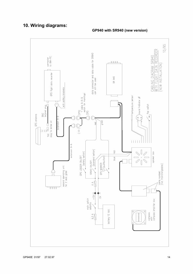
10. Wiring diagrams:GP940 with SR940 (new version)

GP940E 01/97 27.02.97 15
Wiring diagrams:GP940 with SR940 / SR820D (upgrade version)

GP940E 01/97 27.02.97 16
11. Pin assignments of connectors:

GP940E 01/97 27.02.97 17
12. Calibration chart for altimeter of GP940:
According to FAI rules an altimeter calibration chart of the recorder must be used for altitude evalua-tion of recorded flights.
If altitude differences are relevant to a claimed flight, the calibration chart must not be older than oneyear or a calibration must be done within one month after the flight. Altitude differences are importantfor all flights, where the difference between release altitude and landing altitude is not much less than1000m and for altitude gain flights. These flights are normally all aero tow flights and the 3000m /5000 m gain flights.
If absolute altitude is concerned, the calibration chart must be not older than one year and a calibrati-on must be done within one month after the flight. This is important only for absolute altitude worldrecords.
The calibration chart can be done by the manufacturer of the recorder or by any institution certified bythe national aero club.
To get an altitude trace of the GP940, the recorder must be put into a vacuum chamber and be su-plied with 12V / 170mA (minus = pin 2, plus = pin 5 of 9 pin plug at the rear of the box besides theantenna connector - see 11. Pin assignments of connectors). The GPS antenna is not connected.
When power is applied the GP940 starts recording. Now the ambient pressure is changed in stepsfrom 0m to 11000m. As the recording rate of the GP940 is one sample every four seconds, the am-bient pressure should stay enough stable at each step to get a good reading.
If it can be managed to operate the marker switch from the outside, the altitudes can be marked withone second acuracy. These marks can easily be found later in the data file for evaluation.
After all altitude steps were recorded, a PC can be connected to the 9 pin socket at the front besidesthe red light. If the internal rechargeable battery of the GP940 is charged, the power supply can bedisconnected or not. If the internal battery is empty, the power supply must be on during data transferto the PC. For data transfer use program ZANxxE.EXE or DATA-ZAN.EXE .
Flight data can be evaluated using WINDOWS program WinFDR or the flight data file *.ZAN isconverted to IGC file *.IGC . The IGC file is an ASCII file where altitude readings can be found easily.If the marker switch is used, the altitude belonging to the mark is always the last reading before themark. Each B line represents a reading:
B hhmmss ggmm.ddd N gggmm.ddd E V hhhhh ggggg iii nnn rr(hhmmss = time, hhhhh = altitude reading)

GP940E 01/97 27.02.97 18
THE FAI INTERNATIONAL GLIDING COMMISSION (IGC)GLOBAL NAVIGATION SATELLITE SYSTEM (GNSS)FLIGHT RECORDER (FR) APPROVAL COMMITTEE (GFAC)
To: FAI for distribution to NACs and IGC email & hard copy listsInternet newsgroup rec.aviation.soaring
Copy: Manufacturer concerned
10 November 1996
IGC APPROVAL FOR GNSS FLIGHT RECORDER EQUIPMENT
This document gives formal approval from the above date for the undermentioned GNSS FR equipment to beused for validation of flights under the FAI Sporting Code Section 3 (Gliders and Motor Gliders), subject to theconditions and notes given later. IGC reserves the right to alter this approval in the future.
GFAC tests are concerned primarily with data accuracy, security, downloading, and conversion to the standard*.IGC file format. Other aspects of the equipment may not be tested and are a matter between the FR manufac-turer and customers.
The attention of NACs, Officials and Pilots is drawn to theFAI Sporting Code Section 3, 1992 edition includingall amendments, particularly paragraph 1.9.2 on digital recording and 2.3.3.6. on GNSS evidence requirements.
It is recommended that a copy of this approval including its annexes is kept with each unit of the equipment.
Manufacturer: Dipl.-Ing Peter Zander, Oberdiller Strasse 38,D-82065 Baierbrunn, GERMANYTel: +49 89 79 37 890; Fax: +49 89 79 37 [email protected]
Equippment: Hardware: Version 1.16 or later of the Zander GP940 GNSS FR.Firmware: Version 1.16 or later (ie the programme inside the unit).Software: Zander file DATA-ZAN.EXE for downloading flight data from the FR and, through its menu, for con-version of each Zander format (*.ZAN) flight data file to a separate file in the *.IGC ASCII format. Also CONV-ZAN.EXE for the conversion function only. These two files are intended to be copied by NACs for use by OOson a floppy diskette without the need to access a hard disk. These files have unrestricted access and will beplaced on the IGC web server. Also, for the same purposes, for Officials familiar with the programme and me-nus concerned, Zander software release 11 dated November 1996 (ZAN11 file), or later releases. The file VALI-ZAN.EXE is for validation by NACs and FAI of the security and integrity of the *.ZAN files. The DATA, CONVand VALI files are manufacturer's copyright but are freeware.
CONDITIONS OF APPROVAL:
1 Permitted Connections to the Main (FR) Module.
1.1 To the 9-pin male socket on the GP940 body near to the antenna port: 12V external battery power and connection to the cockpit display unit.1.2 External antenna to antenna port.1.3 PC to the 9-pin female socket at the opposite end of the FR unit to the antenna port next to the red light.A PC must not be connected between the takeoff of the claimed flight and the transfer of data after flight.
2. Security of the Equipment. GFAC is presently satisfied with the physical and electronic security of thisequipment subject to para 4 overleaf on the physical security seal.
2.1 Installation in a glider: The FR may be fitted anywhere in the glider (subject to para 3.3, and 2.2 formotor gliders). If the antenna or antenna port is accessible to the crew in flight, no attempt must be made toinject data at these places; any abuse of this may lead to a future requirement to place the antenna and antennaport out of reach of the flight crew.
2.2 Installation in a motor glider (including self-sustainers): Unless the MoP is sealed (SC3 para 5.5.3.2)or inoperative (SC3 para 5.5.1/2), the FR must be firmly attached to a part of the glider structure which is ca-pable of transmitting the vibration caused by the MG means of propulsion to the case of the FR, inside which isa vibration sensor, and an engine-run must be carried out with the FR in the position used for the claimed flight,in order to prove the vibration recording system (see para A4 later).

GP940E 01/97 27.02.97 19
2.3 Sealing of data ports: no requirement, but no unauthorised data must be passed into the FR during thetime between takeoff and the start of the post-flight transfer of data by an OO. Any abuse of this may lead to afuture requirement to seal the data port. 3. Check of Installation in the Glider. Before flight, an Official Observer must check the place of the equip-ment in the glider concerned and how it is fixed to the glider. Following this examination; EITHER,
3.1. Continuous Observation. The glider must be under continuous observation by an OO until it takes offon the claimed flight (so that the FR cannot be transferred to another glider without this being seen); OR,
3.2. Sealing to the Glider. If para 3.1 cannot be met, the FR must be sealed to the glider by the OO so thatit cannot be removed without breaking the seal. The sealing method must be acceptable to the NAC and IGC.Paper seals must be marked with the glider registration, the date, time and OO's number and signature. Awire/lead or wax seal with a unique sealing die (imprint pattern) may also be used. Sealing to the glider is allo-wed to take place at any time or date in advance of the flight. This is because all GNSS fixes have a date/timecontent, unlike a drum-type barograph. The use of adhesive plastic tape is not satisfactory for IGC-approvedsealing because it can be peeled off and re-fitted. Gummed paper tape is recommended, as used for sealingdrum-type barographs.
3.3. Place of Installation in the Glider. See para 2.1. Where sealing to the glider is required under para3.2, the OO must seal the FR unit to glider parts which are part of the minimum standard for flight. It is accep-ted that such parts can be removed for purposes such as servicing; such parts include the canopy frame, in-strument panel, and centre-section bulkhead fittings. If such a part is transferred between gliders, any FRseal for the previous glider must be removed. For motor gliders, see para 2.2.
4. Security Seals, Physical and Electronic. The FR unit is physically sealed with adhesive security tape ac-ross the bottom of the case. An internal electronic security mechanism is also included and its security checkwill no longer work is the case is opened. If the FR is found to be unsealed electronically, it must be returned tothe manufacturer or his appointed agent for investigation and resealing, with a statement of how the unit beca-me unsealed. Whenever any unit is resealed, the manufacturer or agent must carry out positive checks on theinternal programmes and wiring, and ensure that they work normally. If any evidence is found of tampering orunauthorised modification, a report must be made by the manufacturer or agent to the Chairman of GFAC andto the NAC of the owner; the IGC approval of that individual unit will be withdrawn until the unit is re-set andcertified to be to the IGC-approved standard.
5 After-Flight Transfer of Flight Data from the FR and conversion to *.IGC File Format. Only the IGC-approved standard of software shall be used. This standard is given on page 1 under `Equipment', and `soft-ware'.
6 Analysis of Flight Data. Analysis of flight data may be through any analysis programme which is approvedby the relevant NAC such as those which use the *.IGC file format. The *.ZAN file which was originally downlo-aded from the FR must be checked as unaltered by the NAC by the use of an authenticated version of the VA-LI-ZAN.EXE file (see page 1 under "software"), and the CONV-ZAN.EXE programme then used to derive the*.IGC file from it; this newly-created *.IGC file must either be used for flight analysis or be checked as beingidentical to any earlier version of the *.IGC format which may have been used for preliminary analysis.
7 Manufacturer's Changes. Notification of any intended change to hardware, firmware or software must bemade by the manufacturer to the Chairman of GFAC so that a decision can be made on any further testingwhich may be required. Ian StrachanChairman, IGC GFAC10 Nov 1996
Annexes: A. Notes for owners and pilots B. Notes for Official Observers and NACs
Any Queries to:Chairman IGC GFAC, Bentworth Hall West, Alton, Hampshire GU34 5LA, EnglandTel: +44 1420 564 195; Fax: +44 1420 563 140; email: [email protected] A to IGC Approval Dated 10 Nov 1996
NOTES FOR OWNERS AND PILOTS -PART OF IGC APPROVAL FOR ZANDER GP 940 GNSS FR

GP940E 01/97 27.02.97 20
To be read together with the main terms of approval to which this is an Annex. It is recommended that a copyof the approval document including annexes is kept with the equipment concerned, for the use of pilots andOfficial Observers.
Pilot's Responsibility. It is the responsibility of the pilot to ensure or to note the following:
A1 Signal Strength - That the antenna is positioned in order to give sufficient signal strength for IGC purposes.No deliberate attempt must be made to inject data via the antenna or antenna port; any abuse of this may leadto a future requirement to position antennas and the antenna port out of reach of the flight crew. Note that testsshow that carbon fibre skins covering some centre-sections attenuate the 1.5 GHz GPS signal, and also thatproximity to some metal fittings can also attenuate the signal.
A2 Geodetic Datum. The FR has a fixed Geodetic datum of WGS84. Any start, turn, and finish, points mustbe entered with lat/longs which are to this datum. PC-based conversions such as the US DMA MADTRAN pro-gramme (non-copyright) are available from NACs and FAI. Other datum transformation programmes are avai-lable from commercial software sources.
A3 Connection to Ports. Although this approval does not presently require sealing of any ports, no unauthori-sed data must be passed through any port during the time between takeoff and the start of the post-flight trans-fer of data by an OO. See para 2.3 in the conditions of approval on page 2.
A4 Use in Motor Gliders (including self-sustainers): A vibration sensor is built in to the FR unit and attachedto the inside of the case, and must be used for checking the use of the Means-of-Propulsion (MoP), unless theMoP is sealed (SC3 para 5.5.3.2) or inoperative (SC3 para 5.5.1/2).
A4.1 Use of vibration sensor for MoP recording. The FR unit must be firmly attached to a part of the gliderstructure which is capable of transmitting the vibration caused by the MoP to the case of the FR. The FR mustbe sealed to the glider (para 3.2 on page 1 applies) unless the FR is out of each of the flight crew and an enginerun is carried out during the flight to prove the recording system. Where the FR is sealed by an OO to theglider structure, the engine-run which proves the system may be carried out at any time between sealing andunsealing the FR. It is understood that the manufacturer is designing a microphone-based system which, aftersuccessful testing, may allow the above restrictions to be withdrawn.
A5 After Flight - The pilot should ensure that the time and point of landing has been witnessed and recorded forcomparison with that recorded by the GNSS FR. Until an OO has witnessed the FR fit (installation) to the gliderand either downloaded the flight data or removed the FR for downloading, the pilot must not alter the FR instal-lation to the glider. The OO will carry out the actions given in Annex B, and the downloaded flight data will bekept secure to the OO and to NAC-approved persons only; the pilot may request a copy of the downloaded data.
A6 Calibration of Barograph Function. Pilots are advised to have a barograph calibration carried out eitherby the manufacturer or by an NAC-approved calibrator before any GNSS FR is used for a claimed flight perfor-mance. Altitude and height claims require a calibration for the flight performance concerned, and speed anddistance claims need a calibration in order that the altitude difference between the departure and finish pointsmay be calculated. All claims require that (calibrated) FR takeoff and landing pressure altitudes are comparedwith the separately-recorded QNH pressures. See Annex B para B5, and the Sporting Code for gliders, particu-larly para 2.2.1.1.
A7 Entering Lat/Longs for turn points and flight declarations. Note that lat/longs can only be entered asdegrees, minutes and seconds, there is no option at present for decimal minutes to be used.
--------------------------------------------

GP940E 01/97 27.02.97 21
Annex B to IGC Approval Dated 10 Nov 1996
NOTES FOR OFFICIAL OBSERVERS AND NACs -PART OF IGC APPROVAL FOR ZANDER GP 940 GNSS FR
To be read together with the main terms of approval to which this is an Annex. It is recommended that a copyof this approval document is kept with the equipment concerned, for the use of pilots and Official Observers.
B1. Checks before Flight.
B1.1. Glider Installation of the FR. An OO shall inspect the installation of the FR in the glider before flightand shall note the position in the glider, the serial number of the FR, glider registration, date and time. If theglider cannot then be observed continuously by the OO until it takes off on the flight concerned, the OO shallseal the FR to the glider in a way acceptable to his NAC and to IGC (see paras 2 and 3 of the Conditions ofApproval given earlier on pages 1 and 2). B1.2. At Takeoff. The time and point of takeoff shall be recorded, either directly by the OO, other witnesses, orby other means such as an Air Traffic Control or Club log of takeoffs and landings. The local barometric pres-sure (QNH) shall either be noted or obtained later from a local meteorological office so that this can be compa-red later with the pressure altitude on the flight data file.
B2. As Soon as Practicable After Landing.
B2.1. At Landing. The time and exact point of landing shall be recorded, either by an OO, other witnesses(SC3 para 2.2.11.5 (b) (2)), or by other means such as an Air Traffic Control or official Club log of takeoffsand landings. The local barometric pressure shall either be noted or obtained later from a local meteorologi-cal office for the time of landing so that this can be compared later with the pressure altitude onthe flight data file.
B2.2. Checking the Installation of the FR. As soon as practicable after landing, an OO shall inspect theinstallation of the FR in the glider (including any sealing to the glider), so that this can be compared to the pre-flight check described in para B1.1 above.
B2.3. Downloading the Flight Data. If a portable PC is available, the flight data may be transferred at the gli-der without disturbing the installation of the FR; if a portable PC is not available, the OO shall check and breakany sealing to the glider, and personally take the main FR module to a PC. Connect the PC to the main FRmodule's 9-pin data port, and use either the download file DATA-ZAN.EXE on a floppy diskette (see under`software' on page 1), or use the manufacturer's full PC programme, following the instructions given in the me-nu. The floppy disk may be self-booting and may have a short menu with instructions for the OO to follow. Itmust have originated from an authorised source such as an NAC or someone approved by an NAC. This pro-cess will produce a binary-format flight data file *.ZAN, which shall be on or copied to a diskette signed by theOO, and retained in safe keeping for later checking and analysis. The diskette shall originally either be blank ormay be the one which contained the DATA-ZAN.EXE files for downloading. Another diskette with the downloa-ded *.ZAN flight file copied on it shall be given to the pilot on request, at this or a later time when convenient.
B.3. Analysis of Flight Data Files
B3.1. Conversion to *.igc File Format. After landing or at a future time, an OO or an NAC-approved dataanalyst must use the approved software to convert the binary *.ZAN file to the *.IGC file format. This is throughthe menu in the DATA-ZAN.EXE file, through the CONV-ZAN.EXE file, or the full ZAN11E/D.EXE (or later) pro-gramme, see Page 1 under "software"; if using the CONV file, after CONV-ZAN, type a space followed by thefull file name to be converted, followed by ENTER. Note that the original *.ZAN file remains and the *.IGC file isin addition. B3.2. Flight Data Analysis. A Data Analyst approved by the NAC can then commence the flight analysis u-sing an analysis programme approved by the NAC concerned. In addition to checking flight data, an authenti-cated version of the file VALI-ZAN.EXE shall be used by the NAC and/or FAI (if the data goes to them) to checkthat the flight data in the *.ZAN and *.IGC files has not been altered; type VALI-ZAN.EXE followed by a spaceand the name of the file to be checked. The message "Security Check OK" should appear, not "Security CheckNot OK (or "Electronic seal faulty"), Flight Data Invalid".
B4. Means of Propulsion (MoP) Record - Motor Gliders. The MoP must either be sealed (SC3 para5.5.3.2) or inoperative (SC3 para 5.5.1/2), or the vibration recording system used in accordance with para A4.1.
GP940E 01/97 27.02.97 22
An ENL (Engine Noise Level) value of over 250 indicates engine running or the vibration of takeoff or landing.Consistently lower ENL values indicate gliding flight.
B5 Calibration of Barograph Function. The FR can be calibrated in an altitude chamber in the same wayas a drum barograph. After the calibration, the data is downloaded as if it was flight data (see B2.3 above) andthe calibration data file will then be analysed and a correction table produced of true against indicated altitudes.This table can then be used to correct pressure altitudes which are recorded during flight performances andwhich require correction for validation to IGC criteria. These include takeoff, start and landing altitudes for alti-tude difference and for comparison with QNH readings, and low and high points on gain-of-height and altitudeclaims. The maximum height tested by GFAC (Sep 96) was 50,000 ft.
----------------------------------------------