ex press 4 is so easy 2017 - startseite - zander … · 2 ex_press 4 is so easy zander gmbh &...
TRANSCRIPT

Operating Instructions
A programming course for the PLC language
Structured Text according to IEC 61131-3
EX_PRESS 4 is so easy

2
EX_PRESS 4 is so easy
Zander GmbH & Co. KG
Am Gut Wolf 15
52070 Aachen, Germany
www.zander-aachen.de
Issue: J2
English Translation.
Subject to technical modifications; no responsibility
is accepted for the accuracy of this information.
EX_PRESS 4 is so easy!
A programming course for the PLC language
Structured Text according to IEC 61131-3
By Dipl.-Ing. Alfons Austerhoff
This short programming guide provides a quick and easy entry to the programming of the ZANDER controllers EX16 and SPEEDY with the help of many practical and easy comprehensible examples. It teaches the essential knowledge of the PLC programming language „Structured Text“. Further information provides the online help of the programming software EX_PRESS 4. © 1999, 2012, 2017 by H. ZANDER GmbH & Co. KG, Am Gut Wolf 15, 52070 Aachen No part of this manual may be copied, in any way, without written approval from ZANDER GmbH & Co. KG. The contents has been drawn up with the greatest possible care, but no guarantee can be assumed of it being free from mistakes or for damages which arise from the use of this documentation. This documentation is based on EX_PRESS 4 V4.4, February 2017.

3
EX_PRESS 4 is so easy
Content
1. Installation ...................................................................................4
2. Program Structure .......................................................................4
3. The first Program with EX_PRESS 4..........................................6
3.1 Select PLC-Type.........................................................................10
3.2 Compilation and Fitting ............................................................10
3.3 Download the Program into the PLC .......................................12
4. Logical Operators NOT, AND, OR, XOR ...................................14
5. Self-retaining ................................................................................15
6. Register ........................................................................................16
7. Timer ............................................................................................17
8. Internal Variables .........................................................................19
9. IF Instruction ................................................................................20
10. Arrays .........................................................................................21
11. Relational Operators..................................................................21
12. CASE Instruction .......................................................................22
13. Online Help, Sample Programs ................................................23
Annex 1. Commands and Keywords of the EX_PRESS 4 ...........24
Annex 2. Program Capacity of the CPLD .....................................25
Annex 3. FAQ ..................................................................................26
Annex 4. EX_PRESS 4 Troubleshooting ......................................27

4
EX_PRESS 4 is so easy
1. Installation
EX_PRESS 4 is designed for the operating systems Windows XP, 7, 8.1,10
(32 or 64 bit).
For the EX_PRESS installation please connect the USB stick with your
computer. Start the setup program (EX_PRESS_Setup_en2.exe - english
language, EX_PRESS_Setup_de1.exe - german language) with the
Windows Explorer or with the Function „Run“ in the start menu (Task Bar).
Please follow the instructions.
Attention: A parallel installation of both languages (EX_PRESS_en2.exe,
EX_PRESS_de1.exe) is possible. Uninstalling the first installed version will
not affect the other, but uninstalling the latest version will prevent the
remaining version from proper operation. Example: You are installing
EX_PRESS_Setup_de1.exe (german language) first followed by the
installation of EX_PRESS_Setup_en2.exe (english language). After the
uninstalling of EX_PRESS 4e, the remaining version of EX_PRESS 4d will
not work´and must be reinstalled.
2. Program Structure
Each EX_PRESS 4 program has the following general structure (see Fig. 1):
Fig. 1: Program Structure

5
EX_PRESS 4 is so easy
The program parts printed in bold type are mandatory, the
others are optional (depending on the project/application).
The bold marked parts of the program are necessary for each program. The
other program parts are optionally depending on the individual application/
project (optional).
The following „case study“ explains each program steps. We recommend to
run each program step on your computer with your EX_PRESS 4 version.
As a first step open EX_PRESS 4 with the start menu/task bar. You see an
empty text editor, in which you can realize your first program. Open the editor
by using the menu “File“, „New“ (see Fig. 2).
In this document the program code is visualized in italic!
Fig. 2: New Program File

6
EX_PRESS 4 is so easy
3. The first Program with EX_PRESS 4
The first step is to describe the application. In this example a simple motor
controller will be programmed. Three inputs and three outputs of the PLC are
required for the application (Fig. 3):
Description of the Application:
1) The motor has to run when the switch Start is closed
2) If the input signal (E2) is activated, the motor must stop.
3) If the output Alarm (A2) is getting a signal, the motor has to stop too.
4) The output Alarm (A2) should be inverted to the fault indication unit (E3).
→ Alarm should switch on when the fault indication signal falls to off state.
5) The warning light (A3) should be on when Alarm is on and also the start
switch is closed.
Comments Section
This program part is optional, but highly recommended. Here you have the
possibility to describe the function, document the version, document the date
of preparation or any other hints are possible.
This is the first EX_PRESS-Programm. It contains everything to run a full functional control application for EX16 and all SPEEDY PLC´s. Last Change: 06.12.2016 Version: 2.16 Author: Dipl.-Ing. Alfons Austerhoff, H. ZANDER GmbH & Co. KG, Aachen
Motor
Alarm
A3
0
1
STOP
Störmelde-
einrichtung
Start
Stop
E3 Fault indication
E1
E2
A1
A2
Fig. 3: First Application
7
EX_PRESS 4 is so easy
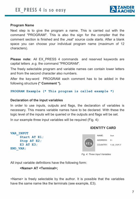
Program Name
Next step is to give the program a name. This is carried out with the
command "PROGRAM". This is also the sign for the compiler that the
comment section is finished and the „real“ source code starts. After a blank
space you can choose your individual program name (maximum of 12
characters).
Please note: All EX_PRESS 4 commands and reserved keywords are
capital letters ,e.g. the command "PROGRAM".
The freely selectable program and variable names can contain lower letters
and from the second character also numbers.
After the key-word PROGRAM each comment has to be added in the
following structure (* Comment *).
PROGRAM Example (* This program is called example *)
Declaration of the input variables
In order to use inputs, outputs and flags, the declaration of variables is
necessary. This means variable names have to be declared. With these the
logic level of the inputs will be queried or the outputs and flags will be set.
In our example three input variables will be required (Fig. 4):
VAR_INPUT Start AT E1; Stop AT E2; E3 AT E3; END_VAR;
All input variable definitions have the following form:
<Name> AT <Terminal>;
<Name> is freely selectable by the author. It is possible that the variables
have the same name like the terminals (see example, E3).
IDENTITY CARD
NAME: Start
ADDRESS: E1
COUNTRY: VAR_INPUT
STA
Fig. 4: Three Input Variables

8
EX_PRESS 4 is so easy
<Terminal> always defines the connection of a variable to the input terminals
E1 up to E16 (PLC type Speedy ZX8: E1 up to E9).
Attention: Each line has to be terminated by a semicolon. This also applies
for the last line after the command END_VAR.
Declaration of the Ouput Variables
The declaration of the output variables is similar to the input variables.
<Name> AT <Terminal>;
The <Name> is freely selectable by the author. <Terminal> defines the
connection to an output terminal A1 to A16 (Speedy A1 up to A8).
VAR_OUTPUT Motor AT A1; Alarm AT A2; A3 AT A3; END_VAR;
The declaration of internal variables and arrays will be discussed later.
These are only necessary for some special applications.
Statement Part
Regarding the first program. After all input and output variables have been
declared the next step is the statement part of the program. In this part, the
functions of the PLC will be realized. A logical state has to be assigned to
each output variable. This is carried out by the following equation:
<Output variable> := <Logical expression>;
<Output variable> is a declared name in the program part VAR_OUTPUT,
the symbol := is an assignment operator, <Logical expression> consists of a
combination of declared variable names and logical operations AND, OR,
XOR and NOT.
The sequence of the assignments is freely selectable due to a parallel
processing of all signals. Therefore A3 is programmed first, followed by the

9
EX_PRESS 4 is so easy
motor and at the end the alarm is programmed in this example.
Attention: Comparable to the variables, each assignment (each line) has to
be finished by a semicolon.
A3 := Alarm AND Start; Motor := Start AND NOT Stop AND NOT Alarm; Alarm := NOT E3;
The first EX_PRESS 4 program is finished. Last step is the command that
the program is finished.
END_PROGRAM;
For the next steps, your program has to be saved on a harddisk. Press the
menu item “File“ (Fig. 5) followed by “Save“. You will see a new window in
which you can choose the program name. Our choice is “Example.s16“.
By pressing the menu „File“ followed by „Open ...“ you will find further
application examples in Structured Text, which are sorted according to the
Zander PLC types (EX16 / SPEEDY ZX4T, ZX4TE, ZX8T). The programs
counter, conveyer, etc. are stored in the installation path.
The default installation path is:
C:\Zander\EX_PRESS4e\ExamplesEX_PRESS.
Fig. 5: Menu Item „File“

10
EX_PRESS 4 is so easy
3.1 Select PLC Type
The PLC-Type Menu is included inside the Main Menu and contains the
following items:
• EX16
• SPEEDY (ZX4T, ZX4TE, ZX8T)
EX_PRESS 4 supports these Programmable Logic Controls. You have to
select one of these items in order to use the actual PLC you want to program;
afterwards the actual selection is shown by a tick item (a). See Fig. 6.
The so-called E-type distinguishes between different variants of the used
CPLD. For EX16, and ZX8 relay type the tick should always be cleared, while
for the SPEEDY-Family ZX8T and ZX4T/TE it should always be set.
The PLC type affects both compiling and programming. If programming fails,
please toggle the tick for the E-Type and re-compile and re-program the code
into the PLC. This should fix the problem.
3.2 Compilation and Fitting
The program has to be transferred into a structure, which is compatible to the
programmable logic parts of the PLC. This is realized in two steps.
In a first step the compiler translates the Structured Text (ST) program into a
boolean code. The result is a logical intermediate code. Following this, the
fitter can be started. This process generates the so called „Jedec-Code“. This
code can be transfered into your PLC (Speedy, EX16).
Fig. 6: Select PLC type
11
EX_PRESS 4 is so easy
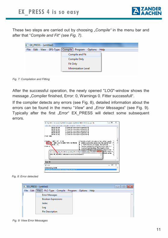
These two steps are carried out by choosing „Compile“ in the menu bar and
after that “Compile and Fit“ (see Fig. 7).
After the successful operation, the newly opened "LOG"-window shows the
message „Compiler finished, Error: 0, Warnings 0. Fitter successfull“.
If the compiler detects any errors (see Fig. 8), detailed information about the
errors can be found in the menu “View“ and „Error Messages“ (see Fig. 9).
Typically after the first „Error“ EX_PRESS will detect some subsequent
errors.
Fig. 7: Compilation and Fitting
Fig. 9: View Error Messages
Fig. 8: Error detected
12
EX_PRESS 4 is so easy
The user should correct the first error in the list. After that the whole program
should be compiled and fitted again.
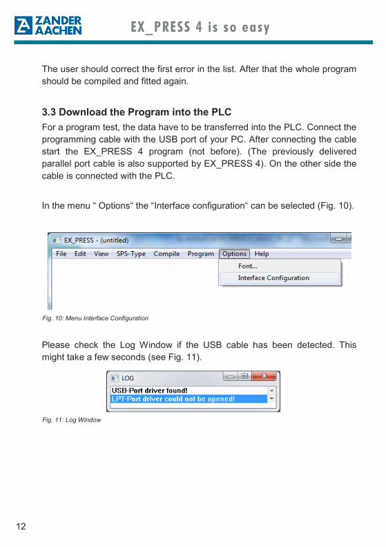
3.3 Download the Program into the PLC
For a program test, the data have to be transferred into the PLC. Connect the
programming cable with the USB port of your PC. After connecting the cable
start the EX_PRESS 4 program (not before). (The previously delivered
parallel port cable is also supported by EX_PRESS 4). On the other side the
cable is connected with the PLC.
In the menu “ Options“ the “Interface configuration“ can be selected (Fig. 10).
Please check the Log Window if the USB cable has been detected. This
might take a few seconds (see Fig. 11).
Fig. 10: Menu Interface Configuration
Fig. 11: Log Window

13
EX_PRESS 4 is so easy
After applying the supply voltage the program can be transmitted by
choosing “Download to:“ in the menu „Program“ (see Fig. 12).
The first EX_PRESS 4 program is finished. We can now check the
functionality of the program by the input and output LED of the PLC.
Comparable to these example you can realize a lot of applications.
The next chapters contain further logic operations and if– and case-
assignments.
Fig. 12: Download the program into the PLC

14
EX_PRESS 4 is so easy
4. Logical Operators NOT, AND, OR, XOR
All logical control tasks can be achieved with the logical operators NOT,
AND, OR und XOR. The following diagrams show for each operater type a
graphical function block, the truth table and the syntax in Structured Text.
1E1 A1 E1 A1
0 1
1 0
A1 := NOT E1;
&E1 A1
E2
E1 E2 A1
0 0 0
0 1 0
1 0 0
1 1 1
A1 := E1 AND E2
NOT
AND
>1E1 A1
E2
E1 E2 A1
0 0 0
0 1 1
1 0 1
1 1 1
A1 := E1 OR E2;
=1E1 A1
E2
E1 E2 A1
0 0 0
0 1 1
1 0 1
1 1 0
A1 := E1 XOR E2;
OR
XOR
Fig. 13: Logical Operators

15
EX_PRESS 4 is so easy
If a drawing in the form of logical symbols exists, then it is easy to convert it
into Structured Text . Care must be taken that all input signals belonging to a
logical symbol are grouped by using brackets to preserve the sequence of
operations and the priorities. (see Fig. 14).
5. Self-retaining
In the example program a motor was switched on by activating the input
„Start“. As soon as the signal is no longer present, the motor switches off. It
would be more convenient to switch on the motor by pressing a button
„Start“, and to switch it off by pressing a button „Stop“. To achieve this, the
following changes are necessary in the example program:
The input variable POR (=Power-On-Reset) is added to the declaration:
VAR_INPUT
... POR AT POR; END_VAR;
The signal POR is a power-on / reset signal by a specific on-board hardware
circuit, which will be active for approx. 200 ms after the supply voltage has
been switched on.
1
A1
1
E1&
&
>1
>1
E2
E3
E4
E5
A1 := ((E1 AND NOT E2) OR (E3 AND E4)) OR NOT E5;
Fig. 14: Input signals grouped together

16
EX_PRESS 4 is so easy
This is required to assure that the output „Motor“ does not inadvertently goes
into self-retaining, because the signal level is briefly undefined during the
power-on.
For obtaining the self-retaining, the assignment for „Motor“ has to be
extended with the following program line:
If the start button is switched on, the part before the OR is true, so the motor
switches on. As soon as this happens, the part behind the OR will become
true too, so that the motor continues to run, even if the start button is
released. Only pressing the Stop button or the activation of the output
„Alarm“ cause the part behind the OR to become logically 0 and the motor
switches off. The self-retaining can only be activated by inserting „AND NOT
POR" if the power-on reset signal falls to 0.
6. Register
In addition to the described AND-, OR- and XOR-gates the programmable
logic module of the EX16 or SPEEDY has additional registers, which can
store logical conditions. This function is easily recognized in the following
diagram (Fig. 15):
Using registers with EX_PRESS 4 is performed by the command
<Variable>.CLK := <clock signal>;
E A
Takt
Reset
Takt
E
Reset
A
Clock
Clock
Fig. 15: Register
Motor := Start AND NOT Stop AND NOT Alarm OR Motor AND NOT Stop AND NOT Alarm AND NOT POR;

17
EX_PRESS 4 is so easy
The logic value at the input of the register is then stored at the output at any
positive edge (transition from 0 to 1) of the clock signal. If required, registers
can be reset asynchronously by a signal connected to the reset input.
Asynchronously means that the reset to 0 is spontaneously done without any
edge at the clock signal.
<Variable>.RE := <reset signal>;
The following example generates exactly the output signal which is shown in
the diagramm:
Program for the explanation of the registers PROGRAM Register VAR_INPUT E AT E1; Clock AT T1; Reset AT E2; END_VAR; VAR_OUTPUT A AT A1; END_VAR; A.CLK := Clock; (* With this line, the output becomes
a register *) A.RE := Reset; (* Assignment of the asynchron Reset *) A := E; (* logic input of the registers *) END_PROGRAM;
7. Timer
In the program "Register" the timer T1 was used as a clock generator.
Unless otherwise specified, the time laps begin when the operating voltage is
applied, however there is also the possibility to start and stop it by the
program: Via the reset inputs (see picture) the timer can be started (Low) or
stopped (High).
18
EX_PRESS 4 is so easy
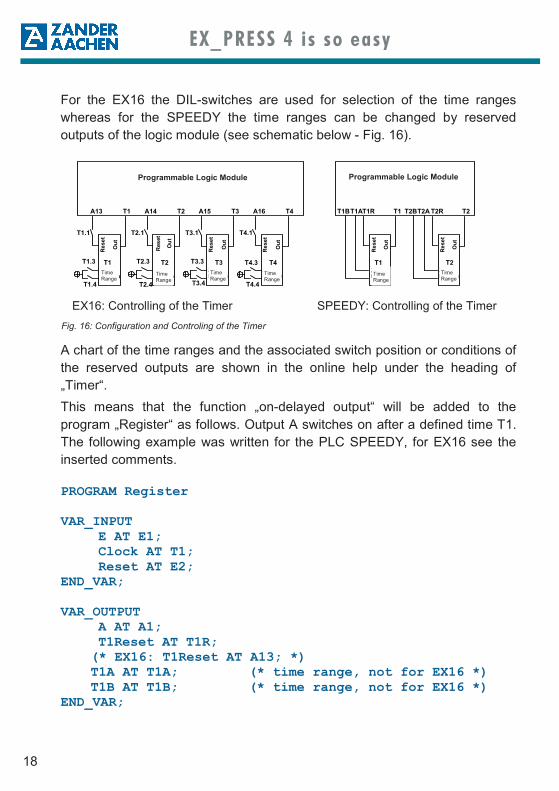
For the EX16 the DIL-switches are used for selection of the time ranges
whereas for the SPEEDY the time ranges can be changed by reserved
outputs of the logic module (see schematic below - Fig. 16).
A chart of the time ranges and the associated switch position or conditions of
the reserved outputs are shown in the online help under the heading of
„Timer“.
This means that the function „on-delayed output“ will be added to the
program „Register“ as follows. Output A switches on after a defined time T1.
The following example was written for the PLC SPEEDY, for EX16 see the
inserted comments.
PROGRAM Register VAR_INPUT E AT E1; Clock AT T1; Reset AT E2; END_VAR; VAR_OUTPUT A AT A1; T1Reset AT T1R; (* EX16: T1Reset AT A13; *) T1A AT T1A; (* time range, not for EX16 *) T1B AT T1B; (* time range, not for EX16 *) END_VAR;
EX16: Controlling of the Timer SPEEDY: Controlling of the Timer
Res
et
Ou
t
A13 T1 A14 T2 A15 T3 A16 T4
Re
se
t
Ou
t
Re
se
t
Ou
t
Re
se
t
Ou
t
T1.1 T2.1 T3.1 T4.1
T1 T2 T3 T4Zeit-bereich
Zeit-bereich
Zeit-bereich
Zeit-bereich
T1.3 T2.3
T1.4 T2.4
T3.3
T3.4
T4.3
T4.4
Programmierbarer Logikbaustein
T1R T1 T2R T2
Re
se
t
Ou
t
Re
se
t
Ou
t
T1 T2Zeit-bereich
Zeit-bereich
Programmierbarer Logikbaustein
T2AT2BT1BT1A
Programmable Logic Module Programmable Logic Module
Time
Range Time
Range Time
Range Time
Range Time
Range Time
Range
Fig. 16: Configuration and Controling of the Timer

19
EX_PRESS 4 is so easy
8. Internal Variables
The programmable logic modules of the PLC´s EX16 and SPEEDY have 44
1-bit registers, which are not connected to any input or output. This can be
used to buffer logical status signals, e.g. if a short pulse is present at an
input.
Internal variables are defined in the declaration part "VAR_INTERN" and
contain just a name, not a location. They behave like output variables, so
they can be defined asynchronously (output of a logical gate) or with
the .CLK-extension as a register.
In the above shown example an internal variable can be used to bridge the
gap between applying the input signal „E“ and the output „A“ switches, so
that only a short impulse at the input „E“ is necessary. Since a self-retaining
should be programmed the input variable „POR“ (Power-On-Reset) must be
defined.
VAR_INPUT
... POR AT POR; END_VAR; VAR_INTERN M; END_VAR; M := E (* switch-on condition *) OR M AND NOT A AND NOT POR; (* self-retaining with Switch-off condition *)
A.CLK := Clock; (* With this line the output becomes a register *)
A.RE := Reset; (* Assignment of the asynchronical reset *) A := 1; (* A switches on after time T1 (=clock),
because the logic signal 1 is always at the logic input of the register. The switching off is performed by Reset *)
T1Reset := NOT E; (* T1Reset changes to 0, if E becomes active, and therefore Timer T1 runs*)
END_PROGRAM;

20
EX_PRESS 4 is so easy
The assignment equation "T1Reset := NOT E;" is replaced by:
T1Reset := NOT M;
9. IF Instruction
The program language "Structured Text" features some program constructs
which provides a good program oversight and makes it easier to read the
program.
One of them ist the IF instruction which separates visually logical conditions
and instructions and which has a greater functionality than the before
introduced logical equations. The form of the IF instruction is as follows:
IF ( <condition> ) THEN
<assignment(s);>
ELSIF ( <condition> ) THEN
<assignment(s);>
ELSE
<assignment(s);>
ENDIF;
The assignment "ELSIF" and "ELSE" are opional and therefore not printed in
bold characters.
Example:
PROGRAM IF_Anw VAR_INPUT E1 AT E1; E2 AT E2; E3 AT E3; E4 AT E4; END_VAR;

21
EX_PRESS 4 is so easy
VAR_OUTPUT A1 AT A1; A2 AT A2; A3 AT A3; A4 AT A4; A5 AT A5; A6 AT A6; END_VAR; IF (E1 AND (E2 XOR E3) OR NOT E4) THEN A1 := 1; A3 := 1; ELSIF (NOT (E2 XOR E3)) THEN A2 := 1; A5 := 1; ELSE A4 := 1; A6 := 1; END_IF; END_PROGRAM;
10. Arrays
EX_PRESS 4 offers the possibility to combine several 1-bit variables into one
multi-bit (max. 8 Bit). This is done in the declaration part by:
VAR_ARRAY
<NAME> [<Var1>, <Var2, ... ];
END_VAR;
<Var1>, <Var2> etc. must be previously declared as variables. <VAR1> is
the most significant bit.
11. Rational Operators
With the rational operators =, >, <, >=, <= and <> it is possible to carry out
logical comparisons of an array with a fixed value, but also of 1-bit variables
with 0 or 1.
22
EX_PRESS 4 is so easy
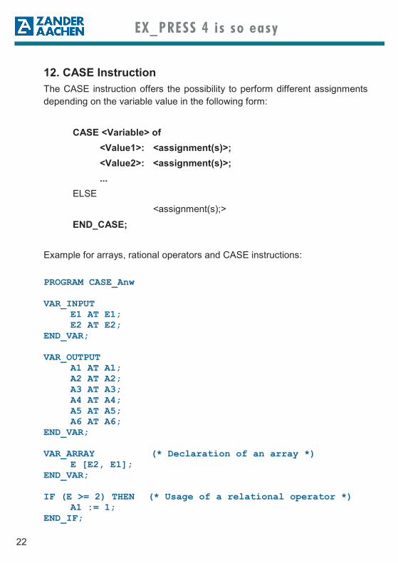
12. CASE Instruction
The CASE instruction offers the possibility to perform different assignments
depending on the variable value in the following form:
CASE <Variable> of
<Value1>: <assignment(s)>;
<Value2>: <assignment(s)>;
...
ELSE
<assignment(s);>
END_CASE;
Example for arrays, rational operators and CASE instructions:
PROGRAM CASE_Anw VAR_INPUT E1 AT E1; E2 AT E2; END_VAR; VAR_OUTPUT A1 AT A1; A2 AT A2; A3 AT A3; A4 AT A4; A5 AT A5; A6 AT A6; END_VAR; VAR_ARRAY (* Declaration of an array *) E [E2, E1]; END_VAR; IF (E >= 2) THEN (* Usage of a relational operator *) A1 := 1; END_IF;

23
EX_PRESS 4 is so easy
CASE E OF (* CASE instruction*) 0: A2 := 1; 1: A3 := 1; A4 := 1; 2: A2 := 1; A5 := 1; 3: A6 := 1; END_CASE; END_PROGRAM;
13. Online Help, Program Examples
This document contains a first introduction into the language ST-16 and the
use of the features of PLCs for applications.
For more detailed information, please use the online help, which is provided
with the Software EX-PRESS 4.
Also you will find more program examples in ST (see page 9).

24
EX_PRESS 4 is so easy
Annex 1 – Commands and keywords of EX_PRESS Keyword Function, Meaning Chapter of the online help (Menu “Help”, Function “Content”,
“Introduction into the language ST-16”)
AND, & ___________Logical AND operation _______________ Allocation and logical operators
CASE...OF..._______Multiple branching, -case distinction _____ Program constructs
ELSE_____________Alternative for CASE or IF_____________ Program constructs
ELSIF...THEN______Alternative condition for IF ____________ Program constructs
ENDIF____________End of IF-query _____________________ Program constructs
END_CASE _______End of CASE-branching ______________ Program constructs
END_PROGRAM ___End of programm source code _________ General Structured Text
END_VAR_________End of variable declaration ____________ Variables– and name conventions
IF...THEN...________Branching, case distinction ____________ Program constructs
NOT, -____________Logical negation ____________________ Allocations and logical operators
OR ______________Logical OR-combination ______________ Allocations and logical operators
PROGRAM ________Start of the programm source code______ General Structured Text
VAR_ARRAY ______Declaration of multibit-variables ________ Variables– and name conventions
VAR_INPUT...AT...__Declaration of input variables __________ Variables– and name conventions
VAR_INTERN______Declaration of registers and flags _______ Variables– and name conventions
VAR_OUTPUT...AT... Declaration of output variables _________ Variables– and name conventions
XOR _____________Logical anticoincidence-linking _________ Allocations and logical operators
.CLK _____________Definition of a register variable _________ Properties of variables
.CRIT ____________Definition of a time sensitive Signal _____ Properties of variables
.OE ______________Deactivating of a output variable________ Properties of variables
.RE ______________Reset input for register variable ________ Properties of variables
:=________________Assignment operator_________________ Allocations and logical operators
= ________________Relational operator: equal_____________ Allocations and logical operators
<> _______________Relational operator: different___________ Allocations and logical operators
< ________________Relational operator: less than __________ Allocations and logical operators
<= _______________Relational operator: less than or equal ___ Allocations and logical operators
> ________________Relational operator: more than _________ Allocations and logical operators
>= _______________Relational operator: more than or equal __ Allocations and logical operators
(...) ______________Change of evaluation priorisation _______ Allocations and logical operators
(*...*) _____________Comment__________________________ General Structured Text

25
EX_PRESS 4 is so easy
Annex 2 – Program Capacity of the CPLD
The programmable logic device of the PLC EX16 or SPEEDY possesses a
total of 96 registers, 36 of those are directly assigned to the inputs and
outputs. From the remaining 60 registers, always one is required for each
defined output. The rest can be used in the program as registers, flags,
counting variables etc.
Within the CPLD 300 OR and 5000 AND gates are available. Each signal
can individually be inverted. These variables are arranged as logic blocks in
and can be connected by a connection matrix.
Practice shows that the limiting factor of the program capacity is not the
amount of available logic modules but the amount of inputs and outputs per
logic block. The fitter software takes care of the assignment of the logic
function to the logic modules as well as the wiring of the modules
to each other or the inputs and outputs and optimises as far as possible.
To estimate the required resources within the CPLD for a particular program
it is noted that besides the directly programmed logic and registry functions
additonal logic might be required as linking help; so there will be some
“ glue logic - waste “. Thereby: The more complex the equations are, the
higher the waste; 20% can be assumed as an average value.

26
EX_PRESS 4 is so easy
Annex 3 – Frequently Asked Questions
How large is the program memory of the EX16/Speedy?
You cannot measure the storage capacity in kByte as with a microcontroller,
because the programming is converted into hard-wired logic.
Therefore a statement can only be issued about the numbers of logical gates
and the number of the available electrical wires within the programmable
logic module (see Annex 2).
How many times can the EX16/Speedy be reprogrammed?
The manufacturer of the programmable logic device ensures a minimum of
1000 write cycles.
Which operating system is necessary for EX_PRESS 4?
Windows XP, 7, 8.1, 10 (32 or 64 Bit)
Can times be programmed by software?
The logic device does not have internal timers, therefore one of the timer
signals T1 - T4. SPEEDY provides a calibrated time base of 100 ms at the
left stop of the potentiometer.
By programming of a counter a clock can be scaled down. By using one
clock signal several timing intervals can be generated.
An example for the programming of a timer can be found in the online help
under the menu item „Introducing the Structured Test Syntax“, subitem
„one example explained in detail“. With the variables Z1 to Z4 a 4-Bit-timer
was programmed.
How many flags are available?
There is a minimum of 44 1-Bit-registers available.
See also Annex 2 - Program Capacity of the CPLD.
27
EX_PRESS 4 is so easy
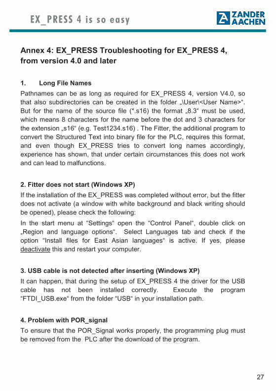
Annex 4: EX_PRESS Troubleshooting for EX_PRESS 4,
from version 4.0 and later
1. Long File Names
Pathnames can be as long as required for EX_PRESS 4, version V4.0, so
that also subdirectories can be created in the folder „\User\<User Name>“.
But for the name of the source file (*.s16) the format „8.3“ must be used,
which means 8 characters for the name before the dot and 3 characters for
the extension „s16“ (e.g. Test1234.s16) . The Fitter, the additional program to
convert the Structured Text into binary file for the PLC, requires this format,
and even though EX_PRESS tries to convert long names accordingly,
experience has shown, that under certain circumstances this does not work
and can lead to malfunctions.
2. Fitter does not start (Windows XP)
If the installation of the EX_PRESS was completed without error, but the fitter
does not activate (a window with white background and black writing should
be opened), please check the following:
In the start menu at “Settings“ open the “Control Panel“, double click on
„Region and language options“. Select Languages tab and check if the
option “Install files for East Asian languages“ is active. If yes, please
deactivate this and restart your computer.
3. USB cable is not detected after inserting (Windows XP)
It can happen, that during the setup of EX_PRESS 4 the driver for the USB
cable has not been installed correctly. Execute the program
“FTDI_USB.exe“ from the folder “USB“ in your installation path.
4. Problem with POR_signal
To ensure that the POR_Signal works properly, the programming plug must
be removed from the PLC after the download of the program.

28
EX_PRESS 4 is so easy
Zander GmbH & Co. KG
Am Gut Wolf 15
52070 Aachen, Germany
www.zander-aachen.de