government polytechnic mumbai department of ... · pdf filegovernment polytechnic mumbai...
TRANSCRIPT

Government Polytechnic Mumbai Department of Instrumentation Engineering
Programme Code: IS
Course Code: IS 11 206 Course Title: Transducer Technology
Compulsory / Optional: Compulsory
Teaching Scheme and Credits Examination Scheme
TH TU PR Total TH TS PR OR TW Total
4 -- 2 6 80 20 -- 50 -- 150
Note:
1) PR/OR marks with (*) indicates an assessment by Internal and External examiners, while
PR/OR marks without (*) indicates an assessment by Internal examiner only.
2) TW marks by Progressive Assessment.
3) Theory paper duration is 03 Hrs. and term test duration is 01 Hr.
4) Theory Paper assessment by Internal and External examiners.
Rationale:
It is necessary for the students of Instrumentation to study the principles of the transducers. They are
also often required to select a transducer for a application based on the specification.
Objectives: - Students will able to
1 Understand the principles and construction of transducers.
2. Select the transducers for specific applications.
3. Explain the operation of transducer.
4. Classify the materials, transducers.
5. Draw the diagram and input –output characteristics of different Transducers.
6. Explain the working of different transducers.
7. Explain the application of transducer.
8. Classify the transducers.
Section I
Ch.
No.
Contents: Hours Marks
1.0
Introduction to Transducers
1.1 Basic concept of measurement
1.2 Basic concept of instrument
1.3 Definition of Instrumentation
1.4 Block diagram of Generalized Measurement System (Function of each
element)
1.5 Classification of transducers:-
a) Primary and secondary transducers.
b) Active and passive transducers.
c) Analog & digital transducers.
d) transducer and Inverse transducer
e) Based on principle of Transduction.
06 08

Government Polytechnic Mumbai Department of Instrumentation Engineering
1.6 Electrical transducers and its advantages.
1.7 Selection criteria for transducer
2.0
Transducer Characteristics and Calibration
2.1 Performance Characteristics
a) Static Characteristics – Accuracy, Precision, Sensitivity, Linearity,
Resolution, Threshold, Repeatability, Reproducibility, Error(Gross Error
& Systematic Error)
b)Dynamic Characteristics- Speed of response, Lag, Fidelity.
2.2 Calibration & Standards.
i) Process of Calibration
ii) Classification of standards
iii) Standards for Calibration
08 10
3.0
Displacement transducers
3.1 Displacement – Definition, types & Units
3.2 Resistive Displacement Transducers
i) Potentiometer – Principle, types, Construction, Working, Simple
Numericals
ii) Strain gauge – Principle, Derivation of Gauge factor, Types.
a. Unbonded
b. Bonded – Wire gauge, Foil Gauge, Semiconductor strain gauge,
Rossette
iii) Selection of materials for strain Gauge
iv) Effect of temperature on strain gauge measurement
v) Simple Numerical on strain gauge factor.
3.3 Inductive Displacement transducers- Inductance principle, classification of
inductive transducers.
a) L. V. D. T. b ) R. V. D. T.
c) Eddy current gauge d) Magnetostriction gauge
3.4 Capacitive Transducers
Capacitance principle, Concept & variable capacitance due to change in
dielectric Media, area of the plate, distance between the plates.
(Diagram, construction, working principle, advantages, Disadvantages,
and applications.)
14 16
4.0
Photo transducers
4.1 Photo diode
4.2 Phototransistor
4.3 LDR
4.4 Photomultiplier tube
4.5 Photovoltaic cell
(principle, construction, working & diagram)
04 06

Government Polytechnic Mumbai Department of Instrumentation Engineering
Section II
Ch.
No.
Contents: Hours Marks
5.0
Measurement of Speed & Vibration
5.1 Measurement of speed:-
Revolution counter, Resonance tachometer, Magnetic drag tachometer
Tachometer generator
( 1 ) AC Tachometer
( 2 ) DC Tachometer
5.2 Measurement of vibrations :-
Piezoelectric accelerometers.
Diagram, construction, operation, selection criteria, advantages,
applications of above transducers.
08 10
6.0
Measurement of Force & Torque
6.1 Measurement of force :-
Hydraulic force meter, Pneumatic force meter, proving ring.
6.2 Measurement of Torque:-
In line rotating torque sensor, In line stationery torque sensor.
Diagram, construction, operation, selection criteria ,advantages
and application of above transducers.
08 10
7.0
Measurement of Viscosity and Density
7.1 Viscosity- Definition, Types -(Capillary type, Saybolt, Falling & Rolling ball
Type, Rotameter type Viscometer)
7.2 Density Measurement- Units, Specific gravity, Relative density.
7.3 Types of Densitometer
a) Hygrometer b) Bouyancy type c) Radiation type
d) Ultrasonic Sludge type e) Thermal Conductivity type
Principle, construction, working, advantages,disadvantages ,application.
10 12
8.0 Advanced sensors:
8.1 Smoke & gas detector, leak detectors, flame detectors,
8.2 Laser sensors, (Principle of operation, Features, characteristics, Range &
application )
8.3 Bar code identification system , position Encoder sensors.
06 08

Government Polytechnic Mumbai Department of Instrumentation Engineering
List of Practicals (Any Eight) :
1. Measure the linear displacement using L.V.D.T. and plot its characteristic.
2. Measurement of displacement using potentiometer- resistive transducer.
3. Measurement of angular displacement using capacitive transducer
4. Plot the characteristics of phototransistor device.
5. Plot the characteristics of photodiode device.
6. Plot the characteristics of LDR device.
7. Angular speed measurement using digital tachometer.
8. To perform the operation of smoke detector.
9. To measure the strain/load using strain gauges.
10. To measure the viscosity of fluid using capillary viscometer.
Reference Books:
Sr.
No.
Name of Book Name of Author Edition Publication
1. Instrumentation Measurement
and Analysis
Nakra, Chaudhari Second Edition Tata McGraw Hill
2. Transducers and
Instrumentation
D.V.S. Murthy Eastern Economy
Edition(EEE)
Prentice Hall India
3. Instrumentation Devices and
Systems
Rangan , Mani ,
Sharma
Second Edition Tata McGraw Hill
4. Industrial Instrumentation and
control
S.K.Singh Second Edition Tata McGraw Hill
5. A Course in Electrical and
Electronics Measurement and
Instrumentation
A. K. Sawhney Seventh Edition Dhanpat Rai & Co
6. Principles of Industrial
Instrumentation
D. Patranabis Second Edition Tata McGraw Hill
7. Instrumentation for Process
Measurement & Control
Norman A.
Anderson
Third Edition -------
8 Instrument Engineers Handbook
Vol . Proecss Measurement
Bela G.
Liptak.,Kriszta
Venczel
Revised Edition -----
Reference Books:
1) Measurement and Control Basics, 3rd Edition –by Thomas A. Hughes
2) Electrical & Electronic Measurement & instrumentation - A.K. Sawlmey.
3) Instrumentation - Rangan, Mani Sharma.
4) Principles of Industrial Instrumentation – D. Patranabis
5) Industrial Instrumentation & Control - S. K. Singh.

Government Polytechnic Mumbai Department of Instrumentation Engineering
Programme Code: IS /IF/CO
Course Code: EC 11 208 Course Title: Digital Techniques
Compulsory / Optional: Compulsory
Teaching Scheme and Credits Examination Scheme
TH TU PR Total TH TS PR OR TW Total
4 -- 2 6 80 20 50 -- -- 150
Note:
1) PR/OR marks with (*) indicates an assessment by Internal and External examiners, while
PR/OR marks without (*) indicates an assessment by Internal examiner only.
2) TW marks by Progressive Assessment.
3) Theory paper duration is 03 Hrs. and term test duration is 01 Hr.
4) Theory Paper assessment by Internal and External examiners.
Rationale:
This course forms the foundation of digital electronics. This course is introduced with the view
that students will be familiar with various digital devices and circuits which are used in Microprocessor,
Computer & other digital systems
Objectives:
The students will be able to
• Understand the concept & principles of logic devices
• Draw the logic circuit diagram
• Explain the operation of different logic devices
• Test the different logic devices
• Identify the logic devices
• Construct the circuits using logic devices
• Develop simple application using logic devices
(NOTE: Pin diagram of IC’s should not be asked in Theory Examination)
Section I
Ch.
No.
Contents: Hours Marks
01 Number Systems and Codes:
1.1 Binary numbers, decimal-binary conversion
1.2 Octal numbers, octal-binary conversion
1.3 Hexadecimal numbers, hexadecimal-binary conversion
1.4 Conversion of one number system to another system (Fractional point
number )
1.5 Codes- Natural BCD, Excess-3, Gray, Hex, Octal
1.6 Conversion of binary number to gray code and gray code to binary code.
06
08
02 Binary Arithmetic
2.1 Rules of Binary addition, subtraction, multiplication and division
2.2 Arithmetic operation for HEX, Octal, BCD code numbers
06
08

Government Polytechnic Mumbai Department of Instrumentation Engineering
2.3 Signed magnitude representation of binary numbers
2.4 1’s and 2’s complement representation of binary number
2.5 1’s complement subtraction
2.6 2’s complement subtraction
2.7 Parity, Definition of even & odd parity, its Significance, applications.
03 Logic Gates and Families:
3.1 Digital signals, representation of digital signals using positive and negative
logic
3.2 Truth table, equation and symbol of AND, OR, NAND, NOR, EX-OR, EX-NOR
gate
3.3 Symbols, Logic equation, truth table, IC numbers, Block diagram of logic
IC’s (Students must be made aware of pin diagram of logic gates.)( note to
paper setter –pin diagram should not be asked)
3.4 NOR as Universal gate, NAND as universal gate
3.5 Classification of logic families :-Saturated & non-Saturated types,
examples of each
3.6 Concept of integration: SSI,MSI,LSI,VLSI
3.7 Definition of Fan in and Fan out ,Noise Immunity,
Propagation delay (Typical values for TTL and CMOS)
I/P High,I/P Low ,O/P High ,O/P Low
08
10
04 Boolean Algebra:
4.1 Construction of Logic circuits using gates for Boolean expression, writing
Boolean expression from logic circuits.
4.2 Boolean Laws (Numerical for simplification of expression )
4.3 Demorgan’s Theorem
4.4 SOP & POS representation for logic expression
4.5 conversion of SOP to POS & POS to SOP
4.6 Representation of logical expression using minterm and maxterm
4.7 Karnaugh map (K-Map) representation of logic function
4.8 Simplification of logic function using K map for 2, 3, 4, variables (in SOP
and POS)
4.9 Realization of reduced expression using logic gates.
07
06
05 Combinational Circuits:
Truth table, Boolean expression, simplification, circuit diagram and
operation of following circuits
5.1 Half adder, full adder
5.2 Half subtractor ,full subtractor
5.3 Block diagram and truth table of Encoders
5.4 Priority Encoders ICs and Decoders
5.5 Decimal to BCD Encoders –IC 74147
BCD to 7-segment Decoder
5.6 Comparator : 1 bit & 2 bit -IC 7485
05
08

Government Polytechnic Mumbai Department of Instrumentation Engineering
Section II
Ch.
No.
Contents: Hours Marks
06 Multiplexer/ Demultiplexer:
6.1 Multiplexer
- Necessity of multiplexing
- Principle of multiplexing &
- their types –2 : 1, 4 : 1 , 8 : 1
- Block diagram, operating principle, Applications
- Multiplexer tree 32 to 1 and multiplexing 16 to 1 line
6.2 Demultiplexer
- Necessity of demultiplexing
- Principle of demultiplexing &
- their types - 1 : 2 , 1 : 4 , 1 : 8
- block diagram, operating principle, Applications
04 06
07 Flip Flops:
7.1Difference between combinational and sequential circuits
7.2 Basic concept of Flip Flop
7.3 Types of Flip Flop: RS, Clocked RS, T & D flip flop, JK
FF, Master slave JK FF ( Diagram, Symbol, Truth
table, operation, Application )
7.4 Concept of Preset & Clear, Race around condition
7.5 Types of triggering : Edge, level triggering
7.6 Flip flop IC’s
Assignment (NOT FOR THEORY EXAM): Collect information about each
flip flop IC’s directly available in the market. Write its specification and
use.
10
10
08 Counters:
8.1 Basic concept of counters
8.2 Classification of counters:
Synchronous &Asynchronous/ripple
8.3 Concept of UP & DOWN counter
8.4 3 bit /4 Bit Binary counter
8.5 BCD counter
8.6 Design MOD – N counter
Assignment (NOT FOR THEORY EXAM): Collect information about each
counter IC’s directly available in the market. Write its specification and
use.
08
10
09 Shift Registers:
9.1Definition and classification of shift registers
9.2Working of 4 Bit SISO, SIPO, PISO, PIPO Registers
9.3Circuit diagram, operation, waveform of:
9.3.1 Bi-directional shift registers
9.3.2 Universal shift registers
9.3.3 Ring Counter using D- Flip Flop
06
08

Government Polytechnic Mumbai Department of Instrumentation Engineering
9.3.4 Twisted ring counter using D/ JK Flip flop
Assignment (NOT FOR THEORY EXAM): Collect information about each
shift register IC’s directly available in the market. Write its specification
and use.
10 A-D and D-A CONVERTER
10.1 Need of data converters ,types of data converter
10.2 DAC Specification
10.3 Circuit diagram and working of R-2R Ladder DAC
10.4 ADC specification
10.5 Block diagram and working of Ramp ADC
04
06
List of Practical (Any Ten):
1. To know about digital IC’S
2. To verify Truth Table of AND, OR, NOT, NAND, NOR, Ex-OR, Ex-NOR gates using ICS.
3. To implement basic logic gates using universal logic gates(NAND ,NOR)
4. To construct and verify logic circuit for a given Boolean expression
5. To Verify De’ Morgan’s Theorem
6. To implement given logic expression after simplification using K-map
7. To construct Half Adder, Full adder & verify the Truth Table
8. To construct Half Sub-tractor, Full subtractor & verify Truth table
9. To built & study Comparator ( IC 7485 )
10. To verify Truth Tables of RS flip flop
11. To verify Truth Tables of JK flip flop
12. To verify Truth Tables of T & D flip flops
13. To construct 3 bit ripple counter using Flip Flop and verify its operation.
14. To construct and test MOD-6 asynchronous counter using IC 7490
15. To construct UP & DOWN counter & observation of its operation
16. To construct 4 bit shift register using Flip flop & its respective ICs
17. To study the working of multiplexer IC 74150/74151/747153. Implement 16:1 MUX using 8:1
MUX
18. To study the working of De-multiplexer IC 74154. Implement 1:16 DE- MUX using 1:8 DE- MUX
19. To study d/a converter using IC 0808
Reference Books:
1. Modern Digital Electronics by R. P. Jain, Publisher: Tata McGraw Hill, Education
2. Principles of Digital Electronics by Malvino A. P. and Leach, Publisher: Tata McGraw Hill,
Education
3. Digital Logic Design & Application by N. G. Palan, Publisher: Tech Max
4. Pulse Digital and Switching Waveforms by Milman and Taub, Publisher: S. Chand
5. Digital Electronics by William Gothmann, Publisher: Tata McGraw Hill, Education
6. Signetics Logic TTL Data Manual.
Government Polytechnic Mumbai Department of Instrumentation Engineering
Programme Code: IS/EC/EE/IF
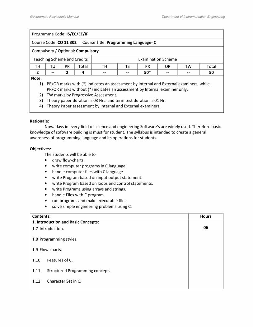
Course Code: CO 11 302 Course Title: Programming Language- C
Compulsory / Optional: Compulsory
Teaching Scheme and Credits Examination Scheme
TH TU PR Total TH TS PR OR TW Total
2 -- 2 4 -- -- 50* -- -- 50
Note:
1) PR/OR marks with (*) indicates an assessment by Internal and External examiners, while
PR/OR marks without (*) indicates an assessment by Internal examiner only.
2) TW marks by Progressive Assessment.
3) Theory paper duration is 03 Hrs. and term test duration is 01 Hr.
4) Theory Paper assessment by Internal and External examiners.
Rationale:
Nowadays in every field of science and engineering Software’s are widely used. Therefore basic
knowledge of software building is must for student. The syllabus is intended to create a general
awareness of programming language and its operations for students.
Objectives:
The students will be able to
• draw flow-charts.
• write computer programs in C language.
• handle computer files with C language.
• write Program based on input output statement.
• write Program based on loops and control statements.
• write Programs using arrays and strings.
• handle Files with C program.
• run programs and make executable files.
• solve simple engineering problems using C.
Contents: Hours
1. Introduction and Basic Concepts:
1.7 Introduction.
1.8 Programming styles.
1.9 Flow charts.
1.10 Features of C.
1.11 Structured Programming concept.
1.12 Character Set in C.
06

Government Polytechnic Mumbai Department of Instrumentation Engineering
1.13 Keywords.
1.14 Program structure.
1.15 Input and output. (Printf & Scanf)
1.16 Variable & data types.
1.17 Initialization of variables.
1.18 Primary & Secondary data types.
1.19 Arithmetic, Relational & Logical Operators and expressions.
1.20 Hierarchy of operators.
1.21 Constants.
1.22 Data type conversion in C.
2. Control Statements and Control Loop Statements:
2.1 Decision making & branching.
2.2 goto statement.
2.3 if statement.
2.4 Nesting of if - else statement.
2.5 switch statement.
2.6 Ternary Operator.
2.7 while loop.
2.8 do while loop.
2.9 for loop.
2.10 Use of break and continue statements.
08
3. Arrays, Strings, Functions, Pointers and Structures:
3.7 Array declaration.
3.8 One dimension, two dimension and multidimensional arrays.
3.9 String input /output.
10

Government Polytechnic Mumbai Department of Instrumentation Engineering
3.10 String manipulation.
3.11 Array of strings.
3.12 Basic concept of function.
3.13 Concept of library functions.
3.14 User-defined functions.
3.15 Local & global variables.
3.16 Parameter passing.
3.17 Storage classes.
3.18 Structure declaration, initialization.
3.19 Array of structure.
3.20 Basic concept of pointer.
3.21 Pointer arithmetic.
3.22 Pointers and Functions.
3.23 Pointers and Arrays.
4. File Management:
4.1 Basic concept.
4.2 Types of files: Text and Binary files.
4.3 Operations on file.
4.4 File functions.
04
5. Introduction to OOPS:
5.1 Its need and requirements.
5.2 Procedure oriented programming V/s object –oriented programming.
5.3 Programming concepts.
5.4 Features of OOPS.
5.5 Structure of C++ programming.
5.6 C++ I/O statements, manipulators.
04

Government Polytechnic Mumbai Department of Instrumentation Engineering
List of Practical:
1. Program based on input output statement.
2. Program based on arithmetic expression. (4 programs)
3. Programs based on if, if-else, nested-if (3 programs)
4. Program based on switch statement.
5. Program based on loops. (for, do... while, while). (3 programs)
6. Program based on function. (2 programs)
7. Program based on strings. (2 programs)
8. Program based on arrays and pointers. (2 programs)
9. Program based on structures.
10. Program based on File Management.
11. Write simple OOPS program.
Reference Books:
1. Programming in C by Balguruswamy, Publisher: Tata Mcgraw Hills, New Delhi.
2. Let us C by Yashwant Kanetkar, Publisher: BPB Publication, New Delhi.

Government Polytechnic Mumbai Department of Instrumentation Engineering
Programme Code: IS
Course Code: IS 11 212 Course Title: Electronic Circuits
Compulsory / Optional: Compulsory
Teaching Scheme and Credits Examination Scheme
TH TU PR Total TH TS PR OR TW Total
4 -- 2 6 80 20 50 -- -- 150
Note:
1) PR/OR marks with (*) indicates an assessment by Internal and External examiners, while
PR/OR marks without (*) indicates an assessment by Internal examiner only.
2) TW marks by Progressive Assessment.
3) Theory paper duration is 03 Hrs. and term test duration is 01 Hr.
4) Theory Paper assessment by Internal and External examiners.
Rationale:
In an Instrumentation system, a process variable has to be measured, has to be converted into
the electrical signal. Once it has been converted into the electrical signal, it is suitably processed by
using suitable electronic circuits. The course of electronic circuits is designed with an intention that after
learning this course, student will gain sufficient knowledge about discrete amplifier circuits and a few
non-sinusoidal signal-processing circuits.
Objectives: - Students will able to
1. Understand different amplifier circuits
2. Understand, use & analysis of transistor amplifier circuits.
3. Understand working of single and multistage amplifier circuits.
4. Know principle of negative feedback, types of negative feedback
5. Know about frequency responses of various amplifiers.
6. Understand working of various power amplifiers.
7. Understand working of different types of R-C and L-C Oscillators.
8. Understand working of non-sinusoidal waveform shaping and generating circuits.

Government Polytechnic Mumbai Department of Instrumentation Engineering
Section I
Ch. No. Contents Hours Marks
1. Single Stage Small Signal BJT Amplifier
1.1 Concept of :VDVS, VDCS, CDCS,CDVS
1.2 Concept of AC & DC Load lines.
1.3 Expressions for current gain, input impedance, voltage gain and output
admittance ( or output impedance ) using h-parameter model for CE
amplifiers
06
08
2. Single Stage Small Signal JFET Amplifiers
2.1 Construction & Biasing of JFET
2.2 JFET small signal models.
2.3 Analysis of common source, common drain & common gate amplifiers
2.4 Applications of JFET.
06
08
3. Multistage Small Signal BJT & FET Amplifiers
3.1 Miller’s theorem and its dual.
3.2 Direct coupled amplifiers.
3.3 Darlington pair.
3.4 R – C coupled amplifiers: Frequency response
3.5 Transformer Coupled Amplifier :Frequency response
3.6 Concept of Cascades.
3.7 Bootstrapping principle for single stage BJT amplifiers & Darlington
Pair amplifier.
10
12
4. Negative Feedback Amplifiers
4.1 Principle of negative feedback.
4.2 Advantages of negative feedback.
4.3 Types of negative feedback.
4.4 Analysis of One type of Negative Feedback : current gain voltage gain,
input impedance, output impedance.
4.5 Circuit & Working of Single stage current series Negative Feedback :
BJT and JFET amplifiers
4.6 Circuit & Working of Single stage voltage series negative feedback
amplifiers.
10
12

Government Polytechnic Mumbai Department of Instrumentation Engineering
Section II
Ch.
No.
Contents Hours Marks
5 Frequency Response of Amplifiers
5.1 Nature of frequency and phase response of an unturned amplifier.
5.2 Bode plot of the frequency and phase response.
5.3 Miller capacitance.
5.4 Frequency response of tuned amplifier
5.5 Definitions of – bandwidth, gain bandwidth product, unity gain
bandwidth.
5.6 Effect of cascading of unturned amplifiers on the bandwidth.
08
10
6 Power amplifies
6.1 Classes of power amplifies.
6.2 Performance characteristics of power amplifiers – non-linear
distortion, efficiency of conversion.
6.3 Push-pull amplifiers
6.4 Push-pull amplifiers using complementary symmetry pair.
08
10
7 Oscillators
7.1 Barkhausen criterion.
7.2 Transistor phase shift oscillator.
7.3 Wien bridge oscillator.
7.4 Resonance circuit oscillator.
7.5 Hartley oscillator.
7.6 Collpits oscillator.
7.7 Crystal oscillator.
7.9 Frequency stability and its criterion.
(Circuit Diagram ,operation ,Frequency Equation of all Oscillators )
10
12
8 Non-sinusoidal Waveform Generating and Wave shaping
8.1 Clipping and clamping circuits.
8.2 Collector coupled multivibrator-bistable, monostable and astable.
8.3 Schmitt trigger circuit. UJT relaxation oscillator.
06
08

Government Polytechnic Mumbai Department of Instrumentation Engineering
List of Practicals (Any Eight) :
1. To perform dc analysis of single stage CE amplifier and to verify it by carrying dc voltage
measurements at various points.
2. Measurement of amplifier parameters, viz voltage and current gain, input and output resistance for
the given single stage amplifiers..
3. To perform dc analysis of direct-coupled amplifier and to verify it by carrying dc voltage
Measurements at various amplifier points.
4. Measurement of various amplifier parameters for given multistage amplifiers.
5. Measurement of various amplifier parameters for given single stage series and/ or Voltage- shunt
Feedback amplifiers.
6. To plot frequency response of transformer coupled and /or tuned amplifiers.
7. To plot frequency response of transformer coupled and /of tuned amplifiers.
8. To plot frequency response of a feedback amplifier.
9. To observe the waveform and phaseshift in transistor phase shift oscillator.
10. To calculate the frequency of Weinbridge /Colpitts/Hartley oscillators.
11. To observe and plot waveform of clipping / clamping circuit.
12. To trace and observe output waveforms of multivibrator circuit (astable/bistable/monostable).
13. To prove the Miller theorem practically.
References:
Sr.N
o
Name of the Book Author Publisher Year of
Publisher
1 Electronic devices and
Circuit Theory
R. Boylestad & L.
Nasnlsky
Prentice hall of
India
1992
2 Electronic devices and
Circuit Theory
J. Milman &
C. C. Halkias
McGraw hill Inc 1967
3 Integrated Electronics : Analog
and Digital Circuits and Systems
J. Millman &
C.C. Halkias
McGraw hill Inc. 1972
4 Microelectronics J.Millman & H. Taub McGrawhill Inc. 1965
5 Electronic devices and circuits :
Discrete and integrated
Bapat Y. N Tata McGraw Hill
1978
6 Functional Electronics K. V. Ramanan McGraw Hill 1982
7 Electronic devices & Circuits : An
Introduction
Allen Mottershed Prentice Hall of
India
1973

Government Polytechnic Mumbai Department of Instrumentation Engineering
Programme Code: IS /EC/EE
Course Code: SC11 122 Course Title: Applied Mathematics
Compulsory / Optional: Compulsory
Teaching Scheme and Credits Examination Scheme
TH TU PR Total TH TS PR OR TW Total
3 1 -- 4 80 20 -- -- -- 100
Note:
1) PR/OR marks with (*) indicates an assessment by Internal and External examiners, while
PR/OR marks without (*) indicates an assessment by Internal examiner only.
2) TW marks by Progressive Assessment.
3) Theory paper duration is 03 Hrs. and term test duration is 01 Hr.
4) Theory Paper assessment by Internal and External examiners.
Rationale:
The subject intends to teach students basic facts, concepts, principle & procedure of
mathematics as a tool to analyze Engineering problems & as such lays down foundation for
understanding the engineering & core technology.
Objectives: - Students will able to
• Understand basic facts of mathematics about the field analysis of any Engineering Problem.
• Know the standard ways in which the problem can be approached.
• Apply basic concepts to engineering problem.

Government Polytechnic Mumbai Department of Instrumentation Engineering
Section I
Ch.
No.
Contents Hours Marks
1. Integration
1.1 Definition ,Standard formulae for integration (without proof)
1.2 Rules of integration, simple integration, Actual division
1.3 Method of substitution
1.4 Integration by parts
1.5 Integration by partial fraction.
1.6 Definite integral: Definition and properties of definite integral, simple
examples and examples based on the properties.
10
20
2. Applications of Definite integrals
2.1Area under the curve and area enclosed between two curves.
2.2 Mean value and R.M.S. values.
04
08
3. DIFFERENTIAL EQUATIONS
3.1 Definition ,order and degree of differential equation, formation of
differential equation
3.2Types of differential equations
* variable separable and reducible to variable separable.
* Homogeneous differential equation.
* Linear differential equation and Bernoulli’s equation.
* Partial derivatives first order only.
* Exact differential equation.
10
12

Government Polytechnic Mumbai Department of Instrumentation Engineering
Section II
Ch. No. Contents Hours Marks
4 PROBABILITY
4.1 Basic definitions, trial, event, exhaustive, favorable events.
4.2 Mutually exclusive and independent events, addition and
multiplication theorem.
4.3 Binomial distribution.
4.4 Poisson distribution
4.5 Normal distribution
10
16
5 LAPLACE TRANSFOM
5.1 Definition of Laplace transform, Laplace transform of standard
functions
5. 2 properties of Laplace transform: Linearity, first shifting property ,
second shifting property multiplication by t, division by t.
5.3 Inverse Laplace transform, properties- Linearity, first shifting,
second shifting property method of partial fractions.
5.4 Convolution theorem, l Laplace transform of derivatives.
5.5 Solutions of differential equation using Laplace transform
(up to second order equation)
10 16
6 FOURIER SERIES:
6.1 Definition of Fourier series( Euler”s formula)
6.2 Series expansion of continuous functions in the intervals (0,2l) (-l,l)
(0,2π) ,( -π,π ).
6.3 Series expansion of even and odd function.
6.4 Half range series.
04 08
References:
Sr.No. Author Title Publication
1 S.P. Deshpande Mathematics for polytechnic students Pune Vidyarthi Graha
Prakashan
2 H. K. Das Mathematics for polytechnic students
(Volume I )
S.Chand Prakashan
3 G. V. Kumbhojkar Companian to basic maths Phadke Prakashan
4 N. Raghvendra Bhatt
Late Shri R Mohan
Singh
Applied Maths Tata McGraw Hill
Publication

Government Polytechnic Mumbai Department of Instrumentation Engineering
Programme Code: EC / IS
Course Code: EE 11 311 Course Title:Electrical Machines
Compulsory / Optional: Compulsory
Teaching Scheme and Credits Examination Scheme
TH TU PR Total TH TS PR OR TW Total
3 -- 2 5 80 (3 Hrs.) 20 50 (I&E) -- -- 150
Rationale:
This subject will help the students to understand facts, concepts, principles, operation,control
and applications of electrical machines like motors, transformers etc. This study is necessary because
students work as supervisors in the industry. Knowledge of electrical machines is also important for
designing electronic control systems or process control.
Objectives:
The students will be able to
• understandpolyphase circuits.
• explain working and construction of transformer.
• find efficiency and regulation of transformer.
• state types and applications of d.c. motors.
• state the types and applications of three phase and single phase.
• control speed of motors.
• state use of different drives for different purposes.
• select industrial drive for a particular application.
Section I
Contents: Hours Marks
1. Polyphase circuit:
1.1 Difference between single phase and polyphase system.
1.2 Generation of three-phase a.c. supply.
1.3 Advantages of three-phase supply over single-phase supply.
1.4Concept of phase sequence and balanced/unbalanced load.
1.5Relation between phase and line values of current and voltage in Star and Delta
balanced system.
1.6 Power in 3 phase system with Balance load.
06
10
2.Transformer (Single phase):
2.1 Constructional features and types. (shell, core & auto).
2.2 Transformer on no load & on load.
2.3 Ideal Transformer.
2.4 Transformer losses.
2.5 Transformer Testing: oc&sc test.
08
14

Government Polytechnic Mumbai Department of Instrumentation Engineering
2.6 Direct Loading Test.
2.6 Rating, Efficiency & Voltage Regulation. [Numerical problems on test
results
2.7 Auto Transformer.
2.8 Three phase transformer – Types of connections and applications.
3. D.C.Motor:
3.1 Constructional features & working principle.
3.2 Different parts of DC motor & their functions.
3.3 Types of DC motor – connection diagram, speed/ torque
characteristics, applications.
3.4 Necessity of starter.
3.5 Study of 3 point starter.
3.6 Speed control of DC Shunt & Series motor.
i) Rheostatic control ii) Flux control iii) Armature control.
10
16
Section II
Contents: Hours Marks
4.Induction Motor:
4.1 Principle advantages & disadvantages.
4.2 3ph Squirrel cage induction motor – construction, application
4.3 Slip Ring Induction motor – construction, application
4.4 Synchronous speed, % slip [simple problems]
4.5 Starting of 3 ph induction motor
i) DOL ii) Star Delta iii) Reduced voltage
4.6 Starting Torque & Torque – Slip characteristics.
4.7 Speed control: Voltage control, Rotor resistance control &
frequency control.
09
15
5.Single phase Induction motor:
5.1 Induction motor: (Schematic representation, torque speed
characteristics & application)
i ) Capacitor start / capacitor run motor
ii) Split phase motor
iii) Shaded pole motor
5.2 Synchronous motors: (Schematic representation, torque speed
characteristics & application)
i) Reluctance motor
ii) Hysteresis motor
5.3 Series Motor – Universal motor(Schematic representation,
torque speed characteristics & application)
5.4 Two phase servo motor (Schematic representation, torque speed
characteristics & application)
06
10

Government Polytechnic Mumbai Department of Instrumentation Engineering
5.5 Stepper motor: working principle, construction, types & applications.
6.Industrial Application of Electric Motor:
6.1 Advantages of Electric Drive
6.2 Classification of electric drive
6.3 Factors governing selection of motor
6.4 Electrical characteristics, Mechanical consideration, size, rating&Cost of
D.C.
Motor & Induction Motor
6.5 Motors for different industrial drives
6.6 Electric Braking: i) Plugging applied to D.C. motor & Induction motor
ii) Rheostat braking applied to D.C. motor & Induction motor
09
15
List of Practical:
12. To verify line and phase values for star and Delta connected balanced load.
13. To determine full load efficiency and voltage regulation of single-phase transformer by direct
loading.
14. To perform O.C. and S.C. test on 1- phase transformer.
15. To study speed control of DC shunt motor byi) Armature Voltage Control ii) Field Control
16. To plot Speed Torque characteristics of DC shunt motor.
17. To reverse direction of rotation of DC shunt motor.
18. To measure slip of 3-phase induction motor andto reverse direction of rotation of 3- phase
Induction motor.
19. Observe andidentify various types of Single Phase Induction Motors.
20. To plot Speed – Torque characteristics of 3- phase induction motor.
21. To prepare selection chart for AC and DC Drives.
Reference Books:
1. Electrical Technology (Volume II) by B. L. Thereja and A. K. Thereja, Publisher: S. Chand and Co.
Ltd., New Delhi
2. Electrical Machines by S.K.Bhattacharya, Publisher: Tata - McGraw-Hill Pub. Co. Ltd., New Delhi