gold silver plus manual
TRANSCRIPT

8/10/2019 GOLD SILVER Plus Manual
http://slidepdf.com/reader/full/gold-silver-plus-manual 1/80
1
B.B.10.0112
InformationSILVER+ (Art.Nr. 10331-01)
SILVER21+ (Art.Nr. 10321-01)
SILVERdirect+ (Art.Nr. 10330-01)GOLD+ (Art.Nr. 10433-01)
5. Auflage / 5th Edition / 5. Edition 10 13

8/10/2019 GOLD SILVER Plus Manual
http://slidepdf.com/reader/full/gold-silver-plus-manual 2/80
2 Information SILVER+ / GOLD+ Decoder
Technische Daten / Technical Data / Données techniques:
Maximale
Dauerbelastbarkeit desgesamten Decoders
Maximum continuous
current-carryingcapacity of totaldecoder
Charge totale
maximaleautorisée dudécodeur
1,0 A
MotorausgangDauer/Spitze
Motor outputContinuous / maximumpower
Sortie moteurContinu/En pointe
1,0 / 1,6 A
Funktionsausgänge A, B, C, D und E
Function outputs A, B, C, D and E
Sorties de fonction A, B, C, D et E
je/resp. 500 mA
Gesamtbelastbarkeit derFunktionsausgänge
Total current-carryingcapacity of functionoutputs
Charge totale dessorties de fonction
500 mA
Lokadressen Locomotive addresses Adresses de
locomotive
1 - 9999
Fahrstufen Running notches(speed steps)
Crans de marche 14, 27, 28, 128
8/10/2019 GOLD SILVER Plus Manual
http://slidepdf.com/reader/full/gold-silver-plus-manual 3/80
3
D
E
FMotor A C D EB F
Orange
GrünGreenVert
ViolettPurpleViolet
BraunBrownBraun
GrauGreyGris
RotRedRouge
SchwarzBlack
Noir
WeißWhiteBlanc
GelbYellowJaune
BlauBlueBleu
F F
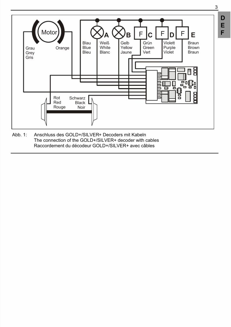
Abb. 1: Anschluss des GOLD+/SILVER+ Decoders mit KabelnThe connection of the GOLD+/SILVER+ decoder with cablesRaccordement du décodeur GOLD+/SILVER+ avec câbles

8/10/2019 GOLD SILVER Plus Manual
http://slidepdf.com/reader/full/gold-silver-plus-manual 4/80
4 Information SILVER+ / GOLD+ Decoder
Kontaktbelegung der NEM652 Schnittstelle
Pin allocations of the NEM652 interface
Attribution des contacts de l'interface NEM 652
Orange Pin 1 Pin Bedeutung Meaning Signification
1 Motoranschluß 1 Motor connection 1 Sortie moteur 1
2 Licht hinten (-) (F-Ausg.B)
rear headlight (Functionoutput B)
Feux sign. arrière (-) (sortieB)
3 Funktionsausgang C Function output C Sortie de fonction C
4 Linker Radschleifer Left rail pickup Prise de courant gauche
5 Motoranschluß 2 Motor connection 2 Sortie moteur 2
6 Licht vorn (-) (F-Ausg. A) front headlight (Functionoutput A)()
Feux sign. avant (-) (sortie A)
7 Gemeinsamer Leiter für
Licht (+)
Function positive common Fil commun de retour (+)
8 Rechter Radschleifer Right rail pickup Prise de courant droite
Abb. 2: NEM652 interfaceInterface NEM 652

8/10/2019 GOLD SILVER Plus Manual
http://slidepdf.com/reader/full/gold-silver-plus-manual 5/80
5
D
E
F
Code1211
1 22
Abb. 3: SILVER21+: 21polige SchnittstelleSILVER21+: 21-pole plugSILVER21+: 21-pole Interface
8/10/2019 GOLD SILVER Plus Manual
http://slidepdf.com/reader/full/gold-silver-plus-manual 6/80
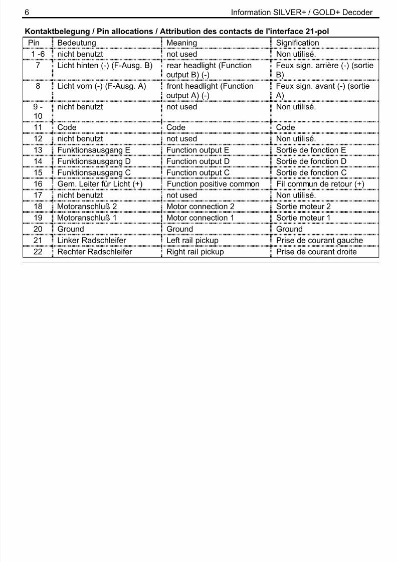
6 Information SILVER+ / GOLD+ Decoder
Kontaktbelegung / Pin allocations / Attribution des contacts de l'interface 21-pol
Pin Bedeutung Meaning Signification
1 -6 nicht benutzt not used Non utilisé.
7 Licht hinten (-) (F-Ausg. B) rear headlight (Functionoutput B) (-)
Feux sign. arrière (-) (sortieB)
8 Licht vorn (-) (F-Ausg. A) front headlight (Functionoutput A) (-)
Feux sign. avant (-) (sortie A)
9 -10
nicht benutzt not used Non utilisé.
11 Code Code Code
12 nicht benutzt not used Non utilisé.13 Funktionsausgang E Function output E Sortie de fonction E
14 Funktionsausgang D Function output D Sortie de fonction D
15 Funktionsausgang C Function output C Sortie de fonction C
16 Gem. Leiter für Licht (+) Function positive common Fil commun de retour (+)
17 nicht benutzt not used Non utilisé.
18 Motoranschluß 2 Motor connection 2 Sortie moteur 219 Motoranschluß 1 Motor connection 1 Sortie moteur 1
20 Ground Ground Ground
21 Linker Radschleifer Left rail pickup Prise de courant gauche
22 Rechter Radschleifer Right rail pickup Prise de courant droite

8/10/2019 GOLD SILVER Plus Manual
http://slidepdf.com/reader/full/gold-silver-plus-manual 7/80
7
D
E
F
1
Funktionsausgang DFunction output DSortie de fonction D
Funktionsausgang EFunction output ESortie de fonction E
Gemeinsamer Leiter für Licht (+)
Function positive commonFil commun de retour (+)
Abb. 4: SILVERdirect+: NEM652 interface
Interface NEM 652

8/10/2019 GOLD SILVER Plus Manual
http://slidepdf.com/reader/full/gold-silver-plus-manual 8/80
8 Information SILVER+ / GOLD+ Decoder
U+ (rot/red/rouge)Clk (blau/blue/bleu)Dat (grau/grey/gris)Gnd (schwarz/black/noir)
Abb. 5: S.U.S.I. – Schnittstelle / S.U.S.I. interface / Interface S.U.S.I. (GOLD+)
U+chargeGND
Abb. 6: USP – Anschluss / USP connection / Raccordement USP (GOLD+)

8/10/2019 GOLD SILVER Plus Manual
http://slidepdf.com/reader/full/gold-silver-plus-manual 9/80
9
D
E
F
Nicht geeignet für Kinder unter 3 Jahren wegen verschluckbarer Kleinteile. Bei unsachgemäßemGebrauch besteht Verletzungsgefahr durch funktionsbedingte Kanten und Spitzen! Nur für trockeneRäume. Irrtum sowie Änderung aufgrund des technischen Fortschrittes, der Produktpflege oderanderer Herstellungsmethoden bleiben vorbehalten. Jede Haftung für Schäden und Folgeschäden
durch nicht bestimmungsgemäßen Gebrauch, Nichtbeachtung dieser Gebrauchsanweisung, Betriebmit nicht für Modellbahnen zugelassenen, umgebauten oder schadhaften Transformatoren bzw.sonstigen elektrischen Geräten, eigenmächtigen Eingriff, Gewalteinwirkung, Überhitzung, Feuchtig-keitseinwirkung u.ä. ist ausgeschlossen; außerdem erlischt der Gewährleistungsanspruch.
Not suitable for children under three because of the danger of swallowing the small constituentpieces. Improper use can result in injury from functionally necessary points and edges. For use in
dry areas only. We reserve the right to make changes in line with technical progress, productmaintenance or changes in production methods. We accept no responsibility for direct or indirectdamages resulting from improper use, non-observance of instructions, use of transformers or otherelectrical equipment which is not authorised for use with model railways, or transformers or otherelectrical equipment which has been altered or adapted or which is faulty. Furthermore, we acceptno responsibility for damages resulting from unsupervised modifications to equipment or acts ofviolence or overheating or effects of moisture etc. In all such cases, guarantees shall become void.

8/10/2019 GOLD SILVER Plus Manual
http://slidepdf.com/reader/full/gold-silver-plus-manual 10/80
10 Information SILVER+ / GOLD+ Decoder
Les appareils numériques sont non indiqués pour les enfants en dessous de 3 ans en raison despetites pièces susceptibles d'être avalées. En cas d'utilisation incorrecte existe un danger deblessures dues à des arêtes vives ! Les appareils sont uniquement utilisables dans des locauxsecs. Sauf erreur due à des modifications en raison de progrès techniques, de la mise à jour des
produits ou d'autres méthodes de production. Est exclue toute responsabilité pour des dommageset conséquences de dommages suite à un emploi des produits non conforme à la destination, à unnon-respect du mode d'emploi, à une exploitation autre que dans un chemin de fer miniature, avecdes transformateurs de courant modifiés ou détériorés ou d'autres appareils électriques, à uneintervention autoritaire, à une action violente, à une surchauffe, à l'humidité, entre autres choses.De surcroît est éteinte toute prétention à l'exécution de la garantie.

8/10/2019 GOLD SILVER Plus Manual
http://slidepdf.com/reader/full/gold-silver-plus-manual 11/80
11
D1 Wichtige Sicherheitshinweise:
Digital plus Lokdecoder dürfen ausschließlich mit dem Digital plus by Lenz System oder eineranderen handelsüblichen Digitalsteuerungen mit NMRA-Konformitäts-Siegel verwendet werden.Fragen Sie im Zweifelsfall beim Lieferanten des Systems nach.Die in den technischen Daten angegebenen Belastbarkeiten dürfen nicht überschritten werden. Siemüssen sicherstellen, dass diese maximale Belastbarkeit nicht überschritten wird. Bei einerÜberlastung wird der Decoder zerstört! Die Bauteile des Decoders dürfen auf keinen FallMetallteile des Chassis oder des Lokgehäuses berühren. Es entsteht ein Kurzschluß innerhalb desDecoders, und er wird zerstört.Wickeln Sie aber den Decoder nie in Isolierband ein, hierdurch wird die notwendige Luftzirkulationum den Decoder verhindert. Kleben Sie vielmehr die Metallteile der Lokomotive mit Isolierband o.ä.ab. Hierdurch können Sie ungewollte Kurzschlüsse vermeiden, ohne dass der Decoder 'erstickt'.Fixieren Sie den Decoder mit doppelseitigem Klebeband.Mit Digital plus Decodern ausgerüstete Lokomotiven dürfen auf Zweileiteranlagen nicht an derOberleitung betrieben werden, da die Lokomotive durch Aufgleisen in der falschen Richtung diedoppelte Fahrspannung erhalten kann. Hierbei wird der Decoder zerstört!
Bevor Sie einen Digital plus Decoder einbauen, prüfen Sie die Lokomotive vor dem Umbau im
normalen Gleichstrombetrieb auf einwandfreie Funktion. Ersetzen Sie verschlissene Kohlen unddurchgebrannte Birnchen. Nur eine Lok mit einwandfreier Mechanik kann mit einem Decodereinwandfrei fahren.
8/10/2019 GOLD SILVER Plus Manual
http://slidepdf.com/reader/full/gold-silver-plus-manual 12/80
12 Information SILVER+ / GOLD+ Decoder
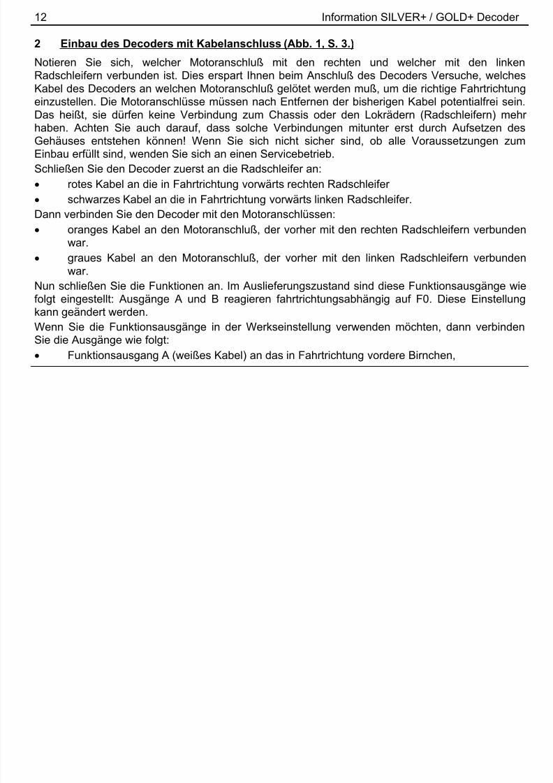
2 Einbau des Decoders mit Kabelanschluss (Abb. 1, S. 3.)
Notieren Sie sich, welcher Motoranschluß mit den rechten und welcher mit den linkenRadschleifern verbunden ist. Dies erspart Ihnen beim Anschluß des Decoders Versuche, welchesKabel des Decoders an welchen Motoranschluß gelötet werden muß, um die richtige Fahrtrichtung
einzustellen. Die Motoranschlüsse müssen nach Entfernen der bisherigen Kabel potentialfrei sein.Das heißt, sie dürfen keine Verbindung zum Chassis oder den Lokrädern (Radschleifern) mehrhaben. Achten Sie auch darauf, dass solche Verbindungen mitunter erst durch Aufsetzen desGehäuses entstehen können! Wenn Sie sich nicht sicher sind, ob alle Voraussetzungen zumEinbau erfüllt sind, wenden Sie sich an einen Servicebetrieb.Schließen Sie den Decoder zuerst an die Radschleifer an:
rotes Kabel an die in Fahrtrichtung vorwärts rechten Radschleifer
schwarzes Kabel an die in Fahrtrichtung vorwärts linken Radschleifer.Dann verbinden Sie den Decoder mit den Motoranschlüssen:
oranges Kabel an den Motoranschluß, der vorher mit den rechten Radschleifern verbundenwar.
graues Kabel an den Motoranschluß, der vorher mit den linken Radschleifern verbundenwar.
Nun schließen Sie die Funktionen an. Im Auslieferungszustand sind diese Funktionsausgänge wiefolgt eingestellt: Ausgänge A und B reagieren fahrtrichtungsabhängig auf F0. Diese Einstellungkann geändert werden.Wenn Sie die Funktionsausgänge in der Werkseinstellung verwenden möchten, dann verbindenSie die Ausgänge wie folgt:
Funktionsausgang A (weißes Kabel) an das in Fahrtrichtung vordere Birnchen,

8/10/2019 GOLD SILVER Plus Manual
http://slidepdf.com/reader/full/gold-silver-plus-manual 13/80
13
D Funktionsausgang B (gelbes Kabel) an das in Fahrtrichtung hintere Birnchen.Sind die Glühbirnchen nicht elektrisch mit dem Chassis der Lokomotive verbunden (wir nennendiese dann "potentialfrei"), so schließen Sie den anderen Pol der Lampen an das blaue Kabel an,wie in der Abbildung unten zu sehen ist. Besteht eine Verbindung zwischen Glühbirnen und
Chassis, so bleibt das blaue Kabel unbenutzt. Bei Anschluß am blauen Kabel leuchten dieGlühbirnen etwas heller, außerdem funktioniert dann die richtungsabhängige Beleuchtung auch imBetrieb mit normalem Gleichstrom. Welche der Varianten Sie umsetzen, hängt von der Konstruktionder Lokomotive ab.Für den Anschluß von Leuchtdioden gilt: Blaues Kabel ist "Pluspol" (Anodenseite der LED),Funktionsausgang ist "Minuspol" (Kathodenseite der LED). Die Spannung am Funktionsausgangbeträgt ca. 16V. Vergessen Sie nicht den erforderlichen Vorwiderstand.
Schließen Sie nun noch den Funktionsausgang C und D an, sofern eine weitere Funktion in IhrerLok vorhanden ist.
Funktionsausgang C (grünes Kabel) an eine weitere Funktion,
Funktionsausgang D (violettes Kabel) an eine weitere Funktion,
Funktionsausgang E (braunes Kabel) an eine weitere Funktion.
3 Einbau des SILVER+, SILVER21+, GOLD+-Decoders mit Schnittstellenstecker NEM652
(Abb. 2, S. 4)Der Schnittstellenstecker gemäß NEM 652 und NMRA ermöglicht einen schnellen undproblemlosen Umbau von Lokomotiven.Ziehen Sie den Brückenstecker von der Schnittstelle der Lokomotive ab. Bewahren Sie diesenStecker sorgfältig auf. Stecken Sie nun den Stecker des Decoders so auf die Schnittstelle auf, dass
8/10/2019 GOLD SILVER Plus Manual
http://slidepdf.com/reader/full/gold-silver-plus-manual 14/80

8/10/2019 GOLD SILVER Plus Manual
http://slidepdf.com/reader/full/gold-silver-plus-manual 15/80
15
Dkönnen. Ist dies nicht der Fall, so ist Ihnen bei der Verkabelung möglicherweise ein Fehlerunterlaufen. Kontrollieren und ändern Sie ggf. die Verkabelung.Nun können Sie mit der Lokomotive auf Ihrer Anlage zur ersten Probefahrt starten.
6 Eigenschaften der Decoder
Im Folgenden geben wir Ihnen einen kurzen Überblick über die Eigenschaften der Decoder undderen Einstellung.
Ausführliche Informationen zu den Eigenschaften und deren Einstellungen finden Sie im
"Handbuch Plus-Decoder" welches Sie von der Website der Lenz Elektronik GmbH
herunterladen können: www.lenz-elektronik.de/pdf/download.php
6.1 Leistung und Schutzeinrichtungen
Der Motorausgang ist bis 1A dauernd belastbar, und dies ohne spezielle Montage auf Kühlflächen!Die kurzzeitige Spitzenbelastbarkeit beträgt 1,8A. Die Funktionsausgänge können mit je 500mAbelastet werdenDer Decoder ist gegen Überlast, Kurzschluß und Übertemperatur geschützt. Im Fehlerfall wird inCV30 ein entsprechendes Bit gesetzt welches Auskunft über die Art des Fehlers gibt. Dieses Bitkann per Programmierung gelöscht werden.
6.2 MotorsteuerungDer Decoder verfügt über eine Regelung mit hochfrequenter Ansteuerung (23kHz). Zur Anpassungan das jeweilige Lokmodell können einfach 6 verschiedene Motortypen in CV50 ausgewähltwerden. Zusätzlich ist es möglich, bei Auswahl der Motortypen 4 und 5 ein Feintuning über dieCV113 und CV114 vorzunehmen. Selbstverständlich kann sowohl die hochfrequente Ansteuerung
16 I f ti SILVER / GOLD D d

8/10/2019 GOLD SILVER Plus Manual
http://slidepdf.com/reader/full/gold-silver-plus-manual 16/80
16 Information SILVER+ / GOLD+ Decoder
als auch die Regelung abgeschaltet werden. Weiterhin steht die CV9 zur Anpassung derWiederholrate zur Verfügung.Die minimale (CV2), maximale (CV5) und mittlere (CV6) Geschwindigkeit kann eingestellt werden,der Decoder passt die Geschwindigkeitskennlinie dabei dynamisch an, um einen sanften Verlauf
ohne Knickstellen zu gewährleisten. Unabhängig davon ist es außerdem möglich, eine individuelleGeschwindigkeitskennlinie zu programmieren.Der Decoder besitzt weiterhin einen so genannten EMK-Teiler, der eine Anpassung des Decodersan verschiedene Motortypen ermöglicht. Je nach verwendetem Motor kann es vorkommen, dasseine digital gesteuerte Lokomotive im Vergleich zum konventionellen Betrieb keine ausreichendeHöchstgeschwindigkeit erreicht. In diesem Fall aktivieren Sie den EMK Teiler, indem Sie Bit 6 (5) inder CV 50 setzen. Die Lok erreicht dann eine höhere Endgeschwindigkeit, gleichzeitig steigt die
minimal mögliche Geschwindigkeit geringfügig.6.3 Fahrstufen
Der Decoder kann mit dem 14/27 oder 28/128 Fahrstufenmodus betrieben werden. Die Einstellungdazu nehmen Sie in der CV29 vor.
6.4 Abschaltbare Verzögerung
Mit der Funktion 4 (Werkseinstellung, kann in CV59 geändert werden) können die Anfahr- und
Bremsverzögerung sowie der konstante Bremsweg während des Betriebes abgeschaltet werden.Die Verzögerungen sind abgeschaltet, so lange die Funktion aktiv ist.
17
8/10/2019 GOLD SILVER Plus Manual
http://slidepdf.com/reader/full/gold-silver-plus-manual 17/80
17
D6.5 Konstanter Bremsweg
6.5.1 Konstanter Bremsweg mit ABCFunktionsweise: Erkennt der Decoder im ABC Betrieb den Befehl "Halt", so kommt nach demeingestellten Bremsweg zum Halten. Dieser Bremsweg ist unabhängig von der gefahren
Geschwindigkeit.Sie aktivieren den konstanten Bremsweg bei ABC durch Setzen des Bit 1(0) in der CV51.
6.5.2 Konstanter Bremsweg mit Fahrstufe 0Funktionsweise: Beim Übergang von einer beliebigen Fahrstufe zur Fahrstufe 0 (z.B. durch Drehendes Knopfs am Handregler an den linken Anschlag) legt die Lok / der Zug einen einstellbaren,festgelegten Bremsweg zurück. Dieser Bremsweg ist unabhängig von der gefahren
Geschwindigkeit. Der konstante Bremsweg ist nur wirksam, wenn die Fahrstufe auf den Wert 0geändert wird. Wird die Fahrstufe von z.B. 28 auf 10 herabgesetzt, so wirkt diegeschwindigkeitsabhängige Verzögerung aus CV3.Sie aktivieren Sie den konstanten Bremsweg bei Fahrstufe 0 durch Setzen des Bit 8(7) in der CV51 Ausführliche Informationen zur Einstellung des Bremsweges finden Sie im „Handbuch
Plus-Decoder“, welches Sie von der Website der Lenz Elektronik GmbH herunterladen können:www.lenz-elektronik.de/pdf/download.php
Weitere wichtige Hinweise:
Die Länge des zurückgelegten Bremsweges wird in der CV52 eingestellt. Je nach Wert indieser CV ergibt sich ein unterschiedlicher Bremsweg.
Wollen Sie sowohl mit Fahrstufe 0 als auch mit ABC den konstanten Bremsweg nutzen,setzen Sie sowohl das Bit beide Bits in CV51.
18 Information SILVER+ / GOLD+ Decoder

8/10/2019 GOLD SILVER Plus Manual
http://slidepdf.com/reader/full/gold-silver-plus-manual 18/80
18 Information SILVER+ / GOLD+ Decoder
Während der Rangiergang eingeschaltet ist (Standardeinstellung F3), ist der konstanteBremsweg abgeschaltet, es wirkt die Verzögerung aus CV3.
Der konstante Bremsweg ist ebenfalls abgeschaltet, wenn die Verzögerungen im Decoderper Funktion (Standardeinstellung F4) ausgeschaltet sind.
Die beiden letztgenannten Eigenschaften können Sie z.B. auch dann sinnvoll einsetzen, wenn Sieeinen bereits begonnenen Bremsvorgang vorzeitig abbrechen wollen.
Beim Bremsen mit Gleichspannung ist der konstante Bremsweg nicht wirksam.
6.6 Rangiergang
Der Rangiergang halbiert die Geschwindigkeit. Eine besonders feinfühlige Regelung zumRangieren wird so möglich. Mit der Funktion 3 (Werkseinstellung, kann in CV58 geändert werden)schalten Sie den Rangiergang ein und aus. Wenn der Rangiergang eingeschaltet ist, ist derkonstante Bremsweg ausgeschaltet. Der Rangiergang ist eingeschaltet, so lange die Funktion aktivist.
6.7 ABC = einfacher Signalhalt und Langsamfahrt
Bei Verwendung der ABC-Bremsmodule ist ein besonders einfacher Signalhalt realisierbar. DieseModule erzeugen abhängig von der Signalstellung im Bremsabschnitt vor dem Signal eine Asymmetrie der Gleisspannung. Hierauf reagiert der Decoder. In Verbindung mit dem konstanten
Bremsweg ist exaktes Anhalten vor roten Signalen kein Problem. Selbstverständlich ist dieDurchfahrt in Gegenrichtung möglich. Weiterhin ist die Umsetzung des Signalbildes "Langsamfahrt"kein Problem, wobei die hierbei höchstens zu fahrende Geschwindigkeit CV53 eingestellt werdenkann.
19
8/10/2019 GOLD SILVER Plus Manual
http://slidepdf.com/reader/full/gold-silver-plus-manual 19/80
19
DWährend des Signalhaltes oder Langsamfahrt können sämtliche Funktionen betätigt werden, auchrückwärts vom roten Signal wegfahren ist möglich! Mit besonderen ABC-Modulen kann sehr einfacheine Blockstrecke aufgebaut werden. Aktiviert wird ABC durch Bit 2 (1) in CV51.Ist der Rangiergang eingeschaltet oder sind die Verzögerungen ausgeschaltet, so ist die ABC-
Technik nicht aktiv!
6.8 Pendelzugsteuerung
Bei Einsatz der ABC-Bremsmodule ist eine Pendelzugsteuerung einstellbar. Zwei verschiedeneOptionen gibt es hierbei: Pendeln mit und ohne Zwischenhalt. Im zweiten Modus werden auchLangsamfahrabschnitte berücksichtigt.Die Pendelzugsteuerung wird in CV51 Bit 4 (3) und Bit 5 (4) aktiviert. Die Aufenthaltsdauer amStreckenende wird in CV54 zwischen 1 und 255 Sekunden eingestellt.
6.9 Zuordnung der Funktionsausgänge zu den Funktionen des Digitalsystems (Mapping)
Hiermit legen Sie fest, welche Funktion des Digitalsystems die Funktionsausgänge ein- undausschaltet. Die Ausgänge können den Funktionen F0 und F1 (richtungsabhängig) oder denFunktionen F2 bis F28 frei zugeordnet werden.Die Zuordnung nehmen Sie in den CVs 33 bis 47 sowie 129 bis 144 vor.
6.10 Lichteffekte an den Funktionsausgängen
In der CV60 stellen Sie die Lichteffekte für die Funktionsausgänge A und B ein, in der CV62 dieEffekte an den Ausgängen C und D. Wollen Sie die Effekte mit einer Funktion des Digitalsystemsschalten, so können Sie die Zuordnung zu den Funktionen F1 bis F8 in der CV61 (für F-Ausgänge A und B) und CV64 (für F-Ausgänge C und D) vornehmen. Welche Effekte Sie einstellen könnensehen Sie in der Tabelle der unterstützen CVs weiter unten.
20 Information SILVER+ / GOLD+ Decoder
8/10/2019 GOLD SILVER Plus Manual
http://slidepdf.com/reader/full/gold-silver-plus-manual 20/80
20 Information SILVER+ / GOLD+ Decoder
6.11 Die S.U.S.I. Schnittstelle (nur GOLD+ Decoder)
In Kooperation der Firmen DIETZ und LENZ enstand das Konzept einer Sound- undFunktionsschnittstelle für Lokdecoder. Sinn dieser Schnittstelle ist es, Sound- und andereFunktionsmodule auf besonders einfache Weise an einen Lokdecoder anzuschließen.
Das S.U.S.I. Modul erhält über die Schnittstelle Informationen über die Fahrstufe, den Zustand derFunktionen etc. und reagiert entsprechend, z.B. wird der Ton der Glocke abgespielt oder es ändertsich der Auspuffschlag.Die Qualität dieser Sound-Effekte ist ausschließlich vom verwendeten S.U.S.I. Modul abhängig undnicht vom Lokdecoder selbst!
6.11.1 Anschluss eines S.U.S.I. – Moduls
An die S.U.S.I. Schnittstelle können alle Sound- und/oder Funktionsmodule angeschlossen werden,die der Spezifikation der S.U.S.I. Schnittstelle entsprechen. Zum Anschluss eines Sound- oderFunktionsmoduls befindet sich ein 4-poliger Steckverbinder auf dem Decoder, sehen Sie dazu Abb 3, Seite 6. Die Belegung der Lötflächen ist gemäß der Spezifikation der SUSI-Schnittstellegewählt. Die Angabe der Kabelfarben enspricht der Empfehlung dieser Spezifikation.Stecken Sie den Stecker Ihres S.U.S.I. Modules vorsichtig in den Steckverbinder auf dem Decoder.Der Stecker lässt sich nur ein einer Richtung einsetzen.
6.11.2 Einstellungen (Programmierung) des S.U.S.I. ModulsWie bei den Decodern, so besteht auch bei S.U.S.I. Modulen die Möglichkeit diverse Einstellungenvorzunehmen. Diese Einstellungen werden ebenfalls in Configurations Variablen (CVs)gespeichert. Wenn Sie Veränderungen an diesen CVs vornehmen wollen, so gehen Sie genau sovor, als würden Sie die CVs des Lokdecoders ändern. Das S.U.S.I. Modul wird gewissermaßen
21

8/10/2019 GOLD SILVER Plus Manual
http://slidepdf.com/reader/full/gold-silver-plus-manual 21/80
21
D"durch den Decoder hindurch" programmiert. Der Lokdecoder erkennt anhand der Nummer der CV,ob das S.U.S.I. Modul gemeint ist und leitet die Programmierbefehle über die S.U.S.I. Schnittstelleweiter. Welche Einstellungen an Ihrem S.U.S.I. Modul vorgenommen werden können erfahren Sieaus der Betriebsanleitung zu Ihrem Modul.
Die Einstellungen am S.U.S.I. Modul können sowohl über "Programmieren während des Betriebes(PoM)" als auch über das "Programmieren auf dem Programmiergleis" vorgenommen werden. BeiEinsatz von Digital plus by Lenz
® Systemen können Sie mit PoM die CVs 1 bis 999 verändern,beim "Programmieren auf dem Programmiergleis" erreichen Sie zurzeit die CVs 1 bis 256. Für dieS.U.S.I. Module wurde der CV-Bereich 897 bis 1024 festgelegt. Um diese CV-Nummern zuerreichen, ist im GOLD+ Decoder eine besondere Programmiermethode eingebaut.Bei dieser Programmiermethode wird CV126 als Zeiger und CV127 zum Transport des Wertesverwendet.Der Funktionsablauf ist wie folgt: In die Zeiger-CV126 wird das Ziel (Nummer der CV)eingeschrieben, danach in die Transport-CV127 der Wert, der in das Ziel transportiert werden soll.Soll die Ziel-CV nur gelesen werden, so wird nach dem Einschreiben des Ziels in CV126 dieTransport CV127 ausgelesen.Da in eine CV nur Werte bis 255 eingegeben werden können, die CVs für SUSI aber bei 897beginnen, ist die Zeiger CV mit dem Offset 800 "vorgeladen". Sie müssen nur noch die Differenzzur gewünschten Ziel-CV eingeben, beispielsweise für die Ziel-CV897 also die Zahl 97.
Beispiel 1: Sie wollen in die CV 897 des S.U.S.I. Moduls den Wert 01 einschreiben. Gehen Sie sovor:1. Schreiben Sie 897-800=97 in die Zeiger-CV126
22 Information SILVER+ / GOLD+ Decoder
8/10/2019 GOLD SILVER Plus Manual
http://slidepdf.com/reader/full/gold-silver-plus-manual 22/80
22 Information SILVER+ / GOLD+ Decoder
2. Schreiben Sie den gewünschten Wert "01" in die Transport-CV 127. Der Decoder übergibtnun den Programmierbefehl "Schreibe den Wert "01" in die CV "897" über die S.U.S.I.Schnittstelle an das angeschlossene Modul.
Beispiel 2: Sie wollen den aktuellen Wert der CV 902 des S.U.S.I. Moduls auslesen:
1. Schreiben Sie 902-800=102 in die Zeiger-CV1262. Lesen Sie die Transport-CV127. Es wird der in der CV 902 des angeschlossenen Moduls
enthaltene Wert angezeigt.
6.12 USP - Uninterruptable Signal Processing (nur GOLD + Decoder)
Die intelligente USP-Schaltung sorgt in Verbindung mit dem optionalen Energiespeicher dafür,dass die Lok auch verschmutzte Gleisabschnitte oder stromlose Herzstücke überwinden kann. Der
Energiespeicher ist nicht im Lieferumfang des Decoders enthalten und wird separat in dasFahrzeug eingebaut.Für den Anschluss der Energiespeichers (z.B. Power 1) sind auf dem Decoder Lötflächenvorgesehen. Sehen Sie dazu Abb. 4, Seite 8. Löten Sie die betreffenden Kabel des Energiespeichers an den Lötflächen an. Achten Sie darauf, dass Sie keine Kurzschlüsse zuanderen Lötflächen oder den Lötflächen untereinander herstellen.
6.13 Kupplungssteuerung
Der Decoder ermöglicht an allen Funktionsausgängen eine komfortable Steuerung vonfernbedienbaren Kupplungen. Der gewählte Ausgang stellt für eine einstellbare Zeit die volleLeistung (Kickdauer), nach Ablauf dieser Zeit eine reduzierte Leistung zur Verfügung. Wie weit dieLeistung reduziert wird, ist ebenfalls einstellbar. Außerdem können Sie einstellen, ob die Lokwährend des Kupplungsvorgangs fährt und wie lange.
23
8/10/2019 GOLD SILVER Plus Manual
http://slidepdf.com/reader/full/gold-silver-plus-manual 23/80
23
D6.14 RailCom
Der Decoder ist mit der RailCom Funktion ausgerüstet. Es können neben der Lokadresse auchweitere Daten (z.B. aktuelle Geschwindigkeit, CV-Inhalt) über das Gleis von der Lok zurückgesendet werden. Die gesendeten Informationen werden von einem RailCom Detektor empfangen
und z.B. an einer Anzeige sichtbar gemacht. Werkseitig ist das Senden von RailCom Dateneingeschaltet (CV29 Bit 4[3]).
24 Information SILVER+ / GOLD+ Decoder

8/10/2019 GOLD SILVER Plus Manual
http://slidepdf.com/reader/full/gold-silver-plus-manual 24/80
7 Einstellung des Decoders
Lokadresse, Anfahr- und Bremsverzögerung sowie alle anderen Eigenschaften des Decoderskönnen durch PROGRAMMIERUNG beliebig oft geändert werden. Diese Eigenschaften werden imDecoder dauerhaft, also auch beim Abschalten der Betriebsspannung, "aufgehoben". In der(amerikanischen) Normung werden die Speicher als "Configuration Variable", kurz: "CV"bezeichnet. Das Einschreiben/Auslesen der Werte erfolgt elektronisch, die Lokomotive muß alsonach Einbau des Decoders nicht mehr geöffnet werden. Zur Programmierung des Decoders könnenfolgende Digital plus Geräte eingesetzt werden: Zentrale LZ100 / LZV100 (mit einem Handregleroder dem Interface); SET02; Compact.Sie können den Inhalt der CVs sowohl durch "Programmieren während des Betriebes" (Außer CV1,CV17 und CV18) oder durch "Programmieren auf dem Programmiergleis" verändern.
Wie die Programmierung im Einzelnen durchgeführt wird, erfahren Sie aus den Betriebsanleitungender genannten Geräte.Der Decoder ist im Lieferzustand auf Betrieb mit Adresse 3, 28 Fahrstufen, geschwindigkeitsab-hängigem Bremsweg, Funktionsausgänge A und B richtungsabhängig und nicht gedimmteingestellt. Der Decoder kann sofort mit diesen Einstellungen verwendet werden.
7.1 Rücksetzen des Decoders auf Werkseinstellung:
Wenn Sie alle CVs des Decoders auf Werkseinstellung zurücksetzen möchten, so schreiben Sie indie CV8 den Wert 8 oder 33. . Ausgenommen sind die CVs der Geschwindigkeitskennlinie (CV67-CV94). Beachten Sie aber, dass in der CV29 das Bit 5 gelöscht wird, der Decoder also aufVerwendung der Werkskennlinie eingestellt wird. Die CVs eines angeschlossenen S.U.S.I. Moduls
werden hierbei nicht zurückgesetzt!
25
8/10/2019 GOLD SILVER Plus Manual
http://slidepdf.com/reader/full/gold-silver-plus-manual 25/80
D8 Liste der unterstützten CV
CVWerte-
bereich /Bit
BedeutungWerks-
einstellung
1 1-127 Basis – LokadresseDies ist die Nummer, mit der Sie die Loks im Digital plus by Lenz® System aufrufen. Für die Verwendung mit Digital plus by Lenz® Geräten ist nur der Bereich 1-99 zugelassen. Beim Schreibendieser CV wird im Decoder automatisch CV19(Mehrfachtraktionsadresse) und in CV29 das Bit 6 (Verwendungder erweiterten Adresse) gelöscht.
3
2 0-255 Mindestanfahrspannung Vmin 13 0-255 Anfahrverzögerung 64 0-255 Bremsverzögerung 55 0-255 Maximalgeschwindigkeit Vmax 2546 0-255 mittlere Geschwindigkeit Vmid 487 - Versionsnummer
SILVER+ (Art.Nr. 10331-01) 95
SILVER21+ (Art.Nr. 10321-01) 99SILVERdirect+ (Art.Nr. 10330-01) 98GOLD+ (Art.Nr. 10433-01) 91
8 - Herstellerkennung 99
26 Information SILVER+ / GOLD+ Decoder

8/10/2019 GOLD SILVER Plus Manual
http://slidepdf.com/reader/full/gold-silver-plus-manual 26/80
9 0-63 Wiederholrate 1517 192 –231 erweiterte Lokadresse, höherwertiges Byte 19218 0-255 erweiterte Lokadresse, niederwertiges Byte 10019 0-127 Mehrfachtraktionsadresse
Für die Verwendung mit Digital plus by Lenz®
Geräten ist nur derBereich 1-99 zugelassen.
0
28 Bit RailCom Konfiguration 3 (dec)1 (0) 1 Kanal 1 freigegeben für Adress-Broadcast 12 (1) 1 Kanal 2 freigegeben für Daten und Acknowledge 1
29 Bit Einstellungen 1 14 (dec)1 (0) Richtung der Lok
0 normal: Lok fährt nach vorne, wenn der Pfeil auf demHandregler nach oben zeigt.
1 vertauscht: Lok fährt nach vorne, wenn der Pfeil auf demHandregler nach unten zeigt.
0
2 (1) Fahrstufenmodus:0 Betrieb mit 14 oder 27 Fahrstufen. Diese Einstellung wählen
Sie bei Verwendung des Decoders mit Digitalsystemen, die
den 28/128-Fahrstufenmodus nicht unterstützen.1 Betrieb mit 28 oder 128 Fahrstufen. Diese Einstellung wählenSie bei Verwendung des Decoders mit Digitalsystemen, dieden 28/128-Fahrstufenmodus unterstützen.
1
3 (2) Betriebsart:0 Lok fährt nur im Digitalbetrieb
1
27

8/10/2019 GOLD SILVER Plus Manual
http://slidepdf.com/reader/full/gold-silver-plus-manual 27/80
D1 Lok fährt im konventionellen als auch im digitalen Betrieb,fliegender Wechsel ist möglich.
4 (3) 0 RailCom Senden ausgeschaltet1 RailCom Senden eingeschaltet
0
5 (4) 0 Decoder verwendet Werkskennlinie1 Decoder verwendet selbstprogrammierte Kennlinie6 (5) 0 Decoder verwendet Basisadresse (aus CV1)
1 Decoder verwendet erweiterte Adresse (aus CV17 u. CV18)0
7-8(6-7) nicht verwendet 030 Bit Fehleranzeige 0
1 (0) 1 Lampen- Kurzschluss 0
2 (1) 1 Übertemperatur 03 (2) 1 Motor-/Gleis- Kurzschluss 0CV
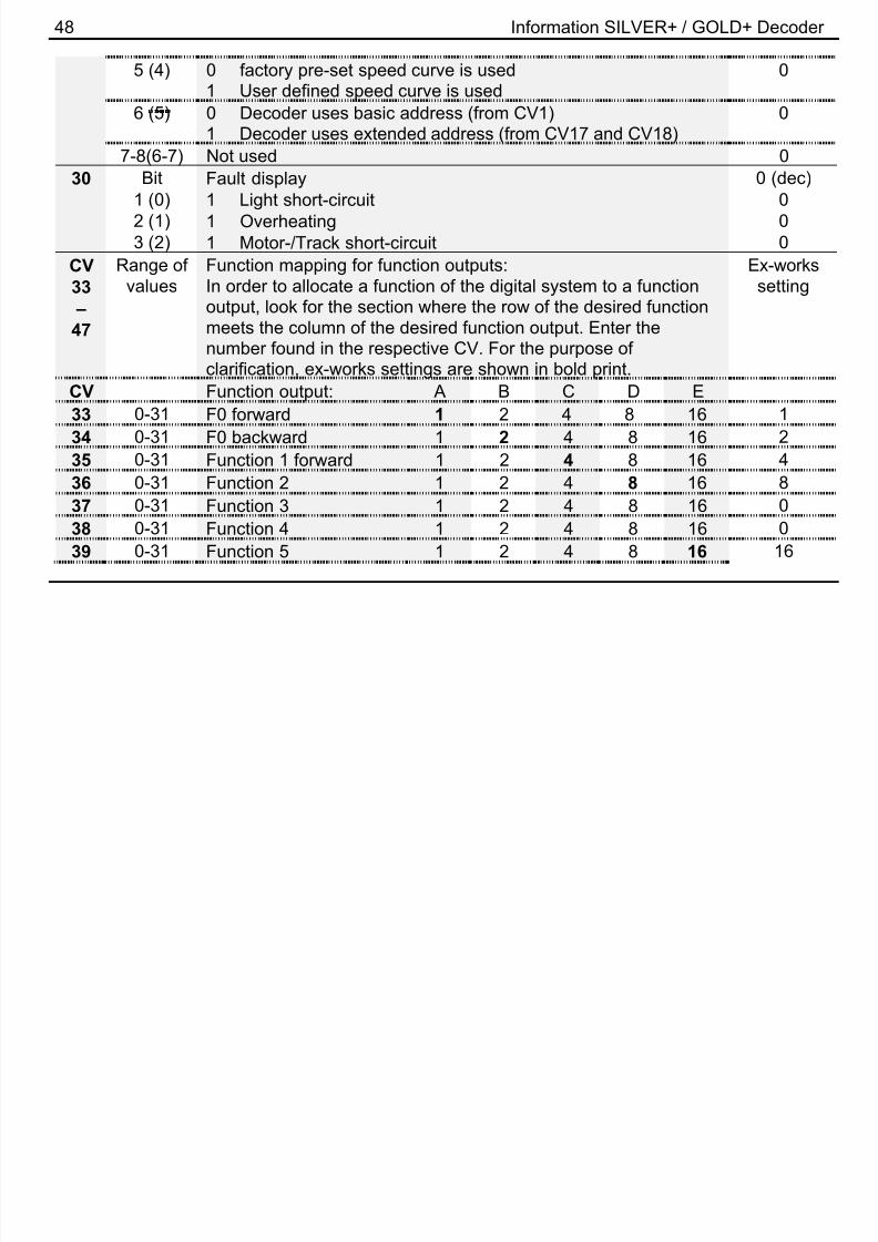
33
–
47
Werte-bereich
Funktionszuordnung (Mapping) für Funktionsausgänge:Um eine Funktion des Digitalsystems einem Funktionsausgangzuzuordnen sucht man den Schnittpunkt der Zeile der gewünsch-ten Funktion mit der Spalte des gewünschten Funktionsaus-gangs. Die gefundene Zahl wird in die entsprechende CVeingetragen. Zur Anschauung sind die werkseitig eingestelltenWerte fett gedruckt.
Werks-einstellung
CV Funktionsausgang: A B C D E33 0-31 F0 vorwärts 1 2 4 8 16 134 0-31 F0 rückwärts 1 2 4 8 16 235 0-31 Funktion 1 vorwärts 1 2 4 8 16 4
28 Information SILVER+ / GOLD+ Decoder
8/10/2019 GOLD SILVER Plus Manual
http://slidepdf.com/reader/full/gold-silver-plus-manual 28/80
36 0-31 Funktion 2 1 2 4 8 16 837 0-31 Funktion 3 1 2 4 8 16 038 0-31 Funktion 4 1 2 4 8 16 039 0-31 Funktion 5 1 2 4 8 16 16
40 0-31 Funktion 6 1 2 4 8 16 041 0-31 Funktion 7 1 2 4 8 16 042 0-31 Funktion 8 1 2 4 8 16 043 0-31 Funktion 9 1 2 4 8 16 044 0-31 Funktion 10 1 2 4 8 16 045 0-31 Funktion 11 1 2 4 8 16 046 0-31 Funktion 12 1 2 4 8 16 0
47 0-31 Funktion 1 rückwärts 1 2 4 8 16 450 Bit Motor - Konfiguration 0 (dec)
1-4 (0-3) Auswahl des Motortyps 0-5, Eingabe als Dezimalzahl6 (5) 0 EMK-Teiler nicht aktiv
1 EMK-Teiler aktiv0
7 (6) 0 Regelung eingeschaltet1 Regelung ausgeschaltet
0
8 (7) 0 Motoransteuerung hochfrequent (ca. 23 kHz)1 Motoransteuerung niederfrequent (ca. 19 Hz)
0
51 Bit Brems – Konfiguration 0 (dec)1 (0) 1 konstanter Bremsweg bei ABC-Betrieb aktiviert 02 (1) 1 ABC aktiviert 0
29

8/10/2019 GOLD SILVER Plus Manual
http://slidepdf.com/reader/full/gold-silver-plus-manual 29/80
D3 (2) 1 Richtungsabhängigkeit von ABC ist ausgeschaltet 04 (3) 1 Pendelbetrieb ohne Zwischenhalt aktivieren 05 (4) 1 Pendelbetrieb mit Zwischenhalt aktivieren 06 (5) 1 mit Gleichspannung polaritätsunabhängig anhalten (wird nur
beachtet, wenn in CV29 Bit 3 gelöscht ist)
0
7 (6) nicht benutzt8 (7) konstanter Bremsweg über Fahrstufe 0 aktiviert 0
52 0-255 Bremsweg bei aktiviertem konstanten Bremsweg 5053 0-255 Langsamfahrt bei ABC 4854 0-255 Aufenthaltsdauer bei Pendelbetrieb, 1 bis 256 Sekunden 455 0-255 stellt die Helligkeit am F-Ausgängen A ein, 255=max 255
56 0-255 stellt die Helligkeit am F-Ausgängen B ein, 255=max 25557
-
59,
61
Funktionszuordnung (Mapping):Jedes Bit der CV steht für eine Funktion des Digitalsystems:Bit 1(0) für Funktion 1, Bit 2(1) für Funktion 2 und so weiter bisBit 8(7) für Funktion 8. Wenn Sie eine Funktion dem Dimmenzuordnen wollen, so muss das betreffende Bit gesetzt werden.
57 0-255 Mapping Dimmen für Funktionasausgänge A bis D (kein Mapping
werkseitig eingestellt)
0
58 0-255 Rangiergang (werkseitige Einstellung F3) 459 0-255 Abschalten der Verzögerung (werkseitige Einstellung F4) 860 0-255 Effekte an den F-Ausgängen A und B. Einerstelle des Wertes
steht für F-Ausgang A, Zehnerstelle für F-Ausgang B:0
30 Information SILVER+ / GOLD+ Decoder

8/10/2019 GOLD SILVER Plus Manual
http://slidepdf.com/reader/full/gold-silver-plus-manual 30/80
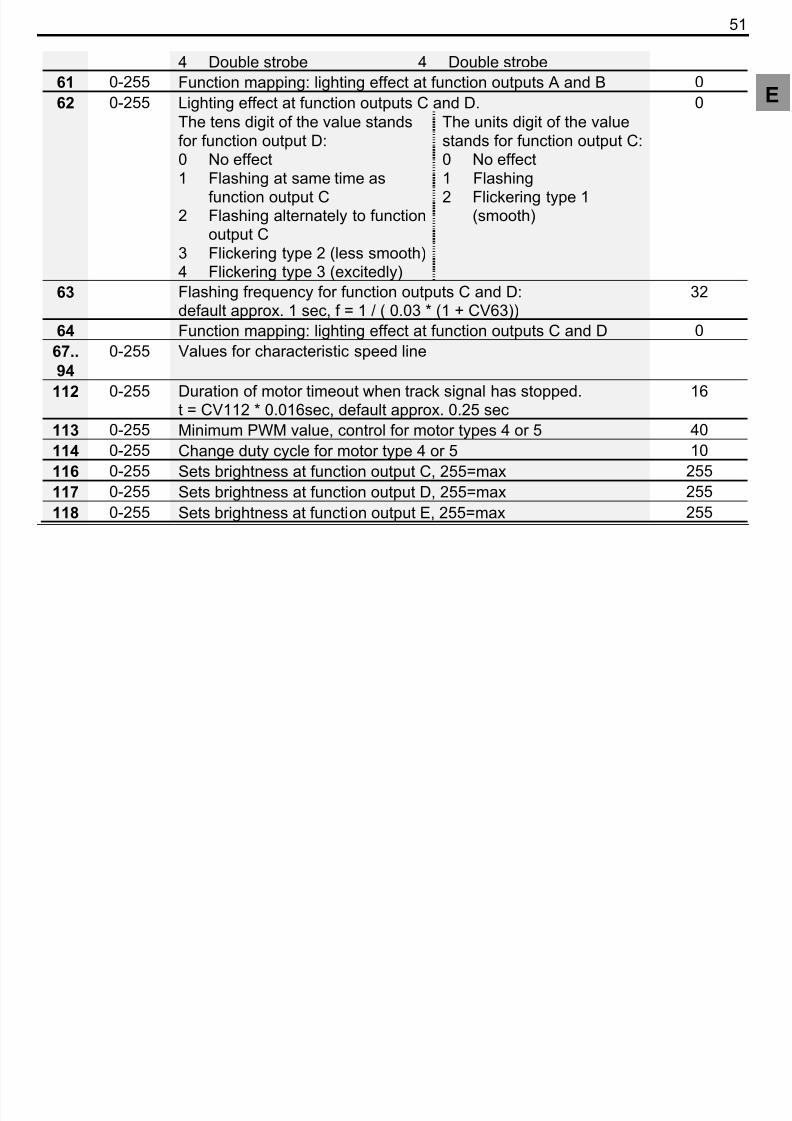
Zehnerstelle für. F-Ausgang B:0 kein Effekt1 Marslight2 Gyralight3 Strobe4 Doublestrobe
Einerstelle für. F-Ausgang A:0 kein Effekt1 Marslight2 Gyralight3 Strobe4 Doublestrobe
61 0-255 Schalten der Lichteffekte F-Ausgang A und B 062 0-255 Effekte an den F-Ausgängen C und D. 0
Zehnerstelle des Wertes für F- Ausgang D:0 kein Effekt1 Blinken im Gleichtakt zu
F-Ausgang C2 Blinken im Gegentakt zu
F-Ausgang C3 Flackern Typ 2 (unruhiger)4 Flackern Typ 3 (hektisch)
Einerstelle des Wertes für F- Ausgang C:0 kein Effekt1 Blinken2 Flackern Typ 1 (ruhig)
63 Blinkfrequenz für F-Ausgänge C und D:für eine bestimmte Frequenz (f ) ergibt sich der Wert ins CV63
aus der Formel: CV63 = (1 / f *0,03 ) - 1Defaultwert ergibt eine Frequenz von ca. 1 Hz.
32
64 Funktionszuordnung Lichteffekte F-Ausgang C und D 067 -
94
0-255 Werte für die Geschwindigkeitskennlinie.
31

8/10/2019 GOLD SILVER Plus Manual
http://slidepdf.com/reader/full/gold-silver-plus-manual 31/80
D112 0-255 Zeitdauer für Motornachlauf wenn kein Gleissignal mehrvorhanden. t = CV112 * 0,016sec, default ca. 0,25sec
16
113 0-255 Minimaler PWM-Wert bei Regelung für Motorentyp 4 oder 5 40114 0-255 Änderung Dutycycle für Motorentyp 4 oder 5 10
116 0-255 stellt die Helligkeit am F-Ausgang C ein, 255=max 255117 0-255 stellt die Helligkeit am F-Ausgang D ein, 255=max 255118 0-255 stellt die Helligkeit am F-Ausgang E ein, 255=max 255126 0-255 Zeiger CV für SUSI, Offset ist 800 102127 0-255 Transport CV für SUSI 0128 Servicenummer (aktuelle Nummer bitte auslesen) -
Funktionszuordnung F13 – F28 zu den Ausgängen -
CV Funktionsausgang: A B C D E129 0-31 Funktion 13 1 2 4 8 16 0130 0-31 Funktion 14 1 2 4 8 16 0131 0-31 Funktion 15 1 2 4 8 16 0132 0-31 Funktion 16 1 2 4 8 16 0133 0-31 Funktion 17 1 2 4 8 16 0134 0-31 Funktion 18 1 2 4 8 16 0135 0-31 Funktion 19 1 2 4 8 16 0136 0-31 Funktion 20 1 2 4 8 16 0137 0-31 Funktion 21 1 2 4 8 16 0138 0-31 Funktion 22 1 2 4 8 16 0
32 Information SILVER+ / GOLD+ Decoder

8/10/2019 GOLD SILVER Plus Manual
http://slidepdf.com/reader/full/gold-silver-plus-manual 32/80
139 0-31 Funktion 23 1 2 4 8 16 0140 0-31 Funktion 24 1 2 4 8 16 0141 0-31 Funktion 25 1 2 4 8 16 0142 0-31 Funktion 26 1 2 4 8 16 0
143 0-31 Funktion 27 1 2 4 8 16 0144 0-31 Funktion 28 1 2 4 8 16 0
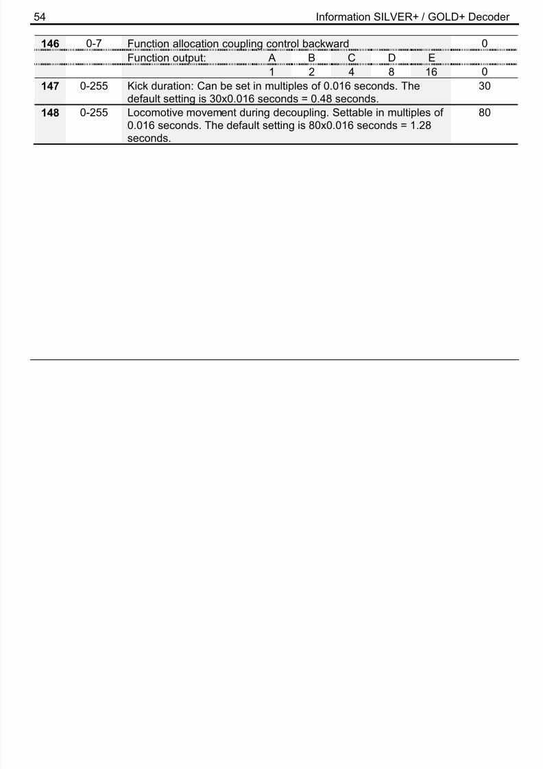
145 0-16 Funktionszuordnung Kupplungssteuerung vorwärtsFunktionsausgang: A B C D E
1 2 4 8 16 0146 0-16 Funktionszuordnung Kupplungssteuerung rückwärts
Funktionsausgang: A B C D E1 2 4 8 16 0
147 0-255 „Kickdauer“: Einstellbar in Vielfachen von 0,016 Sekunden. DieWerkseinstellung enspricht 30x0,016 Sekunden = 0,48 Sekunden
30
148 0-255 Verfahren der Lok beim Entkuppeln. Einstellbar in Vielfachen von0,016 Sekunden. Die Werkseinstellung enspricht80x0,016 Sekunden = 1,28 Sekunden
80
33

8/10/2019 GOLD SILVER Plus Manual
http://slidepdf.com/reader/full/gold-silver-plus-manual 33/80
E
1 Important safety instructions
Digital plus locomotive decoders are to be used only with Lenz Digital plus or other standard digitalcontrol systems with an NMRA-conformance seal. If in doubt, ask the system supplier.Please note that the maximum current-carrying capacity of the outputs may not be exceeded as thiscould damage the decoder! Under no circumstances may the parts of the locomotive decoder beallowed to touch the metal components of the chassis or the body of the locomotive as this couldcause a short-circuit within the locomotive decoder leading to damage.Never wrap the locomotive decoder in insulating tape as this prevents the necessary air circulationaround the decoder. Instead, use insulating tape or something similar around the metal componentsof the locomotive to avoid unintentional short-circuits without depriving the decoder of air. Usedouble-sided adhesive-tape to affix the decoder.
Locomotives equipped with Digital plus decoders must not be run using powered overhead lineseither on conventional DC control or DCC control systems as this could subject the locomotive todouble the voltage and damage the decoder.The current-carrying capacities noted in the technical data above may not be exceeded.Before installing a Digital plus decoder, check the locomotive in normal DC operation to ensure thatit works correctly before modifying the locomotive.Replace worn wheel contacts, motor brushes and blown bulbs. Only a locomotive that is
mechanically OK will function properly with a locomotive decoder.
34 Information SILVER+ / GOLD+ Decoder

8/10/2019 GOLD SILVER Plus Manual
http://slidepdf.com/reader/full/gold-silver-plus-manual 34/80
2 Installing the decoder via cable connection (Abb. 1, p. 3.)
Please note which motor connection is linked to the right rail pickups and which to the left. If you dothis you will not have to try out which decoder cable needs to be soldered to which motorconnection to achieve the desired direction of travel.
After removing the original connections to the motor brushes, the motor brushes must be potential -free and completely isolated from both tracks. This means that they may not be connected in anyway to the chassis or to the rail pickups of the locomotive. Bear in mind that a connection like this issometimes made simply when the chassis is put back!Please contact a service centre if you are in any doubt as to whether all necessary preconditionsfor the installation are fulfilled!First connect the decoder to the pickups of the locomotive:
red cable to the pickups which are on the right-hand side of the locomotive in relation to thedirection of travel
black cable to the pickups which are on the left-hand side of the locomotive in relation to thedirection of travel
Then connect the decoder to the motor connections:
orange cable to the motor connection previously connected to the right pickups
grey cable to the motor connection previously connected to the left pickups.
Now connect the functions. Ex-works default settings for the functions are configured as follows:Function outputs A and B as direction-dependent outputs reacting to F0. This configuration can bealtered as desired.If you wish to use the function outputs in their initial configuration, connect the outputs as follows:
35

8/10/2019 GOLD SILVER Plus Manual
http://slidepdf.com/reader/full/gold-silver-plus-manual 35/80
E
function output A (white cable) to the bulb which is at the front in relation to the direction oftravel
function output B (yellow cable) to the bulb which is at the back in relation to the direction oftravel
If the functions inside the locomotive (e.g. the bulbs of the direction-dependent lights) are notelectrically connected to the chassis (i.e. if they are "potential-free"), connect the other pole of thefunction to the blue cable as shown in the illustration. If a connection between functions andchassis does exist, the blue cable remains unused. When connected to the blue cable, the bulbsshine somewhat brighter and, in addition, the direction-dependent lighting then also works innormal DC operation. Which option you choose depends on the design of the locomotive.For the connection of the LEDs, note that the blue cable is the positive pole (anode side of theLED) and the function output is the negative pole (cathode side of the LED). The voltage at thefunction output is approx. 16 V. Please do not forget the necessary protective resistor.Now connect outputs C and D (if your locomotive has further functions):
function output C (green cable) to another locomotive function,
function output D (green cable) to another locomotive function,.
function output E (brown cable) to another locomotive function.
3 Installing the SILVER+, SILVER21+, GOLD+ decoder via interface plug NEM652
(Abb. 2, p. 4)
These decoders come with a NEM652 / NMRA RP-9.1.1 medium plug. This plug makes theinstallation of these decoders very simple.
36 Information SILVER+ / GOLD+ Decoder

8/10/2019 GOLD SILVER Plus Manual
http://slidepdf.com/reader/full/gold-silver-plus-manual 36/80
To install the decoder simply remove the dummy plug in your locomotive and install the decoderplug. To ensure the headlights work correctly you must align the plug properly. Pin 1 of the plugconnects to the orange wire. Ensure this is aligned to Pin 1 of the locomotive. If the plug is installedwrong way round the lights will not work.When installing the plug ensure that the pins are not bent or broken.
4 Installing the SILVER 21 decoder (Abb. 3, p. 5)
These decoders come with a 21-pole plug. This plug makes the installation of these decoders verysimple.To install the decoder simply remove the dummy plug in your locomotive and install the decoderplug. Ensure Pin 1 of the decoder is aligned to Pin 1 of the locomotive. When installing the plugensure that the pins are not bent or broken.
5 Testing the installation
Place the locomotive on the programming track (without its housing) and read the address. Thedecoder is programmed ex-works to the address 03. If you have connected the decoder correctlythus far, you should now be able to read the address. If you are not able to do so, it is possible thatyou have made a mistake when connecting the cables. Do not subject the locomotive to full running
track power until you obtain the correct "03" address read-out. Check the cable connections andchange them as required. You should now be able to send your locomotive on its first test run onyour layout.
37
8/10/2019 GOLD SILVER Plus Manual
http://slidepdf.com/reader/full/gold-silver-plus-manual 37/80
E
6 Features of the decoder
The following contains a short survey of the features of the GOLD+ decoder as well as informationon how to set them.
You can find detailed information on the features and their settings in the “Manual Plus
Decoders” that you can download from the Lenz Elektronik GmbH website www.lenz-elektronik.de
6.1 Capacity and protection equipment
The motor output has a current-carrying capacity of up to 1A even without special installation oncooling surfaces! The short-term maximum current-carrying capacity is 1.8A. The function outputshave current-carrying capacities of 500mA each.The decoder is protected against overloading, short circuits and overheating. In case of a fault, thecorresponding bit is set in CV30 which will state the type of fault which has occured. This bit can bedeleted via programming.
6.2 Motor control
The decoder is equipped with a high-frequency motor control (23kHz). Six different motor types (notto be confused with motor designs, such as a bell-type armature motor) can be selected in CV50 toadapt to the respective locomotive model. These motor types include parameter sets which have
been specially adapted to the respective models. Moreover, it is possible to carry out fine-tuning viaCV113 or CV114 when selecting motor types 4 or 5. Of course you can switch off both the high-frequency drive as well as the control system itself. You can still use CV9 to adjust the repeat rate.
38 Information SILVER+ / GOLD+ Decoder

8/10/2019 GOLD SILVER Plus Manual
http://slidepdf.com/reader/full/gold-silver-plus-manual 38/80
The minimum (CV2), maximum (CV5) and mid (CV6) speed can be set; the decoder automaticallyadapts the characteristic speed line dynamically to ensure a steady, smooth curve. Independentlyof this, it is also possible to program an individual characteristic speed line.The decoder still has a so-called EMF switch which makes it possible to adjust the decoder todifferent motor types. Depending on the motor type used, it is possible that a digitally controlledlocomotive cannot reach an adequate maximum speed compared to a locomotive in conventionaloperation. If this is the case, activate your EMF switch by setting Bit 6 in CV 50. The locomotive willthen reach a higher maximum speed while the minimum speed is also slightly increased.
6.3 Running notches (Speed steps)
The decoder can be operated in the 14/27 or the 28/128 running-notches mode. This setting ismade in CV29.
6.4 Disabling of delay
Use function 4 (ex-works setting, can be altered in CV60) to disable the starting and braking delayas well as the constant braking distance during operation. The delays are disabled as long as thefunction is active.
6.5 Constant braking distance
6.5.1 Constant braking distance with ABCFunctioning: If the decoder recognises the command “Stop“ while in ABC mode, the locomotive willstop after the set braking distance has been covered. This braking distance is independent of thespeed of the locomotive.You can activate the constant braking distance with ABC by setting bit 1(0) in CV51.
39
8/10/2019 GOLD SILVER Plus Manual
http://slidepdf.com/reader/full/gold-silver-plus-manual 39/80
E
6.5.2 Constant braking distance with speed step 0Functioning: During the transition from any speed step to speed step 0 (e.g. by turning the knob ofthe manual control to the very left) the locomotive or train covers a settable, defined brakingdistance. This distance is independent of the speed of the locomotive. The constant brakingdistance is only effective if the speed step is set to 0. If the speed step is decreased from e.g. 28 to10, the speed-dependent delay from CV3 becomes effective.Set bit 8(7) in CV51 to activate the constant braking distance with speed step 0.You can find detailed information on setting the braking distance in the “Manual Plus Decoders”that you can download from the Lenz Elektronik GmbH website www.lenz-elektronik.de/pdf/download.php
Important advice:
The length of the covered braking distance is set in CV52. The braking distance differs dependingon the value set in this CV.If you want to use the constant braking distance with both speed step 0 and ABC, set both bits inCV51.While the shunting speed is switched off (default setting F3), the constant braking distance isdisabled and the delay from CV4 becomes effective.The constant braking distance is also disabled if the delays set in the decoder are disabled by
means of the corresponding function.The two latter features can also be used sensibly if you wish to interrupt a current braking processprematurely.The constant braking distance does not work if the layout is operated in analogue DC mode.
40 Information SILVER+ / GOLD+ Decoder

8/10/2019 GOLD SILVER Plus Manual
http://slidepdf.com/reader/full/gold-silver-plus-manual 40/80
6.6 Shunting speed
The shunting speed halves the speed. This facilitates particularly sensitive control of the shuntingprocess. Use function 3 (ex-works setting, can be altered in CV59) to enable and disable theshunting speed. If the shunting speed is enabled, the constant braking distance is disabled. Theshunting speed is enabled as long as the function is active.
6.7 ABC = simple signal stop and slow approach
You can carry out a particularly simple signal stop using the ABC braking module. Depending onthe signal position, this module creates an asymmetric track voltage in the braking section in frontof the signal. The decoder reacts to this. Combined with the constant braking distance, precise on-the-spot stopping in front of red signals is not a problem. Of course, passage in the oppositedirection is also possible. The signal indication "slow approach/caution" does not pose a problem;
the respective maximum-speed can be set in CV53.You can operate all functions during the signal stop or slow approach – you can even reverse awayagain from the red signal! These special ABC modules can be used to assemble a very simpleblock section. Activate the ABC module by setting Bit 2 (1) in CV51.The ABC feature is not active whenever the shunting speed is switched on or the delay is disabled.
6.8 Push-pull train control
A push-pull train control can be set if the ABC braking module is used. There are two differentoptions: push-pull operation with and without intermediate stops. The latter also takes slow-approach sections into account.The push-pull train control is activated in CV51, Bit 4 (3) and Bit 5 (4). The stopping time at the endof the track is set in CV54 (1 to 255 sec).
41
8/10/2019 GOLD SILVER Plus Manual
http://slidepdf.com/reader/full/gold-silver-plus-manual 41/80
E
6.9 Allocating function outputs to the functions of the digital system (mapping)
Here you can define which function of the digital system is used to switch the function outputs on oroff. The outputs can be allocated to functions F0 and F1 (direction-dependent) or functions F2 toF28 as desired. This is allocated in CVs 33 to 47 and in CV129 to 144.
6.10 Lighting effect at function outputsThe lighting effect for the function outputs A and B is set in CV60 and for the function outputs C andD in CV62. If you wish to switch the effects with a function of the digital system, you can make theallocations to functions F1 to F8 in CV61 (for function outputs A and B) and CV64 (for functionoutputs C and D). The effects available are shown in the table of the supported CVs further below.
6.11 The S.U.S.I. interface (only GOLD + Decoder)
The sound and function interface concept for locomotive decoders was devised in 2002 incooperation with the company DIETZ. The purpose of the interface is to facilitate the particularlyeasy connection of sound and other function modules to locomotive decoders.The S.U.S.I. module receives information about the running notch, the status of the functions etc.via the interface and reacts accordingly, for example the sound of a bell is played or the locomotivesound changes.
The quality of these sound effects depends solely on the S.U.S.I. module and not on the locomotivedecoder!
6.11.1 Connecting a S.U.S.I. moduleYou may connect all sound and/or function modules to the S.U.S.I. interface which correspond tothe interface’s specification. A 4-pin connector on top of the decoder serves for the connection of asound or function module (See Fig. 3, Page 6). The soldering surfaces are assigned in accordance
42 Information SILVER+ / GOLD+ Decoder

8/10/2019 GOLD SILVER Plus Manual
http://slidepdf.com/reader/full/gold-silver-plus-manual 42/80
with the S.U.S.I. Interface specification. The cable colours given correspond to therecommendations of this specification. Carefully insert the plug of your S.U.S.I. module into theconnector on the decoder. The plug can only be inserted in one direction.
6.11.2 Setting (programming) the S.U.S.I. module
Like locomotive decoders, there are also various ways of setting S.U.S.I. modules. These settingsare also saved in configuration variables (CVs). If you wish to change these CVs, proceed as if youwanted to change the CVs of the locomotive decoder. The S.U.S.I. module is programmed "throughthe decoder" as it were. Based on the number of the CV, the locomotive decoder will know whetherthe S.U.S.I. module is to be addressed and will transmit the programming commands via theS.U.S.I. module. Please refer to the operating manual of your module to learn about the settingspossible for your S.U.S.I. module.
The settings of the S.U.S.I. module can be carried out both through "Programming in operationalmode (PoM)" or "Programming on the programming track". When using Digital plus by Lenz ® systems, you can change CVs 1 to 999 with PoM, while "Programming on the programming track" iscurrently used for CVs 1 to 256. CVs 897 to 1024 have been defined for the S.U.S.I. module. Aspecial programming method has been built into this decoder so that these CVs can be reached.In this programming method, CV126 functions as an indicator and CV127 as a transport device forthe value.
The function sequence is as follows: The target (number of the CV) is entered in the indicator CV126, and the value that is to be transported to the target is entered in the transport device CV127. If you only wish to read out the target CV, the transport device CV127 is read out after thetarget is entered in CV126.
43
Si l l t 255 b t d i CV b t th CV f S U S I t t t 897 th CV
8/10/2019 GOLD SILVER Plus Manual
http://slidepdf.com/reader/full/gold-silver-plus-manual 43/80
E
Since only values up to 255 can be entered in a CV, but the CVs for S.U.S.I. start at 897, the CVthat functions as the indicator is preset to 800. All you have to do is enter the difference between800 and the desired target CV, for example number 97 for the target CV897.
Example 1: You wish to enter the value 01 in CV897 of the S.U.S.I. module. Proceed as follows:
3. Enter 897-800=97 in the indicator CV126.4. Enter the desired value "01" in the transport device CV127. The decoder passes theprogramming command "Enter value "01" in CV "897"" via the S.U.S.I. interface to theconnected module.
Example 2: You wish to read out the present value of CV902 of the S.U.S.I. module:3. Enter 902-800=102 in the indicator CV126.4. Read out the transport device CV127. The value of CV902 of the connected module is
displayed.
6.12 USP - Uninterruptable Signal Processing (only GOLD+ Decoder)
In combination with the optional energy storage, the intelligent USP circuit ensures that yourlocomotive can run even over dirty track sections or dead frogs. The energy storage is not includedwith this decoder and is installed separately in the vehicle.Soldering surfaces are provided on the decoder for the connection of the energy storage (e.g.
Power 1), see Abb. 4, p. 8. Solder the respective cable of your energy storage to the solderingsurfaces. Make sure that you do not create short circuits to other soldering surfaces or betweensoldering surfaces.
8/10/2019 GOLD SILVER Plus Manual
http://slidepdf.com/reader/full/gold-silver-plus-manual 44/80
45
For detailed instructions on how to program using the above mentioned devices please refer to the

8/10/2019 GOLD SILVER Plus Manual
http://slidepdf.com/reader/full/gold-silver-plus-manual 45/80
E
For detailed instructions on how to program using the above-mentioned devices, please refer to theoperating manuals which accompany those devices.The decoder is programmed ex-works for operation with address 3 and 28 running notches. Thedecoder can be used with these basic configurations immediately after purchase.
7.1 Resetting the decoderIf you wish to reset all the decoder CVs to the ex-works setting, enter value 8 or 33 in CV8. TheCVs of a connected S.U.S.I. module are not reset!
46 Information SILVER+ / GOLD+ Decoder
8 Table of supported CVs

8/10/2019 GOLD SILVER Plus Manual
http://slidepdf.com/reader/full/gold-silver-plus-manual 46/80
8 Table of supported CVs
CVValue /
BitMeaning
Ex-workssetting
1 1-127 Basic locomotive address. This number is used to call up
locomotives in the Digital plus by Lenz
®
system. The use ofrange 1-99 is recommended for operation withDigital plus by Lenz® devices.When writing this CV, CV19 (multiple traction address) isautomatically deleted in the decoder and Bit 6 (use of extendedaddress) is deleted in CV29.
3
2 0-255 Minimum starting voltage 13 0-255 Starting delay 64 0-255 Braking delay 55 0-255 Maximum speed 2546 0-255 Mid speed Vmid 487 - Version number -
SILVER+ (Art.Nr. 10331-01) 95SILVER21+ (Art.Nr. 10321-01) 99
SILVERdirect+ (Art.Nr. 10330-01) 98GOLD+ (Art.Nr. 10433-01) 91
8 - Manufacturer’s ID 999 0-63 Repeat rate 1517 192-231 Extended locomotive address, high-order byte 192
47
18 0-255 Extended locomotive address low order byte 100

8/10/2019 GOLD SILVER Plus Manual
http://slidepdf.com/reader/full/gold-silver-plus-manual 47/80
E
18 0-255 Extended locomotive address, low-order byte 10019 1-99 Multiple traction address 028 Bit RailCom configuration 3(dec)
1 (0) 1 channel 1 release for address broadcast 12 (1) 1 channel 2 release for data and command acknowledge 1
29 Bit Settings 1 6 (dec)1 (0) Direction of travel
0 normal: locomotive drives forward if the arrow on the manualcontrol points up.
1 interchanged: locomotive drives forward if the arrow on themanual control points down.
0
2 (1) Running-notches mode:
0 Operation with 14 or 27 running notches.This setting is chosen for digital systems which do notsupport the 28 running-notches mode.
1
1 Operation with 28 or 128 running notches.This setting is chosen for digital systems which support the28/128 running-notches mode.
3 (2) Operational mode:
0 Locomotive only runs in digital operation.1 Locomotive runs both in digital and conventional operation,
flying splice possible.
1
4 (3) 0 RailCom transmission disabled1 RailCom transmission enabled
0
48 Information SILVER+ / GOLD+ Decoder
5 (4) 0 factory pre-set speed curve is used 0
8/10/2019 GOLD SILVER Plus Manual
http://slidepdf.com/reader/full/gold-silver-plus-manual 48/80
5 (4) 0 factory pre-set speed curve is used1 User defined speed curve is used
0
6 (5) 0 Decoder uses basic address (from CV1)1 Decoder uses extended address (from CV17 and CV18)
0
7-8(6-7) Not used 030 Bit Fault display 0 (dec)
1 (0) 1 Light short-circuit 02 (1) 1 Overheating 03 (2) 1 Motor-/Track short-circuit 0
CV
33
–
47
Range ofvalues
Function mapping for function outputs:In order to allocate a function of the digital system to a functionoutput, look for the section where the row of the desired function
meets the column of the desired function output. Enter thenumber found in the respective CV. For the purpose ofclarification, ex-works settings are shown in bold print.
Ex-workssetting
CV Function output: A B C D E33 0-31 F0 forward 1 2 4 8 16 134 0-31 F0 backward 1 2 4 8 16 235 0-31 Function 1 forward 1 2 4 8 16 4
36 0-31 Function 2 1 2 4 8 16 837 0-31 Function 3 1 2 4 8 16 038 0-31 Function 4 1 2 4 8 16 039 0-31 Function 5 1 2 4 8 16 16
49
40 0-31 Function 6 1 2 4 8 16 0

8/10/2019 GOLD SILVER Plus Manual
http://slidepdf.com/reader/full/gold-silver-plus-manual 49/80
E
40 0 31 Function 6 1 2 4 8 16 041 0-31 Function 7 1 2 4 8 16 042 0-31 Function 8 1 2 4 8 16 043 0-31 Function 9 1 2 4 8 16 0
44 0-31 Function 10 1 2 4 8 16 045 0-31 Function 11 1 2 4 8 16 046 0-31 Function 12 1 2 4 8 16 047 0-31 Function 1 backward 1 2 4 8 16 450 Bit Motor configuration 0 (dec)
1-4 (0-3) Select motor type 0-5, enter as decimal number6 (5) 0 EMF switch inactive
1 EMF switch active
0
7 (6) 0 Control switched on1 Control switched off
0
8 (7) 0 High-frequency motor control (approx. 23 kHz)1 Low-frequency motor control (approx. 19 Hz)
0
51 Bit Braking configuration 0 (dec)1 (0) 1 Constant braking distance with ABC activated 0
2 (1) 1 ABC activated 03 (2) 1 ABC direction-dependency deactivated 04 (3) 1 Activate push-pull operation without intermediate stop 05 (4) 1 Activate push-pull operation with intermediate stop 06 (5) 1 Stopping with DC independent of the polarity (only if Bit 3 is 0
50 Information SILVER+ / GOLD+ Decoder
deleted in CV29)
8/10/2019 GOLD SILVER Plus Manual
http://slidepdf.com/reader/full/gold-silver-plus-manual 50/80
deleted in CV29).7 (6) Not used8 (7) 1 Constant braking distance with speed step 0 activated
52 0-255 Braking distance with activated constant braking distance 5053 0-255 Slow approach with ABC 4854 0-255 Stopping time in push-pull operation, 1 to 256 sec 455 0-255 Sets brightness at function outputs A 255=max 25556 0-255 Sets brightness at function outputs B 255=max 25557
-
59,
61
Function mapping:Each bit of the CV stands for a function of the digital system:Bit 1(0) for function 1, Bit 2(1) for function 2 and so on up toBit 8(7) for function 8. If you wish to allocate a function to thedimming, the respective bit must be set.
57 0-255 Mapping of Dimming for F-Outputs A to D (no ex-works setting) 058 0-255 Shunting speed (ex-works setting F3) 459 0-255 Switching off the delay (ex-works setting F4) 860 0-255 Lighting effect at function outputs A and B: 0
The tens digit for functionoutput B:
The units digit of the valuestands for function output A
0 No effect1 Marslight2 Gyrolight3 Strobe
0 No effect1 Marslight2 Gyrolight3 Strobe
51
4 Double strobe 4 Double strobe
8/10/2019 GOLD SILVER Plus Manual
http://slidepdf.com/reader/full/gold-silver-plus-manual 51/80
E61 0-255 Function mapping: lighting effect at function outputs A and B 062 0-255 Lighting effect at function outputs C and D. 0
The tens digit of the value standsfor function output D:
0 No effect1 Flashing at same time as
function output C2 Flashing alternately to function
output C3 Flickering type 2 (less smooth)4 Flickering type 3 (excitedly)
The units digit of the valuestands for function output C:
0 No effect1 Flashing2 Flickering type 1
(smooth)
63 Flashing frequency for function outputs C and D:default approx. 1 sec, f = 1 / ( 0.03 * (1 + CV63))
32
64 Function mapping: lighting effect at function outputs C and D 067..
94
0-255 Values for characteristic speed line
112 0-255 Duration of motor timeout when track signal has stopped.t = CV112 * 0.016sec, default approx. 0.25 sec
16
113 0-255 Minimum PWM value, control for motor types 4 or 5 40114 0-255 Change duty cycle for motor type 4 or 5 10116 0-255 Sets brightness at function output C, 255=max 255117 0-255 Sets brightness at function output D, 255=max 255118 0-255 Sets brightness at function output E, 255=max 255
52 Information SILVER+ / GOLD+ Decoder
126 0-255 CV (indicator ) for S.U.S.I., offset 800 102

8/10/2019 GOLD SILVER Plus Manual
http://slidepdf.com/reader/full/gold-silver-plus-manual 52/80
( ) ,127 0-255 CV (transport device) for S.U.S.I. 0128 Service number (Please read out the number) -
Function mapping F13 – F28 to outputs -CV function output: A B C D E129 0-31 Function 13 1 2 4 8 16 0130 0-31 Function 14 1 2 4 8 16 0131 0-31 Function 15 1 2 4 8 16 0132 0-31 Function 16 1 2 4 8 16 0133 0-31 Function 17 1 2 4 8 16 0134 0-31 Function 18 1 2 4 8 16 0
135 0-31 Function 19 1 2 4 8 16 0136 0-31 Function 20 1 2 4 8 16 0137 0-31 Function 21 1 2 4 8 16 0138 0-31 Function 22 1 2 4 8 16 0139 0-31 Function 23 1 2 4 8 16 0140 0-31 Function 24 1 2 4 8 16 0141 0-31 Function 25 1 2 4 8 16 0
142 0-31 Function 26 1 2 4 8 16 0143 0-31 Function 27 1 2 4 8 16 0144 0-31 Function 28 1 2 4 8 16 0145 0-7 Function allocation coupling control forward 0
8/10/2019 GOLD SILVER Plus Manual
http://slidepdf.com/reader/full/gold-silver-plus-manual 53/80
54 Information SILVER+ / GOLD+ Decoder
146 0-7 Function allocation coupling control backward 0

8/10/2019 GOLD SILVER Plus Manual
http://slidepdf.com/reader/full/gold-silver-plus-manual 54/80
Function output: A B C D E1 2 4 8 16 0
147 0-255 Kick duration: Can be set in multiples of 0.016 seconds. Thedefault setting is 30x0.016 seconds = 0.48 seconds.
30
148 0-255 Locomotive movement during decoupling. Settable in multiples of0.016 seconds. The default setting is 80x0.016 seconds = 1.28seconds.
80
55
1 Remarques importantes
8/10/2019 GOLD SILVER Plus Manual
http://slidepdf.com/reader/full/gold-silver-plus-manual 55/80
F
1 Remarques importantes
Tout décodeur Digital plus est exclusivement destiné à être utilisé avec Lenz DIGITAL plus ou unautre système de pilotage digital du commerce portant le sigle de compatibilité NMRA. En cas dedoute, demandez des explications au revendeur du système.
Les charges mentionnées dans les données techniques ne peuvent pas être dépassées. Vousdevez vous assurer que la charge totale maximale n'est pas dépassée. En cas de surcharge, ledécodeur serait détruit ! Il ne faut, en aucun cas, que les éléments du décodeur soient en contactavec des parties métalliques du châssis ou de la caisse de la locomotive. Il surviendrait un court-circuit à l'intérieur du décodeur et celui-ci serait endommagé.N'enroulez jamais votre décodeur dans une toile isolante, car cela empêcherait la libre circulationde l'air autour du décodeur. Isolez plutôt les parties métalliques de la locomotive avec de la toile
isolante ou autre procédé. Ce faisant, vous éviterez les courts-circuits indésirables sans que ledécodeur "étouffe" de chaleur. Fixez le décodeur à l'aide d'un bout de bande à double faceadhésive.Sur des réseaux à deux rails, les locomotives avec décodeur ne peuvent pas être alimentées encourant par la caténaire ; en effet, elles pourraient capter une tension d'alimentation doublée enétant posée sur les rails dans le mauvais sens. Dans ce cas, le décodeur serait détruit ! Avant d'installer un décodeur Digital plus, vous devez soumettre la locomotive à un essai de
marche irréprochable en mode d'exploitation conventionnelle à courant continu. Remplacez lesbalais de moteur usés et les ampoules grillées. Seule une locomotive pourvue d'une mécaniqueimpeccable peut rouler irréprochablement avec un décodeur.
56 Information SILVER+ / GOLD+ Decoder
2 Montage du décodeur avec câbles (Abb. 1, page 3.)

8/10/2019 GOLD SILVER Plus Manual
http://slidepdf.com/reader/full/gold-silver-plus-manual 56/80
Notez la correspondance entre les bornes du moteur et les patins de prise de courant droits etgauches. Ceci vous évitera de rechercher, lors du raccordement du décodeur, quels câbles dudécodeur vous devrez souder aux bornes de sortie du moteur pour que la locomotive roule dans lebon sens.Les sorties du moteur doivent être au potentiel zéro après enlèvement des câbles préexistants.Cela signifie qu'il ne doit subsister aucune liaison avec le châssis ou avec les roues (ou patins deroue). Veillez aussi à ce qu'une telle liaison ne puisse survenir par inadvertance lors de la reposede la caisse !Si vous avez des doutes sur la conformité de la transformation de la locomotive, adressez-vousalors à un service compétent !Raccordez tout d'abord le décodeur de locomotive aux patins de roue :
câble rouge aux patins droits dans le sens de marche ;
câble noir aux patins gauches dans le sens de marche.Ensuite, raccordez le décodeur aux sorties moteur :
câble orange à la sortie moteur qui était auparavant raccordée aux patins droits ;
câble gris à la sortie moteur qui était auparavant raccordée aux patins gauches.Maintenant, raccordez les dispositifs de fonction aux sorties de fonction. Voici les réglages d'usine
de celles-ci : les sorties A et B réagissent à F0 avec inversion selon le sens de marche et lessorties C et D réagissent à F1 et F2. Ces réglages peuvent être modifiés.
57
Si vous êtes d'accord d'utiliser les sorties de fonction telles que réglées en usine, raccordez alorsl ti it
8/10/2019 GOLD SILVER Plus Manual
http://slidepdf.com/reader/full/gold-silver-plus-manual 57/80
F
les sorties comme suit :
sortie A (câble blanc) à l'ampoule avant (selon sens de marche sélectionné) ;
sortie B (câble jaune) à l'ampoule arrière (selon sens de marche sélectionné).Si le second pôle des ampoules n'est pas relié électriquement au châssis de la locomotive (donc,s'il est au potentiel zéro), raccordez-le au câble bleu (voir illustration). S'il existe une liaison entreles ampoules et le châssis, le câble bleu n'est pas utilisé. En cas de retour de courant par le câblebleu, les ampoules brilleront davantage. En outre, les feux de signalisation (avec inversion selon lesens de marche) fonctionneront également en exploitation conventionnelle en courant continu.Quelle que soit la variante choisie, elle est essentiellement dépendante du type constructif de lalocomotive.Si votre locomotive est équipée de diodes lumineuses, tenez compte de ceci : câble bleu = pôle
"plus" (anode de la diode) ; sortie de fonction = pôle "moins" (cathode de la diode). La tension entrela borne de sortie et le câble bleu étant d'environ 16 V, n'oubliez pas de placer une résistanceadéquate en série.Raccordez maintenant les sorties de fonction C et D pour autant que d'autres dispositifs de fonctionexistent sur votre locomotive :
sortie C (câble vert) à un dispositif de fonction;
sortie D (câble violet) à un autre dispositif de fonction;
sortie E (câble braun) à un autre dispositif de fonction

8/10/2019 GOLD SILVER Plus Manual
http://slidepdf.com/reader/full/gold-silver-plus-manual 58/80
59
6 Propriétés du décodeur GOLD+
8/10/2019 GOLD SILVER Plus Manual
http://slidepdf.com/reader/full/gold-silver-plus-manual 59/80
F
Dans ce qui suit, nous vous donnons un aperçu des propriétés du décodeur GOLD+ et desréglages possibles.Vous trouverez dans le "Manuel Décodeurs-Plus" des informations détaillées à propos despropriétés et de leur paramétrage. Ce manuel est téléchargeable sur le site Internet de LenzElektronik GmbH : www.lenz-elektronik.de.
6.1 Puissance et sécurité
La sortie moteur peut être chargée jusqu'à 1 A en régime continu et ceci sans le recours spécial àune quelconque surface de refroidissement ! En pointe, la charge peut s'élever à 1,8 A. Chacunedes sorties de fonction peut supporter jusqu'à 500 mA.Le décodeur est protégé contre les surcharges, les courts-circuits et les surchauffes. En cas
d'erreur, un bit correspondant est inscrit dans la CV 30, lequel donne une information au sujet dugenre d'erreur. Ce bit peut être effacé par programmation.
6.2 Commande du moteur
Le décodeur dispose d'un contrôle du moteur à haute fréquence (23 kHz). Afin d'adapter ledécodeur à tout modèle réduit de locomotive, il suffit simplement de choisir parmi les 6 types demoteur proposés dans la CV 50 (à ne pas confondre avec les types de construction comme parexemple les "moteurs à rotor sans fer"). Ces types de moteur contiennent une valeur de paramètrequi est déterminée selon le type de construction respectif. En outre, il est possible, en choisissantles types de moteur 4 et 5, de réaliser un réglage fin via les CV 113 et CV 114. Bien entendu, tantle contrôle du moteur à haute fréquence que la régulation (compensation de charge) peuvent êtredésactivés. En outre, on dispose de la CV 9 pour le réglage du taux de répétition de la largeurd'impulsion.

8/10/2019 GOLD SILVER Plus Manual
http://slidepdf.com/reader/full/gold-silver-plus-manual 60/80
61
6.5 Distance de freinage constante

8/10/2019 GOLD SILVER Plus Manual
http://slidepdf.com/reader/full/gold-silver-plus-manual 61/80
F
6.5.1 Distance de freinage constante avec ABCFonctionnement : En exploitation ABC, le décodeur reconnaît l'ordre "Halte", ce qui entraîne l'arrêtau terme de la distance de freinage programmée. Cette distance de freinage est indépendante de
la vitesse à laquelle roulait la locomotive.En exploitation ABC, la distance de freinage constante est activée en inscrivant le bit 1 (0) dans laCV 51.
6.5.2 Distance de freinage constante avec cran de vitesse 0Fonctionnement : En passant d'un quelconque cran de vitesse au cran de vitesse 0 (par ex. entournant le bouton de réglage du régulateur à fond de butée gauche), la locomotive (le train)
parcourt une distance fixe réglable. Cette distance de freinage est indépendante de la vitesse àlaquelle la locomotive roulait. La distance de freinage constante n'est effective que si le cran devitesse est abaissé à 0. Si, par exemple, le cran de vitesse est abaissé de 28 à 10, leralentissement progressif se fera selon la temporisation de freinage encodée dans la CV 3.La distance de freinage constante par mise à 0 du cran de vitesse est activée en inscrivant le bit 8(7) dans la CV 51.Vous trouverez dans le "Manuel Décodeurs-Plus" des informations détaillées à propos du
paramétrage de la distance de freinage. Ce manuel est téléchargeable sur le site Internet de LenzElektronik GmbH : www.lenz-elektronik.de/pdf/download.php.
62 Information SILVER+ / GOLD+ Decoder
Remarques importantes :
La fonction "distance de freinage constante" n'agit que si le cran de vitesse a été réduit à 0 Si par

8/10/2019 GOLD SILVER Plus Manual
http://slidepdf.com/reader/full/gold-silver-plus-manual 62/80
La fonction distance de freinage constante n agit que si le cran de vitesse a été réduit à 0. Si, parexemple, le cran de vitesse passe de 28 à 10, c'est la temporisation dépendante de la vitesseencodée en CV 4 qui agira.Pendant que le mode de marche "manœuvre" est activé (touche de commande standard F3), la
distance de freinage constante est désactivée et c'est la temporisation encodée en CV 4 qui estagissante.La fonction "distance de freinage constante" est également désactivée lorsque les temporisationsdu décodeur sont désactivées par touche de fonction.Ces deux dernières propriétés peuvent être mises à profit si vous voulez, par exemple, arrêterprématurément une procédure de freinage en cours.En cas de freinage avec du courant continu, la fonction "distance de freinage constante" est
annulée.
6.6 Mode de marche "manœuvre"
Le mode de marche "manœuvre" réduit la vitesse de moitié. Une régulation particulièrement fine enrésulte et permet d'effectuer des manœuvres en douceur. A l'aide de la touche de fonction 3
(réglage d'usine pouvant être modifié dans la CV 59), il est possible d'activer et désactiver le modede marche "manœuvre". Lorsque ce dernier est activé, la distance de freinage constante estdésactivée. Le mode de marche "manœuvre" est activé aussi longtemps que la fonction resteactive.
63
6.7 ABC (Automatic Braking Control) = Arrêt automatique devant un signal avec marche au
ralenti

8/10/2019 GOLD SILVER Plus Manual
http://slidepdf.com/reader/full/gold-silver-plus-manual 63/80
F
ralenti
L'utilisation des modules ABC permet de réaliser très simplement l'arrêt devant les signaux. Enfonction de l'aspect que présente un signal déterminé, le module ABC qui lui est associé génèreune asymétrie dans le courant digital appliqué à la section de voie précédant le signal. Le
décodeur GOLD+ détecte cette asymétrie et réagit en conséquence. L'arrêt précis au pied d'unsignal présentant le feu rouge ne présente aucun problème grâce à la distance d'arrêt constante.Bien entendu, le passage normal à contresens est toujours possible. En outre, le respect del'aspect "Ralentissement" que présenterait un signal ne pose également aucun problème car ondispose de la CV 53 pour régler la vitesse de la marche au ralenti.Pendant l'arrêt au pied du signal ou pendant la marche au ralenti, toutes les fonctions disponiblespeuvent être commutées. De plus, effectuer une marche arrière devant la signal rouge est aussi
possible ! Un module ABC particulier permet de créer très facilement un block-système. L'ABC estactivé au moyen du bit 2 (1) dans la CV 51.Si la fonction de rangement d'une locomotive est activée ou si la temporisation est désactivée,l'ABC ne fonctionne pas.
6.8 Navette ferroviaire
L'utilisation des modules ABC permet la gestion d'une navette. Il existe dans ce cas deux options :navette avec ou sans arrêt intermédiaire. Dans le second cas, il faut aussi prendre en considération
les sections de ralentissement.Le pilotage d'une navette est activé au moyen des bits 4 (3) et 5 (4) dans la CV 51. La durée del'arrêt en bout de ligne est réglée dans la CV 54 et peut varier entre 1 et 255 secondes.
64 Information SILVER+ / GOLD+ Decoder
6.9 Attribution des sorties de fonction aux fonctions du système digital (mapping)
Ici il s'agit de déterminer la correspondance entre les fonctions du système digital et les sorties de
8/10/2019 GOLD SILVER Plus Manual
http://slidepdf.com/reader/full/gold-silver-plus-manual 64/80
Ici, il s agit de déterminer la correspondance entre les fonctions du système digital et les sorties defonction. Les sorties peuvent être attribuées au choix aux fonctions F0 et F1 (inversion des feuxselon le sens de marche) et F2 à F28 incluse. L'attribution des sorties de fonction s'effectue aumoyen des CV 33 à 47 incluse et CV 129 à 144 incluse.
6.10 Effets lumineux aux sorties de fonction
La CV 60 permet de régler les effets lumineux concernant les sorties de fonction A et B et la CV 62,les effets lumineux concernant les sorties C et D. Si vous désirez commuter les effets avec unefonction du système digital, vous pouvez procéder dans la CV 61à l'attribution des touches F1 à F8aux sorties de fonction A et B, et dans la CV 64 à l'attribution des touches F1 à F8 aux sorties C etD. Pour connaître les effets disponibles, consultez le tableau des CV supportées (ci-après).
6.11 L'interface S.U.S.I. (GOLD+ Decoder)Les firmes DIETZ et LENZ ont annoncé, l'année dernière, qu'elles avaient conjointement mis aupoint un nouveau concept d'interface pour décodeur de locomotive. Le but de cette nouvelleinterface est de pouvoir connecter au décodeur de locomotive, de manière particulièrement simple,un module bruiteur et/ou de fonctions auxiliaire.Le module S.U.S.I. reçoit, via l'interface, des informations concernant le cran de vitesse, l'état desfonctions, etc. Il réagit ensuite de manière appropriée, par ex. en reproduisant le son d'une cloche
ou en modifiant les coups d'échappement.La qualité des effets sonores est exclusivement liée au module S.U.S.I. utilisé et non pas audécodeur de locomotive lui-même !
65
6.11.1 Montage d'un module S.U.S.I.On peut raccorder à l'interface S.U.S.I. tous les modules bruiteurs et/ou de fonction répondant aux
8/10/2019 GOLD SILVER Plus Manual
http://slidepdf.com/reader/full/gold-silver-plus-manual 65/80
F
On peut raccorder à l interface S.U.S.I. tous les modules bruiteurs et/ou de fonction répondant auxspécifications d'interface S.U.S.I. Le décodeur comporte un connecteur femelle à 4 pôles pour laconnexion d'un module sonore ou de fonction - voyez à ce sujet la figure 3 en page 6. Ladisposition des plots à souder est conforme aux spécifications de l'interface SUSI. Les couleurs des
câbles respectent également ces spécifications. Enfichez prudemment la fiche mâle de votremodule SUSI dans le connecteur femelle du décodeur. Cette fiche mâle ne peut s'insérer que dansun seul sens.
6.11.2 Réglages (programmation) du module S.U.S.I.Comme pour les décodeurs de locomotive, il est aussi possible d'effectuer divers réglages sur lesmodules S.U.S.I. Ces réglages sont également enregistrés dans des "Variables de Configuration"
(CV). Lorsque vous désirez apporter des modifications à ces CV, procédez exactement comme sivous vouliez modifier les CV du décodeur de locomotive. Le module S.U.S.I. est programmé enquelque sorte "à travers le décodeur". Grâce au numéro de la CV, le décodeur de locomotivereconnaît qu'il s'agit du module S.U.S.I. et transmet par conséquent les ordres de programmationvia l'interface S.U.S.I. Pour savoir comment régler votre module S.U.S.I., reportez-vous au moded'emploi de celui-ci.Les réglages à apporter au module S.U.S.I. peuvent être effectués tant par la méthode"Programmation pendant la marche (PoM)" que par la méthode "Programmation sur la voie deprogrammation". Avec le système Digital plus by Lenz ® , on peut modifier les CV 1 à 999 au moyende la PoM, et les CV 1 à 256 avec la "Programmation sur la voie de programmation". Le domainede CV allant de 897 à 1024 est réservé au module S.U.S.I. Pour atteindre ces n° de CV, uneméthode de programmation particulière est intégrée au décodeur GOLD+.
66 Information SILVER+ / GOLD+ Decoder
Avec cette méthode de programmation, la CV 126 est util isée comme "marqueur" de la valeur et laCV 127, comme "transfert".

8/10/2019 GOLD SILVER Plus Manual
http://slidepdf.com/reader/full/gold-silver-plus-manual 66/80
Le processus se déroule comme suit : la cible (numéro de la CV) est inscrit dans la CV 126-marqueur, ensuite la valeur qui doit être transportée dans la cible est inscrite dans la CV 127-transfert. Si la CV-cible ne peut être que lue, la CV 127-transfert est lue après inscription de la cible
dans la CV 126.Comme on ne peut encoder que des valeurs allant jusqu'à 255 dans une CV et que les CVinhérentes aux modules S.U.S.I. commencent à 897, la CV-marqueur comporte déjà la valeur"offset" (compensatoire) 800 de sorte que l'on ne doit introduire que la différence pour la CV-cible,par exemple la valeur 97 pour la CV-cible 897.
Exemple 1 : Vous désirez inscrire la valeur 01 dans la CV 897 du module S.U.S.I. Procédez commesuit :
5. Inscrivez 897 – 800 = 97 dans la CV-marqueur CV126.6. Inscrivez la valeur désirée "01" dans la CV-transfert 127. Le décodeur transfère maintenant
au module connecté via l'interface S.U.S.I. l'ordre de programmation "Ecrire la valeur 01 dansla CV 897".
Exemple 2 : Vous désirez lire la valeur actuelle de la CV 902 du module S.U.S.I. :5. Inscrivez 902 – 800 = 102 dans la CV-marqueur 126.
6. Lisez la CV-transfert 127. La valeur encodée dans la CV 902 du module connecté apparaîtsur l'écran.
67
6.12 USP - Uninterruptable Signal Processing (GOLD+ Decoder)
En liaison avec un mosule accumulateur d'énergie complémentaire (optionnel), le circuit intelligent
8/10/2019 GOLD SILVER Plus Manual
http://slidepdf.com/reader/full/gold-silver-plus-manual 67/80
F
g p ( p ), gUSP permet au véhicule moteur de passer outre une section de voie encrassée ou une pointe decoeur non conductrice de courant. L'accumulateur n'est pas livré avec le décodeur et doit êtreinstallé séparément dans le véhicule moteur.
Le décodeur comporte des bornes à souder pour la connexion du module accumulateur (par ex. lemodule POWER 1). Voyez à ce sujet la figure 4 en page 5. Soudez les câbles correspondants del'accumulateur aux bornes du décodeur. Lors des travaux de soudure, veillez à ne pas établir deliaison électrique (court-circuit) entre les bornes ou avec d'autres contacts.
6.13 Télécommande des attelages
Via les sorties de fonction le décodeur permet une télécommande confortable des attelages.Pendant un temps limité réglable, la sortie sélectionnée dispose d'une pleine puissance. Une foisce temps écoulé, la puissance est de nouveau réduite. La valeur de la réduction de puissance estégalement réglable. Vous pouvez en outre régler l'allure de la locomotive ainsi que la longueur àparcourir durant la procédure de dételage.
6.14 RailCom
Le décodeur est équipé de la fonction RailCom. Celle-ci permet au décodeur de renvoyer ausystème digital, via la voie, d'autres informations que l'adresse de locomotive, telles que la vitesse
en cours, le contenu de CV, … Les informations envoyées sont captées par un détecteur RailComet rendues visibles sur un écran d'affichage. C'est avec la CV 28 que l'on détermine quellesdonnées le décodeur doit envoyer. Dans la CV29, bit 4, vous activez l'envoi de façon générale.
68 Information SILVER+ / GOLD+ Decoder
7 Programmation du décodeur
Au moyen de la PROGRAMMATION on peut modifier à volonté l'adresse de locomotive les

8/10/2019 GOLD SILVER Plus Manual
http://slidepdf.com/reader/full/gold-silver-plus-manual 68/80
Au moyen de la PROGRAMMATION, on peut modifier à volonté l adresse de locomotive, lestemporisations d'accélération et de freinage ainsi que toutes les autres propriétés du décodeur.Ces propriétés sont "conservées" de manière permanente au sein du décodeur, même après avoirdébranché le courant d'alimentation. Dans les normes (américaines), les emplacements mémoriels
sont désignés "Configuration Variable", en abrégé "CV". L'encodage et la lecture des valeursmémorisées se font électroniquement de sorte que la locomotive ne devra plus jamais être ouverteune fois le décodeur installé. Pour programmer les décodeurs de locomotive, il faut disposer desappareils suivants :Centrale LZ100 / LZV100 (avec un régulateur ou interface) ; SET02 ; compact. En ce qui concernela programmation en particulier, voyez les instructions accompagnant les appareils susmentionnés.
Vous pouvez modifier le contenu de la CV aussi bien par la "programmation pendant la marche"
(exceptées les CV 1, 17 et 18) que par la "programmation sur la voie de programmation".En ce qui concerne la programmation en particulier, référez-vous au mode d'emploi accompagnantl'appareil utilisé.En usine, le décodeur est réglé sur l'adresse de base 3, sur le mode de marche à 28 crans, sur lacourbe caractéristique interne de vitesse et avec intensité (dimming) des fonctions non atténuée.Tous ces réglages sont évidemment modifiables.
7.1 Réinstallation des paramètres d'usine dans le décodeur
Si vous désirez réintroduire tous les réglages de CV faits en usine, inscrivez selon le cas la valeur8 ou 33 dans la CV. Les CV de la courbe caractéristique de vitesse (CV 67 à CV 94) sont exclues.Les CV d'un module S.U.S.I. connecté n'en sont aucunement modifiées.
69
8 Tableau des CV supportées
V l / Ré l
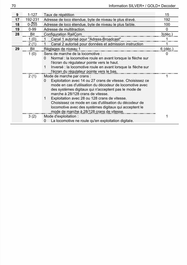
8/10/2019 GOLD SILVER Plus Manual
http://slidepdf.com/reader/full/gold-silver-plus-manual 69/80
F
CVValeur /
BitSignification
Réglaged'usine
1 1-127 Adresse de base de locomotive.
Ceci est le numéro avec lequel vous appelez la locomotive dansle système Digital plus by Lenz ®. Pour une utilisation avec lesappareils Digital plus by Lenz®, seules les adresses 1-99 sontpermises.Lors de l'écriture dans cette CV, l'adresse dans la CV 19(adresse de multitraction) et le bit 6 dans la CV 29 (utilisation del'adresse étendue) sont automatiquement effacés.
3
2 0-255 Tension minimale de démarrage. 13 0-255 Temporisation d'accélération. 64 0-255 Temporisation de freinage. 55 0-255 Vitesse maximale 2546 0-255 Vitesse moyenne Vmid 487 - Numéro de version.
SILVER+ (Art.Nr. 10331-01) 95
SILVER21+ (Art.Nr. 10321-01) 99SILVERdirect+ (Art.Nr. 10330-01) 98GOLD+ (Art.Nr. 10433-01) 91
8 - Code du constructeur. 99
70 Information SILVER+ / GOLD+ Decoder
9 1-127 Taux de répétition 1517 192-231 Adresse de loco étendue, byte de niveau le plus élevé. 192

8/10/2019 GOLD SILVER Plus Manual
http://slidepdf.com/reader/full/gold-silver-plus-manual 70/80
18 0-255 Adresse de loco étendue, byte de niveau le plus faible. 10019 0-99 Adresse de multitraction. 028 Bit Configuration RailCom 3(déc.)
1 (0) 1 Canal 1 autorisé pour "Adress-Broadcast" 12 (1) 1 Canal 2 autorisé pour données et admission instruction 1
29 Bit Réglages de niveau 1 6 (déc.)1 (0) Sens de marche de la locomotive :
0 Normal : la locomotive roule en avant lorsque la flèche surl'écran du régulateur pointe vers le haut.
1 Inversé : la locomotive roule en avant lorsque la flèche sur
l'écran du régulateur pointe vers le bas.
0
2 (1) Mode de marche par crans :0 Exploitation avec 14 ou 27 crans de vitesse. Choisissez ce
mode en cas d'utilisation du décodeur de locomotive avecdes systèmes digitaux qui n'acceptent pas le mode demarche à 28/128 crans de vitesse.
1
1 Exploitation avec 28 ou 128 crans de vitesse.
Choisissez ce mode en cas d'utilisation du décodeur delocomotive avec des systèmes digitaux qui acceptent lemode de marche à 28/128 crans de vitesse.
3 (2) Mode d'exploitation :0 La locomotive ne roule qu'en exploitation digitale.
1
71
1 La locomotive roule aussi bien en exploitationconventionnelle qu'en exploitation digitale ; le passage del' à l' t f it t ti t
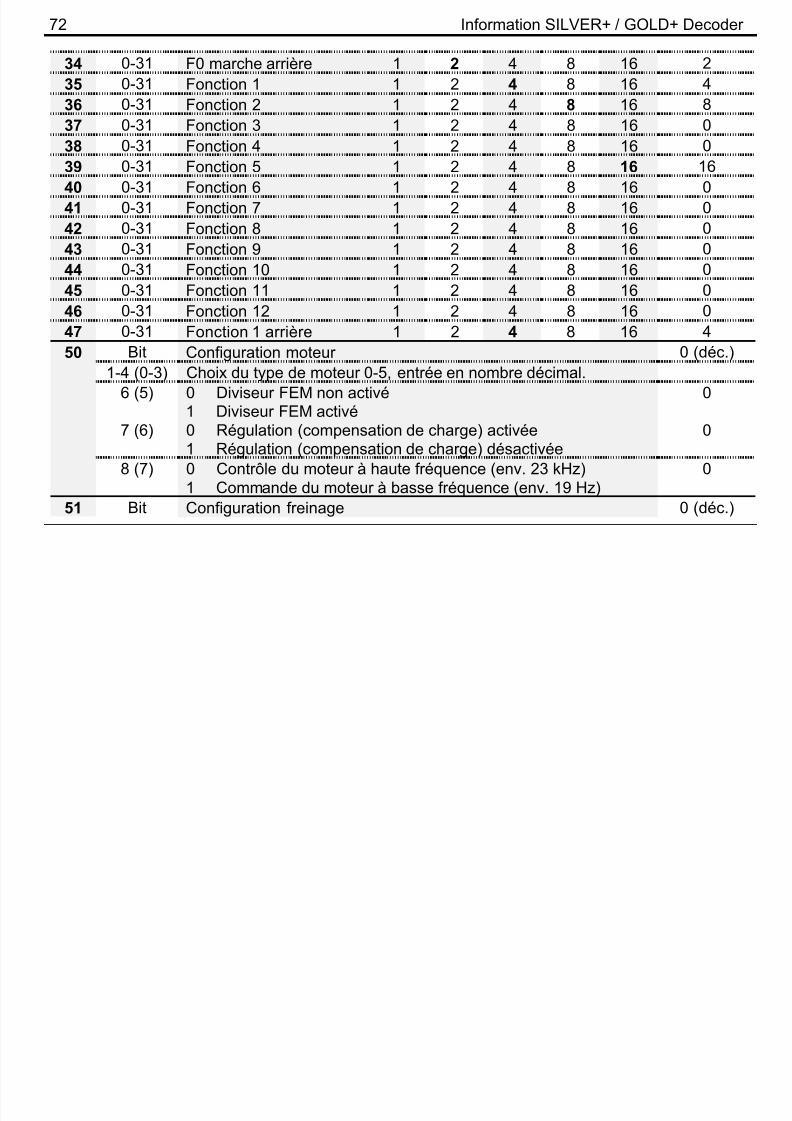
8/10/2019 GOLD SILVER Plus Manual
http://slidepdf.com/reader/full/gold-silver-plus-manual 71/80
F
l'une à l'autre se fait automatiquement.4 (3) 0 Envoi RailCom désactivé
1 Envoi RailCom activé0
5 (4) 0 Courbe caractéristique de vitesse encodée en usine1 Courbe caractériser. de vitesse définie par l'util isateur6 (5) 0 Le décodeur utilise l'adresse de base (en CV 1).
1 Le décodeur utilise l'adresse étendue (en CV 17 et 18).0
7-8 (6-7) Non utilisé. 030 Bit Annonce d'erreur 0 (déc.)
1 (0) 1 Court-circuit lampes 0
2 (1) 1 Surchauffe 03 (2) 1 Court-circuit moteur 0CV
33
–
47
Domainede
valeurs
Attribution des touches de fonction (mapping) aux sorties defonction :Pour attribuer une touche de fonction du système digital à unesortie de fonction, on cherche le point d'intersection de la lignedésignant la fonction souhaitée avec la colonne désignant lasortie de fonction souhaitée. Le nombre trouvé est introduit dansla CV correspondante. Les valeurs encodées en usine sontindiquées en gras.
Réglaged'usine
CV Sortie de fonction : A B C D E33 0-31 F0 marche avant 1 2 4 8 16 1
72 Information SILVER+ / GOLD+ Decoder
34 0-31 F0 marche arrière 1 2 4 8 16 235 0-31 Fonction 1 1 2 4 8 16 4

8/10/2019 GOLD SILVER Plus Manual
http://slidepdf.com/reader/full/gold-silver-plus-manual 72/80
36 0-31 Fonction 2 1 2 4 8 16 837 0-31 Fonction 3 1 2 4 8 16 038 0-31 Fonction 4 1 2 4 8 16 0
39 0-31 Fonction 5 1 2 4 8 16 1640 0-31 Fonction 6 1 2 4 8 16 041 0-31 Fonction 7 1 2 4 8 16 042 0-31 Fonction 8 1 2 4 8 16 043 0-31 Fonction 9 1 2 4 8 16 044 0-31 Fonction 10 1 2 4 8 16 045 0-31 Fonction 11 1 2 4 8 16 046 0-31 Fonction 12 1 2 4 8 16 047 0-31 Fonction 1 arrière 1 2 4 8 16 450 Bit Configuration moteur 0 (déc.)
1-4 (0-3) Choix du type de moteur 0-5, entrée en nombre décimal.6 (5) 0 Diviseur FEM non activé
1 Diviseur FEM activé0
7 (6) 0 Régulation (compensation de charge) activée1 Régulation (compensation de charge) désactivée 0
8 (7) 0 Contrôle du moteur à haute fréquence (env. 23 kHz)1 Commande du moteur à basse fréquence (env. 19 Hz)
0
51 Bit Configuration freinage 0 (déc.)
73
1 (0) 1 Distance de freinage constante activée en cas d'exploitation ABC.
0
2 (1) 1 ABC ti é 0

8/10/2019 GOLD SILVER Plus Manual
http://slidepdf.com/reader/full/gold-silver-plus-manual 73/80
F
2 (1) 1 ABC activé 03 (2) 1 Le mode "assujetti au sens de marche" de l'ABC est
désactivé0
4 (3) 1 Exploitation en navette sans arrêt intermédiaire activée 05 (4) 1 Exploitation en navette avec arrêt intermédiaire activée 06 (5) 1 Arrêter avec le courant continu indépendamment de la
polarité (n'est pris en compte que si le bit 3 est éteint dans laCV29)
0
7 (6) Bit non utilisés8 (7) Distance de freinage constante activée en cas de cran
de vitesse 0.
0
52 0-255 Longueur de freinage en cas de distance de freinage constanteactivée
50
53 0-255 Marche au ralenti en cas d'ABC activé 4854 0-255 Durée de l'arrêt en cas d'exploitation en navette activée : 1 à 256
sec.4
55 0-255 Règle la luminosité aux sorties de fonction A, 255 = max. 255
56 0-255 Règle la luminosité aux sorties de fonction B, 255 = max. 25557
-
59,
Attribution des fonctions (mapping):Chaque bit de la CV correspond à une fonction du systèmedigital : bit 1(0) pour fonction 1, bit 2(1) pour fonction 2 et ainsi desuite jusqu'au bit 8(7) pour fonction 8. Si vous désirez conférer le
74 Information SILVER+ / GOLD+ Decoder
61 dimming à une fonction, le bit concerné doit être inscrit.57 0-255 Dimming (réglage intensité) (aucun mapping n'est encodé en
usine)0

8/10/2019 GOLD SILVER Plus Manual
http://slidepdf.com/reader/full/gold-silver-plus-manual 74/80
usine)58 0-255 Mode manoeuvre (touche F3 encodée en usine) 459 0-255 Désactivation de la temporisation (touche F4 encodée en usine) 8
60 0-255 Effets lumineux aux sorties de fonction A et B: 0Le chiffre des dizaines vautpour la sortie B0 Aucun effet1 Marslight (gyrophare lent)2 Gyrolight (gyrophare
rapide)
3 Strobe (flash)4 Double strobe (doubleflash)
Le chiffre des unités vaut pourla sortie A0 Aucun effet1 Marslight (gyrophare lent)2 Gyrolight (gyrophare
rapide)
3 Strobe (flash)4 Double strobe (doubleflash)
61 0-255 Attribution des fonctions aux sorties de fonction A et B pour lacommande des effets lumineux
0
62 0-255 Effets lumineux aux sorties de fonction C et D. 0Chiffre des dizaines pour lasortie D :0 Aucun effet1 Clignotement en
synchronisme avec lasortie C
Chiffre des unités pour la sortieC :0 Aucun effet1 Clignotement2 Scintillement type 1
(calme)

8/10/2019 GOLD SILVER Plus Manual
http://slidepdf.com/reader/full/gold-silver-plus-manual 75/80
76 Information SILVER+ / GOLD+ Decoder
Attribution des touches de fonction F13 – F28 (mapping) auxsorties de fonction :
CV Sortie de fonction : A B C D E
8/10/2019 GOLD SILVER Plus Manual
http://slidepdf.com/reader/full/gold-silver-plus-manual 76/80
CV Sortie de fonction : A B C D E129 0-31 Fonction 13 1 2 4 8 16 0130 0-31 Fonction 14 1 2 4 8 16 0
131 0-31 Fonction 15 1 2 4 8 16 0132 0-31 Fonction 16 1 2 4 8 16 0133 0-31 Fonction 17 1 2 4 8 16 0134 0-31 Fonction 18 1 2 4 8 16 0135 0-31 Fonction 19 1 2 4 8 16 0136 0-31 Fonction 20 1 2 4 8 16 0137 0-31 Fonction 21 1 2 4 8 16 0138 0-31 Fonction 22 1 2 4 8 16 0139 0-31 Fonction 23 1 2 4 8 16 0140 0-31 Fonction 24 1 2 4 8 16 0141 0-31 Fonction 25 1 2 4 8 16 0142 0-31 Fonction 26 1 2 4 8 16 0143 0-31 Fonction 27 1 2 4 8 16 0
144 0-31 Fonction 28 1 2 4 8 16 0
77
145 0-7 Attribution d'une touche de fonction à la télécommande desattelages en marche avant.
0
Sortie de fonction : A B C D E

8/10/2019 GOLD SILVER Plus Manual
http://slidepdf.com/reader/full/gold-silver-plus-manual 77/80
F
Sortie de fonction : A B C D E1 2 4 8 16 0
146 0-7 Attribution d'une touche de fonction à la télécommande des
attelages en marche arrière.
0
Sortie de fonction : A B C D E1 2 4 8 16 0
147 0-255 La durée de pleine puissance est réglable sur une série devaleurs multiples de 0,016 secondes. Le réglage d'usinecorrespond à 30 x 0,016 s = 0,48 s.
30
148 0-255 L'avancement de la locomotive lors du dételage est réglable sur
une série de valeurs multiples de 0,016 secondes. Le réglaged'usine correspond à 80 x 0,016 s = 1,28 s.
80
78 Information SILVER+ / GOLD+ Decoder
Diese Seite ist absichtlich frei.
8/10/2019 GOLD SILVER Plus Manual
http://slidepdf.com/reader/full/gold-silver-plus-manual 78/80
79
Diese Seite ist absichtlich frei.

8/10/2019 GOLD SILVER Plus Manual
http://slidepdf.com/reader/full/gold-silver-plus-manual 79/80
F
80 Information SILVER+ / GOLD+ Decoder

8/10/2019 GOLD SILVER Plus Manual
http://slidepdf.com/reader/full/gold-silver-plus-manual 80/80
Vogelsang 14D - 35398 Gießen
Hotline: 06403 900 133
Fax: 06403 900 155http://www.digital-plus.de
http://www.lenz-elektronik.come-mail: [email protected]
Diese Betriebsanleitung bitte für späteren Gebrauch aufbewahren!Keep this operation manual for future reference!
Conservez ce manuel pour une utilisation ultérieure !