global companies section 10 and article 15 permit ... · global new windsor project town of new...
TRANSCRIPT

SECTION 10 AND ARTICLE 15 PERMIT APPLICATION
Global New Windsor Project River Road
Town of New Windsor Orange County
State Of New York
APPLICANT:
Global Companies LLC 800 South Street, Suite 200
Waltham, Massachusetts 02453
PREPARED BY:
Ingalls & Associates, LLP 2603 Guilderland Avenue
Schenectady, NY 12306 Phone: (518) 393-7725
Fax: (518) 393-2324
November 18, 2013

Global New Windsor Project Town of New Windsor, Orange County, New York Section 10 and Article 15 Permit Application Narrative 1
Table of Contents
1 INTRODUCTION ........................................................................................................................ 2 2 PROJECT DESCRIPTION .......................................................................................................... 2
2.1 Proposed Project ............................................................................................................................................................................ 2 2.2 Existing Conditions ....................................................................................................................................................................... 3 2.3 General Site Information ............................................................................................................................................................ 4
2.3.1 Land Use History .................................................................................................................................................................. 4 2.3.2 Existing Conditions Maps ................................................................................................................................................. 4 2.3.3 Watershed Information ..................................................................................................................................................... 4 2.3.4 Tributaries ............................................................................................................................................................................... 4 2.3.5 Wetland Connections with Tributaries ...................................................................................................................... 4 2.3.6 Tributary Connections to a Traditionally Navigable Water (TNW) ............................................................. 4 2.3.7 Distance to a TNW (Hudson River) .............................................................................................................................. 5 2.3.8 Tributary Substrate ............................................................................................................................................................. 5 2.3.9 Potential Pollutants ............................................................................................................................................................. 5 2.3.10 Potential Habitat ................................................................................................................................................................... 5 2.3.11 Isolated or Non-Jurisdictional Determinations ....................................................................................................... 5 2.3.12 Vegetative Cover Types ..................................................................................................................................................... 5 2.3.13 Wetland Delineation Forms ............................................................................................................................................. 5 2.3.14 Color Photographs ............................................................................................................................................................... 6 2.3.15 Soils ............................................................................................................................................................................................ 6
2.4 Project Purpose and Need ......................................................................................................................................................... 6 3 PROPOSED IMPACTS TO WATERS OF THE U.S. .............................................................. 7
3.1 Wetlands/Streams ........................................................................................................................................................................ 7 3.1.1 Wetlands .................................................................................................................................................................................. 7 3.1.2 Streams ..................................................................................................................................................................................... 8
3.2 Stormwater....................................................................................................................................................................................... 9 3.2.1 During Construction ............................................................................................................................................................ 9 3.2.2 Post Construction ................................................................................................................................................................. 9
4 ALTERNATIVES ANALYSIS ................................................................................................... 10 4.1 Null Alternative ............................................................................................................................................................................ 10 4.2 Selected Alternative.................................................................................................................................................................... 11
5 PERMITS TO BE AUTHORIZED BY THIS APPLICATION ............................................. 11 6 COASTAL ZONE MANAGEMENT PROGRAM .................................................................... 11 7 STATE OWNED LANDS UNDERWATER ............................................................................ 11 8 THREATENED OR ENDANGERED SPECIES ..................................................................... 11 9 CULTURAL AND HISTORIC RESOURCES (SECTION 106 NHPA) .............................. 14
APPENDICES A THROUGH H

Global New Windsor Project Town of New Windsor, Orange County, New York Section 10 and Article 15 Permit Application Narrative 2
1 INTRODUCTION
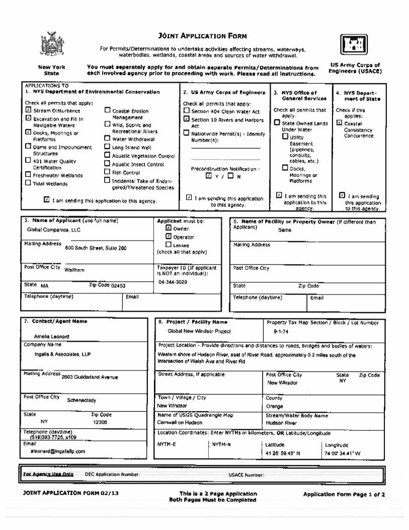
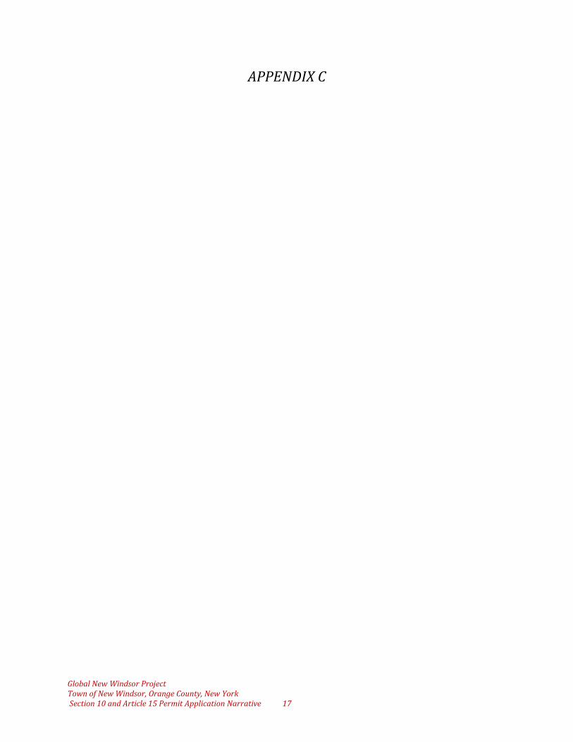
The following information has been provided in support of the Global New Windsor Project (“Project”) which will remediate contamination at a former shipyard along the Hudson River under the New York State Brownfields Cleanup Program, and redevelop the currently abandoned industrial site into a railcar transloading facility associated with three existing adjacent Major Oil Storage Facilities (MOSFs). These three MOSFs consist of the Global Newburgh, Global South and Global North Terminals. Additionally, the Project will include interconnection of petroleum storage amongst the three MOSFs and the railcar transloading facility via a pipe network, as well as expansion of an existing terminal dock at the Global North Terminal. The cumulative project site is comprised of four separate facilities located in an industrial zone south of the intersection of River Road and Walsh Avenue in the Town of New Windsor (“Town”), Orange County, New York. This narrative has been prepared under the direction of the Applicant and Project Sponsor, Global Companies LLC (“Global”), and has been submitted to the U.S. Army Corps of Engineers (USACE) in support of an Individual Permit Application in accordance with Section 10 of the Rivers and Harbors Act of 1899 (Section 10) to construct an expansion to an existing commercial dock within the Hudson River, a navigable water of the United States. This Application for the construction of a structure in a navigable water is pursuant to the requirements of Section 10 (33 U.S.C. 403). Additionally, this report has been submitted to the New York State Department of Environmental Conservation (NYSDEC) pursuant to Article 15, Title 5 of the New York State Environmental Conservation Law (ECL), “Stream Disturbance (Construction, reconstruction, or modification of certain docks, mooring areas or other structures in navigable waters)”.
2 PROJECT DESCRIPTION
2.1 Proposed Project
The proposed Project consists of the remediation and redevelopment of a former industrial shipyard into a railcar transloading facility under the New York Brownfields Cleanup Program (BCP); the interconnection of three separate MOSFs with one another and the railcar transloading facility; the construction of two marine Vapor Combustion Units (VCUs); and a 500 +/- square foot expansion of an existing terminal dock within the Hudson River. The Project site is comprised of four separate facilities located on River Road in the Town of New Windsor, south of the intersection with Walsh Avenue. It is situated east of River Road and west of the Hudson River and is bisected in a north-south direction by existing CSX rail lines. Portions of the subject properties include privately owned lands underwater, within the Hudson River. The brownfield remediation component of the Project is exempt from SEQRA pursuant to 6 NYCRR Part 617, as the Applicant will own and operate the brownfield site and has been accepted as a volunteer into the BCP. Therefore, the “action” for SEQRA purposes is the approvals needed for the redevelopment and operation of the remaining portions of the BCP Site and related improvements on the adjacent MOSF terminals. This document will assess the potential impacts associated with the Project. Once redeveloped, the railcar transloading property will receive petroleum liquids, biofuels, and/or ethanol (“products”) by rail and distribute those products to existing storage tanks located at adjacent NYSDEC-licensed MOSF terminals owned and operated by Global. Products will be distributed from the storage tanks at the MOSF terminals via the marine docks and truck loading racks at such terminals. Global currently owns three separate docks for the berthing and

Global New Windsor Project Town of New Windsor, Orange County, New York Section 10 and Article 15 Permit Application Narrative 3
loading/unloading operations of vessels, which are referenced from north to south, respectively, as: Newburgh Terminal Dock, North Terminal Dock, and South Terminal Dock. The proposed railcar transloading facility (the BCP Site) will be primarily located on a 25 +/- acre parcel located at 1220 River Road, between the Global South Terminal and the Global North Terminal. The Project consists of two basic parts: the brownfield cleanup and the project elements subject to SEQRA. The components of each of these parts are set forth below. Brownfield Cleanup Program Project Components:
• Demolition of existing structures at the 1220 River Road property. • Removal and off-site disposal, where necessary, of demolition materials. • Implementation of remediation to address soil impacts. • Installation of a cap to restrict access to impacted soils and portions of rail lines and
underground piping which are integral to the cap. The filing of an environmental easement on the former shipyard property, along with a site management plan with regard to future development as a result of site remediation.
Project Components Subject to SEQRA:
• Completion of above ground components (pipes, pump, etc.) on the 1220 River Road property and installation of pipelines and associated pumps to connect the rail area to existing terminal tankage.
• Installation of marine loading arms at the Global Newburgh Terminal and Global North Terminal docks.
• Installation of marine VCUs to control vapors from proposed marine loading operations. • Construction of an approximately 500 square foot expansion area of an existing dock to
support the required VCU at the Global North Terminal Dock. • Installation of steam and/or hot oil boilers for heating of rail cars and tanks. • Installation of internal floating roofs within existing bulk storage tanks to allow for storage
of products with higher levels of VOCs.
2.2 Existing Conditions
The Project will interconnect four separate facilities, which are or will be owned by Global. The four facilities (referenced from north to south) are as follows:
• Global Newburgh Terminal (9.52 +/- acres) • Global North Terminal (11.56 +/- acres) • Rail Facility Site (25.34 +/- acres) • Global South Terminal (19.13 +/- acres)
These four facilities are located on River Road, west of and extending into the Hudson River, approximately 0.25 miles south of the intersection of River Road and Walsh Avenue in the Town of New Windsor, Orange County, New York. The Project Sponsor is in the process of acquiring the 25 +/- acre Rail Facility Site parcel to incorporate into the overall development. The geographic coordinates of the approximate Center Point of the site are 41°28’34” N; 74°00’45” W.
The 25 +/- acre Rail Facility Site was operated historically as a shipyard and metals refinery until the late 1990s, when it was abandoned. Global (“Applicant”) has entered into a purchase and sale

Global New Windsor Project Town of New Windsor, Orange County, New York Section 10 and Article 15 Permit Application Narrative 4
agreement to acquire this property and a second property totaling 1.40 +/- acres located west of the Rail Facility Site, which is not part of the project. No activities will be conducted on the 1.40 +/- acre property. Site improvements on the Rail Facility Site will include the demolition of the existing buildings, excavation of historically contaminated soil, and construction of a multi-spur railcar transloading facility. Work on the Rail Facility Site will be completed under a Brownfields Cleanup Agreement (BCA) with the NYSDEC. The proposed rail spurs will tie into the existing CSX rail lines which bisect the Rail Facility Site.
The Rail Facility Site is comprised of areas of vacant undeveloped land along the western edge and the southeast corner of the site and several large, vacant industrial/storage buildings in an area zoned as planned industrial. Approximately 70% of the site is covered by hard packed gravel fill and/or structures associated with the site’s previous uses.
2.3 General Site Information
2.3.1 Land Use History
Since the mid-20th century, the subject properties and surrounding areas have been utilized for commercial and industrial uses, including historical shipbuilding activities and petroleum terminals. The existing terminal docks were constructed in the 1960s in have been operated by Texaco, Warex, and Global Petroleum Corp to offload petroleum products since they were constructed.
2.3.2 Existing Conditions Maps
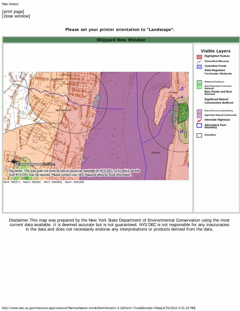
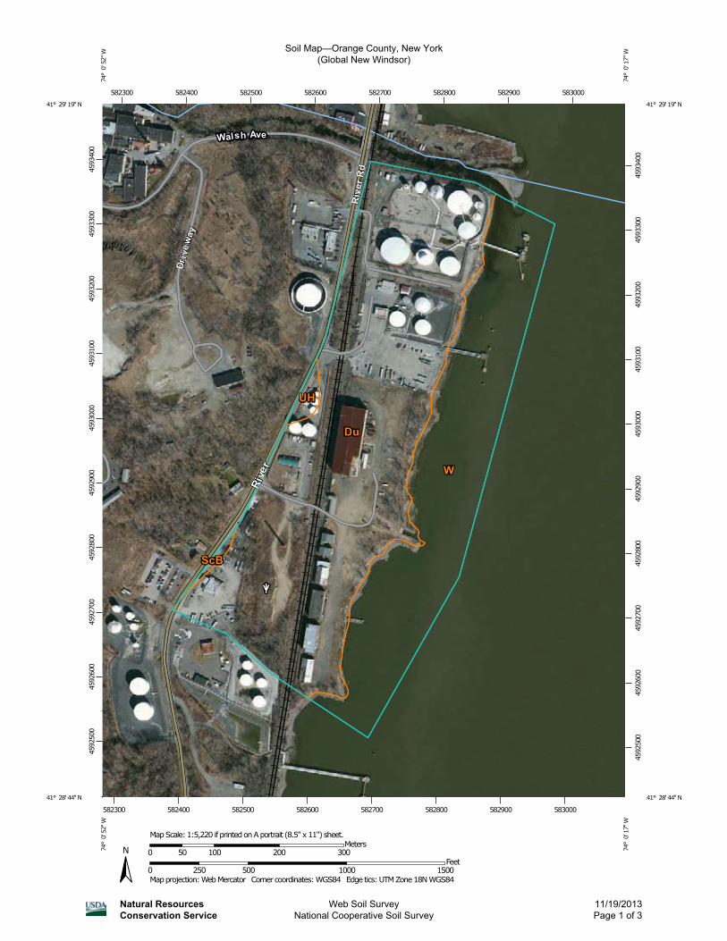
The appropriate NYSDEC Wetlands Map, National Wetland Inventory (NWI) Map, and Orange County Soil Survey Map are included within Appendix B of this document.
2.3.3 Watershed Information
2.3.3.1 HUC Code 02-02-0008
2.3.3.2 Watershed Size – 12,500 sq. miles
2.3.3.3 Drainage Area Size – 928 sq. miles
2.3.3.4 Average Annual Precipitation – 43.3”
2.3.4 Tributaries
The Project is immediately adjacent to and within the Hudson River, a Traditionally Navigable Water (TNW).
2.3.5 Wetland Connections with Tributaries
Two wetlands, totaling 0.54 acres, are present within the on-shore portion of the project site. Both wetlands area connected to the Hudson River, a TNW.
2.3.6 Tributary Connections to a Traditionally Navigable Water (TNW)
The Hudson River is a TNW.
Global New Windsor Project Town of New Windsor, Orange County, New York Section 10 and Article 15 Permit Application Narrative 5
2.3.7 Distance to a TNW (Hudson River)
2.3.7.1 River Miles – 0 miles
2.3.7.2 Aerial Miles – 0 miles
2.3.8 Tributary Substrate
The substrate of the Hudson River is primarily sand, gravel, and silt in this area.
2.3.9 Potential Pollutants
Because the project is within the Hudson River, which is known to be contaminated with PCBs in some areas, it is possible that contaminants exist in the vicinity of the site. However, proposed dock expansion will result in minimal disturbance below the mud line. Only pile driving and installation of fiberglass forms to construct pile jackets will result in sediment disturbance. All appropriate Best Management Practices shall be utilized to minimize suspension of sediment during driving of piles and fiberglass forms.
2.3.10 Potential Habitat
Both USFWS and NYSDEC Environmental Resource Maps are included within Appendix B of this document. The Hudson River south of the Troy Dam is known spawning habitat for the endangered species Shortnose Sturgeon (Acipenser brevirostrum) and Atlantic Sturgeon (Acipenser oxyrinchus). However, we expect the potential permit shall have seasonal restrictions to avoid impacting any threatened or endangered species. An Essential Fish Habitat Assessment and Endangered Species Consultation Report (EFH) has been prepared and is included within this submittal for coordination with the National Marine Fisheries Service (NMFS). Please refer to Section 8 of this document for additional information.
2.3.11 Isolated or Non-Jurisdictional Determinations
There are no isolated wetlands or previous Jurisdictional Determinations associated with the Project Site.
2.3.12 Vegetative Cover Types
There is no vegetative cover in the proposed dock expansion area. It is strictly underwater habitat, which experiences frequent barge traffic, limiting the growth of vegetation in the area of the proposed structure expansion. Much of the on-shore portion of the project site is covered by hard packed gravel and structures from historic shipbuilding activities. The southwestern portion of the site, including Wetland Area ‘B’, is forested. Refer to Section 3.1.1 of this document for additional detail.
2.3.13 Wetland Delineation Forms
Included within Appendix D of this document.

Global New Windsor Project Town of New Windsor, Orange County, New York Section 10 and Article 15 Permit Application Narrative 6
2.3.14 Color Photographs
Included within Appendix C of this document.
2.3.15 Soils
Soils throughout the site are mapped by the Natural Resources Conservation Service (NRCS) Orange County Soil Survey as partially hydric Dumps (Du) and Water (W).
Du – This unit consists of areas used for trash disposal. The areas are throughout the State, and most are on outwash terraces. Many of the dumps are adjacent to streams. Most range from 3 to 40 acres. Dumps are commonly called landfills or sanitary landfills. They consist mostly of trash from residential and commercial areas. The trash is largely composed of paper, cans, plastic, and bottles and is covered daily with soil material. The older parts of some dumps were commonly burned but not covered with soil material. A few dumps include industrial waste, tree stumps, car bodies, concrete, and debris from demolished buildings. Included with this unit in mapping are areas, generally less than 1 acre in size, of excessively drained Hinckley soils; somewhat excessively drained Merrimac soils; well drained Canton, Charlton and Narragansett soils; and Udorthents. Also included are a few small dumps that have bedrock outcrops and a few dumps along the larger streams that are subject to flooding. Dumps require onsite investigation and evaluation for land use decisions. A few dumps have been used for industrial sites. One of the major factors affecting use is the liquid that percolates through the material in the dumps.
2.4 Project Purpose and Need
The Project will provide for continued operation at the existing Terminals, and continue to provide a local source of petroleum products. Also, additional jobs for terminal operators and associated personnel will be generated as a result of the Project. From a larger economic perspective, constructing this facility will facilitate intermodal transportation of petroleum liquids, biofuels and/or ethanol to and from refineries and producers on the east coast and mid-continent regions of the United States using currently available infrastructure with minimal environmental impact.
Project development will also result in the subject Rail Facility Site being remediated in accordance with the NYSDEC Brownfields Cleanup Program to remove and remediate soil along the Hudson River, which was previously contaminated as a result of historic activities on site by an unrelated party. The subject site is currently vacant, with several dilapidated structures containing asbestos, which will be demolished and disposed of in accordance with all applicable laws, improving the aesthetics and safety of the site.

Global New Windsor Project Town of New Windsor, Orange County, New York Section 10 and Article 15 Permit Application Narrative 7
3 PROPOSED IMPACTS TO WATERS OF THE U.S.
3.1 Wetlands/Streams
3.1.1 Wetlands
In September of 2012, a team of qualified environmental professionals from Ingalls & Associates, LLP (Ingalls) reviewed the Rail Facility Site for the presence of state and/or federally regulated wetlands. Delineation of all wetland boundaries was conducted in accordance with the 2010 U.S. Army Corps of Engineers (USACE) Northcentral/Northeast Regional Supplement to the 1987 Wetland Delineation Manual, and all applicable NYSDEC procedures and protocols. This investigation included both office literature reviews of Orange County Soil Maps, NYSDEC Freshwater Wetland Maps, and U.S. Fish & Wildlife Service (USFWS) National Wetland Inventory Maps; as well as a field review/delineation. Wetland boundary flags were placed along the wetland/upland boundaries, and data sheets were prepared indicating the present vegetation, soil type, and hydrology for each distinctive area. Ingalls completed the survey location of wetland flags and prepared a Wetland Map. Two wetland areas were delineated on the Rail Facility Site, totaling 0.54+/- acres. Wetland A is located in the northeastern corner of the site at the top of the riverbank, eastward of the existing chain-link fence. Wetland B-C is located in the southwestern corner of the site, west of the existing railroad tracks, near the Global Newburgh South Terminal and carries drainage from offsite toward the river. The wetlands identified on-site are considered “waters of the U.S.” and are therefore federally jurisdictional and subject to regulation by the USACE. On-site wetlands do not appear to be considered New York State Freshwater Wetlands, as they are less than 12.4 acres in size and not of unusual local importance. As per the 2010 Corps of Engineers Northcentral/Northeast Regional Supplement to the 1987 Wetland Delineation Manual, an area must exhibit three characteristics to be deemed a wetland: hydric soils, wetland hydrology, and hydrophytic vegetation (>50% of dominant vegetative species within the area’s plant community must have an indicator status of FAC or wetter ). The on-site wetlands exhibit these three characteristics, and can thereby be classified as wetlands. The vegetation found within the on-site wetlands includes but is not limited to: red maple (Acer rubrum), box elder (Acer negundo), cottonwood (Populus deltoides), common buckthorn (Rhamnus cathartica), common reed (Phragmites australis), honey locust (Gleditsia triacanthos), field horsetail (Equisetum arvense), and pale swallow-wort (Cyanchum rossicum). The upland vegetation found on the property includes but is not limited to: cottonwood (Populus deltoides), honey locust (Gleditsia triacanthos), staghorn sumac (Rhus typhina), common reed (Phragmites australis), wild strawberry (Fragaria virginiana), Japanese knotweed (Polygonum cuspidatum), Virginia creeper (Parthenocissus quinquefolia), speckled alder (Alnus rugosa), quaking aspen (Populus tremuloides), common buckthorn (Rhamnus cathartica), silky dogwood (Cornus amomum), Canada goldenrod (Solidago canadensis), and field horsetail (Equisetum arvense). Consistent with NRCS Soils Maps, as well as historical topographic mapping, the entire Rail Facility Site appears to be gravel and refuse fill. Glass shards were encountered approximately 3 inches below the ground surface during attempted test pit digs located near Wetland A.
Global New Windsor Project Town of New Windsor, Orange County, New York Section 10 and Article 15 Permit Application Narrative 8
The entire project has been designed to avoid all on-site wetlands. Because the on-site wetlands are not considered state-regulated freshwater wetlands, no buffer requirement (adjacent area requirement) exists. No wetland impacts are proposed or necessary; therefore no mitigative measures are applicable.
3.1.2 Streams
3.1.2.1 Platform Construction Construction of the proposed rail spurs, and associated loading operations, necessitate implementation of air quality controls, including the installation of a dock safety unit (DSU), to comply with U.S. Coast Guard (USCG) regulations. This DSU must be installed at the dock (approximately 205’+/- from shore) to provide safety equipment to protect operating personnel and equipment. The DSU provides vessel over/under pressure protection, fire and explosion protection, and vapor conditioning in compliance with USCG regulations. Reference the documents in Appendix E entitled “Marine Vapor Emission Control Systems” prepared by John Zink and “The United States Coast Guard Requirements for Facility Marine Vapour Control Systems”, prepared by Sara S. Ju of the USCG for additional detail relative to the regulatory requirements and process.
Both the Newburgh Terminal Dock and the North Terminal Dock must have DSUs installed to comply with USCG regulations for barge loading operations. There is currently sufficient space at the Newburgh Terminal Dock to accommodate the dimensions of the required DSU. However, adequate space is not available at the existing North Terminal Dock and therefore the Applicant has proposed to construct an addition. The addition has been designed at the minimum dimensions necessary to support the required DSU. The Applicant proposes to construct a platform within the Hudson River measuring 32’ from east to west and 16’ from north to south, which will be supported by six steel H-piles driven into the river bottom and connected to the existing dock structure via a catwalk. Following installation of these piles, they will be jacketed to prevent corrosion using cast in place concrete and fiberglass forms. Please refer to Sheets 1 through 4 of the plans entitled “North Dock DSU Platform Addition”, prepared by Ingalls & Associates, LLP, dated August 28, 2013 in Appendix G for details regarding the proposed construction.
Potential stream impacts associated with the construction of the dock expansion are limited to driving and jacketing six steel piles. All other work to construct the dock shall be completed well above the plane of Mean High Water. No impacts to navigation will occur during or following construction of the dock, as the expansion area will be constructed landward of the existing terminal dock. Following construction, the only potential impact of the dock expansion will be bottom shading below the footprint of the dock.
3.1.2.2 Pile Jacketing for All Steel Pier Supports A corrosion protection system must be implemented for all of the steel H-piles supporting the pier and platform structures. Similar to the existing jacketed pile supports, pile jacketing with cast-in-place concrete with fiberglass forms will encapsulate the piles and provide for corrosion protection of the steel.
The H-piles shall be jacketed with cast-in-place concrete using fiberglass forms. The forms shall be driven to a minimum of 12” below the mud line. After forms are installed, #4 rebar shall be driven

Global New Windsor Project Town of New Windsor, Orange County, New York Section 10 and Article 15 Permit Application Narrative 9
evenly spaced between the perimeter of the existing H-piles and the fiberglass forms. Cast-in-place concrete shall be pumped into the forms and allowed to cure, then capped with cast-in-place grout.
Figure 1 - Not to Scale:
3.2 Stormwater
3.2.1 During Construction
All Best Management Practices shall be implemented during demolition, remediation, and construction to ensure sediment does not enter the river. A Construction Stormwater Pollution Prevention Plan (SWPPP) is being prepared in accordance with the NYS SPDES General Permit for Stormwater Discharges from Construction Activity (GP-0-10-001) and will be implemented throughout construction. SWPPP inspections by a qualified professional will be performed weekly during construction to observe and document stormwater management practices.
3.2.2 Post Construction
Impacts to stormwater runoff (i.e. impacts to surface waters from onsite drainage) are to be mitigated by the continued implementation of a site-specific Stormwater Management Plan, which has been updated to incorporate the proposed expansion area. This plan includes erosion and sediment control measures to address stormwater quality and quantity control, including on-site detention facilities to mitigate post-redevelopment runoff characteristics to pre-redevelopment levels. An Industrial Stormwater Management Plan is currently being prepared, including post-construction stormwater quality and quantity controls, for the long-term operational phase of the proposed rail spur area, to ensure post-construction runoff characteristics do not change as a result of the project. The Stormwater Management Plan will ensure compliance with the NYSDEC SPDES
Step 1: Install 24”Ø Fiberglass Form Surrounding H-Piles from 1’ Above Mean High Water to 1’ Below Mud Line
Step 2: Install #4 Rebar Evenly Spaced Surrounding Existing H-Piles
Step 3: Fill Fiberglass Forms with Cast-in-Place Concrete
Global New Windsor Project Town of New Windsor, Orange County, New York Section 10 and Article 15 Permit Application Narrative 10
Multi Sector General Permit for Stormwater Discharges from Industrial Activity (GP-0-12-001) prior to discharge. Preliminary stormwater design includes the construction of a new SPDES outfall pipe which will discharge treated industrial stormwater to the river, though the outfall will occur above the Mean High Water elevation, as shown on the attached “New Windsor (Phase 2) Fuel Unloading Facility, Proposed Grading Plan, Sheets 1 through 4 of 4”, prepared by stormwater design engineering firm Henningson, Durham, and Richardson Architecture and Engineering, P.C. (HDR) in Appendix H. There are two proposed outfalls to the Hudson River, neither of which is below the MHWM of the Hudson River. A SPDES permit application is being submitted for non-stormwater discharge associated with the boilers. The Rail Facility Site will operate under the Industrial General Permit until such time that the rail facility can be incorporated into an Individual Permit associated with the MOSF Terminals. During that time, the boiler discharge (boiler blowdown) will be containerized and disposed of off-site. Compliance with both the Construction SWPPP and Industrial Stormwater Management Plan will ensure that the proposed activities have no effect on the Hudson River.
4 ALTERNATIVES ANALYSIS
4.1 Null Alternative
The null alternative would prevent barge loading operations from occurring at the North Dock, as there is not sufficient space currently for DSU, which is required by state and federal air pollution control regulations. The Newburgh Dock can and will proceed with barge loading operations without dock expansion, but does not provide sufficient throughput or docking space to meet consumer demand. Unless the Applicant is able to expeditiously load barges with petroleum products, there is no reason to redevelop the abandoned shipyard to receive products via rail, nor is there any reason for the Applicant to purchase the property and proceed with site remediation under the Brownfields Cleanup Agreement, which we anticipate will be implemented imminently. When deciding between these two alternatives, it is necessary to understand that the proposed project will only have a minuscule impact on the Hudson River.
The area in which the dock expansion is proposed is immediately landward of an existing pile supported dock, which is currently utilized as an operating petroleum terminal dock. No impact to navigation will occur as a result of building the 512 square foot proposed dock, as it will be constructed landward of the existing platform. The only potential impact to the river bottom would be associated with driving six H-piles to support the dock expansion. All other construction will occur above the plane of Mean High Water. It is both mandated by regulation and necessary for safety to situate the proposed DSU at the terminus of the existing dock to facilitate barge loading operations; therefore, the proposed dock expansion is an essential requirement for the project to proceed.

Global New Windsor Project Town of New Windsor, Orange County, New York Section 10 and Article 15 Permit Application Narrative 11
4.2 Selected Alternative
The selected alternative is to construct the proposed dock, which is of the minimum dimensions necessary to support the proposed DSU and provide sufficient space to walk around the unit in the event maintenance is required. Again, proposed dock construction necessitates only driving six H-piles below the plane of Mean High Water. The potential impact to the river bottom (and therefore Essential Fish Habitat) is both small scale and temporary in nature. Additionally, proposed construction is immediately adjacent to a heavily trafficked operable petroleum terminal dock.
5 PERMITS TO BE AUTHORIZED BY THIS APPLICATION
• USACE Section 10 of the Rivers and Harbors Act (33 USC 403) Individual Permit • NYSDEC Article 15 Protection of Waters Permit (6NYCRR PART 608)
Authorization is required to construct a 32’ x 16’ expansion of an existing commercial dock to support a Dock Safety Unit mandated by state and federal regulation to perform barge loading of petroleum products. Six steel H-piles will be driven into the river bottom and jacketed with concrete. Two stormwater outfalls (above the plane of Mean High Water) shall be constructed to outlet collected stormwater from an intermodal rail facility in accordance with NYS SPDES regulations.
6 COASTAL ZONE MANAGEMENT PROGRAM
A Federal Consistency Assessment Form has been submitted to the New York State Department of State Coastal Management Program, as the proposed repairs will occur in the Coastal Zone. A copy of the FCAF has been included with this submittal. Further correspondence will be forwarded to your office upon receipt.
7 STATE OWNED LANDS UNDERWATER
According to Town of New Windsor Tax Maps, the Applicant’s property line extends into the Hudson River, beyond the face of the existing dock. Therefore, no state owned lands underwater will be affected by the proposed (landward) dock expansion.
8 THREATENED OR ENDANGERED SPECIES
This office utilized the USFWS Information, Planning, and Conservation System (IPAC) database to determine which species protected under the Federal Endangered Species Act might be present on

Global New Windsor Project Town of New Windsor, Orange County, New York Section 10 and Article 15 Permit Application Narrative 12
the site or affected by the proposed development. According to the IPAC report, the following species have the potential to be affected by a project located on the subject site:
o Dwarf Wedgemussel (Alasmidonta heterodon) o Small Whorled Pogonia (Isotria medeoloides) o Indiana Bat (Myotis sodalis) o Bog Turtle (Clemmys [=Glyptemys] muhlenbergii) o Shortnose Sturgeon (Acipenser brevirostrum) o Atlantic Sturgeon (Acipenser oxyrinchus)
This office has also reviewed the USFWS Northeast Biological Services Field Office’s list of species by county. According to that database, the following additional species has the potential to be located within Orange County, New York:
o Bald Eagle (Haliaeetus leucocephalus) (Though no longer protected by the Endangered Species Act, Bald Eagles are protected by the Bald Eagle Golden Eagle Protection Act)
A team of qualified biologists from Ingalls & Associates reviewed the site on September 13, 2012 to evaluate the project site for its suitability for habitat for any of the species listed above. Their findings indicate:
Dwarf Wedgemussel (Alasmidonta heterodon, Endangered) – Dwarf Wedgemussel populations in New York State are primarily limited to the Neversink River, a tributary of the Delaware River. While there is minimal potential for the Dwarf Wedgemussel to exist within the Hudson River, east of the proposed project site, the only work proposed within the Hudson River includes driving six steel H-piles below the mud line. All proper erosion and sediment control measures shall be implemented such that no turbid or contaminated discharge enters the river from the site. Therefore, the proposed project will not have any effect on the endangered Dwarf Wedgemussel.
Indiana Bat (Myotis sodalis, W/S - Endangered) ─ The potential for Indiana Bats to exist on-site is limited to nil due to the devastating effect of white-nosed syndrome on the population as a whole. According to the New York Natural Heritage Program’s website1, no hibernacula or maternity colonies have been identified within Orange County in recent years. However, bachelor colonies have been identified through radio-telemetry studies and mist-net captures in Orange County. Indiana Bats hibernate in caves and mines from October through April. Summer foraging habitat typically consists of wooded or semi-wooded riparian areas. Maternity colonies are typically within hollow trees or under loose bark of dead or dying trees with exfoliating bark, often exposed to direct sunlight. As there are no mines or caves on the subject site, there is no potential for hibernacula to exist onsite. Again, much of the site is covered by hard packed gravel and dilapidated industrial buildings, and is unvegetated. The minor vegetated portion of the site includes the 5.06 +/- acre parcel west of the railroad tracks, which is partially forested, but
1 New York Natural Heritage Program. 2011. Online Conservation Guide for Myotis sodalis. Available from: http://www.acris.nynhp.org/guide.php?id=7405. Accessed September 25th, 2012.
Global New Windsor Project Town of New Windsor, Orange County, New York Section 10 and Article 15 Permit Application Narrative 13
comprised of species including quaking aspen, red maple, buckthorn, honey locust, staghorn sumac, and box elder. This 5.06 +/- portion of the site will not be disturbed by proposed redevelopment. Typically, maternity colonies are found in shagbark hickory, or occasionally, dead black locust trees. The site was reviewed for potential Indiana Bat habitat by a qualified biologist, who investigated all trees greater than 9 inches diameter at breast height (DBH) that met the above criteria to determine their suitability to support Indiana Bats. Factors such as exfoliating bark, holes, cavities, and crevices were evaluated, and no suitable Indiana Bat habitat was encountered.
Bog Turtle (Clemmys [=Glyptemys] muhlenbergii, Threatened - Historic) –Because bog turtle habitat generally includes wetlands interspersed with dry and wet pockets, often with subsurface flow and shallow rivulets, as well as being spring-fed with shallow surface water or saturated soils present year-round, the wetlands on this site do not contain suitable hydrology for bog turtle habitat. In addition, typical bog turtle habitat contains a bottom substrate of permanently saturated organic or mineral soils, often soft, mucky-like or peat soils. As the on-site wetlands do not meet these criteria, they do not contain suitable soils for bog turtle habitat. Suitable bog turtle habitat vegetation often includes low grasses and sedges in emergent wetlands with tussocks and hummocks, often with a scrub-shrub wetland component. On-site wetlands do not exhibit tussocks or hummocks, nor do they meet the other criteria for bog turtle habitat. The site is therefore not suitable bog turtle habitat. (Bog Turtle Habitat Survey, USFWS)
Bald Eagle (Haliaeetus leucocephalus, Delisted) ─ Bald eagles utilize estuaries, large lakes, reservoirs, rivers, and some seacoasts for habitat and foraging. However, there is limited potential for Bald Eagles to exist on the proposed project site because there are no trees on site large enough to be suitable for their nesting habitat. Additionally, the subject site is sandwiched between two very active commercial petroleum terminals, and active rail lines transverse the entire site from north to south, which likely provide enough disturbances to deter bald eagles from utilizing the site for nesting. The site was evaluated visually for potential nesting habitat by a qualified biologist, and no potential habitat was located, nor was any evidence of eagle occupation observed.
Small Whorled Pogonia (Isotria medeoloides, Threatened) – According to USFWS, Orange County is the only county in New York State in which the Small Whorled Pogonia has been found in recent years. This orchid grows in older hardwood stands of beech, birch, maple, oak, and hickory that have an open understory. Sometimes it grows in stands of softwoods such as hemlock. It prefers acidic soils with a thick layer of dead leaves, often on slopes near small streams. As stated above, only a fraction of the subject site is vegetated. Moreover, the minimal vegetated area is dominated by species including quaking aspen, red maple, buckthorn, honey locust, staghorn sumac, and box elder, which are not typically conducive to Small Whorled Pogonia habitat. Additionally, vegetated areas of the subject site were field reviewed for the Small Whorled Pogonia; none were found.
Shortnose Sturgeon (Acipenser brevirostrum) and Atlantic Sturgeon (Acipenser oxyrinchus) – Because a portion of the proposed project includes the expansion of an existing dock within the Hudson River, an Essential Fish Habitat Assessment and Endangered Species Act Consultation report has been prepared and will be submitted to the National Marine Fisheries Service (NMFS) for review and evaluation. Disturbance of river bottom habitat will be limited to driving six steel piles to facilitate expansion of the existing dock platform. It is expected that time of year work

Global New Windsor Project Town of New Windsor, Orange County, New York Section 10 and Article 15 Permit Application Narrative 14
restrictions will be placed on any in-water construction activities to avoid the potential spawning period for both sturgeon species.
9 CULTURAL AND HISTORIC RESOURCES (SECTION 106 NHPA)
A Phase IA/IB Cultural Resource Survey was completed by Birchwood Archaeological Services in 2012, and a comprehensive report was submitted to the New York State Office of Parks, Recreation, and Historic Preservation (OPRHP) for review. Per letter dated August 13, 2013, OPRHP has asserted their opinion that the proposed project will have “No Adverse Impact upon projects in or eligible for inclusion in the National Register of Historic Places.”

Global New Windsor Project Town of New Windsor, Orange County, New York Section 10 and Article 15 Permit Application Narrative 15
APPENDIX A


Global New Windsor Project Town of New Windsor, Orange County, New York Section 10 and Article 15 Permit Application Narrative 16
APPENDIX B

Map Output
http://www.dec.ny.gov/resource-app/resource?ServiceName=erm&ClientVersion=3.1&Form=True&Encode=False[4/25/2012 4:31:22 PM]
[print page][close window]
Please set your printer orientation to "Landscape".
Shipyard New Windsor
MinX: 580371, MaxX: 585332, MinY: 4593955, MaxY: 4591848
Visible Layers
Disclaimer:This map was prepared by the New York State Department of Environmental Conservation using the most current data available. It is deemed accurate but is not guaranteed. NYS DEC is not responsible for any inaccuracies
in the data and does not necessarily endorse any interpretations or products derived from the data.
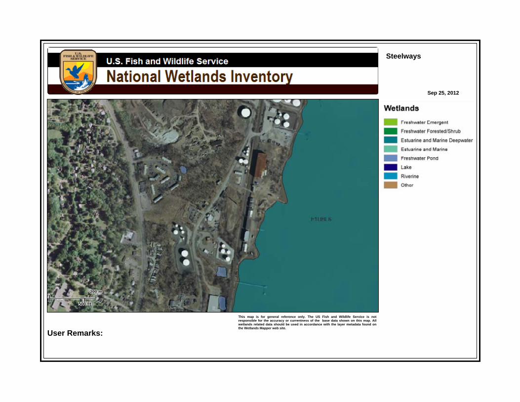
Steelways
Sep 25, 2012
This map is for general reference only. The US Fish and Wildlife Service is notresponsible for the accuracy or currentness of the base data shown on this map. Allwetlands related data should be used in accordance with the layer metadata found onthe Wetlands Mapper web site.
User Remarks:
Soil Map—Orange County, New York(Global New Windsor)
Natural ResourcesConservation Service
Web Soil SurveyNational Cooperative Soil Survey
11/19/2013Page 1 of 3
4592
500
4592
600
4592
700
4592
800
4592
900
4593
000
4593
100
4593
200
4593
300
4593
400
4592
500
4592
600
4592
700
4592
800
4592
900
4593
000
4593
100
4593
200
4593
300
4593
400
582300 582400 582500 582600 582700 582800 582900 583000
582300 582400 582500 582600 582700 582800 582900 583000
41° 29' 19'' N74
° 0
' 52'
' W41° 29' 19'' N
74° 0
' 17'
' W
41° 28' 44'' N
74° 0
' 52'
' W
41° 28' 44'' N
74° 0
' 17'
' W
N
Map projection: Web Mercator Corner coordinates: WGS84 Edge tics: UTM Zone 18N WGS840 250 500 1000 1500
Feet0 50 100 200 300
MetersMap Scale: 1:5,220 if printed on A portrait (8.5" x 11") sheet.

MAP LEGEND MAP INFORMATION
Area of Interest (AOI)Area of Interest (AOI)
SoilsSoil Map Unit Polygons
Soil Map Unit Lines
Soil Map Unit Points
Special Point FeaturesBlowout
Borrow Pit
Clay Spot
Closed Depression
Gravel Pit
Gravelly Spot
Landfill
Lava Flow
Marsh or swamp
Mine or Quarry
Miscellaneous Water
Perennial Water
Rock Outcrop
Saline Spot
Sandy Spot
Severely Eroded Spot
Sinkhole
Slide or Slip
Sodic Spot
Spoil Area
Stony Spot
Very Stony Spot
Wet Spot
Other
Special Line Features
Water FeaturesStreams and Canals
TransportationRails
Interstate Highways
US Routes
Major Roads
Local Roads
BackgroundAerial Photography
The soil surveys that comprise your AOI were mapped at 1:15,800.
Warning: Soil Map may not be valid at this scale.
Enlargement of maps beyond the scale of mapping can causemisunderstanding of the detail of mapping and accuracy of soil lineplacement. The maps do not show the small areas of contrastingsoils that could have been shown at a more detailed scale.
Please rely on the bar scale on each map sheet for mapmeasurements.
Source of Map: Natural Resources Conservation ServiceWeb Soil Survey URL: http://websoilsurvey.nrcs.usda.govCoordinate System: Web Mercator (EPSG:3857)
Maps from the Web Soil Survey are based on the Web Mercatorprojection, which preserves direction and shape but distortsdistance and area. A projection that preserves area, such as theAlbers equal-area conic projection, should be used if more accuratecalculations of distance or area are required.
This product is generated from the USDA-NRCS certified data as ofthe version date(s) listed below.
Soil Survey Area: Orange County, New YorkSurvey Area Data: Version 13, Sep 21, 2012
Soil map units are labeled (as space allows) for map scales 1:50,000or larger.
Date(s) aerial images were photographed: Mar 26, 2011—Apr 16,2012
The orthophoto or other base map on which the soil lines werecompiled and digitized probably differs from the backgroundimagery displayed on these maps. As a result, some minor shiftingof map unit boundaries may be evident.
Soil Map—Orange County, New York(Global New Windsor)
Natural ResourcesConservation Service
Web Soil SurveyNational Cooperative Soil Survey
11/19/2013Page 2 of 3

Map Unit Legend
Orange County, New York (NY071)
Map Unit Symbol Map Unit Name Acres in AOI Percent of AOI
Du Dumps 41.6 64.3%
ScB Scio silt loam, 3 to 8 percentslopes
0.2 0.4%
UH Udorthents, smoothed 0.6 0.9%
W Water 22.3 34.4%
Totals for Area of Interest 64.7 100.0%
Soil Map—Orange County, New York Global New Windsor
Natural ResourcesConservation Service
Web Soil SurveyNational Cooperative Soil Survey
11/19/2013Page 3 of 3
Global New Windsor Project Town of New Windsor, Orange County, New York Section 10 and Article 15 Permit Application Narrative 17
APPENDIX C

Global North Terminal 1254 River Road, Town of New Windsor Proposed Dock Expansion Area P a g e | 1
Photo 1 – View from existing dock platform looking westward toward proposed dock expansion area.
Photo 2 – View from existing catwalk looking eastward toward proposed dock expansion area.
Global North Terminal 1254 River Road, Town of New Windsor Proposed Dock Expansion Area P a g e | 2
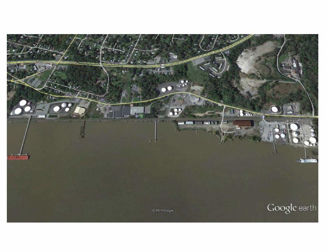
Photo 3 – View of North Terminal Dock looking southwest.
Photo 4 – View of North Terminal Dock looking westward.
Global North Terminal 1254 River Road, Town of New Windsor Proposed Dock Expansion Area P a g e | 3
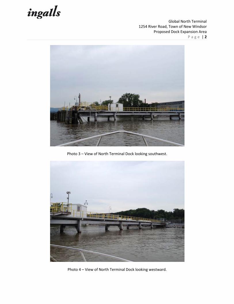
Photo 5 – View of federal Wetland Area A facing north.
Photo 6 – View of rail lines from southern edge of property facing north.
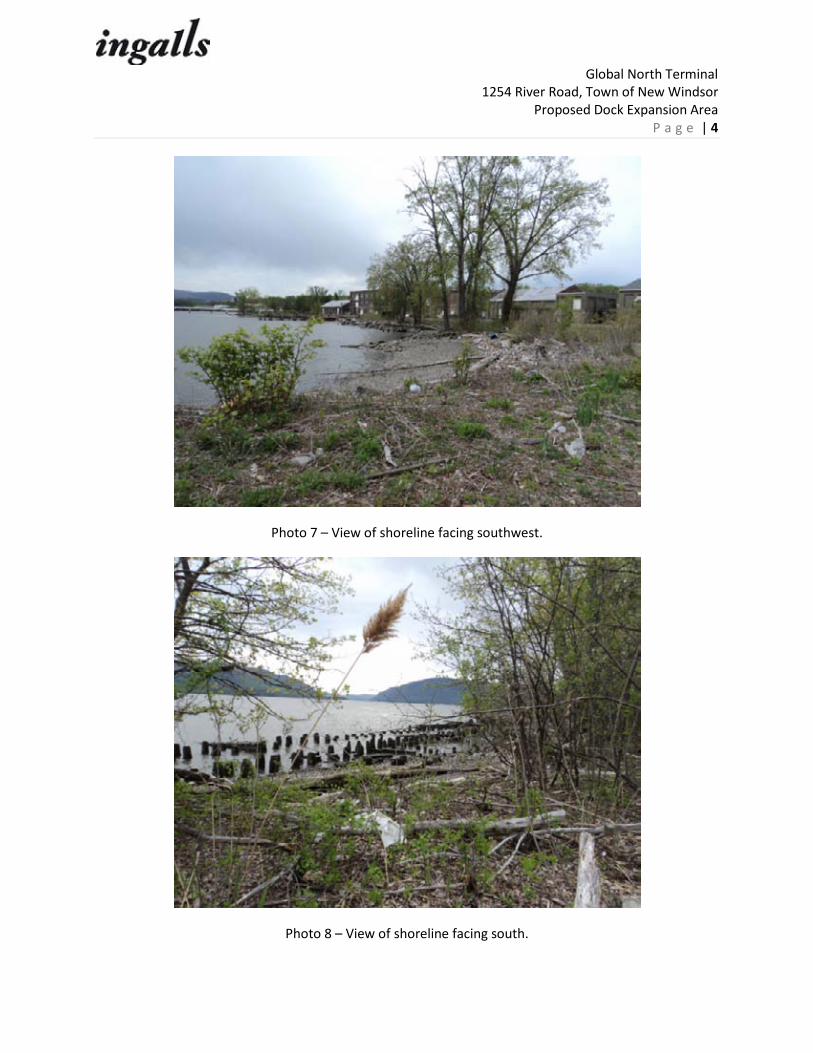
Global North Terminal 1254 River Road, Town of New Windsor Proposed Dock Expansion Area P a g e | 4
Photo 7 – View of shoreline facing southwest.
Photo 8 – View of shoreline facing south.
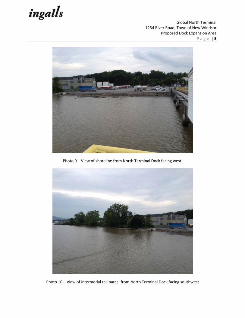
Global North Terminal 1254 River Road, Town of New Windsor Proposed Dock Expansion Area P a g e | 5
Photo 9 – View of shoreline from North Terminal Dock facing west.
Photo 10 – View of intermodal rail parcel from North Terminal Dock facing southwest

Global North Terminal 1254 River Road, Town of New Windsor Proposed Dock Expansion Area P a g e | 6
Photo 11 – View of surrounding industrial property north of subject site facing WSW.
Photo 12 – View of North Terminal Dock facing south

Global North Terminal 1254 River Road, Town of New Windsor Proposed Dock Expansion Area P a g e | 7
Photo 13 – View of shoreline of intermodal rail parcel from river facing SW.
Photo 14 – View of commercial/industrial activity south of intermodal rail parcel facing SSW.

Global North Terminal 1254 River Road, Town of New Windsor Proposed Dock Expansion Area P a g e | 8
Photo 15 – View of shoreline of intermodal rail facility facing SW.
Photo 16 – View of Global terminals facing north.


Global New Windsor Project Town of New Windsor, Orange County, New York Section 10 and Article 15 Permit Application Narrative 18
APPENDIX D

US Army Corps of Engineers Northcentral and Northeast Region – Interim Version
WETLAND DETERMINATION DATA FORM – Northcentral and Northeast Region Project/Site: City/County: Sampling Date:
Applicant/Owner: State: Sampling Point:
Investigator(s): Section, Township, Range:
Landform (hillslope, terrace, etc.): Local relief (concave, convex, none):
Slope (%): Lat: Long: Datum:
Soil Map Unit Name: NWI classification:
Are climatic / hydrologic conditions on the site typical for this time of year? Yes No (If no, explain in Remarks.)
Are Vegetation , Soil , or Hydrology significantly disturbed? Are “Normal Circumstances” present? Yes No
Are Vegetation , Soil , or Hydrology naturally problematic? (If needed, explain any answers in Remarks.)
SUMMARY OF FINDINGS – Attach site map showing sampling point locations, transects, important features, etc.
Hydrophytic Vegetation Present? Yes No Hydric Soil Present? Yes No Wetland Hydrology Present? Yes No
Is the Sampled Area within a Wetland? Yes No
If yes, optional Wetland Site ID: Remarks: (Explain alternative procedures here or in a separate report.)
HYDROLOGY Wetland Hydrology Indicators: Secondary Indicators (minimum of two required) Primary Indicators (minimum of one is required; check all that apply) Surface Soil Cracks (B6) Surface Water (A1) Water-Stained Leaves (B9) Drainage Patterns (B10) High Water Table (A2) Aquatic Fauna (B13) Moss Trim Lines (B16) Saturation (A3) Marl Deposits (B15) Dry-Season Water Table (C2) Water Marks (B1) Hydrogen Sulfide Odor (C1) Crayfish Burrows (C8) Sediment Deposits (B2) Oxidized Rhizospheres on Living Roots (C3) Saturation Visible on Aerial Imagery (C9) Drift Deposits (B3) Presence of Reduced Iron (C4) Stunted or Stressed Plants (D1) Algal Mat or Crust (B4) Recent Iron Reduction in Tilled Soils (C6) Geomorphic Position (D2) Iron Deposits (B5) Thin Muck Surface (C7) Shallow Aquitard (D3) Inundation Visible on Aerial Imagery (B7) Other (Explain in Remarks) Microtopographic Relief (D4) Sparsely Vegetated Concave Surface (B8) FAC-Neutral Test (D5) Field Observations: Surface Water Present? Yes No Depth (inches): Water Table Present? Yes No Depth (inches): Saturation Present? Yes No Depth (inches): (includes capillary fringe)
Wetland Hydrology Present? Yes No
Describe Recorded Data (stream gauge, monitoring well, aerial photos, previous inspections), if available:
Remarks:

US Army Corps of Engineers Northcentral and Northeast Region – Interim Version
VEGETATION – Use scientific names of plants. Sampling Point:
Dominance Test worksheet: Number of Dominant Species That Are OBL, FACW, or FAC: (A) Total Number of Dominant Species Across All Strata: (B) Percent of Dominant Species That Are OBL, FACW, or FAC: (A/B)
Prevalence Index worksheet: Total % Cover of: Multiply by: OBL species x 1 = FACW species x 2 = FAC species x 3 = FACU species x 4 = UPL species x 5 = Column Totals: (A) (B)
Prevalence Index = B/A =
Hydrophytic Vegetation Indicators: Rapid Test for Hydrophytic Vegetation Dominance Test is >50% Prevalence Index is ≤3.01 Morphological Adaptations1 (Provide supporting data in Remarks or on a separate sheet) Problematic Hydrophytic Vegetation1 (Explain) 1Indicators of hydric soil and wetland hydrology must be present, unless disturbed or problematic.
Definitions of Vegetation Strata: Tree – Woody plants 3 in. (7.6 cm) or more in diameter at breast height (DBH), regardless of height. Sapling/shrub – Woody plants less than 3 in. DBH and greater than 3.28 ft (1 m) tall. Herb – All herbaceous (non-woody) plants, regardless of size, and woody plants less than 3.28 ft tall. Woody vines – All woody vines greater than 3.28 ft in height.
Absolute Dominant Indicator Tree Stratum (Plot size: ) % Cover Species? Status
1.
2.
3.
4.
5.
6.
7.
= Total Cover
Sapling/Shrub Stratum (Plot size: )
1.
2.
3.
4.
5.
6.
7.
= Total Cover
Herb Stratum (Plot size: )
1.
2.
3.
4.
5.
6.
7.
8.
9.
10.
11.
12.
= Total Cover
Woody Vine Stratum (Plot size: )
1.
2.
3.
4.
= Total Cover
Hydrophytic Vegetation Present? Yes No
Remarks: (Include photo numbers here or on a separate sheet.)

US Army Corps of Engineers Northcentral and Northeast Region – Interim Version
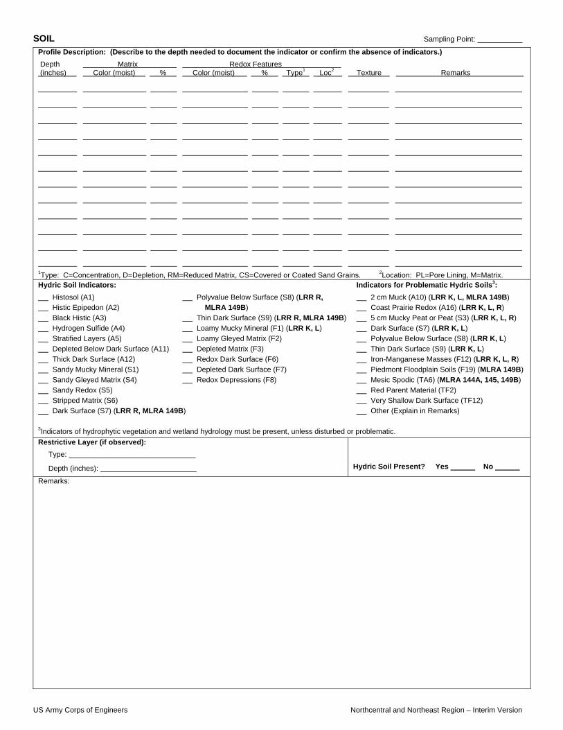
SOIL Sampling Point:
Profile Description: (Describe to the depth needed to document the indicator or confirm the absence of indicators.) Depth Matrix Redox Features (inches) Color (moist) % Color (moist) % Type1 Loc2 Texture Remarks
1Type: C=Concentration, D=Depletion, RM=Reduced Matrix, CS=Covered or Coated Sand Grains. 2Location: PL=Pore Lining, M=Matrix. Hydric Soil Indicators: Indicators for Problematic Hydric Soils3: Histosol (A1) Polyvalue Below Surface (S8) (LRR R, 2 cm Muck (A10) (LRR K, L, MLRA 149B) Histic Epipedon (A2) MLRA 149B) Coast Prairie Redox (A16) (LRR K, L, R) Black Histic (A3) Thin Dark Surface (S9) (LRR R, MLRA 149B) 5 cm Mucky Peat or Peat (S3) (LRR K, L, R) Hydrogen Sulfide (A4) Loamy Mucky Mineral (F1) (LRR K, L) Dark Surface (S7) (LRR K, L) Stratified Layers (A5) Loamy Gleyed Matrix (F2) Polyvalue Below Surface (S8) (LRR K, L) Depleted Below Dark Surface (A11) Depleted Matrix (F3) Thin Dark Surface (S9) (LRR K, L) Thick Dark Surface (A12) Redox Dark Surface (F6) Iron-Manganese Masses (F12) (LRR K, L, R) Sandy Mucky Mineral (S1) Depleted Dark Surface (F7) Piedmont Floodplain Soils (F19) (MLRA 149B) Sandy Gleyed Matrix (S4) Redox Depressions (F8) Mesic Spodic (TA6) (MLRA 144A, 145, 149B) Sandy Redox (S5) Red Parent Material (TF2) Stripped Matrix (S6) Very Shallow Dark Surface (TF12) Dark Surface (S7) (LRR R, MLRA 149B) Other (Explain in Remarks) 3Indicators of hydrophytic vegetation and wetland hydrology must be present, unless disturbed or problematic. Restrictive Layer (if observed): Type:
Depth (inches):
Hydric Soil Present? Yes No
Remarks:

US Army Corps of Engineers Northcentral and Northeast Region – Interim Version
WETLAND DETERMINATION DATA FORM – Northcentral and Northeast Region Project/Site: City/County: Sampling Date:
Applicant/Owner: State: Sampling Point:
Investigator(s): Section, Township, Range:
Landform (hillslope, terrace, etc.): Local relief (concave, convex, none):
Slope (%): Lat: Long: Datum:
Soil Map Unit Name: NWI classification:
Are climatic / hydrologic conditions on the site typical for this time of year? Yes No (If no, explain in Remarks.)
Are Vegetation , Soil , or Hydrology significantly disturbed? Are “Normal Circumstances” present? Yes No
Are Vegetation , Soil , or Hydrology naturally problematic? (If needed, explain any answers in Remarks.)
SUMMARY OF FINDINGS – Attach site map showing sampling point locations, transects, important features, etc.
Hydrophytic Vegetation Present? Yes No Hydric Soil Present? Yes No Wetland Hydrology Present? Yes No
Is the Sampled Area within a Wetland? Yes No
If yes, optional Wetland Site ID: Remarks: (Explain alternative procedures here or in a separate report.)
HYDROLOGY Wetland Hydrology Indicators: Secondary Indicators (minimum of two required) Primary Indicators (minimum of one is required; check all that apply) Surface Soil Cracks (B6) Surface Water (A1) Water-Stained Leaves (B9) Drainage Patterns (B10) High Water Table (A2) Aquatic Fauna (B13) Moss Trim Lines (B16) Saturation (A3) Marl Deposits (B15) Dry-Season Water Table (C2) Water Marks (B1) Hydrogen Sulfide Odor (C1) Crayfish Burrows (C8) Sediment Deposits (B2) Oxidized Rhizospheres on Living Roots (C3) Saturation Visible on Aerial Imagery (C9) Drift Deposits (B3) Presence of Reduced Iron (C4) Stunted or Stressed Plants (D1) Algal Mat or Crust (B4) Recent Iron Reduction in Tilled Soils (C6) Geomorphic Position (D2) Iron Deposits (B5) Thin Muck Surface (C7) Shallow Aquitard (D3) Inundation Visible on Aerial Imagery (B7) Other (Explain in Remarks) Microtopographic Relief (D4) Sparsely Vegetated Concave Surface (B8) FAC-Neutral Test (D5) Field Observations: Surface Water Present? Yes No Depth (inches): Water Table Present? Yes No Depth (inches): Saturation Present? Yes No Depth (inches): (includes capillary fringe)
Wetland Hydrology Present? Yes No
Describe Recorded Data (stream gauge, monitoring well, aerial photos, previous inspections), if available:
Remarks:

US Army Corps of Engineers Northcentral and Northeast Region – Interim Version
VEGETATION – Use scientific names of plants. Sampling Point:
Dominance Test worksheet: Number of Dominant Species That Are OBL, FACW, or FAC: (A) Total Number of Dominant Species Across All Strata: (B) Percent of Dominant Species That Are OBL, FACW, or FAC: (A/B)
Prevalence Index worksheet: Total % Cover of: Multiply by: OBL species x 1 = FACW species x 2 = FAC species x 3 = FACU species x 4 = UPL species x 5 = Column Totals: (A) (B)
Prevalence Index = B/A =
Hydrophytic Vegetation Indicators: Rapid Test for Hydrophytic Vegetation Dominance Test is >50% Prevalence Index is ≤3.01 Morphological Adaptations1 (Provide supporting data in Remarks or on a separate sheet) Problematic Hydrophytic Vegetation1 (Explain) 1Indicators of hydric soil and wetland hydrology must be present, unless disturbed or problematic.
Definitions of Vegetation Strata: Tree – Woody plants 3 in. (7.6 cm) or more in diameter at breast height (DBH), regardless of height. Sapling/shrub – Woody plants less than 3 in. DBH and greater than 3.28 ft (1 m) tall. Herb – All herbaceous (non-woody) plants, regardless of size, and woody plants less than 3.28 ft tall. Woody vines – All woody vines greater than 3.28 ft in height.
Absolute Dominant Indicator Tree Stratum (Plot size: ) % Cover Species? Status
1.
2.
3.
4.
5.
6.
7.
= Total Cover
Sapling/Shrub Stratum (Plot size: )
1.
2.
3.
4.
5.
6.
7.
= Total Cover
Herb Stratum (Plot size: )
1.
2.
3.
4.
5.
6.
7.
8.
9.
10.
11.
12.
= Total Cover
Woody Vine Stratum (Plot size: )
1.
2.
3.
4.
= Total Cover
Hydrophytic Vegetation Present? Yes No
Remarks: (Include photo numbers here or on a separate sheet.)

US Army Corps of Engineers Northcentral and Northeast Region – Interim Version
SOIL Sampling Point:
Profile Description: (Describe to the depth needed to document the indicator or confirm the absence of indicators.) Depth Matrix Redox Features (inches) Color (moist) % Color (moist) % Type1 Loc2 Texture Remarks
1Type: C=Concentration, D=Depletion, RM=Reduced Matrix, CS=Covered or Coated Sand Grains. 2Location: PL=Pore Lining, M=Matrix. Hydric Soil Indicators: Indicators for Problematic Hydric Soils3: Histosol (A1) Polyvalue Below Surface (S8) (LRR R, 2 cm Muck (A10) (LRR K, L, MLRA 149B) Histic Epipedon (A2) MLRA 149B) Coast Prairie Redox (A16) (LRR K, L, R) Black Histic (A3) Thin Dark Surface (S9) (LRR R, MLRA 149B) 5 cm Mucky Peat or Peat (S3) (LRR K, L, R) Hydrogen Sulfide (A4) Loamy Mucky Mineral (F1) (LRR K, L) Dark Surface (S7) (LRR K, L) Stratified Layers (A5) Loamy Gleyed Matrix (F2) Polyvalue Below Surface (S8) (LRR K, L) Depleted Below Dark Surface (A11) Depleted Matrix (F3) Thin Dark Surface (S9) (LRR K, L) Thick Dark Surface (A12) Redox Dark Surface (F6) Iron-Manganese Masses (F12) (LRR K, L, R) Sandy Mucky Mineral (S1) Depleted Dark Surface (F7) Piedmont Floodplain Soils (F19) (MLRA 149B) Sandy Gleyed Matrix (S4) Redox Depressions (F8) Mesic Spodic (TA6) (MLRA 144A, 145, 149B) Sandy Redox (S5) Red Parent Material (TF2) Stripped Matrix (S6) Very Shallow Dark Surface (TF12) Dark Surface (S7) (LRR R, MLRA 149B) Other (Explain in Remarks) 3Indicators of hydrophytic vegetation and wetland hydrology must be present, unless disturbed or problematic. Restrictive Layer (if observed): Type:
Depth (inches):
Hydric Soil Present? Yes No
Remarks:

US Army Corps of Engineers Northcentral and Northeast Region – Interim Version
WETLAND DETERMINATION DATA FORM – Northcentral and Northeast Region Project/Site: City/County: Sampling Date:
Applicant/Owner: State: Sampling Point:
Investigator(s): Section, Township, Range:
Landform (hillslope, terrace, etc.): Local relief (concave, convex, none):
Slope (%): Lat: Long: Datum:
Soil Map Unit Name: NWI classification:
Are climatic / hydrologic conditions on the site typical for this time of year? Yes No (If no, explain in Remarks.)
Are Vegetation , Soil , or Hydrology significantly disturbed? Are “Normal Circumstances” present? Yes No
Are Vegetation , Soil , or Hydrology naturally problematic? (If needed, explain any answers in Remarks.)
SUMMARY OF FINDINGS – Attach site map showing sampling point locations, transects, important features, etc.
Hydrophytic Vegetation Present? Yes No Hydric Soil Present? Yes No Wetland Hydrology Present? Yes No
Is the Sampled Area within a Wetland? Yes No
If yes, optional Wetland Site ID: Remarks: (Explain alternative procedures here or in a separate report.)
HYDROLOGY Wetland Hydrology Indicators: Secondary Indicators (minimum of two required) Primary Indicators (minimum of one is required; check all that apply) Surface Soil Cracks (B6) Surface Water (A1) Water-Stained Leaves (B9) Drainage Patterns (B10) High Water Table (A2) Aquatic Fauna (B13) Moss Trim Lines (B16) Saturation (A3) Marl Deposits (B15) Dry-Season Water Table (C2) Water Marks (B1) Hydrogen Sulfide Odor (C1) Crayfish Burrows (C8) Sediment Deposits (B2) Oxidized Rhizospheres on Living Roots (C3) Saturation Visible on Aerial Imagery (C9) Drift Deposits (B3) Presence of Reduced Iron (C4) Stunted or Stressed Plants (D1) Algal Mat or Crust (B4) Recent Iron Reduction in Tilled Soils (C6) Geomorphic Position (D2) Iron Deposits (B5) Thin Muck Surface (C7) Shallow Aquitard (D3) Inundation Visible on Aerial Imagery (B7) Other (Explain in Remarks) Microtopographic Relief (D4) Sparsely Vegetated Concave Surface (B8) FAC-Neutral Test (D5) Field Observations: Surface Water Present? Yes No Depth (inches): Water Table Present? Yes No Depth (inches): Saturation Present? Yes No Depth (inches): (includes capillary fringe)
Wetland Hydrology Present? Yes No
Describe Recorded Data (stream gauge, monitoring well, aerial photos, previous inspections), if available:
Remarks:

US Army Corps of Engineers Northcentral and Northeast Region – Interim Version
VEGETATION – Use scientific names of plants. Sampling Point:
Dominance Test worksheet: Number of Dominant Species That Are OBL, FACW, or FAC: (A) Total Number of Dominant Species Across All Strata: (B) Percent of Dominant Species That Are OBL, FACW, or FAC: (A/B)
Prevalence Index worksheet: Total % Cover of: Multiply by: OBL species x 1 = FACW species x 2 = FAC species x 3 = FACU species x 4 = UPL species x 5 = Column Totals: (A) (B)
Prevalence Index = B/A =
Hydrophytic Vegetation Indicators: Rapid Test for Hydrophytic Vegetation Dominance Test is >50% Prevalence Index is ≤3.01 Morphological Adaptations1 (Provide supporting data in Remarks or on a separate sheet) Problematic Hydrophytic Vegetation1 (Explain) 1Indicators of hydric soil and wetland hydrology must be present, unless disturbed or problematic.
Definitions of Vegetation Strata: Tree – Woody plants 3 in. (7.6 cm) or more in diameter at breast height (DBH), regardless of height. Sapling/shrub – Woody plants less than 3 in. DBH and greater than 3.28 ft (1 m) tall. Herb – All herbaceous (non-woody) plants, regardless of size, and woody plants less than 3.28 ft tall. Woody vines – All woody vines greater than 3.28 ft in height.
Absolute Dominant Indicator Tree Stratum (Plot size: ) % Cover Species? Status
1.
2.
3.
4.
5.
6.
7.
= Total Cover
Sapling/Shrub Stratum (Plot size: )
1.
2.
3.
4.
5.
6.
7.
= Total Cover
Herb Stratum (Plot size: )
1.
2.
3.
4.
5.
6.
7.
8.
9.
10.
11.
12.
= Total Cover
Woody Vine Stratum (Plot size: )
1.
2.
3.
4.
= Total Cover
Hydrophytic Vegetation Present? Yes No
Remarks: (Include photo numbers here or on a separate sheet.)
US Army Corps of Engineers Northcentral and Northeast Region – Interim Version
SOIL Sampling Point:
Profile Description: (Describe to the depth needed to document the indicator or confirm the absence of indicators.) Depth Matrix Redox Features (inches) Color (moist) % Color (moist) % Type1 Loc2 Texture Remarks
1Type: C=Concentration, D=Depletion, RM=Reduced Matrix, CS=Covered or Coated Sand Grains. 2Location: PL=Pore Lining, M=Matrix. Hydric Soil Indicators: Indicators for Problematic Hydric Soils3: Histosol (A1) Polyvalue Below Surface (S8) (LRR R, 2 cm Muck (A10) (LRR K, L, MLRA 149B) Histic Epipedon (A2) MLRA 149B) Coast Prairie Redox (A16) (LRR K, L, R) Black Histic (A3) Thin Dark Surface (S9) (LRR R, MLRA 149B) 5 cm Mucky Peat or Peat (S3) (LRR K, L, R) Hydrogen Sulfide (A4) Loamy Mucky Mineral (F1) (LRR K, L) Dark Surface (S7) (LRR K, L) Stratified Layers (A5) Loamy Gleyed Matrix (F2) Polyvalue Below Surface (S8) (LRR K, L) Depleted Below Dark Surface (A11) Depleted Matrix (F3) Thin Dark Surface (S9) (LRR K, L) Thick Dark Surface (A12) Redox Dark Surface (F6) Iron-Manganese Masses (F12) (LRR K, L, R) Sandy Mucky Mineral (S1) Depleted Dark Surface (F7) Piedmont Floodplain Soils (F19) (MLRA 149B) Sandy Gleyed Matrix (S4) Redox Depressions (F8) Mesic Spodic (TA6) (MLRA 144A, 145, 149B) Sandy Redox (S5) Red Parent Material (TF2) Stripped Matrix (S6) Very Shallow Dark Surface (TF12) Dark Surface (S7) (LRR R, MLRA 149B) Other (Explain in Remarks) 3Indicators of hydrophytic vegetation and wetland hydrology must be present, unless disturbed or problematic. Restrictive Layer (if observed): Type:
Depth (inches):
Hydric Soil Present? Yes No
Remarks:

Global New Windsor Project Town of New Windsor, Orange County, New York Section 10 and Article 15 Permit Application Narrative 19
APPENDIX E

PORT TECHNOLOGY INTERNATIONAL 109
LIQUID, CHEMICALAND GAS HANDLING
During marine tank vessel loading and other operations that introduce cargo or liquid into vessel cargo tanks, vapours, mostly volatile organic compounds (VOC), emit from the cargo tanks because of displacement and vapour growth. Under the authority of US Clean Air Act Amendments of 1990 (CAAA 90), the US Environmental Protection agency (EPA) has issued two sets of national standards for marine loading facilities designated as major sources to collect VOC and hazardous air pollutants displaced from marine tank vessels during loading and to reduce the captured vapours by 95 per cent to 98 per cent by weight. These standards do not address vessel unloading operations. The EPA also requires collection of vapours displaced from marine tank vessel cargo tanks during loading of cargoes containing 70 per cent or more benzene by weight. Many US States have adopted the EPA standards and issued regulations, similar with EPA standards, requiring major terminals to control vapours emitted from vessel cargo tanks during various marine tank vessel operations. Also under the authority of CAAA 90, the US Coast Guard in 1990 issued safety regulations for marine vapour control systems (VCSs). The majority of these regulations are contained in 33 CFR part 154, subpart E (for facilities) and 46 CFR part 36 (for vessels).
US Coast Guard Marine VCS requirements for transfer facilities Currently, marine terminals in 23 US states have about 250 VCSs installed and certified as meeting the US Coast Guard requirements for facility marine VCSs. The majority of these systems are located in the States of Texas, Louisiana, California, and New Jersey. Most of these systems use a flare for vapour destruction. Tank vessels visiting these facilities are required to have a vessel VCS meeting the US Coast Guard requirements for transferring vapours emitted from cargo tanks to the facility’s VCS for processing.
A typical facility marine VCS consists of a vapour collection system and a vapour processing unit. In most cases, vapours emitted from a tank vessel’s cargo tanks are collected by the tank vessel’s vapour collection system and sent to the facility’s VCS for processing. Methods used to process the captured vapours include recovery (absorption, adsorption, refrigeration), combustion (open flair, incinerator), or balancing (returning the vapours to facility storage tanks being emptied). A facility VCS may also contain these major equipment: pressure and temperature sensors, a relief valves, an emergency shutoff valve, detonation arresters and flame arresters, a liquid knock out pot, vapour moving devices, oxygen or hydrocarbon analysers, a liquid seal, and a vapour enriching, inerting, or diluting system. Controlling flammable and combustible cargo vapours presents numerous hazards including cargo tank overfill, overpressure or vacuum, cargo spillage, and fire and detonation of the flammable vapours. Because the EPA standards apply to marine facilities rather than to marine vessels, facilities are required to protect tank vessels from those hazards.
33 CFR 154 subpart E addresses the safe design and operational aspects of a transfer facility VCS used to control vapour of crude oil, gasoline blends, or benzene emitted from vessel cargo tanks. It focuses on the following areas:
• Liquid overfill protection
• Overpressure and vacuum protection
• Fire, explosion and detonation protection
• Requirements for inerting, enriching and diluting systems
• Vapour compressors and blowers
• Vapour recovery and vapour destruction systems
• Personnel training and operating requirements
• Design, performance, and testing standards for detonation and flame arresters
The United States Coast Guard requirements for facility marine vapour control systemsSara S. Ju, Senior Chemical Engineer, Hazardous Materials Standards Division, United States Coast Guard, Washington, DC, USA
Dock safety unit with required safety equipment at the dock.
Required MVCS equipment at the inlet of a vapour flare.

110 PORT TECHNOLOGY INTERNATIONAL www.porttechnology.org
LIQUID, CHEMICALAND GAS HANDLING
The VCS regulations require that a facility VCS which collects vapours of flammable or combustible cargoes other than crude oil, gasoline blends or benzene, must meet the requirements prescribed by the Commandant of the US Coast Guard. These requirements are contained in a US Coast Guard policy letter, 16703/33-154, dated May 5, 1992. This policy letter waives the fire, explosion and detonation protection requirements for VCSs controlling vapours of Grade E cargoes, and cargoes having a closed cup flash point greater than 60° C. It addresses cargo compatibility and cargo specific oxygen/hydrocarbon analyser alarm and shutdown setpoints. The current regulations require inerting systems to alarm or shut down when oxygen concentration in the vapour line exceeds 8.0 per cent or 9.0 per cent by volume respectively. For enriching systems, the regulations require system alarm, or shutdown, when hydrocarbon concentration in the vapour line falls below 170 per cent, or 150 per cent, by volume of the upper Flammable limits (UFL). This letter generalises inert systems’ alarm and shutdown setpoints to 60 per cent and 70 per cent by volume of the minimum oxygen concentration for combustion of the combination of cargo vapours and inerting gas. For enriching systems controlling vapours of cargoes with an UFL too high to operate under the 170 per cent and 150 per cent by volume requirements, this letter allows system alarm or shutdown, when hydrocarbon concentration falls below UFL + 10 per cent points, or UFL + 7.5 per cent points, respectively. This letter also requires VCSs that control vapours of high freezing point cargoes to be designed to prevent freezing of vapour or condensate at ambient temperatures and VCSs that control vapours of cargoes with the potential to polymerise to be equipped to detect polymer buildup.
33 CFR 154 subpart E delegates the authority of certifying facility VCSs to private, third-party, certifying entities accepted by the US Coast Guard. This programme allows marine facilities to hire and pay, at their choices, a Coast Guard authorised certifying
entity who can best accommodate their needs to conduct the VCS certification on behalf of the Coast Guard. The Coast Guard has established an oversight programme, and issued guidelines to these certifying entities to maintain technical control and quality assurance over the VCS certification programme.
Common exemptions granted by the US Coast Guard to facility VCSs The existing Coast Guard facility marine VCS regulations were developed based on a simple system. Since their issuance in 1990, VCS technologies have advanced and VCSs have become more sophisticated and complicated. Very often, facilities have to request for exemptions from the regulations for their VCS design and installation. The following are the most common exemptions granted:
• Allowing for installation of a dock safety skid, which usually contains a dock detonation arrester and an inerting or enriching gas injection point, at distances greater the regulatory requirements of six meters, and ten meters respectively, from the facility vapour connection to accommodate small and crowded docks. The extra length of vapour piping upstream of the detonation arrester should be well protected.
• Allowing facilities to install anti-flashback burners inside a vapour flare in lieu of a liquid seal at the inlet to the flare. To be granted with an exemption, the facility has to show good test results of the anti-flashback burners and installed thermocouples at the anti-flashback element which will activate system alarm and shutdown when high temperatures are detected.
• Allowing the use of flame arresters tested under industry standards. As a condition of the exemption, facilities have to install an additional safety measure, such as an analyser at the VCS outlet to monitor hydrocarbon concentration continuously and activate system alarm and shutdown.
Vapour piping and a vapour recovery unit.

PORT TECHNOLOGY INTERNATIONAL 111
LIQUID, CHEMICALAND GAS HANDLING
Other important exemptions granted include multi-breasted tandem barge loading, alternate VCS instruments test programmes, and cargo line clear ing (pigging) operations to tank vessels while connected to a VCS if a Coast Guard approved pigging system is used.
Other developmentsSeveral US States require vapour control at tank barge cleaning facilities during gas freeing and cargo tank cleaning operations. The US Coast Guard has issued a Navigation and Vessel Inspection Circular (NVIC), No. 1-96 to provide safety guidelines for design and operation of a marine VCS at tank barge cleaning facilities.
For the most part, the guidelines follow the requirements in the 33 CFR 154 subpart E for crude oil, gasoline blends, and benzene and incorporate the Coast Guard policies for controlling vapours of other flammable and combustible cargoes.
The US Coast Guard is in the process of revising its marine VCS regulations. The revised regulations would incorporate existing Coast Guard’s VCS policies, guidelines, clarifications, and exemptions granted which have general application to other VCSs. The revised regulations would also incorporate NVIC No. 1-96 and the Coast Guard guidelines provided to facility VCS certifying entities that clarify the minimum review and testing requirements of VCS certifications and re-certifications.
The US Coast Guard developed its existing VCS regulations, NVIC No. 1-96, and the proposed revised VCS regulations from recommendations provided by the Chemical Transportation Advisory Committee, which is a chaptered US Federal advisory committee advising the US Coast Guard on matters related to marine transportation of hazardous material in bulk. Its members are appointed by the US Secretary of Homeland Security and are all subject matter experts and industrial representatives.
Ms Sara Sing Ju is a Senior Chemical Engineer of
the Hazardous Materials Standards Division in US
Coast Guard Headquarters. She is responsible for the
development of regulations, guidelines, and policies
and the review of design exemptions, for marine
vapour control systems. Ms. Ju holds a B.S. degree in
chemical engineering and a M.S. degree in engineer
– environmental.
The Hazardous Materials Standards Division of the US
Coast Guard Headquarters develops regulations,
policies, standards, and guidelines to promote the
safety of life and protection of property and the
environment during marine transportation of
hazardous materials.
Commandant (CG-3PSO-3)
US Coast Guard
2100 Second Street, S.W.
Washington, DC 20593-0001
USA
Email: [email protected]
Website: http://homeport.uscg.mil/
ABOUT THE AUTHOR ABOUT THE ORGANISATION ENQUIRIES
ACKNOWLEDGEMENT
A typical dock safety skid with required MVCS equipment at the dock.

Marine Vapor eMissionControl systeMs
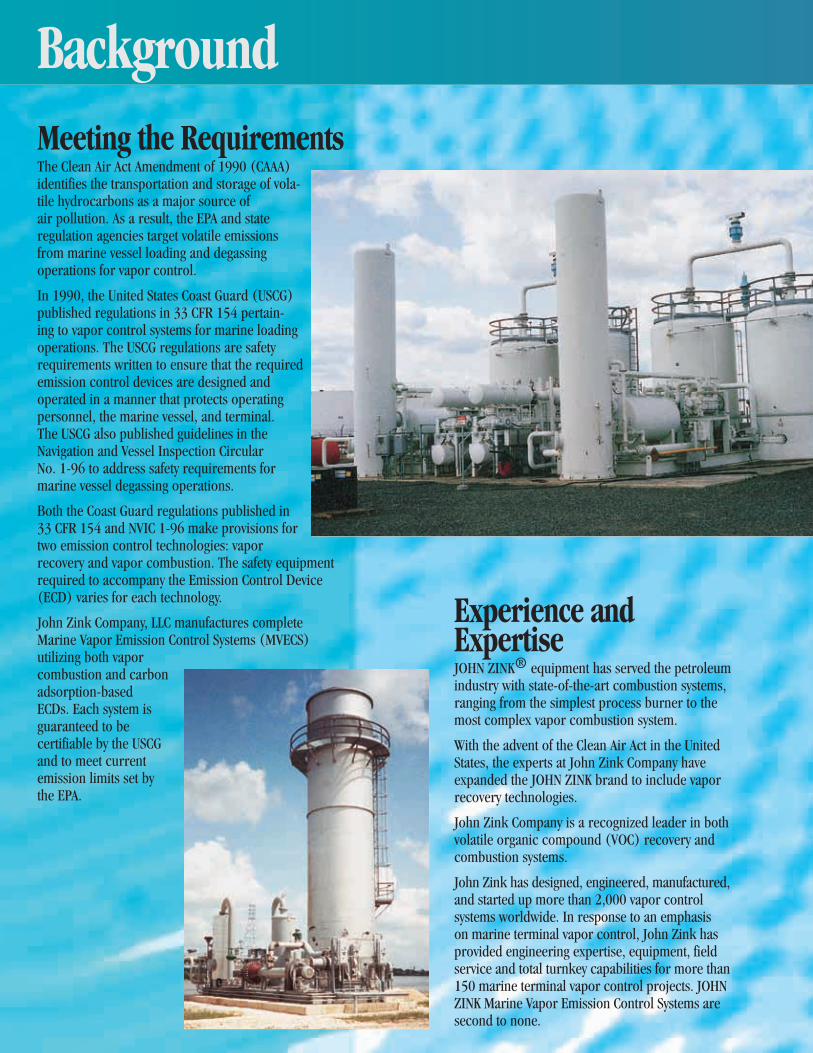
Meeting the RequirementsThe Clean Air Act Amendment of 1990 (CAAA) identifies the transportation and storage of vola-tile hydrocarbons as a major source of air pollution. As a result, the EPA and state regulation agencies target volatile emissions from marine vessel loading and degassing operations for vapor control.
In 1990, the United States Coast Guard (USCG) published regulations in 33 CFR 154 pertain-ing to vapor control systems for marine loading operations. The USCG regulations are safety requirements written to ensure that the required emission control devices are designed and operated in a manner that protects operating personnel, the marine vessel, and terminal. The USCG also published guidelines in the Navigation and Vessel Inspection Circular No. 1-96 to address safety requirements for marine vessel degassing operations.
Both the Coast Guard regulations published in 33 CFR 154 and NVIC 1-96 make provisions for two emission control technologies: vapor recovery and vapor combustion. The safety equipment required to accompany the Emission Control Device (ECD) varies for each technology.
John Zink Company, LLC manufactures complete Marine Vapor Emission Control Systems (MVECS) utilizing both vapor combustion and carbon adsorption-based ECDs. Each system is guaranteed to be certifiable by the USCG and to meet current emission limits set by the EPA.
Background
Experience and ExpertiseJohN ZINk® equipment has served the petroleum industry with state-of-the-art combustion systems, ranging from the simplest process burner to the most complex vapor combustion system.
With the advent of the Clean Air Act in the United States, the experts at John Zink Company have expanded the JohN ZINk brand to include vapor recovery technologies.
John Zink Company is a recognized leader in both volatile organic compound (VoC) recovery and combustion systems.
John Zink has designed, engineered, manufactured, and started up more than 2,000 vapor control systems worldwide. In response to an emphasis on marine terminal vapor control, John Zink has provided engineering expertise, equipment, field service and total turnkey capabilities for more than 150 marine terminal vapor control projects. JohN ZINk Marine Vapor Emission Control Systems are second to none.

BackgroundCustomized Modular DesignThe JohN ZINk modularized marine vapor control system removes the uncertainty of a new design, while allowing for specific customer requirements to be incorporated into the system. Customer benefits from this approach are numerous.
• Single source responsibility for the entire vapor control system.
• Assurance of compatibility of the control system with all components.
• Proven technology.
• Complete system checkout prior to delivery to assure 100% functionality and minimize on-site startup and certification time.
• Modules are assembled on skids and prewired to skid-edge terminal strips to eliminate expensive field construction and wiring costs.
• Common spare parts throughout the system.
• Every component/module/system is guaranteed to meet USCG requirements/guidelines.
John Zink Company Provides The Complete Spectrum In Marine Terminal Vapor Control:
Systems, Components, Services, Parts
MVECSMajor Components• Emission control devices - Recovery - Combustion• Dock safety units• Vapor blower units• Integrated control systems
Support Services• Economic comparisons of the technologies• Preliminary design and related cost estimates• Detailed system design• HAZOP review assistance• USCG certification assistance• Startup and performance testing• Preventive maintenance and emergency call-out service• Permit assistance• Installation
Packaged Systems
www.johnz ink.com

The heart of any Marine Vapor Emission Control System is the Emission Control Device. The regulations are written around the use of two Emission Control Devices: the Vapor Combustion System and the Vapor Recovery System. Either system can be used to meet the current federal emission regulations.
The selection of which ECD is best suited for a particular marine loading terminal is based on many factors. Some of these factors include: equipment cost, value of recovered products, availability and cost of fuel gas, availability and cost of electricity, plot plan requirements, overhead clearances, weight restrictions, compatibility of products loaded, insurance requirements, and secondary pollutants.
John Zink Company will be happy to evaluate the specific conditions at your terminal to determine the best technical and commercial solution.
Emission Control DevicesVapor Combustion SystemsJohn Zink Company offers several combustion technologies to cost effectively handle a broad range of vapor compositions, flow rates, and destruction efficiencies. our Vapor Combustion Units (VCUs) vary from the simplest open flame flare unit to a more complicated temperature-controlled enclosed combustion system. This control technology, along with the JohN ZINk vapor recovery technology, has been recognized by the U.S. EPA as both the Best Demonstrated Technology (BDT) and as the Maximum Achievable Control Technology (MACT) for terminal applications.
JohN ZINk VCUs have been installed in more than 1,000 loca-tions worldwide and are designed to safely burn air/hydrocarbon and inert gas/hydrocarbon mixtures generated from marine operations. Some safety features of the JohN ZINk VCU include anti-flashback burners, detonation arrestor, and automatic shut-down valves. In addition, burner velocity control is incorporated into the design to enhance the turndown capability of the system. Destruction efficiencies for these systems typically exceed 99%.
All marine VCU designs are guaranteed to meet the USCG safety requirements. When utilized for marine vapor control, JohN ZINk VCUs offer the following advantages to the end user:
• Low capital cost compared to alternatives with equal control efficiency.
• operation simplicity.
• Low maintenance cost.
• Capable of simultaneously handling multiple chemicals.
• Fuel savings features for temperature controlled units.
For more information regarding vapor combustion systems refer to the JohN ZINk Vapor Combustion Systems brochure.

Vapor Recovery SystemsJohn Zink Company offers Vapor Recovery Systems as an attractive alternative technology for marine hydrocarbon vapor emission control applications. The JohN ZINk technology was originally applied to the recovery of evaporative hydrocarbon vapor emissions at gasoline bulk distribution terminals. It was based on the combination of carbon adsorption and liquid absorption processes and was called Adsorption-Absorption (ADAB™). This technology has been recognized by the U.S. EPA as both the Best Demonstrated Technology (BDT) and as the Maximum Achievable Control Technology (MACT) for this application. over the last several years many improvements have been made and innovative optional features have been added to the basic system so that today, JohN ZINk Vapor Recovery Systems are applied worldwide to the recovery of a wide range of hydrocarbon vapors in a variety of applications.
The technology consists of a three-step process. Activated carbon adsorbs the hydrocarbon vapor component from the air-vapor feed stream allowing purified air to vent to the atmosphere. The carbon bed is regenerated by vacuum, which removes the previously adsorbed hydrocarbon vapor. This hydrocarbon vapor, removed from the carbon bed by the
regeneration process, is then recovered as a liquid product by absorption into a suitable liquid absorbent or, in some applications, by direct condensation. Recovery efficiencies for these systems typically exceed 99%.
When applied to marine vapor control applications, JohN ZINk Vapor Recovery Systems are designed in accordance with USCG safety requirements and often offer several advantages over alternative combustion-based vapor destruction technologies. These advantages include:
• Ability to be installed in a hazardous area which can reduce the cost of the vapor collection piping.
• Value of the recovered product offers a positive rate of return.
• No trade-off pollutants (oxides of nitrogen, carbon monoxide, carbon dioxide, etc.) are produced.
• Vapor conditioning (enriching, inerting, diluting) and associated equipment are not required.
• No supplemental fuel is needed to maintain minimum required combustion temperature during periods of low vapor flow and/or lean vapor concentrations.
For more information regarding vapor recovery systems refer to the JohN ZINk Vapor Recovery Systems brochure.
www.johnz ink.com
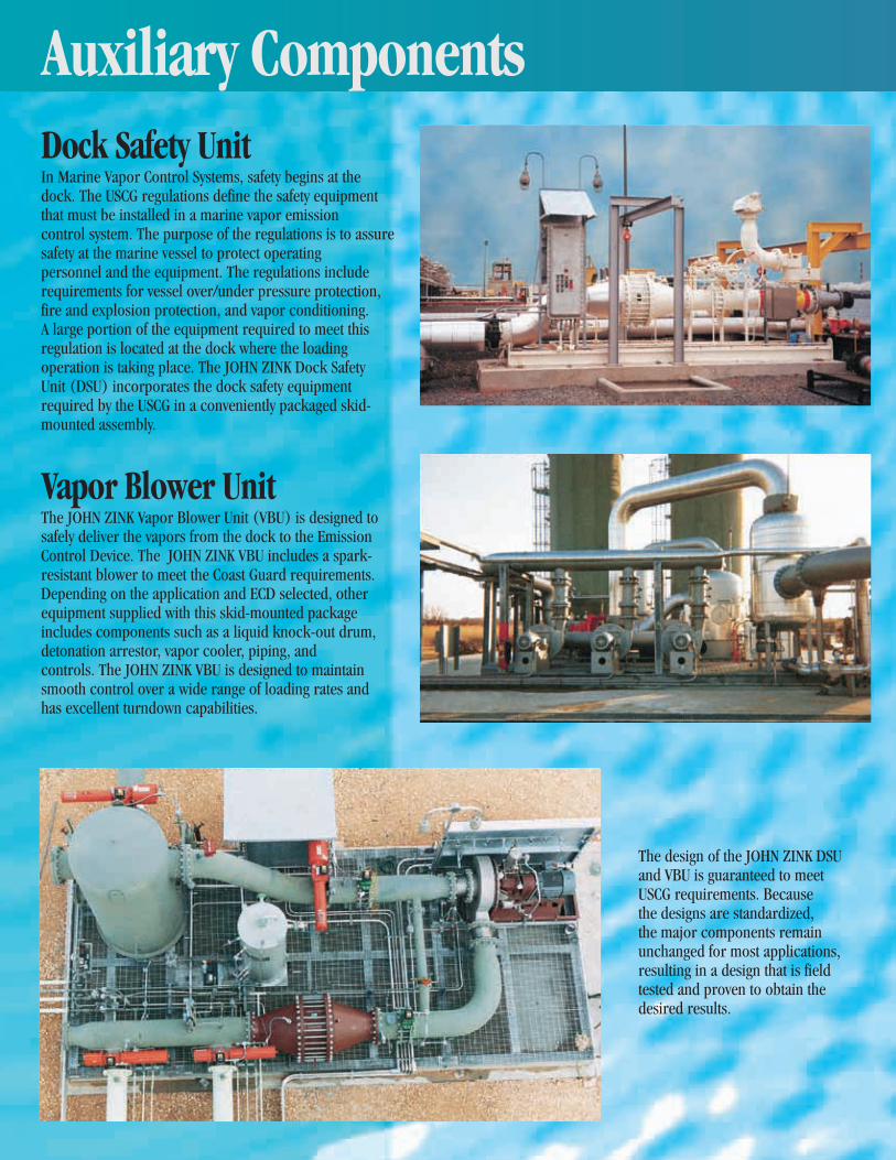
Dock Safety UnitIn Marine Vapor Control Systems, safety begins at the dock. The USCG regulations define the safety equipment that must be installed in a marine vapor emission control system. The purpose of the regulations is to assure safety at the marine vessel to protect operating personnel and the equipment. The regulations include requirements for vessel over/under pressure protection, fire and explosion protection, and vapor conditioning. A large portion of the equipment required to meet this regulation is located at the dock where the loading operation is taking place. The JohN ZINk Dock Safety Unit (DSU) incorporates the dock safety equipment required by the USCG in a conveniently packaged skid- mounted assembly.
Vapor Blower UnitThe JohN ZINk Vapor Blower Unit (VBU) is designed to safely deliver the vapors from the dock to the Emission Control Device. The JohN ZINk VBU includes a spark-resistant blower to meet the Coast Guard requirements. Depending on the application and ECD selected, other equipment supplied with this skid-mounted package includes components such as a liquid knock-out drum, detonation arrestor, vapor cooler, piping, and controls. The JohN ZINk VBU is designed to maintain smooth control over a wide range of loading rates and has excellent turndown capabilities.
Auxiliary Components
The design of the JohN ZINk DSU and VBU is guaranteed to meet USCG requirements. Because the designs are standardized, the major components remain unchanged for most applications, resulting in a design that is field tested and proven to obtain the desired results.

John Zink Vapor Control SchoolComprehensive vapor control courses held at the JOHN ZINK INSTITUTESM
help vapor control operators and engi-neers optimize their equipment and address issues at their facilities.
ServiceJohn Zink Company has a nationwide service organization devoted to servicing vapor control equipment. our service capabilities include:• Equipment startup and commissioning.
• Scheduled preventive maintenance services by trained factory technicians.
• Emergency call out services.
• Equipment rebuilding and retrofit packages.
• Compliance testing.
• Replacement parts.
• Rental equipment for temporary compliance.
For more information, please call 800-755-4252.
Trailer-mounted vertical-fired combustor ready for operation
Trailer-mounted vertical-fired combustor ready for transportation
www.johnz ink.com
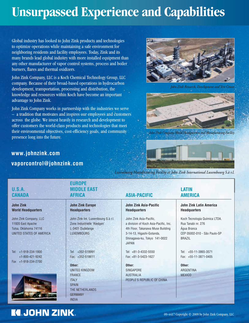
09-4417 Copyright © 2009 by John Zink Company, LLC
Luxembourg Manufacturing Facility at John Zink International Luxembourg S.à r.l.
John Zink Research, Development and Test Center
John Zink Company World Headquarters and Manufacturing Facility
Unsurpassed Experience and Capabilities
Global industry has looked to John Zink products and technologies to optimize operations while maintaining a safe environment for neighboring residents and facility employees. Today, Zink and its many brands lead global industry with more installed equipment than any other manufacturer of vapor control systems, process and boiler burners, flares and thermal oxidizers.
John Zink Company, LLC is a koch Chemical Technology Group, LLC company. Because of their broad-based operations in hydrocarbon development, transportation, processing and distribution, the knowledge and resources within koch have become an important advantage to John Zink.
John Zink Company works in partnership with the industries we serve – a tradition that motivates and inspires our employees and customers across the globe. We invest heavily in research and development to offer customers the world-class products and technologies that meet their environmental objectives, cost-efficiency goals, and community presence long into the future.
www.johnzink.com
John Zink World Headquarters
John Zink Company, LLC11920 East ApacheTulsa, Oklahoma 74116 UNITED STATES OF AMERICA
Tel: +1-918-234-1800 +1-800-421-9242Fax +1-918-234-2700
U.S.A.CANADA
John Zink EuropeHeadquarters
John Zink Int. Luxembourg S.à r.l.Zone Industrielle 'Riedgen 'L-3401 Dudelange LUXEMBOURG
Tel: +352-518991Fax: +352-518611
Other:UNITED KINGDOMFRANCEITALYSPAINTHE NETHERLANDSGERMANYINDIA
EUROPEMIDDLE EASTAFRICA
John Zink Asia-PacificHeadquarters
John Zink Asia-Pacific,a division of Koch Asia-Pacific, Inc.4th Floor, Takanawa Muse Building3-14-13, Higashi-Gotanda,Shinagawa-ku, Tokyo 141-0022JAPAN
Tel: +81-3-4332-5550Fax: +81-3-5423-1627
Other:SINGAPOREAUSTRALIAPEOPLE'S REPUBLIC OF CHINA
ASIA-PACIFIC
John Zink Latin AmericaHeadquarters
Koch Tecnologia Química LTDA.Rua Tanabi nr. 276 Água BrancaCEP 05002-010 - São Paulo-SPBRAZIL
Tel: +55-11-3865-3571Fax: +55-11-3871-0405
Other:ARGENTINAMEXICO
LATIN AMERICA

Global New Windsor Project Town of New Windsor, Orange County, New York Section 10 and Article 15 Permit Application Narrative 20
APPENDIX F
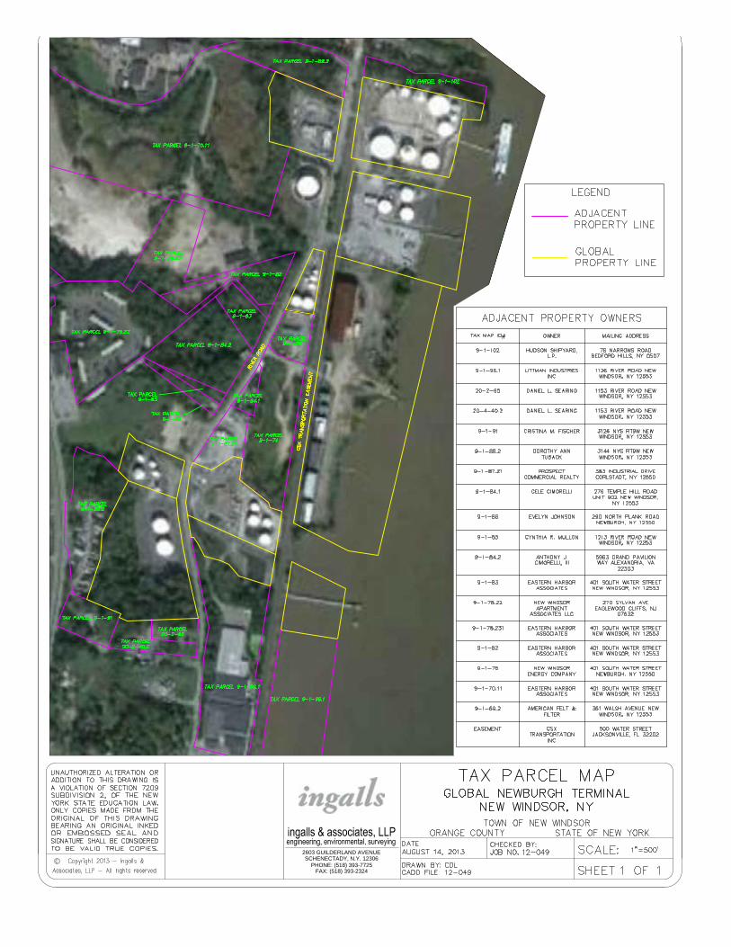
FAX: (518) 393-2324
PHONE: (518) 393-7725
SCHENECTADY, N.Y. 12306
2603 GUILDERLAND AVENUE