glk - mercedes-benz usaassets.mbusa.com/vcm/cac_rapmd/15glkoperatorsmanual.pdf · welcome to the...
TRANSCRIPT
GLKOperator's Manual
Order no. 6515 0834 13 Part no. 204 584 79 00 Edition B 2015
É2045847900fËÍ2045847900
GLK O
perat
or's M
anua
l
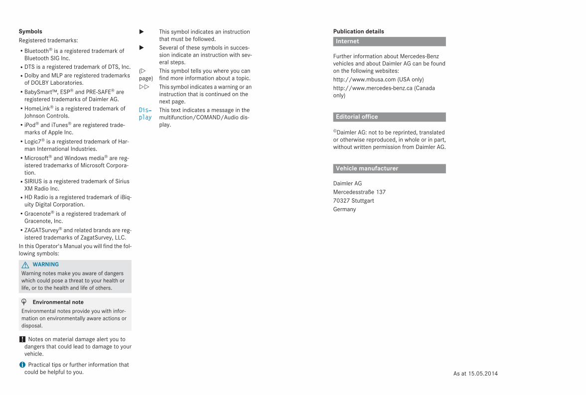
Publication detailsInternet
Further information about Mercedes-Benzvehicles and about Daimler AG can be foundon the following websites:http://www.mbusa.com (USA only)http://www.mercedes-benz.ca (Canadaonly)
Editorial office
©Daimler AG: not to be reprinted, translatedor otherwise reproduced, in whole or in part,without written permission from Daimler AG.
Vehicle manufacturer
Daimler AGMercedesstraße 13770327 StuttgartGermany
SymbolsRegistered trademarks:RBluetooth® is a registered trademark of
Bluetooth SIG Inc.RDTS is a registered trademark of DTS, Inc.RDolby and MLP are registered trademarks
of DOLBY Laboratories.RBabySmart™, ESP® and PRE-SAFE® are
registered trademarks of Daimler AG.RHomeLink® is a registered trademark of
Johnson Controls.RiPod® and iTunes® are registered trade-
marks of Apple Inc.RLogic7® is a registered trademark of Har-
man International Industries.RMicrosoft® and Windows media® are reg-
istered trademarks of Microsoft Corpora-tion.RSIRIUS is a registered trademark of Sirius
XM Radio Inc.RHD Radio is a registered trademark of iBiq-
uity Digital Corporation.RGracenote® is a registered trademark of
Gracenote, Inc.RZAGATSurvey® and related brands are reg-
istered trademarks of ZagatSurvey, LLC.In this Operator's Manual you will find the fol-lowing symbols:
G WARNINGWarning notes make you aware of dangerswhich could pose a threat to your health orlife, or to the health and life of others.
H Environmental noteEnvironmental notes provide you with infor-mation on environmentally aware actions ordisposal.
! Notes on material damage alert you todangers that could lead to damage to yourvehicle.
i Practical tips or further information thatcould be helpful to you.
X This symbol indicates an instructionthat must be followed.
X Several of these symbols in succes-sion indicate an instruction with sev-eral steps.
(Ypage)
This symbol tells you where you canfind more information about a topic.
YY This symbol indicates a warning or aninstruction that is continued on thenext page.
Dis‐play
This text indicates a message in themultifunction/COMAND/Audio dis-play.
As at 15.05.2014
Welcome to the world of Mercedes-BenzWe urge you to read this Operator's Manualcarefully and familiarize yourself with thevehicle before driving. For your own safetyand a longer vehicle life, follow the instruc-tions and warning notices in this manual.Ignoring them could result in damage to thevehicle or personal injury to you or others.Vehicle damage caused by failure to followinstructions is not covered by the Mercedes-Benz Limited Warranty.The equipment or product designation of yourvehicle may vary depending on:RmodelRorderRcountry specificationRavailabilityMercedes-Benz therefore reserves the rightto introduce changes in the following areas:RdesignRequipmentRtechnical featuresThe equipment in your vehicle may thereforediffer from that shown in the descriptions andillustrations.The following are integral components of thevehicle:ROperator's ManualRMaintenance BookletREquipment-dependent supplementsKeep these documents in the vehicle at alltimes. If you sell the vehicle, always pass alldocuments on to the new owner.The technical documentation team atDaimler AG wishes you safe and pleasantmotoring.Mercedes-Benz USA, LLCMercedes-Benz Canada, Inc.A Daimler Company
2045847900 É2045847900fËÍ

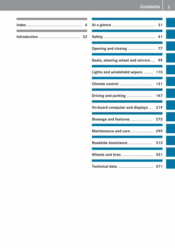
Index ....................................................... 4
Introduction ......................................... 22
At a glance ........................................... 31
Safety ................................................... 41
Opening and closing ........................... 77
Seats, steering wheel and mirrors .... 99
Lights and windshield wipers .......... 115
Climate control ................................. 131
Driving and parking .......................... 147
On-board computer and displays .... 219
Stowage and features ...................... 273
Maintenance and care ...................... 299
Roadside Assistance ........................ 313
Wheels and tires ............................... 331
Technical data ................................... 371
Contents 3

1, 2, 3 ...4ETS
see ETS/4ETS (Electronic Trac-tion System)
4MATIC (permanent four-wheeldrive) .................................................. 18512 V socket
see Sockets115 V socket ...................................... 285360° camera
Function/notes ............................. 198
AABS (Anti-lock Braking System)
Display message ............................ 236Function/notes ................................ 68Important safety notes .................... 68Warning lamp ................................. 262
Activating/deactivating coolingwith air dehumidification ................. 137Active Blind Spot Assist
Activating/deactivating (on-board computer) ............................ 229Display message ............................ 252Function/information .................... 207Trailer towing ................................. 209
Active Driving Assistance package .. 207Active Lane Keeping Assist
Activating/deactivating (on-board computer) ............................ 230Display message ............................ 251Function/information .................... 210Trailer towing ......................... 206, 212
Active light function ......................... 119Active Parking Assist
Canceling ....................................... 193Detecting parking spaces .............. 190Display message ............................ 252Exiting a parking space .................. 192Important safety notes .................. 189Parking .......................................... 191Towing a trailer .............................. 193
Adaptive Highbeam AssistFunction/notes ............................. 120Switching on/off ................... 120, 121
Additives (engine oil) ........................ 377
Air bagOccupant Classification System(OCS) ............................................... 49
Air bagsDisplay message ............................ 242Front air bag (driver, frontpassenger) ....................................... 46Important safety notes .................... 44Knee bag .......................................... 47PASSENGER AIR BAG OFF indica-tor lamp ........................................... 49Pelvis air bag ................................... 48Safety guidelines ............................. 43Side impact air bag .......................... 47Window curtain air bag .................... 49
Air filter (display message) .............. 249AIR FLOW ........................................... 139Air vents
Glove box ....................................... 144Important safety notes .................. 144Rear ............................................... 145Setting ........................................... 144Setting the center air vents ........... 144Setting the side air vents ............... 144
Air-conditioning systemsee Climate control
AlarmATA (Anti-Theft Alarm system) ......... 75Switching off (ATA) .......................... 75Switching the function on/off(ATA) ................................................ 75
Alarm systemsee ATA (Anti-Theft Alarm system)
Animals in the vehicle ......................... 67Anti-lock braking system
see ABS (Anti-lock Braking System)Anti-Theft Alarm system
see ATA (Anti-Theft Alarm system)Ashtray ............................................... 283Assistance display (on-board com-puter) .................................................. 229Assistance menu (on-board com-puter) .................................................. 228ASSYST PLUS
Displaying a service message ........ 305Hiding a service message .............. 304Notes ..................................... 304, 305
4 Index
Resetting the service interval dis-play ................................................ 305Service message ............................ 304Special service requirements ......... 305
ATA (Anti-Theft Alarm system)Activating/deactivating ................... 75Function ........................................... 75Switching off the alarm .................... 75
ATTENTION ASSISTActivating/deactivating ................. 229Display message ............................ 250Function/notes ............................. 202
Audio menu (on-board com-puter) .................................................. 226Audio system
see separate operating instructionsAuthorized Mercedes-Benz Center
see Qualified specialist workshopAuthorized workshop
see Qualified specialist workshopAUTO lights
Display message ............................ 246see Lights
Automatic car wash (care) ............... 306Automatic engine start (ECO start/stop function) .................................... 153Automatic engine switch-off (ECOstart/stop function) .......................... 153Automatic headlamp mode .............. 116Automatic transmission
Accelerator pedal position ............. 159Automatic drive program ............... 160Changing gear ............................... 159DIRECT SELECT lever ..................... 156Display message ............................ 257Driving tips .................................... 159Emergency running mode .............. 162Engaging drive position .................. 158Engaging neutral ............................ 157Engaging park position automati-cally ............................................... 157Engaging reverse gear ................... 157Engaging the park position ............ 157Kickdown ....................................... 159Manual drive program .................... 160Overview ........................................ 156Problem (malfunction) ................... 162
Program selector button ................ 159Pulling away ................................... 152Starting the engine ........................ 151Steering wheel paddle shifters ...... 160Trailer towing ................................. 159Transmission position display ........ 157Transmission positions .................. 158
Automatic transmission emer-gency mode ....................................... 162
BBackup lamp
Changing bulbs .............................. 125Display message ............................ 245
Bag hook ............................................ 278Ball coupling
Installing ........................................ 214Removing ....................................... 217Storing ........................................... 217
BAS (Brake Assist System) ................. 69BAS PLUS (Brake Assist SystemPLUS) .................................................... 69Battery (SmartKey)
Checking .......................................... 81Important safety notes .................... 81Replacing ......................................... 81
Battery (vehicle)Charging ........................................ 321Display message ............................ 248Important safety notes .................. 319Jump starting ................................. 323
Beltsee Seat belts
Belt force limiterActivation ......................................... 60Function ........................................... 60
Blind Spot AssistActivating/deactivating ................. 229Display message ............................ 252Notes/function .............................. 203Trailer towing ................................. 205see Active Blind Spot Assist
BlueTEC (DEF) .................................... 376BlueTEC®
Adding DEF .................................... 165Brake Assist
see BAS (Brake Assist System)
Index 5
Brake fluidDisplay message ............................ 238Notes ............................................. 377
Brake lampsDisplay message ............................ 244
BrakesABS .................................................. 68BAS .................................................. 69BAS PLUS ........................................ 69Brake fluid (notes) ......................... 377Display message ............................ 236Important safety notes .................. 172Maintenance .................................. 172Parking brake ........................ 169, 173Riding tips ...................................... 172Warning lamp ................................. 262
Breakdownsee Flat tiresee Towing away/tow-starting
Brightness control knob (instru-ment cluster lighting, multifunc-tion steering wheel with 12 but-tons) ..................................................... 33Bulbs
see Replacing bulbs
CCalifornia
Important notice for retail cus-tomers and lessees .......................... 24
Calling up a malfunctionsee Display messages
Carsee Vehicle
CareCar wash ........................................ 306Carpets .......................................... 312Display ........................................... 310Exterior lights ................................ 309Gear or selector lever .................... 311Interior ........................................... 310Matte finish ................................... 308Notes ............................................. 305Paint .............................................. 307Plastic trim .................................... 310Power washer ................................ 306Rear view camera .......................... 309
Roof lining ...................................... 312Seat belt ........................................ 312Seat cover ..................................... 311Sensors ......................................... 309Steering wheel ............................... 311Tail pipes ....................................... 309Trim pieces .................................... 311Washing by hand ........................... 306Wheels ........................................... 307Windows ........................................ 308Wiper blades .................................. 308Wooden trim .................................. 311
Cargo compartment coverImportant safety notes .................. 278
Cargo compartment enlarge-ment ................................................... 276Cargo compartment floor
Opening/closing ............................ 281Stowage well (under) ..................... 281
Cargo netAttaching ....................................... 280Important safety information ......... 279
Cargo tie down rings ......................... 277CD player/CD changer (on-boardcomputer) .......................................... 226Center console
Lower section .................................. 37Upper section .................................. 36
Central lockingAutomatic locking (on-board com-puter) ............................................. 232Locking/unlocking (SmartKey) ........ 78
Changing bulbsCornering light function ................. 124High-beam headlamps ................... 124Low-beam headlamps .................... 124Parking lamps ................................ 124Reversing lamps ............................ 125Standing lamps (front) ................... 124Turn signals (front) ......................... 124
Child seatLATCH-type (ISOFIX) child seatanchors ............................................ 64Top Tether ....................................... 65
Child-proof locksImportant safety notes .................... 66Rear doors ....................................... 67
6 Index
ChildrenRestraint systems ............................ 61Special seat belt retractor ............... 64
Cigarette lighter ................................ 284Cleaning
Mirror turn signal ........................... 309Trailer tow hitch ............................. 310
Climate controlAutomatic climate control (3-zone) .............................................. 136Controlling automatically ............... 139Cooling with air dehumidification .. 137Defrosting the windows ................. 142Defrosting the windshield .............. 141Dual-zone automatic climate con-trol ................................................. 133Important safety notes .................. 132Indicator lamp ................................ 139Information about using auto-matic climate control ..................... 137Information about using dual-zoneautomatic climate control .............. 134Maximum cooling .......................... 142Overview of systems ...................... 132Problem with the rear windowdefroster ........................................ 143Problems with cooling with airdehumidification ............................ 139Rear control panel ......................... 136Refrigerant ..................................... 379Refrigerant filling capacity ............. 380Setting the air distribution ............. 140Setting the air vents ...................... 144Setting the airflow ......................... 141Setting the climate mode (AIRFLOW) ............................................ 139Setting the temperature ................ 140Switching air-recirculation modeon/off ............................................ 143Switching on/off ........................... 137Switching residual heat on/off ...... 143Switching the rear windowdefroster on/off ............................ 142Switching the ZONE function on/off .................................................. 141
Coat hooks ......................................... 280Cockpit
Overview .......................................... 32
see Instrument clusterCollapsible spare wheel
Inflating ......................................... 367see Emergency spare wheel
COMANDsee separate operating instructions
Combination switch .......................... 118Consumption statistics (on-boardcomputer) .......................................... 223Convenience closing feature .............. 93Convenience opening feature ............ 93Coolant (engine)
Checking the level ......................... 303Display message ............................ 246Filling capacity ............................... 379Important safety notes .................. 378Temperature gauge ........................ 220Warning lamp ................................. 268
Coolingsee Climate control
Copyright ............................................. 29Cornering light function
Changing bulbs .............................. 124Display message ............................ 243Function/notes ............................. 120
Crash-responsive emergency light-ing ....................................................... 122Cruise control
Cruise control lever ....................... 175Deactivating ................................... 176Display message ............................ 254Driving system ............................... 175Function/notes ............................. 175Important safety notes .................. 175Setting a speed .............................. 176Storing and maintaining currentspeed ............................................. 175
Cup holderCenter console .............................. 282Important safety notes .................. 282Rear compartment ......................... 282
Customer Assistance Center(CAC) ..................................................... 27Customer Relations Department ....... 27
Index 7
DDashboard
see Instrument clusterData
see Technical dataDaytime running lamps
Display message ............................ 246Switching on/off (on-board com-puter) ............................................. 231Switching on/off (switch) .............. 116
Declarations of conformity ................. 26DEF
Adding ........................................... 165Display message ............................ 249Filling capacity ............................... 376Important safety notes .................. 376
Delayed switch-offExterior lighting (on-board com-puter) ............................................. 231Interior lighting .............................. 232
Diagnostics connection ...................... 26Diesel .................................................. 375Digital speedometer ......................... 224DIRECT SELECT lever
Automatic transmission ................. 156Display (cleaning instructions) ........ 310Display messages
ASSYST PLUS ................................ 304Calling up (on-board computer) ..... 235Driving systems ............................. 250Engine ............................................ 246General notes ................................ 235Hiding (on-board computer) ........... 235KEYLESS-GO .................................. 258Lights ............................................. 243Safety systems .............................. 236SmartKey ....................................... 258Tires ............................................... 255Vehicle ........................................... 257
Distance recorder ............................. 223see Odometersee Trip odometer
Distance warning (warning lamp) .... 270DISTRONIC PLUS
Activation conditions ..................... 178Deactivating ................................... 182Display message ............................ 253
Displays in the multifunction dis-play ................................................ 181Driving tips .................................... 182Function/notes ............................. 176Important safety notes .................. 176Setting the specified minimumdistance ......................................... 180Warning lamp ................................. 270
DoorsAutomatic locking (on-board com-puter) ............................................. 232Automatic locking (switch) ............... 86Central locking/unlocking(SmartKey) ....................................... 78Control panel ................................... 39Display message ............................ 257Emergency locking ........................... 86Emergency unlocking ....................... 86Important safety notes .................... 84Opening (from inside) ...................... 84
Drinking and driving ......................... 170Drive program
Automatic ...................................... 160Display ........................................... 157Display (DIRECT SELECT lever) ...... 157Manual ........................................... 160
Driver's doorsee Doors
Driving abroadMercedes-Benz Service ................. 305
Driving lampssee Daytime running lamps
Driving safety systemsABS (Anti-lock Braking System) ....... 68BAS (Brake Assist System) .............. 69BAS PLUS (Brake Assist SystemPLUS) ............................................... 69EBD (electronic brake force distri-bution) ............................................. 73ESP® (Electronic Stability Pro-gram) ............................................... 70ETS/4ETS (Electronic TractionSystem) ........................................... 70Important safety information ........... 68Overview .......................................... 68PRE-SAFE® Brake ............................. 73
8 Index

Driving systems360°camera .................................. 198Active Blind Spot Assist ................. 207Active Driving Assistance pack-age ................................................. 207Active Lane Keeping Assist ............ 210Active Parking Assist ..................... 189ATTENTION ASSIST ........................ 202Blind Spot Assist ............................ 203Cruise control ................................ 175Display message ............................ 250DISTRONIC PLUS ........................... 176HOLD function ............................... 184Lane Keeping Assist ...................... 205Lane Tracking package .................. 203PARKTRONIC ................................. 186Rear view camera .......................... 193
Driving tipsAutomatic transmission ................. 159Brakes ........................................... 172Break-in period .............................. 148DISTRONIC PLUS ........................... 182Downhill gradient ........................... 172Drinking and driving ....................... 170Driving in winter ............................. 174Driving on flooded roads ................ 174Driving on wet roads ...................... 173Exhaust check ............................... 170Fuel ................................................ 170General .......................................... 169Hydroplaning ................................. 173Icy road surfaces ........................... 174Limited braking efficiency on sal-ted roads ....................................... 172Snow chains .................................. 335Towing a trailer .............................. 212Wet road surface ........................... 172
DVD video (on-board computer) ...... 227
EEASY-ENTRY feature
Activating/deactivating ................. 233Function/notes ............................. 108
EASY-EXIT featureCrash-responsive ........................... 109Function/notes ............................. 108Switching on/off ........................... 233
EBD (electronic brake force distri-bution)
Display message ............................ 237Function/notes ................................ 73
ECO displayFunction/notes ............................. 170On-board computer ....................... 224
ECO start/stop functionAutomatic engine start .................. 153Automatic engine switch-off .......... 153Deactivating/activating ................. 154General information ....................... 153Important safety notes .................. 153Introduction ................................... 152
Electronic Stability Programsee ESP® (Electronic Stability Program)
Emergency releaseDriver's door .................................... 86Vehicle ............................................. 86
Emergency spare wheelGeneral notes ................................ 366Important safety notes .................. 366Storage location ............................ 366Stowing .......................................... 367Technical data ............................... 369
Emergency Tensioning DevicesFunction ........................................... 60Safety guidelines ............................. 43
Emergency unlockingTailgate ............................................ 91
Emissions controlService and warranty information .... 23
EngineCheck Engine warning lamp ........... 267Display message ............................ 246ECO start/stop function ................ 152Engine number ............................... 373Irregular running ............................ 155Jump-starting ................................. 323Starting problems .......................... 155Starting the engine with theSmartKey ....................................... 151Starting with KEYLESS-GO ............. 151Switching off .................................. 168Tow-starting (vehicle) ..................... 328
Engine electronicsProblem (malfunction) ................... 155
Index 9
Engine jump startingsee Jump starting (engine)
Engine oilAdding ........................................... 302Additives ........................................ 377Checking the oil level ..................... 301Checking the oil level using thedipstick .......................................... 301Display message ............................ 248Filling capacity ............................... 377Notes about oil grades ................... 377Notes on oil level/consumption .... 301Viscosity ........................................ 377
ESP® (Electronic Stability Pro-gram)
Deactivating/activating ................... 71Display message ............................ 236ETS/4ETS ........................................ 70Function/notes ................................ 70General notes .................................. 70Important safety information ........... 71Trailer stabilization ........................... 72Warning lamp ................................. 264
ETS/4ETS (Electronic Traction Sys-tem) ...................................................... 70Exhaust check ................................... 170Exhaust tail pipe (cleaning instruc-tions) .................................................. 309Exterior lighting
Setting options .............................. 116see Lights
Exterior mirrorsAdjusting ....................................... 109Dipping (automatic) ....................... 110Folding in when locking (on-boardcomputer) ...................................... 233Folding in/out (automatically) ....... 110Folding in/out (electrically) ........... 110Out of position (troubleshooting) ... 110Setting ........................................... 110Storing settings (memory func-tion) ............................................... 112Storing the parking position .......... 111
FFiller cap
see Fuel filler flap
Flat tireMOExtended tires .......................... 315Preparing the vehicle ..................... 314TIREFIT kit ...................................... 316see Emergency spare wheel
Floormats ........................................... 298Fog lamps
Switching on/off ........................... 117Folding the rear bench seat for-wards/back ....................................... 276Fording
On flooded roads ........................... 174Front fog lamps
Switching on/off ........................... 117Fuel
Additives ........................................ 375Consumption statistics .................. 223Displaying the current consump-tion ................................................ 224Displaying the range ...................... 224Driving tips .................................... 170Fuel gauge ....................................... 33Grade (gasoline) ............................ 374Important safety notes .................. 373Premium-grade unleaded gaso-line ................................................. 374Problem (malfunction) ................... 165Quality (diesel) ............................... 375Refueling ........................................ 162Tank content/reserve fuel ............. 374
Fuel filler flapOpening ......................................... 164
Fuel filter (display message) ............ 249Fuel level
Calling up the range (on-boardcomputer) ...................................... 224
Fuel tankCapacity ........................................ 374Problem (malfunction) ................... 165
Fuse allocation chart (vehicle toolkit) ...................................................... 314Fuses
Allocation chart ............................. 328Before changing ............................. 328Dashboard fuse box ....................... 328Fuse box in the cargo compart-ment .............................................. 329
10 Index
Fuse box in the engine compart-ment .............................................. 329Important safety notes .................. 328
GGarage door opener
Clearing the memory ..................... 298General notes ................................ 295Important safety notes .................. 295Opening/closing the garage door .. 297Programming (button in the rear-view mirror) ................................... 295Synchronizing the rolling code ....... 296
Gear or selector lever (cleaningguidelines) ......................................... 311Genuine parts ...................................... 22Glove box ........................................... 275GTW (Gross Trailer Weight) (defini-tion) .................................................... 353
HHazard warning lamps ...................... 119Head restraints
Adjusting ....................................... 102Adjusting (electrically) ................... 103Adjusting (manually) ...................... 103Adjusting (rear) .............................. 103Installing/removing (rear) .............. 104Luxury ............................................ 103see NECK-PRO head restraints/NECK-PRO luxury head restraints
HeadlampsAdding fluid to cleaning system ..... 303Cleaning system (function) ............ 119Cleaning system (notes) ................ 379Fogging up ..................................... 121see Automatic headlamp mode
Heatingsee Climate control
High-beam headlampsChanging bulbs .............................. 124Display message ............................ 245Switching on/off ........................... 118
Hill start assist .................................. 152HOLD function
Deactivating ................................... 185
Display message ............................ 250Function/notes ............................. 184
HoodClosing ........................................... 301Display message ............................ 257Important safety notes .................. 300Opening ......................................... 300
Horn ...................................................... 32Hydroplaning ..................................... 173
IIgnition lock
see Key positionsImmobilizer .......................................... 74Indicator lamps
see Warning and indicator lampsIndicators
see Turn signalsInstrument cluster
Overview .......................................... 33Settings ......................................... 230Warning and indicator lamps ........... 34
Instrument cluster lighting .............. 231Interior lighting ................................. 121
Automatic control .......................... 122Delayed switch-off (on-boardcomputer) ...................................... 232Emergency lighting ........................ 122Manual control ............................... 122Overview ........................................ 121Reading lamp ................................. 121Setting the brightness of the dis-play/switch (on-board computer) .. 231
JJack
Storage location ............................ 314Using ............................................. 357
Jump starting (engine) ...................... 323
KKey positions
KEYLESS-GO .................................. 149SmartKey ....................................... 149
KEYLESS-GOConvenience closing feature ............ 94
Index 11
Display message ............................ 258Locking ............................................ 79Start/Stop button .......................... 149Starting the engine ........................ 151Unlocking ......................................... 79
KickdownDriving tips .................................... 159
Knee bag .............................................. 47
LLamps
see Warning and indicator lampsLane Keeping Assist
Activating/deactivating ................. 230Display message ............................ 251Function/information .................... 205
Lane Tracking package ..................... 203LATCH-type (ISOFIX) child seatanchors ................................................ 64License plate lamp (display mes-sage) ................................................... 245Light function, active
Display message ............................ 246Light sensor (display message) ....... 246Lights
Activating/deactivating the inte-rior lighting delayed switch-off ....... 232Active light function ....................... 119Automatic headlamp mode ............ 116Cornering light function ................. 120Display message ............................ 243Fog lamps ...................................... 117Hazard warning lamps ................... 119High beam flasher .......................... 119High-beam headlamps ................... 118Light switch ................................... 116Low-beam headlamps .................... 117Parking lamps ................................ 118Rear fog lamp ................................ 118Setting the brightness of the dis-play/switch (on-board computer) .. 231Standing lamps .............................. 118Switching the daytime runninglamps on/off (on-board com-puter) ............................................. 231Switching the daytime runninglamps on/off (switch) .................... 116
Switching the exterior lightingdelayed switch-off on/off (on-board computer) ............................ 231Switching the surround lightingon/off (on-board computer) .......... 231Turn signals ................................... 118see Interior lightingsee Replacing bulbs
Loading guidelines ............................ 274Locking
see Central lockingLocking (doors)
Automatic ........................................ 86Emergency locking ........................... 86From inside (central locking but-ton) .................................................. 85
Locking centrallysee Central locking
Locking verification signal (on-board computer) ............................... 232Low-beam headlamps
Changing bulbs .............................. 124Display message ............................ 243Switching on/off ........................... 117
Lumbar supportAdjusting ....................................... 104Adjusting the 4-way lumbar sup-port ................................................ 104
Luxury head restraints ..................... 103
MM+S tires ............................................ 335Malfunction message
see Display messagesMatte finish (cleaning instruc-tions) .................................................. 308mbrace
Call priority .................................... 291Display message ............................ 238Downloading destinations(COMAND) ..................................... 291Downloading routes ....................... 294Emergency call .............................. 288General notes ................................ 287Geo fencing ................................... 294Locating a stolen vehicle ............... 293MB info call button ........................ 290
12 Index
Remote fault diagnosis .................. 293Remote vehicle locking .................. 292Roadside Assistance button .......... 289Search & Send ............................... 292Self-test ......................................... 288Speed alert .................................... 294System .......................................... 288Triggering the vehicle alarm ........... 295Vehicle remote unlocking .............. 292
Mechanical keyFunction/notes ................................ 80Locking vehicle ................................ 86Unlocking the driver's door .............. 86
Media Interfacesee Separate operating instructions
Memory card (audio) ......................... 226Memory function ............................... 112Message memory (on-board com-puter) .................................................. 235Messages
see Display messagesMirrors
see Exterior mirrorssee Rear-view mirrorsee Vanity mirror (in the sun visor)
Mobile phoneMenu (on-board computer) ............ 227
Modifying the programming(SmartKey) ........................................... 80MOExtended tires .............................. 315Mounting wheels
Lowering the vehicle ...................... 359Mounting a new wheel ................... 358Preparing the vehicle ..................... 356Raising the vehicle ......................... 357Removing a wheel .......................... 358Securing the vehicle against roll-ing away ........................................ 356
MP3Operation ....................................... 226see separate operating instructions
Multifunction displayFunction/notes ............................. 222Permanent display ......................... 231
Multifunction steering wheelOperating the on-board computer .. 221Overview .......................................... 35
NNavigation
Menu (on-board computer) ............ 225see separate operating instructions
NECK-PRO head restraintsOperation ......................................... 54Resetting triggered .......................... 55
NECK-PRO luxury head restraintsOperation ......................................... 54Resetting when triggered ................. 55
Notes on breaking-in a new vehi-cle ....................................................... 148
OOccupant Classification System(OCS)
Faults ............................................... 53Operation ......................................... 49System self-test ............................... 52
Occupant safetyAir bags ........................................... 44Children in the vehicle ..................... 61Occupant Classification System(OCS) ............................................... 49Pets in the vehicle ........................... 67PRE-SAFE® (anticipatory occu-pant protection) ............................... 54SRS (Supplemental Restraint Sys-tem) ................................................. 43System overview .............................. 42
OCSFaults ............................................... 53Operation ......................................... 49System self-test ............................... 52
Odometer ........................................... 223Off-road system
4MATIC .......................................... 185Oil
see Engine oilOn-board computer
Assistance menu ........................... 228Audio menu ................................... 226Convenience submenu .................. 233Display messages .......................... 235Displaying a service message ........ 305Factory settings submenu ............. 234
Index 13
Important safety notes .................. 220Instrument cluster submenu .......... 230Lighting submenu .......................... 231Menu overview .............................. 223Message memory .......................... 235Navigation menu ............................ 225Operation ....................................... 221Service menu ................................. 230Settings menu ............................... 230Standard display ............................ 223Telephone menu ............................ 227Trip menu ...................................... 223Vehicle submenu ........................... 232Video DVD operation ..................... 227
Opening and closing the side trimpanels ................................................. 125Operating safety
Declaration of conformity ................ 26Important safety notes .................... 25
Operating systemsee On-board computer
Operator's ManualVehicle equipment ........................... 23
Outside temperature display ........... 221Overhead control panel ...................... 38Override feature
Rear side windows ........................... 67
PPaint code number ............................ 372Paintwork (cleaning instructions) ... 307Panic alarm .......................................... 42Panorama roof with power tilt/sliding panel
Important safety notes .................... 95Opening/closing .............................. 96Opening/closing the roller sun-blind ................................................. 97Problem (malfunction) ..................... 97Resetting ......................................... 97
Parking ............................................... 168Important safety notes .................. 168Parking brake ................................ 169Position of exterior mirror, front-passenger side ............................... 111Rear view camera .......................... 193see PARKTRONIC
Parking aidActive Parking Assist ..................... 189see Exterior mirrorssee PARKTRONIC
Parking assistancesee PARKTRONIC
Parking brakeDisplay message ............................ 237Notes/function .............................. 169
Parking lampsChanging bulbs .............................. 124Switching on/off ........................... 118
PARKTRONICDeactivating/activating ................. 188Driving system ............................... 186Function/notes ............................. 186Important safety notes .................. 186Problem (malfunction) ................... 189Range of the sensors ..................... 186Trailer towing ................................. 188Warning display ............................. 187
PASSENGER AIR BAGDisplay message ............................ 242
PASSENGER AIR BAG OFFProblem (malfunction) ..................... 53
PASSENGER AIR BAG OFF indicatorlamp ...................................................... 49PASSENGER AIRBAG
Problems (malfunction) .................. 242Pets in the vehicle ............................... 67Plastic trim (cleaning instruc-tions) .................................................. 310Power washers .................................. 306Power windows
see Side windowsPRE-SAFE® (anticipatory occupantprotection)
Display message ............................ 238Operation ......................................... 54
PRE-SAFE® BrakeActivating/deactivating ................. 229Display message ............................ 239Function/notes ................................ 73Warning lamp ................................. 270
Program selector button .................. 159Protection against theft
ATA (Anti-Theft Alarm system) ......... 75
14 Index
Immobilizer ...................................... 74Protection of the environment
General notes .................................. 22Pulling away
Automatic transmission ................. 152
QQR code
Mercedes-Benz Guide App ................. 1Rescue card ..................................... 28
Qualified specialist workshop ........... 27
RRadar sensor system
Activating/deactivating ................. 233Display message ............................ 250
RadioSelecting a station ......................... 226see separate operating instructions
Radio-wave reception/transmis-sion in the vehicle
Declaration of conformity ................ 26Reading lamp ..................................... 121Rear compartment
Setting the air vents ...................... 145Setting the airflow ......................... 141
Rear fog lampDisplay message ............................ 245Switching on/off ........................... 118
Rear view cameraCleaning instructions ..................... 309Function/notes ............................. 193Switching on/off ........................... 194
Rear window defrosterProblem (malfunction) ................... 143Switching on/off ........................... 142
Rear window wiperReplacing the wiper blade .............. 128Switching on/off ........................... 127
Rear-view mirrorAnti-glare (manual) ........................ 109Dipping (automatic) ....................... 110
Refrigerant (air-conditioning sys-tem)
Important safety notes .................. 379Refueling
Fuel gauge ....................................... 33
Important safety notes .................. 162Refueling process .......................... 163see Fuel
Remote controlGarage door opener ....................... 295Programming (garage dooropener) .......................................... 295
Replacing bulbsImportant safety notes .................. 122Overview of bulb types .................. 123
Reporting safety defects .................... 27Rescue card ......................................... 28Reserve (fuel tank)
see FuelReserve fuel
Display message ............................ 248Warning lamp ................................. 267see Fuel
Residual heat (climate control) ........ 143Reversing feature
Panorama sliding sunroof ................ 95Roller sunblinds ............................... 96Side windows ................................... 92Tailgate ............................................ 87
Roadside Assistance (breakdown) .... 24Roller blind
see Roller sunblindRoller sunblind
Opening/closing .............................. 97Panorama roof with power tilt/sliding panel ..................................... 96
Roof carrier ........................................ 281Roof lining and carpets (cleaningguidelines) ......................................... 312Roof load (maximum) ........................ 380Route (navigation)
see Route guidance (navigation)Route guidance (navigation) ............ 225
SSafety
Child restraint systems .................... 61Children in the vehicle ..................... 61Occupant Classification System(OCS) ............................................... 49Overview of occupant safety sys-tems ................................................ 42
Index 15
Safety systemsee Driving safety systems
Seat beltsAdjusting the driver's and front-passenger seat belt ......................... 59Adjusting the height ......................... 59Belt force limiters ............................ 60center rear-compartment seat ......... 59Cleaning ......................................... 312Correct usage .................................. 57Emergency Tensioning Devices ........ 60Fastening ......................................... 58Important safety guidelines ............. 56Releasing ......................................... 59Safety guidelines ............................. 43Switching belt adjustment on/off(on-board computer) ...................... 233Warning lamp ................................. 260Warning lamp (function) ................... 60
SeatsAdjusting (electrically) ................... 101Adjusting lumbar support .............. 104Adjusting the 4-way lumbar sup-port ................................................ 104Adjusting the head restraint .......... 102Cleaning the cover ......................... 311Correct driver's seat position ........ 100Folding the backrest (rear com-partment) forwards/back .............. 276Folding the rear bench seat for-wards/back ................................... 276Important safety notes .................. 101Seat heating problem .................... 106Storing settings (memory func-tion) ............................................... 112Switching seat heating on/off ....... 105
Sensors (cleaning instructions) ....... 309Service menu (on-board com-puter) .................................................. 230Service products
Brake fluid ..................................... 377Coolant (engine) ............................ 378DEF special additives ..................... 376Engine oil ....................................... 377Fuel ................................................ 373Important safety notes .................. 373Refrigerant (air-conditioning sys-tem) ............................................... 379
Washer fluid ................................... 379Setting the air distribution ............... 140Setting the airflow ............................ 141Settings
Factory (on-board computer) ......... 234On-board computer ....................... 230
Side impact air bag ............................. 47Side marker lamp (display mes-sage) ................................................... 245Side windows
Cleaning ......................................... 308Convenience closing feature ............ 93Convenience opening feature .......... 93Important safety information ........... 91Opening/closing .............................. 92Problem (malfunction) ..................... 94Resetting ......................................... 94
Sliding sunroofsee Panorama roof with powertilt/sliding panel
SmartKeyChanging the battery ....................... 81Changing the programming ............. 80Checking the battery ....................... 81Convenience closing feature ............ 93Convenience opening feature .......... 93Display message ............................ 258Door central locking/unlocking ....... 78Important safety notes .................... 78Loss ................................................. 83Mechanical key ................................ 80Positions (ignition lock) ................. 149Problem (malfunction) ..................... 83Starting the engine ........................ 151
Snow chains ...................................... 335Sockets
Center console .............................. 285General notes ................................ 284Rear compartment ......................... 285
Special seat belt retractor .................. 64Specialist workshop ............................ 27Speed, controlling
see Cruise controlSpeedometer
Digital ............................................ 224In the Instrument cluster ................. 33Segments ...................................... 221
16 Index
Selecting the unit of measure-ment .............................................. 230see Instrument cluster
SRS (Supplemental Restraint Sys-tem)
Display message ............................ 239Introduction ..................................... 43Warning lamp ................................. 266Warning lamp (function) ................... 43
Standing lampsChanging bulbs .............................. 124Display message ............................ 245Switching on/off ........................... 118
Start/stop functionsee ECO start/stop function
Starting (engine) ................................ 151Steering (display message) .............. 258Steering wheel
Adjusting (electrically) ................... 107Adjusting (manually) ...................... 106Button overview ............................... 35Buttons (on-board computer) ......... 221Cleaning ......................................... 311Important safety notes .................. 106Paddle shifters ............................... 160Steering wheel heating .................. 107Storing settings (memory func-tion) ............................................... 112
Steering wheel heatingProblem (malfunction) ................... 108Switching on/off ........................... 107
Steering wheel paddle shifters ........ 160Stowage areas ................................... 275Stowage compartments
Armrest (under) ............................. 275Cup holders ................................... 282Glove box ....................................... 275Important safety information ......... 275Rear ............................................... 276Stowage net ................................... 276
Stowage net ....................................... 276Summer tires ..................................... 334Sun visor ............................................ 283Surround lighting (on-board com-puter) .................................................. 231SUV
(Sport Utility Vehicle) ....................... 25
Switching air-recirculation modeon/off ................................................. 143
TTachometer ........................................ 220Tail lamps
Display message ............................ 244Tailgate
Display message ............................ 257Emergency unlocking ....................... 91Important safety notes .................... 87Limiting the opening angle ............... 90Opening dimensions ...................... 380Opening/closing (automaticallyfrom inside) ...................................... 90Opening/closing (automaticallyfrom outside) ................................... 88Opening/closing (from outside) ....... 88
Tanksee Fuel tank
Tank contentFuel gauge ....................................... 33
Technical dataCapacities ...................................... 373Emergency spare wheel ................. 369Information .................................... 372Tires/wheels ................................. 360Trailer loads ................................... 381Vehicle data ................................... 380
TELEAIDCall priority .................................... 291Downloading destinations(COMAND) ..................................... 291Downloading routes ....................... 294Emergency call .............................. 288General notes ................................ 287Geo fencing ................................... 294Locating a stolen vehicle ............... 293MB info call button ........................ 290Remote vehicle locking .................. 292Roadside Assistance button .......... 289Search & Send ............................... 292Self-test ......................................... 288Speed alert .................................... 294System .......................................... 288Triggering the vehicle alarm ........... 295Vehicle Health Check .................... 293
Index 17

Vehicle remote unlocking .............. 292Telephone
Accepting a call ............................. 227Display message ............................ 258Menu (on-board computer) ............ 227Number from the phone book ........ 228Redialing ........................................ 228Rejecting/ending a call ................. 228
TemperatureCoolant .......................................... 220Outside temperature ...................... 221Setting (climate control) ................ 140
Timesee separate operating instructions
Tire pressureCalling up (on-board computer) ..... 339Checking manually ........................ 339Display message ............................ 255Important safety notes .................. 340Maximum ....................................... 339Not reached (TIREFIT) .................... 318Notes ............................................. 338Reached (TIREFIT) .......................... 318Recommended ............................... 336
Tire pressure monitorChecking the tire pressure elec-tronically ........................................ 341Function/notes ............................. 339General notes ................................ 339Important safety notes .................. 340Radio type approval for the tirepressure monitor ........................... 343Restarting ...................................... 342Warning lamp ................................. 271Warning message .......................... 342
TIREFIT kit .......................................... 316Tires
Aspect ratio (definition) ................. 354Average weight of the vehicleoccupants (definition) .................... 352Bar (definition) ............................... 352Changing a wheel .......................... 355Characteristics .............................. 352Checking ........................................ 333Curb weight (definition) ................. 353Definition of terms ......................... 352Direction of rotation ...................... 355Display message ............................ 255
Distribution of the vehicle occu-pants (definition) ............................ 355DOT (Department of Transporta-tion) (definition) ............................. 352DOT, Tire Identification Number(TIN) ............................................... 351GAWR (Gross Axle Weight Rating)(definition) ..................................... 353General notes ................................ 360GTW (Gross Trailer Weight) (defi-nition) ............................................ 353GVW (Gross Vehicle Weight) (def-inition) ........................................... 353GVWR (Gross Vehicle Weight Rat-ing) (definition) .............................. 353Important safety notes .................. 332Increased vehicle weight due tooptional equipment (definition) ...... 352Information on driving .................... 332Kilopascal (kPa) (definition) ........... 353Labeling (overview) ........................ 348Load bearing index (definition) ...... 354Load index ..................................... 351Load index (definition) ................... 353M+S tires ....................................... 335Maximum load on a tire (defini-tion) ............................................... 354Maximum loaded vehicle weight(definition) ..................................... 353Maximum permissible tire pres-sure (definition) ............................. 353Maximum tire load ......................... 346Maximum tire load (definition) ....... 353MOExtended tires .......................... 334Optional equipment weight (defi-nition) ............................................ 354PSI (pounds per square inch) (def-inition) ........................................... 354Replacing ....................................... 355Service life ..................................... 334Sidewall (definition) ....................... 354Speed rating (definition) ................ 353Storing ........................................... 355Structure and characteristics(definition) ..................................... 352Summer tires ................................. 334Temperature .................................. 348
18 Index
TIN (Tire Identification Number)(definition) ..................................... 354Tire bead (definition) ...................... 354Tire pressure (definition) ................ 354Tire pressures (recommended) ...... 352Tire size (data) ............................... 360Tire size designation, load-bearingcapacity, speed rating .................... 349Tire tread ....................................... 333Tire tread (definition) ..................... 354Total load limit (definition) ............. 355Traction ......................................... 347Traction (definition) ....................... 354Tread wear ..................................... 347TWR (permissible trailer drawbarnoseweight) (definition) ................. 354Uniform Tire Quality GradingStandards ...................................... 347Uniform Tire Quality GradingStandards (definition) .................... 352Wear indicator (definition) ............. 355Wheel and tire combination ........... 362Wheel rim (definition) .................... 352see Flat tire
Top Tether ............................................ 65Tow-starting
Emergency engine starting ............ 328Important safety notes .................. 325
Towing a trailerActive Parking Assist ..................... 193Cleaning the trailer tow hitch ......... 310Coupling up a trailer ...................... 214Decoupling a trailer ....................... 216Driving tips .................................... 212Important safety notes .................. 212Installing the ball coupling ............. 214Lights display message .................. 243Mounting dimensions .................... 381Power supply ................................. 217Removing the ball coupling ............ 217Storing the ball coupling ................ 217Trailer loads ................................... 381
Towing awayImportant safety guidelines ........... 325Installing the towing eye ................ 326Removing the towing eye ............... 326With both axles on the ground ....... 327With the rear axle raised ................ 327
Trailer couplingsee Towing a trailer
Trailer loads and drawbar nose-weights ............................................... 216Trailer towing
Active Blind Spot Assist ................. 209Active Lane Keeping Assist .... 206, 212Blind Spot Assist ............................ 205PARKTRONIC ................................. 188Permissible trailer loads anddrawbar noseweights ..................... 216
Transfer case ..................................... 162Transmission
see Automatic transmissionTransmission position display ......... 157Transmission position display(DIRECT SELECT lever) ...................... 157Transporting the vehicle .................. 327Trim pieces (cleaning instruc-tions) .................................................. 311Trip computer (on-board com-puter) .................................................. 223Trip odometer
Calling up ....................................... 223Resetting (on-board computer) ...... 224
Turn signalsChanging bulbs (front) ................... 124Display message ............................ 244Switching on/off ........................... 118
TWR (Tongue Weight Rating) (defi-nition) ................................................. 354Type identification plate
see Vehicle identification plate
UUnlocking
Emergency unlocking ....................... 86From inside the vehicle (centralunlocking button) ............................. 85
VVanity mirror (in the sun visor) ........ 283Vehicle
Correct use ...................................... 27Data acquisition ............................... 28Display message ............................ 257
Index 19
Emergency locking ........................... 86Emergency unlocking ....................... 86Equipment ....................................... 23Individual settings .......................... 230Limited Warranty ............................. 28Loading .......................................... 343Locking (in an emergency) ............... 86Locking (SmartKey) .......................... 78Lowering ........................................ 359Maintenance .................................... 24Parking for a long period ................ 169Pulling away ................................... 152Raising ........................................... 357Reporting problems ......................... 27Securing from rolling away ............ 356Towing away .................................. 325Transporting .................................. 327Unlocking (in an emergency) ........... 86Unlocking (SmartKey) ...................... 78Vehicle data ................................... 380
Vehicle data ....................................... 380Vehicle dimensions ........................... 380Vehicle emergency locking ................ 86Vehicle identification number
see VINVehicle identification plate .............. 372Vehicle maintenance
see ASSYST PLUSVehicle tool kit .................................. 314Video (DVD) ........................................ 227VIN ...................................................... 372
WWarning and indicator lamps
ABS ................................................ 262Brakes ........................................... 262Check Engine ................................. 267Coolant .......................................... 268Distance warning ........................... 270DISTRONIC PLUS ........................... 270ESP® .............................................. 264ESP® OFF ....................................... 265Fuel tank ........................................ 267Overview .......................................... 34PASSENGER AIRBAG OFF ................ 49Reserve fuel ................................... 267Seat belt ........................................ 260
SRS ................................................ 266Tire pressure monitor .................... 271
Warranty .............................................. 23Washer fluid
Display message ............................ 258Wheel and tire combination
see TiresWheel bolt tightening torque ........... 359Wheel chock ...................................... 356Wheels
Changing a wheel .......................... 355Checking ........................................ 333Cleaning ......................................... 307Emergency spare wheel ................. 366General notes ................................ 360Important safety notes .................. 332Information on driving .................... 332Interchanging/changing ................ 355Mounting a new wheel ................... 358Mounting a wheel .......................... 356Removing a wheel .......................... 358Storing ........................................... 355Tightening torque ........................... 359Wheel size/tire size ....................... 360
Window curtain air bagDisplay message ............................ 240Operation ......................................... 49
Windowssee Side windows
WindshieldDefrosting ...................................... 141
Windshield washer fluidsee Windshield washer system
Windshield washer system .............. 303Notes ............................................. 379
Windshield wipersProblem (malfunction) ................... 129Rear window wiper ........................ 127Replacing the wiper blades ............ 127Switching on/off ........................... 126
Winter drivingImportant safety notes .................. 334Slippery road surfaces ................... 174Snow chains .................................. 335
Winter tiresM+S tires ....................................... 335
Wiper bladesCleaning ......................................... 308
20 Index

Important safety notes .................. 127Replacing (rear window) ................ 128Replacing (windshield) ................... 127
Wooden trim (cleaning instruc-tions) .................................................. 311Workshop
see Qualified specialist workshop
ZZONE function
Switching on/off ........................... 141
Index 21
Protection of the environment
General notes
H Environmental noteDaimler's declared policy is one of compre-hensive environmental protection.The objectives are for the natural resourcesthat form the basis of our existence on thisplanet to be used sparingly and in a mannerthat takes the requirements of both natureand humanity into account.You too can help to protect the environmentby operating your vehicle in an environmen-tally responsible manner.Fuel consumption and the rate of engine,transmission, brake and tire wear are affectedby these factors:Roperating conditions of your vehicleRyour personal driving styleYou can influence both factors. You shouldbear the following in mind:Operating conditions:Ravoid short trips as these increase fuel con-
sumption.Ralways make sure that the tire pressures
are correct.Rdo not carry any unnecessary weight.Rremove roof racks once you no longer need
them.Ra regularly serviced vehicle will contribute
to environmental protection. You shouldtherefore adhere to the service intervals.Ralways have service work carried out at a
qualified specialist workshop.Personal driving style:Rdo not depress the accelerator pedal when
starting the engine.Rdo not warm up the engine when the vehicle
is stationary.Rdrive carefully and maintain a safe distance
from the vehicle in front.Ravoid frequent, sudden acceleration and
braking.
Rchange gear in good time and use each gearonly up to Ô of its maximum engine speed.Rswitch off the engine in stationary traffic.Rkeep an eye on the vehicle's fuel consump-
tion.
Environmental concerns and recom-mendations
Wherever the operating instructions requireyou to dispose of materials, first try to regen-erate or re-use them. Observe the relevantenvironmental rules and regulations whendisposing of materials. In this way you willhelp to protect the environment.
Genuine Mercedes-Benz parts
H Environmental noteDaimler AG also supplies reconditioned majorassemblies and parts which are of the samequality as new parts. They are covered by thesame Limited Warranty entitlements as newparts.
! Air bags and Emergency Tensioning Devi-ces, as well as control units and sensors forthese restraint systems, may be installed inthe following areas of your vehicle:RdoorsRdoor pillarsRdoor sillsRseatsRcockpitRinstrument clusterRcenter consoleDo not install accessories such as audiosystems in these areas. Do not carry outrepairs or welding. You could impair theoperating efficiency of the restraint sys-tems.Have aftermarket accessories installed at aqualified specialist workshop.
22 Introduction
You could jeopardize the operating safety ofyour vehicle if you use parts, tires and wheelsas well as accessories relevant to safetywhich have not been approved by Mercedes.This could lead to malfunctions in safety-rel-evant systems, e.g. the brake system. Useonly genuine Mercedes-Benz parts or parts ofequal quality. Only use tires, wheels andaccessories that have been specificallyapproved for your vehicle.Genuine Mercedes-Benz parts are subject tostrict quality control. Every part has been spe-cifically developed, manufactured or selectedfor and adapted to Mercedes-Benz vehicles.Only genuine Mercedes-Benz parts shouldtherefore be used.More than 300,000 different genuineMercedes-Benz parts are available forMercedes-Benz models.All authorized Mercedes-Benz Centers main-tain a supply of genuine Mercedes-Benz partsfor necessary service and repair work. In addi-tion, strategically located parts delivery cen-ters provide quick and reliable parts service.Always specify the vehicle identification num-ber (VIN) when ordering genuine Mercedes-Benz parts (Y page 372).
Operator's Manual
Vehicle equipmentThis Operator's Manual describes all modelsand all standard and optional equipment ofyour vehicle available at the time of going toprint. Country-specific differences are possi-ble. Bear in mind that your vehicle may notfeature all functions described here. This alsoapplies to safety-relevant systems and func-tions. The equipment in your vehicle maytherefore differ from that shown in thedescriptions and illustrations.The original purchase agreement lists all sys-tems installed in your vehicle.Should you have any questions concerningequipment and operation, please consult anauthorized Mercedes-Benz Center.
The Operator's Manual and MaintenanceBooklet are important documents and shouldbe kept in the vehicle.
Service and vehicle operation
Service and literatureThe implied warranty for your vehicle appliesin accordance with the warranty terms andconditions in the Service and Warranty Infor-mation booklet.Your authorized Mercedes-Benz Center willreplace and repair all factory-installed parts inaccordance with the following warranty termsand conditions:RNew Vehicle Limited WarrantyREmission System WarrantyREmission Performance WarrantyRCalifornia, Connecticut, Maine, Massachu-
setts, New York, Pennsylvania, RhodeIsland and Vermont Emission Control Sys-tem WarrantyRState warranty enforcement laws (lemon
laws)Replacement parts and accessories are cov-ered by the Mercedes-Benz Parts and Acces-sories warranties. These are available at anyauthorized Mercedes-Benz Center.
i Should you lose your Service and War-ranty Information booklet, have an author-ized Mercedes-Benz Center arrange for areplacement. The new Service and War-ranty Information booklet will be posted toyou.
Introduction 23
Z
Information for customers in Califor-nia
Under California law you may be entitled to areplacement of your vehicle or a refund of thepurchase price or lease price, if after a rea-sonable number of repair attemptsMercedes-Benz USA, LLC and/or its author-ized repair or service facilities fail to fix one ormore substantial defects or malfunctions inthe vehicle that are covered by its expresswarranty. During the period of 18 monthsfrom original delivery of the vehicle or theaccumulation of 18,000 miles (approximately29,000 km) on the odometer of the vehicle,whichever occurs first, a reasonable numberof repair attempts is presumed for a retailbuyer or lessee if one or more of the followingoccurs:(1) the same substantial defect or malfunc-
tion results in a condition that is likely tocause death or serious bodily injury if thevehicle is driven, that defect or malfunc-tion has been subject to repair two ormore times, and you have directly noti-fied Mercedes-Benz USA, LLC in writingof the need for its repair,
(2) the same substantial defect or malfunc-tion of a less serious nature than cate-gory (1) has been subject to repair four ormore times and you have directly notifiedus in writing of the need for its repair, or
(3) the vehicle is out of service by reason ofrepair of the same or different substantialdefects or malfunctions for a cumulativetotal of more than 30 calendar days.
Please send your written notice to:Mercedes-Benz USA, LLCCustomer Assistance CenterOne Mercedes DriveMontvale, NJ 07645-0350
MaintenanceThe Service and Warranty Booklet describesall the necessary maintenance work whichshould be done at regular intervals.Always have the Service and Warranty Book-let with you when you bring the vehicle to anauthorized Mercedes-Benz Center. The ser-vice advisor will record every service for youin the Service and Warranty Booklet.
Roadside AssistanceThe Mercedes-Benz Roadside AssistanceProgram offers technical help in the event of abreakdown. Calls to the toll-free RoadsideAssistance Hotline are answered by ouragents 24 hours a day, 365 days a year.1-800-FOR-MERCedes(1-800-367-6372) (USA)1-800-387-0100 (Canada)For additional information, refer to theMercedes-Benz Roadside Assistance Pro-gram brochure (USA) or the "Roadside Assis-tance" section in the Service and Warrantybooklet (Canada). You will find both in yourvehicle literature portfolio.
Change of address or change of own-ership
In the event of a change of address, pleasesend us the "Notification of Address Change"in the Service and Guarantee booklet or sim-ply call the Mercedes-Benz Customer Assis-tance Center (USA) at the hotline number1-800-FOR-MERCedes(1-800-367-6372) orCustomer Service Center (Canada) at1-800-387-0100. This will assist us in con-tacting you in a timely manner should theneed arise.If you sell your Mercedes, please leave theentire literature in the vehicle so that it isavailable to the next owner.If you have purchased a used car, please sendus the "Notification of Used Car Purchase" in
24 Introduction
the Service and Guarantee booklet or simplycall the Mercedes-Benz Customer AssistanceCenter (USA) at the hotline number1-800-FOR-MERCedes(1-800-367-6372) orCustomer Service (Canada) at1-800-387-0100.
Vehicle operation outside the USAand Canada
If you plan to operate your vehicle in foreigncountries, please be aware that:Rservice facilities or replacement parts may
not be readily available.Runleaded fuel for vehicles with a catalytic
converter may not be available. Leaded fuelmay cause damage to the catalytic con-verter.Rthe fuel may have a considerably lower
octane rating. Unsuitable fuel can causeengine damage.
Some Mercedes-Benz models are availablefor delivery in Europe through our EuropeanDelivery Program. For details, consult anauthorized Mercedes-Benz Center or write toone of the following addresses.In the USAMercedes-Benz USA, LLCEuropean Delivery DepartmentOne Mercedes DriveMontvale, NJ 07645-0350In CanadaMercedes-Benz Canada, Inc.European Delivery Department98 Vanderhoof AvenueToronto, Ontario M4G 4C9
Sports Utility Vehicle
G WARNINGDue to the high center of gravity, the vehiclemay start to skid and roll over in the event ofan abrupt steering maneuver and/or when
the vehicle's speed is not adapted to the roadconditions. There is a risk of an accident.Always adapt your speed and driving style tothe vehicle's driving characteristics and to theprevailing road and weather conditions.
Utility vehicles have a significantly higher roll-over rate than other types of vehicles.Failure to operate this vehicle safely mayresult in an accident, rollover of the vehicle,and severe or fatal injury.In a rollover crash, an unbelted person is sig-nificantly more likely to die than a personwearing a seat belt.You and all vehicle occupants should alwayswear your seat belts.
Operating safety
Important safety notes
G WARNINGIf you do not have the prescribed service/maintenance work or any required repairscarried out, this can result in malfunctions orsystem failures. There is a risk of an accident.Always have the prescribed service/mainte-nance work as well as any required repairscarried out at a qualified specialist workshop.
G WARNINGFlammable material such as leaves, grass ortwigs may ignite if they come into contact withhot parts of the exhaust system. There is a riskof fire.When driving off road or on unpaved roads,check the vehicle's underside regularly. Inparticular, remove parts of plants or otherflammable materials which have becometrapped. In the case of damage, contact aqualified specialist workshop.
G WARNINGModifications to electronic components, theirsoftware as well as wiring can impair theirfunction and/or the function of other net-
Introduction 25
Z
worked components. In particular, systemsrelevant to safety could also be affected. As aresult, these may no longer function as inten-ded and/or jeopardize the operating safety ofthe vehicle. There is an increased risk of anaccident and injury.Never tamper with the wiring as well as elec-tronic components or their software. Youshould have all work to electrical and elec-tronic equipment carried out at a qualifiedspecialist workshop.
If you make any changes to the vehicle elec-tronics, the general operating permit is ren-dered invalid.
! There is a risk of damage to the vehicle if:Rthe vehicle becomes stuck, e.g. on a high
curb or an unpaved roadRyou drive too fast over an obstacle, e.g. a
curb or a hole in the roadRa heavy object strikes the undercarriage
or parts of the chassisIn situations like this, the body, the under-carriage, chassis parts, wheels or tirescould be damaged without the damagebeing visible. Components damaged in thisway can unexpectedly fail or, in the case ofan accident, no longer withstand the strainthey are designed to.If the underbody paneling is damaged,combustible materials such as leaves,grass or twigs can gather between theunderbody and the underbody paneling. Ifthese materials come in contact with hotparts of the exhaust system, they can catchfire.In such situations, have the vehiclechecked and repaired immediately at aqualified specialist workshop. If on con-tinuing your journey you notice that drivingsafety is impaired, pull over and stop thevehicle immediately, paying attention toroad and traffic conditions. In such cases,consult a qualified specialist workshop.
Declarations of conformity
Vehicle components which receiveand/or transmit radio wavesUSA: "The wireless devices of this vehiclecomply with Part 15 of the FCC Rules. Oper-ation is subject to the following two condi-tions: 1) These devices may not cause harm-ful interference, and 2) These devices mustaccept any interference received, includinginterference that may cause undesired oper-ation. Changes or modifications not expresslyapproved by the party responsible for com-pliance could void the user’s authority tooperate the equipment."Canada: "The wireless devices of this vehiclecomply with Industry Canada license-exemptRSS standard(s). Operation is subject to thefollowing two conditions: (1) These devicesmay not cause interference, and (2) Thesedevices must accept any interference, includ-ing interference that may cause undesiredoperation of the device."
Diagnostics connectionThe diagnostics connection is only intendedfor the connection of diagnostic equipment ata qualified specialist workshop.
G WARNINGIf you connect equipment to the diagnosticsconnection in the vehicle, it may affect theoperation of the vehicle systems. As a result,the operating safety of the vehicle could beaffected. There is a risk of an accident.Do not connect any equipment to a diagnos-tics connection in the vehicle.
G WARNINGObjects in the driver's footwell can restrict thepedal travel or obstruct a depressed pedal.The operating and road safety of the vehicle isjeopardized. There is a risk of an accident.Make sure that all objects in the vehicle arestowed correctly, and that they cannot enter
26 Introduction
the driver's footwell. Install the floormatssecurely and as specified in order to ensuresufficient clearance for the pedals. Do not useloose floormats and do not place floormats ontop of one another.
! If the engine is switched off and equip-ment on the diagnostics connection isused, the starter battery may discharge.
Connecting equipment to the diagnosticsconnection can lead to emissions monitoringinformation being reset, for example. Thismay lead to the vehicle failing to meet therequirements of the next emissions test dur-ing the main inspection.
Qualified specialist workshopAn authorized Mercedes-Benz Center is aqualified specialist workshop. It has the nec-essary specialist knowledge, tools and quali-fications to correctly carry out the workrequired on your vehicle. This is especially thecase for work relevant to safety.Observe the notes in the Maintenance Book-let.Always have the following work carried out atan authorized Mercedes-Benz Center:Rwork relevant to safetyRservice and maintenance workRrepair workRalterations, installation work and modifica-
tionsRwork on electronic components
Correct useIf you remove any warning stickers, you orothers could fail to recognize certain dangers.Leave warning stickers in position.Observe the following information when driv-ing your vehicle:Rthe safety notes in this manualRthe vehicle technical data
Rtraffic rules and regulationsRlaws and safety standards pertaining to
motor vehicles
Problems with your vehicleIf you should experience a problem with yourvehicle, particularly one that you believe mayaffect its safe operation, we urge you to con-tact an authorized Mercedes-Benz Centerimmediately to have the problem diagnosedand rectified. If the problem is not resolved toyour satisfaction, please discuss the problemagain with a Mercedes-Benz Center or con-tact us at one of the following addresses.In the USACustomer Assistance CenterMercedes-Benz USA, LLCOne Mercedes DriveMontvale, NJ 07645-0350In CanadaCustomer Relations DepartmentMercedes-Benz Canada, Inc.98 Vanderhoof AvenueToronto, Ontario M4G 4C9
Reporting safety defectsUSA only:The following text is published as required ofmanufacturers under Title 49, Code of U.S.Federal Regulations, Part 575 pursuant to the"National Traffic and Motor Vehicle Safety Actof 1966".If you believe that your vehicle has a defectwhich could cause a crash or could causeinjury or death, you should immediatelyinform the National Highway Traffic SafetyAdministration (NHTSA) in addition to notify-ing Mercedes-Benz USA, LLC.If NHTSA receives similar complaints, it mayopen an investigation, and if it finds that asafety defect exists in a group of vehicles, itmay order a recall and remedy campaign.
Introduction 27
Z
However, NHTSA cannot become involved inindividual problems between you, yourdealer, or Mercedes-Benz USA, LLC.To contact NHTSA, you may call the VehicleSafety Hotline toll-free at1-888-327-4236(TTY: 1-800-424-9153); goto http://www.safercar.gov; or write to:Administrator, NHTSA, 400 Seventh Street,SW., Washington, DC 20590.You can also obtain other information aboutmotor vehicle safety fromhttp://www.safercar.gov
Limited Warranty! Follow the instructions in this manual
about the proper operation of your vehicleas well as about possible vehicle damage.Damage to your vehicle that arises fromculpable contraventions against theseinstructions is not covered either by theMercedes-Benz Limited Warranty or by theNew or Used-Vehicle Warranty.
QR codes for the rescue card
The QR codes are secured in the fuel filler flapand on the opposite side on the B-pillar. In theevent of an accident, rescue services can usethe QR code to quickly find the appropriaterescue card for your vehicle. The current res-cue card contains the most important infor-mation about your vehicle in a compact form,e.g. the routing of the electric cables.You can find more information under https://portal.aftersales.i.daimler.com/public/content/asportal/en/communication/informationen_fuer/QRCode.html.
Data stored in the vehicle
Data recordingThis vehicle is capable of recording diagnosticinformation relating to vehicle operation, mal-
functions, and user settings. This may includeinformation about the performance or statusof various systems, including but not limitedto, engine, throttle, steering or brake sys-tems, that is stored and can be read out withsuitable devices, particularly when the vehi-cle is serviced. The data obtained is used toproperly diagnose and service your vehicle orto further optimize and develop vehicle func-tions.
COMAND/mbrace (Canada: TELEAID)If the vehicle is equipped with COMAND ormbrace, additional data about the vehicle’soperation, the use of the vehicle in certainsituations, and the location of the vehicle maybe compiled through COMAND or the mbracesystem.For additional information please refer to theCOMAND User Manual and/or the mbraceTerms and Conditions.
Event data recordersThis vehicle is equipped with an event datarecorder (EDR). The main purpose of an EDRis to record data that will assist in under-standing how a vehicle’s systems performedin certain crash or near crash-like situations,such as during air bag deployment or whenhitting a road obstacle. The EDR is designedto record data related to vehicle dynamicsand safety systems for a short period of time,typically 30 seconds or less.The EDR in this vehicle is designed to recordsuch data as:Rhow various systems in your vehicle are
operatingRwhether or not the driver and passenger
seat belts are fastenedRhow far (if at all) the driver is depressing the
accelerator and/or brake pedal andRhow fast the vehicle is traveling
28 Introduction
This data can help provide a better under-standing of the circumstances in whichcrashes and injuries occur. NOTE: EDR data isrecorded by your vehicle only if a non-trivialcrash situation occurs; no data is recorded bythe EDR under normal driving conditions andno personal data (e.g., name, gender, age,and crash location) are recorded. However,other parties, such as law enforcement, cancombine the EDR data with the type of per-sonal identification data routinely acquiredduring a crash investigation.To read data recorded by an EDR, specialequipment is required, and access to the vehi-cle or the EDR is needed. In addition to thevehicle manufacturer, other parties that havethe special equipment, such as law enforce-ment, can read the information by accessingthe vehicle or the EDR.EDR data may be used in civil and criminalmatters as a tool in accident reconstruction,accident claims, and vehicle safety. Since theCrash Data Retrieval CDR tool that is used toextract data from the EDR is commerciallyavailable, Mercedes-Benz USA, LLC("MBUSA") expressly disclaims any and all lia-bility arising from the extraction of this infor-mation by unauthorized Mercedes-Benz per-sonnel.MBUSA will not share EDR data with otherswithout the consent of the vehicle owners or,if the vehicle is leased, without the consent ofthe lessee. Exceptions to this representationinclude responses to subpoenas by lawenforcement; by federal, state or local gov-ernment; in connection with or arising out oflitigation involving MBUSA or its subsidiariesand affiliates; or, as required by law.Warning: The EDR is a component of theRestraint System Module. Tampering with,altering, modifying or removing the EDR com-ponent may result in a malfunction of theRestraint System Module and other systems.State laws or regulations regarding EDRs thatconflict with federal regulation are pre-emp-ted. This means that in the event of such con-flict, the federal regulation governs. As of
February 2013, 13 states have enacted lawsrelating to EDRs.
Information on copyright
General informationInformation on license for free and open-source software used in your vehicle and itselectronic components is available on the fol-lowing website:http://www.mercedes-benz.com/opensource
Introduction 29
Z

30
Cockpit ................................................. 32Instrument cluster .............................. 33Multifunction steering wheel ............. 35Center console .................................... 36Overhead control panel ...................... 38Door control panel .............................. 39
31
At a
gla
nce
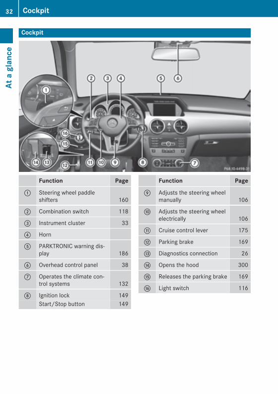
Cockpit
Function Page
: Steering wheel paddleshifters 160
; Combination switch 118
= Instrument cluster 33
? Horn
A PARKTRONIC warning dis-play 186
B Overhead control panel 38
C Operates the climate con-trol systems 132
D Ignition lock 149Start/Stop button 149
Function Page
E Adjusts the steering wheelmanually 106
F Adjusts the steering wheelelectrically 106
G Cruise control lever 175
H Parking brake 169
I Diagnostics connection 26
J Opens the hood 300
K Releases the parking brake 169
L Light switch 116
32 CockpitAt
a g
lanc
e
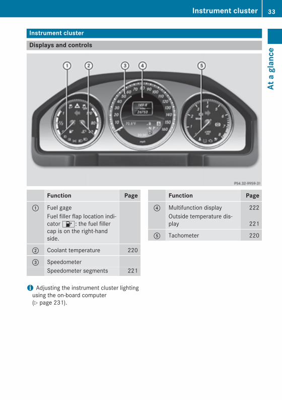
Instrument cluster
Displays and controls
Function Page
: Fuel gageFuel filler flap location indi-cator 8: the fuel fillercap is on the right-handside.
; Coolant temperature 220
= SpeedometerSpeedometer segments 221
Function Page
? Multifunction display 222Outside temperature dis-play 221
A Tachometer 220
i Adjusting the instrument cluster lightingusing the on-board computer(Y page 231).
Instrument cluster 33
At a
gla
nce
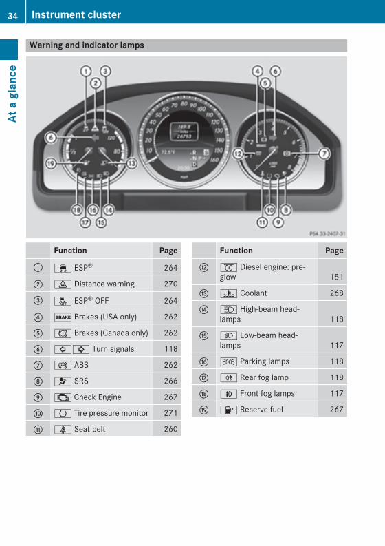
Warning and indicator lamps
Function Page
: ÷ ESP® 264
; · Distance warning 270
= å ESP® OFF 264
? $ Brakes (USA only) 262
A J Brakes (Canada only) 262
B #! Turn signals 118
C ! ABS 262
D 6 SRS 266
E ; Check Engine 267
F h Tire pressure monitor 271
G ü Seat belt 260
Function Page
H % Diesel engine: pre-glow 151
I ? Coolant 268
J K High-beam head-lamps 118
K L Low-beam head-lamps 117
L T Parking lamps 118
M R Rear fog lamp 118
N N Front fog lamps 117
O 8 Reserve fuel 267
34 Instrument clusterAt
a g
lanc
e
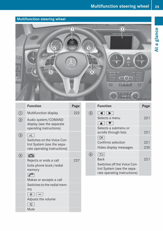
Multifunction steering wheel
Function Page
: Multifunction display 222
; Audio system/COMANDdisplay (see the separateoperating instructions)
= ?
Switches on the Voice Con-trol System (see the sepa-rate operating instructions)
? ~
Rejects or ends a call 227Exits phone book/redialmemory6
Makes or accepts a callSwitches to the redial mem-oryW XAdjusts the volume8
Mute
Function Page
A = ;Selects a menu 2219 :Selects a submenu orscrolls through lists 221a
Confirms selection 221Hides display messages 235
B %
Back 221Switches off the Voice Con-trol System (see the sepa-rate operating instructions)
Multifunction steering wheel 35
At a
gla
nce
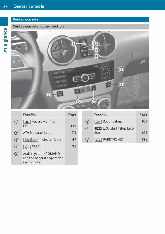
Center console
Center console, upper section
Function Page
: £ Hazard warninglamps 119
; ATA indicator lamp 75
= 45 Indicator lamp 49
? å ESP® 71
A Audio system/COMAND;see the separate operatinginstructions
Function Page
B c Seat heating 105
C ¤ ECO start/stop func-tion 153
D c PARKTRONIC 186
36 Center consoleAt
a g
lanc
e
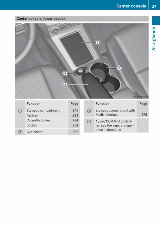
Center console, lower section
Function Page
: Stowage compartment 275Ashtray 283Cigarette lighter 284Socket 284
; Cup holder 282
Function Page
= Stowage compartment withMedia Interface 275
? Audio/COMAND control-ler; see the separate oper-ating instructions
Center console 37
At a
gla
nce
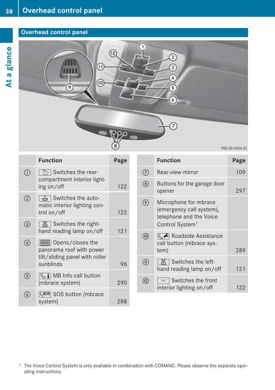
Overhead control panel
Function Page
: u Switches the rear-compartment interior light-ing on/off 122
; | Switches the auto-matic interior lighting con-trol on/off 122
= p Switches the right-hand reading lamp on/off 121
? 3 Opens/closes thepanorama roof with powertilt/sliding panel with rollersunblinds 96
A ï MB Info call button(mbrace system) 290
B G SOS button (mbracesystem) 288
Function Page
C Rear-view mirror 109
D Buttons for the garage dooropener 297
E Microphone for mbrace(emergency call system),telephone and the VoiceControl System1
F F Roadside Assistancecall button (mbrace sys-tem) 289
G p Switches the left-hand reading lamp on/off 121
H c Switches the frontinterior lighting on/off 122
1 The Voice Control System is only available in combination with COMAND. Please observe the separate oper-ating instructions.
38 Overhead control panelAt
a g
lanc
e
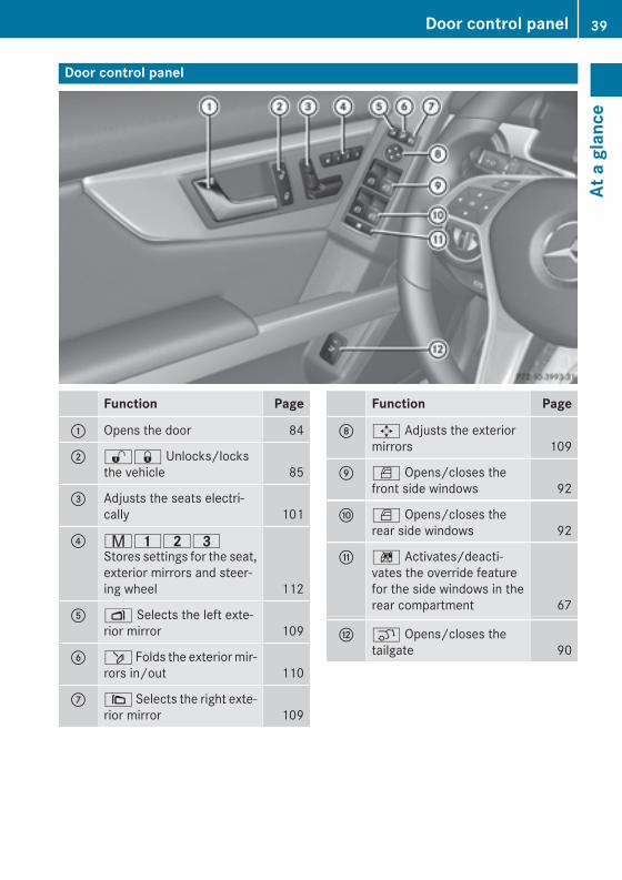
Door control panel
Function Page
: Opens the door 84
; %& Unlocks/locksthe vehicle 85
= Adjusts the seats electri-cally 101
? r45=Stores settings for the seat,exterior mirrors and steer-ing wheel 112
A Z Selects the left exte-rior mirror 109
B ö Folds the exterior mir-rors in/out 110
C \ Selects the right exte-rior mirror 109
Function Page
D 7 Adjusts the exteriormirrors 109
E W Opens/closes thefront side windows 92
F W Opens/closes therear side windows 92
G n Activates/deacti-vates the override featurefor the side windows in therear compartment 67
H q Opens/closes thetailgate 90
Door control panel 39
At a
gla
nce

40

Useful information .............................. 42Panic alarm .......................................... 42Occupant safety .................................. 42Children in the vehicle ........................ 61Pets in the vehicle ............................... 67Driving safety systems ....................... 68Protection against theft ..................... 74
41
Safe
ty

Useful information
i This Operator's Manual describes allmodels and all standard and optional equip-ment of your vehicle available at the time ofpublication of the Operator's Manual.Country-specific differences are possible.Please note that your vehicle may not beequipped with all features described. Thisalso applies to safety-related systems andfunctions.
i Read the information on qualified special-ist workshops (Y page 27).
Panic alarm
X To activate: press ! button : forapproximately one second.A visual and audible alarm is triggered if thealarm system is armed.
X To deactivate: press ! button :again.
orX Insert the SmartKey into the ignition lock.or, on vehicles with KEYLESS‑GO,X Press the KEYLESS-GO Start/Stop button.
The KEYLESS-GO key must be in the vehi-cle.
Occupant safety
Overview of occupant safetyIn this section, you will learn the most impor-tant facts about the restraint system compo-nents of the vehicle.The restraint system consists of:Rseat beltsRchild restraint systemsRLATCH-type (ISOFIX) child seat anchorsAdditional protection is provided by:RSRS (Supplemental Restraint System)RNECK-PRO head restraints/NECK-PRO
luxury head restraintsRair bag system components with:
- PASSENGER AIR BAG OFF indicator lamp- front-passenger seat with Occupant
Classification System (OCS)The different air bag systems work independ-ently of each other. The protective functionsof the system work in conjunction with eachother. Not all air bags are always deployed inan accident.
G WARNINGModifications to or work improperly conduc-ted on restraint system components or theirwiring, as well as tampering with interconnec-ted electronic systems, can lead to therestraint systems no longer functioning asintended.Air bags or Emergency Tensioning Devices(ETDs), for example, could deploy inadver-tently or fail to deploy in accidents althoughthe deceleration threshold for air bag deploy-ment is exceeded. Therefore, never modifythe restraint systems. Do not tamper withelectronic components or their software.
i For information on infants and childrentraveling with you in the vehicle restraintsystems for infants and children, see "Chil-dren in the vehicle" .
42 Occupant safetySa
fety
SRS (Supplemental Restraint System)
IntroductionSupplemental Restraint System (SRS) with:RThe 6 SRS warning lampRAir bagsRAir bag control unit (with crash sensors)REmergency Tensioning Device (ETD) for
seat beltsRSeat belt force limitersSRS reduces the risk of vehicle occupantscoming into contact with parts of the vehi-cle's interior in the event of an accident. It canalso reduce the forces to which vehicle occu-pants are subjected during an accident.
SRS warning lamp
G WARNINGIf SRS is malfunctioning, restraint systemcomponents may be triggered unintentionallyor might not be triggered at all in the event ofan accident with a high rate of vehicle decel-eration. There is an increased risk of injury,possibly even fatal.Have SRS checked and repaired immediatelyat a qualified specialist workshop.
SRS functions are checked regularly whenyou switch on the ignition and when theengine is running. Therefore, malfunctionscan be detected in good time.The 6 SRS warning lamp in the instrumentcluster lights up when the ignition is switchedon. It goes out no later than a few secondsafter the engine is started.The SRS components are in operational read-iness when the 6 SRS warning lamp goesout while the engine is running.
There is a malfunction if:Rthe 6 SRS warning lamp does not light
up when the ignition is switched onRthe engine is running and the 6 SRS
warning lamp does not go out after a fewsecondsRthe engine is running and the 6 SRS
warning lamp lights up again
Safety guidelines for seat belts, Emer-gency Tensioning Devices (ETDs) andair bags
G WARNINGRDamaged seat belts or seat belts that have
been subjected to stress in an accidentmust be replaced. Their anchoring pointsmust also be checked. Only use seat beltsinstalled or supplied by an authorizedMercedes-Benz Center.RAir bags and pyrotechnic Emergency Ten-
sioning Devices (ETDs) contain perchloratematerial, which may require special han-dling and regard for the environment.Check your national disposal guidelines.California residents, seewww.dtsc.ca.gov/HazardousWaste/Perchlorate/index.cfm.RAir bags and ETDs are designed to function
on a one-time-only basis. An air bag or ETDthat has deployed must be replaced.RDo not pass seat belts over sharp edges.
They could tear.RDo not make any modification that could
change the effectiveness of the seat belts.RDo not bleach or dye seat belts as this may
severely weaken them. In a crash they maynot be able to provide adequate protection.RNo modifications of any kind may be made
to any components or wiring of the SRS.RDo not change or remove any component or
part of the SRS.RDo not install additional trim material, seat
covers, badges, etc. over the steeringwheel hub, front-passenger front air bag
Occupant safety 43
Safe
ty
Z
cover, outer sides of the seat backrests,door trim panels, or door frame trims.RDo not install additional electrical/elec-
tronic equipment on or near SRS compo-nents and wiring.RKeep area between air bags and occupants
free of objects (e.g. packages, purses,umbrellas, etc.).RDo not hang items such as coat hangers
from the coat hooks or handles over thedoor. These items may be thrown around inthe vehicle and cause head and other inju-ries when the window curtain air bag isdeployed.RAir bag system components will be hot after
an air bag has inflated. Do not touch them.RNever place your feet on the instrument
panel, dashboard, or on the seat. Alwayskeep both feet on the floor in front of theseat.RImproper repair work on the SRS creates a
risk of rendering the SRS inoperative orcausing unintended air bag deployment.Work on the SRS must therefore only beperformed by qualified technicians. Con-tact an authorized Mercedes-Benz Center.RFor your protection and the protection of
others, when scrapping the air bag unit orETD, our safety instructions must be fol-lowed. These instructions are availablefrom any authorized Mercedes-Benz Cen-ter.RGiven the considerable deployment speed,
required inflation volume, and the materialof the air bags, there is the possibility ofabrasions or other, potentially more seriousinjuries resulting from air bag deployment.
If you sell your vehicle, Mercedes-Benzstrongly recommends that you inform thesubsequent owner that the vehicle is equip-ped with SRS. Also, refer them to the appli-cable section in the Operator's Manual.
Air bags
Important safety notesThe air bag installation locations are identi-fied by the AIR BAG symbol.
G WARNINGUsing unsuitable seat covers could restrict oreven prevent deployment of the air bags inte-grated into the seats. Consequently, the airbags cannot protect vehicle occupants asthey are designed to do. In addition, the func-tion of the air bag deactivation system couldbe restricted. This poses an increased risk ofinjury or even fatal injury.You should only use seat covers that havebeen approved for the respective seat byMercedes-Benz.
You should only use seat covers that havebeen approved for your vehicle by Mercedes-Benz. The seat covers must have a specialtear seam for side impact air bags. Otherwise,the side impact air bags cannot deploy cor-rectly and therefore cannot provide the inten-ded protection in the event of an accident.
G WARNINGThe air bag parts are hot after an air bag hasbeen deployed. There is a risk of injury.Do not touch the air bag parts. Have adeployed air bag replaced at a qualified spe-cialist workshop as soon as possible.
G WARNINGAir bags are designed to reduce the incidenceof injuries and fatalities in certain situations:Rfrontal impacts (driver's and front-
passenger front air bags and driver's kneebag)Rside impacts (side impact air bags, window
curtain air bags and pelvis air bags)Rrollover (window curtain air bags)However, no system available today can com-pletely eliminate injuries and fatalities.
44 Occupant safetySa
fety
When the air bags are deployed, a smallamount of powder is released. The powdergenerally does not constitute a health hazardand does not indicate that there is a fire in thevehicle. In order to prevent potential breath-ing difficulties, you should leave the vehicle assoon as it is safe to do so. If you have anybreathing difficulty but cannot get out of thevehicle after the air bag inflates, then get freshair by opening a window or door.
G WARNINGIn order to reduce the potential danger ofinjuries caused during the deployment of thefront air bags, the driver and front passengermust always be correctly seated and weartheir seat belts.For maximum protection in the event of a col-lision, you must always be in the normal seatposition with your back against the backrest.Fasten your seat belt and make sure that it iscorrectly positioned on your body.As the air bag inflates with considerablespeed and force, a proper seating positionand correct positioning of the hands on thesteering wheel will help to keep you at a safedistance from the air bag. Occupants who arenot wearing their seat belt, are not seatedproperly or are too close to the air bag can beseriously injured or killed by an air bag, as itinflates with great force instantaneously:Rsit with the seat belt fastened correctly and
in a position that is as upright as possiblewith your back against the backrest.Rmove the driver's seat as far back as pos-
sible, still permitting proper operation ofvehicle controls. The distance from the cen-ter of the driver's chest to the center of theair bag cover on the steering wheel must beat least 10 inches (25 cm). You should beable to accomplish this by adjusting theseat and steering wheel. If you have anydifficulties, please contact an authorizedMercedes-Benz Center.Rdo not lean your head or chest close to the
steering wheel or dashboard.
Ronly hold the steering wheel on the outside.Placing hands and arms inside the rim canincrease the risk and potential severity ofhand/arm injury if the driver front air baginflates.Radjust the front-passenger seat as far back
as possible from the dashboard when theseat is occupied.Roccupants, especially children, should
never place their bodies or lean their headsin the area of the door where the sideimpact air bag inflates. This could result inserious or fatal injuries should the sideimpact air bag be deployed. Always sit asupright as possible, wear the seat belt prop-erly and use an appropriately sized infantrestraint, toddler restraint or booster seatrecommended for the size and weight of thechild.
Failure to follow these instructions can resultin severe injuries to you or other occupants.If you sell your vehicle, it is important that youmake the buyer aware of this safety informa-tion. Be sure to give the buyer this Operator'sManual.
If the air bags are deployed, you will hear abang, and a small amount of powder may alsobe released. Only in rare cases will the bangaffect your hearing. The powder that isreleased generally does not constitute ahealth hazard and does not indicate that thereis a fire in the vehicle. The dust might causesome temporary breathing difficulty for peo-ple with asthma or other breathing trouble. Toavoid this, you may wish to get out of thevehicle or open the windows as soon as it issafe to do so. The 6 SRS warning lamplights up.The air bags are deployed if the air bag controlunit detects the need for deployment. Only inthe event of such a situation will the air bagsprovide their supplemental protection.If the driver and front passenger do not weartheir seat belts, it is not possible for the airbags to provide their supplemental protec-tion.
Occupant safety 45
Safe
ty
Z
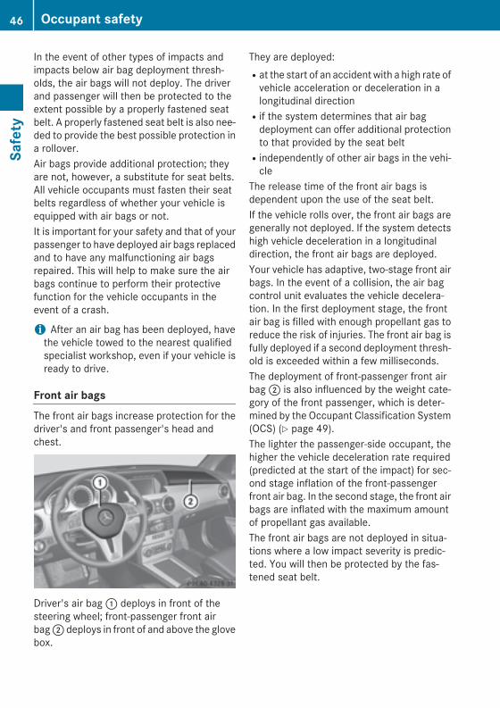
In the event of other types of impacts andimpacts below air bag deployment thresh-olds, the air bags will not deploy. The driverand passenger will then be protected to theextent possible by a properly fastened seatbelt. A properly fastened seat belt is also nee-ded to provide the best possible protection ina rollover.Air bags provide additional protection; theyare not, however, a substitute for seat belts.All vehicle occupants must fasten their seatbelts regardless of whether your vehicle isequipped with air bags or not.It is important for your safety and that of yourpassenger to have deployed air bags replacedand to have any malfunctioning air bagsrepaired. This will help to make sure the airbags continue to perform their protectivefunction for the vehicle occupants in theevent of a crash.
i After an air bag has been deployed, havethe vehicle towed to the nearest qualifiedspecialist workshop, even if your vehicle isready to drive.
Front air bagsThe front air bags increase protection for thedriver's and front passenger's head andchest.
Driver's air bag : deploys in front of thesteering wheel; front-passenger front airbag ; deploys in front of and above the glovebox.
They are deployed:Rat the start of an accident with a high rate of
vehicle acceleration or deceleration in alongitudinal directionRif the system determines that air bag
deployment can offer additional protectionto that provided by the seat beltRindependently of other air bags in the vehi-
cleThe release time of the front air bags isdependent upon the use of the seat belt.If the vehicle rolls over, the front air bags aregenerally not deployed. If the system detectshigh vehicle deceleration in a longitudinaldirection, the front air bags are deployed.Your vehicle has adaptive, two-stage front airbags. In the event of a collision, the air bagcontrol unit evaluates the vehicle decelera-tion. In the first deployment stage, the frontair bag is filled with enough propellant gas toreduce the risk of injuries. The front air bag isfully deployed if a second deployment thresh-old is exceeded within a few milliseconds.The deployment of front-passenger front airbag ; is also influenced by the weight cate-gory of the front passenger, which is deter-mined by the Occupant Classification System(OCS) (Y page 49).The lighter the passenger-side occupant, thehigher the vehicle deceleration rate required(predicted at the start of the impact) for sec-ond stage inflation of the front-passengerfront air bag. In the second stage, the front airbags are inflated with the maximum amountof propellant gas available.The front air bags are not deployed in situa-tions where a low impact severity is predic-ted. You will then be protected by the fas-tened seat belt.
46 Occupant safetySa
fety
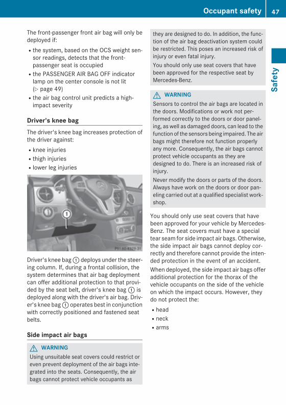
The front-passenger front air bag will only bedeployed if:Rthe system, based on the OCS weight sen-
sor readings, detects that the front-passenger seat is occupiedRthe PASSENGER AIR BAG OFF indicator
lamp on the center console is not lit(Y page 49)Rthe air bag control unit predicts a high-
impact severity
Driver's knee bagThe driver's knee bag increases protection ofthe driver against:Rknee injuriesRthigh injuriesRlower leg injuries
Driver's knee bag : deploys under the steer-ing column. If, during a frontal collision, thesystem determines that air bag deploymentcan offer additional protection to that provi-ded by the seat belt, driver's knee bag : isdeployed along with the driver's air bag. Driv-er's knee bag : operates best in conjunctionwith correctly positioned and fastened seatbelts.
Side impact air bags
G WARNINGUsing unsuitable seat covers could restrict oreven prevent deployment of the air bags inte-grated into the seats. Consequently, the airbags cannot protect vehicle occupants as
they are designed to do. In addition, the func-tion of the air bag deactivation system couldbe restricted. This poses an increased risk ofinjury or even fatal injury.You should only use seat covers that havebeen approved for the respective seat byMercedes-Benz.
G WARNINGSensors to control the air bags are located inthe doors. Modifications or work not per-formed correctly to the doors or door panel-ing, as well as damaged doors, can lead to thefunction of the sensors being impaired. The airbags might therefore not function properlyany more. Consequently, the air bags cannotprotect vehicle occupants as they aredesigned to do. There is an increased risk ofinjury.Never modify the doors or parts of the doors.Always have work on the doors or door pan-eling carried out at a qualified specialist work-shop.
You should only use seat covers that havebeen approved for your vehicle by Mercedes-Benz. The seat covers must have a specialtear seam for side impact air bags. Otherwise,the side impact air bags cannot deploy cor-rectly and therefore cannot provide the inten-ded protection in the event of an accident.When deployed, the side impact air bags offeradditional protection for the thorax of thevehicle occupants on the side of the vehicleon which the impact occurs. However, theydo not protect the:RheadRneckRarms
Occupant safety 47
Safe
ty
Z
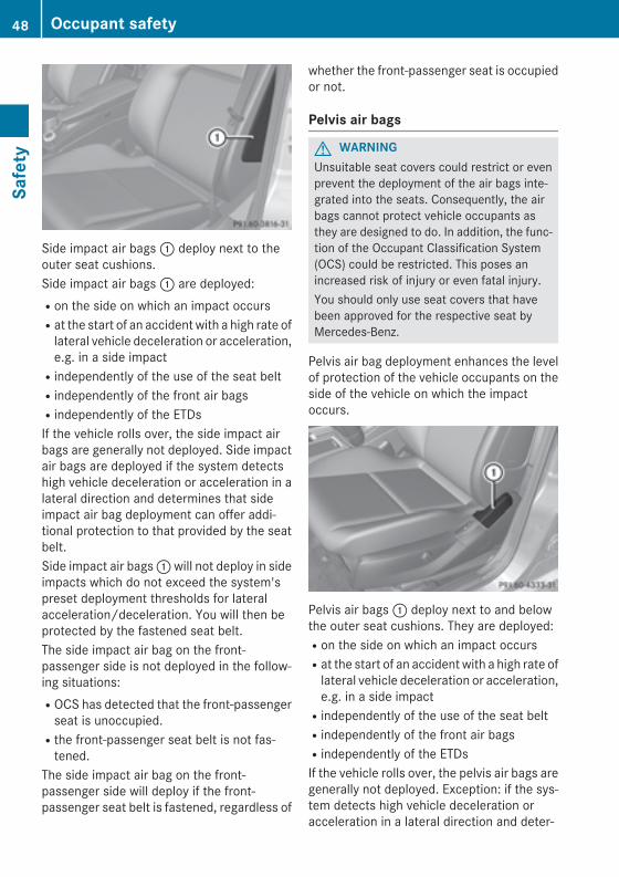
Side impact air bags : deploy next to theouter seat cushions.Side impact air bags : are deployed:Ron the side on which an impact occursRat the start of an accident with a high rate of
lateral vehicle deceleration or acceleration,e.g. in a side impactRindependently of the use of the seat beltRindependently of the front air bagsRindependently of the ETDsIf the vehicle rolls over, the side impact airbags are generally not deployed. Side impactair bags are deployed if the system detectshigh vehicle deceleration or acceleration in alateral direction and determines that sideimpact air bag deployment can offer addi-tional protection to that provided by the seatbelt.Side impact air bags : will not deploy in sideimpacts which do not exceed the system'spreset deployment thresholds for lateralacceleration/deceleration. You will then beprotected by the fastened seat belt.The side impact air bag on the front-passenger side is not deployed in the follow-ing situations:ROCS has detected that the front-passenger
seat is unoccupied.Rthe front-passenger seat belt is not fas-
tened.The side impact air bag on the front-passenger side will deploy if the front-passenger seat belt is fastened, regardless of
whether the front-passenger seat is occupiedor not.
Pelvis air bags
G WARNINGUnsuitable seat covers could restrict or evenprevent the deployment of the air bags inte-grated into the seats. Consequently, the airbags cannot protect vehicle occupants asthey are designed to do. In addition, the func-tion of the Occupant Classification System(OCS) could be restricted. This poses anincreased risk of injury or even fatal injury.You should only use seat covers that havebeen approved for the respective seat byMercedes-Benz.
Pelvis air bag deployment enhances the levelof protection of the vehicle occupants on theside of the vehicle on which the impactoccurs.
Pelvis air bags : deploy next to and belowthe outer seat cushions. They are deployed:Ron the side on which an impact occursRat the start of an accident with a high rate of
lateral vehicle deceleration or acceleration,e.g. in a side impactRindependently of the use of the seat beltRindependently of the front air bagsRindependently of the ETDsIf the vehicle rolls over, the pelvis air bags aregenerally not deployed. Exception: if the sys-tem detects high vehicle deceleration oracceleration in a lateral direction and deter-
48 Occupant safetySa
fety
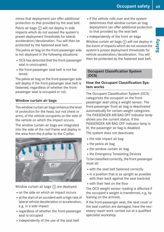
mines that deployment can offer additionalprotection to that provided by the seat belt.Pelvis air bags : will not deploy in sideimpacts which do not exceed the system'spreset deployment thresholds for lateralacceleration/deceleration. You will then beprotected by the fastened seat belt.The pelvis air bag on the front-passenger sideis not deployed in the following situations:ROCS has detected that the front-passenger
seat is unoccupied.Rthe front-passenger seat belt is not fas-
tened.The pelvis air bag on the front-passenger sidewill deploy if the front-passenger seat belt isfastened, regardless of whether the front-passenger seat is occupied or not.
Window curtain air bagsThe window curtain air bags enhance the levelof protection for the head, but not chest orarms, of the vehicle occupants on the side ofthe vehicle on which the impact occurs.The window curtain air bags are integratedinto the side of the roof frame and deploy inthe area from the A-pillar to the C-pillar.
Window curtain air bags : are deployed:Ron the side on which an impact occursRat the start of an accident with a high rate of
lateral vehicle deceleration or acceleration,e.g. in a side impactRregardless of whether the front-passenger
seat is occupiedRindependently of the use of the seat belt
Rif the vehicle rolls over and the systemdetermines that window curtain air bagdeployment can offer additional protectionto that provided by the seat beltRindependently of the front air bagsWindow curtain air bags : will not deploy inthe event of impacts which do not exceed thesystem's preset deployment thresholds forvehicle acceleration/deceleration. You willthen be protected by the fastened seat belt.
Occupant Classification System(OCS)
How the Occupant Classification Sys-tem worksThe Occupant Classification System (OCS)categorizes the occupant on the front-passenger seat using a weight sensor. Thefront-passenger front air bag is deactivatedautomatically for certain weight categories.The PASSENGER AIR BAG OFF indicator lampshows you the current status. If thePASSENGER AIR BAG OFF indicator lamp islit, the passenger air bag is disabled.The system does not deactivate:Rthe side impact air bagRthe pelvis air bagRthe window curtain air bagRthe Emergency Tensioning DevicesTo be classified correctly, the front passengermust sit:Rwith the seat belt fastened correctlyRin a position that is as upright as possible
with their back against the seat backrestRwith their feet on the floorThe OCS weight sensor reading is affected ifthe occupant's weight is transferred, e.g. byleaning on the armrest.If the front-passenger seat, the seat cover orthe seat cushion are damaged, have the nec-essary repair work carried out at a qualifiedspecialist workshop.
Occupant safety 49
Safe
ty
Z
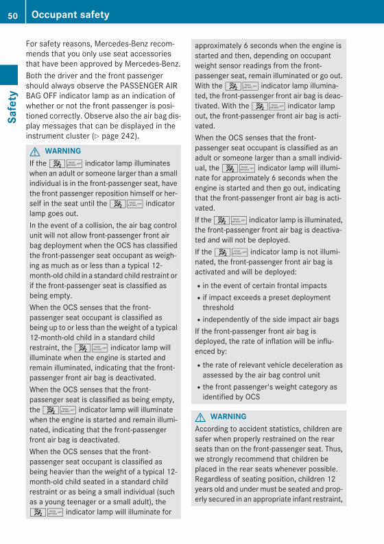
For safety reasons, Mercedes-Benz recom-mends that you only use seat accessoriesthat have been approved by Mercedes-Benz.Both the driver and the front passengershould always observe the PASSENGER AIRBAG OFF indicator lamp as an indication ofwhether or not the front passenger is posi-tioned correctly. Observe also the air bag dis-play messages that can be displayed in theinstrument cluster (Y page 242).
G WARNINGIf the 45 indicator lamp illuminateswhen an adult or someone larger than a smallindividual is in the front-passenger seat, havethe front passenger reposition himself or her-self in the seat until the 45 indicatorlamp goes out.In the event of a collision, the air bag controlunit will not allow front-passenger front airbag deployment when the OCS has classifiedthe front-passenger seat occupant as weigh-ing as much as or less than a typical 12-month-old child in a standard child restraint orif the front-passenger seat is classified asbeing empty.When the OCS senses that the front-passenger seat occupant is classified asbeing up to or less than the weight of a typical12-month-old child in a standard childrestraint, the 45 indicator lamp willilluminate when the engine is started andremain illuminated, indicating that the front-passenger front air bag is deactivated.When the OCS senses that the front-passenger seat is classified as being empty,the 45 indicator lamp will illuminatewhen the engine is started and remain illumi-nated, indicating that the front-passengerfront air bag is deactivated.When the OCS senses that the front-passenger seat occupant is classified asbeing heavier than the weight of a typical 12-month-old child seated in a standard childrestraint or as being a small individual (suchas a young teenager or a small adult), the45 indicator lamp will illuminate for
approximately 6 seconds when the engine isstarted and then, depending on occupantweight sensor readings from the front-passenger seat, remain illuminated or go out.With the 45 indicator lamp illumina-ted, the front-passenger front air bag is deac-tivated. With the 45 indicator lampout, the front-passenger front air bag is acti-vated.When the OCS senses that the front-passenger seat occupant is classified as anadult or someone larger than a small individ-ual, the 45 indicator lamp will illumi-nate for approximately 6 seconds when theengine is started and then go out, indicatingthat the front-passenger front air bag is acti-vated.If the 45 indicator lamp is illuminated,the front-passenger front air bag is deactiva-ted and will not be deployed.If the 45 indicator lamp is not illumi-nated, the front-passenger front air bag isactivated and will be deployed:Rin the event of certain frontal impactsRif impact exceeds a preset deployment
thresholdRindependently of the side impact air bagsIf the front-passenger front air bag isdeployed, the rate of inflation will be influ-enced by:Rthe rate of relevant vehicle deceleration as
assessed by the air bag control unitRthe front passenger's weight category as
identified by OCS
G WARNINGAccording to accident statistics, children aresafer when properly restrained on the rearseats than on the front-passenger seat. Thus,we strongly recommend that children beplaced in the rear seats whenever possible.Regardless of seating position, children 12years old and under must be seated and prop-erly secured in an appropriate infant restraint,
50 Occupant safetySa
fety
toddler restraint, or booster seat recommen-ded for the size and weight of the child.The infant or child restraint must be properlysecured with the vehicle's seat belt, the seatbelt and Top Tether strap, or lower anchorsand Top Tether strap, fully in accordance withthe child seat manufacturer's instructions.Occupants, especially children, should alwayssit as upright as possible, wear the seat beltproperly and use an appropriately sized infantrestraint, toddler restraint, or booster seatrecommended for the size and weight of thechild.Children can be killed or seriously injured byan inflating air bag. Note the following impor-tant information when circumstances requireyou to place a child in the front-passengerseat:RYour vehicle is equipped with air bag tech-
nology designed to deactivate the front-passenger front air bag in your vehiclewhen the system senses the weight of atypical 12-month-old child or less alongwith the weight of a standard appropriatechild restraint on the front-passenger seat.RA child in a rear-facing child restraint on the
front-passenger seat will be seriouslyinjured or even killed if the front-passengerfront air bag inflates in a collision whichcould occur under some circumstances,even with the air bag technology installed inyour vehicle. The only means to eliminatethis risk completely is never to place a childin a rear-facing child restraint in the front-passenger seat. We therefore strongly rec-ommend that you always place a child in arear-facing child restraint on the rear seat.RIf you install a rear-facing child restraint on
the front-passenger seat, make sure the45 indicator lamp is illuminated,indicating that the front-passenger front airbag is deactivated. Should the 45indicator lamp not illuminate or go out whilethe restraint is installed, please checkinstallation. Periodically check the45 indicator lamp while driving to
make sure that the 45 indicatorlamp is illuminated. If the 45 indi-cator lamp goes out or remains out, do nottransport a child on the front-passengerseat until the system has been repaired.A child in a rear-facing child restraint on thefront-passenger seat will be seriouslyinjured or even killed if the front-passengerfront air bag inflates.RIf you place a child in a forward-facing child
restraint on the front-passenger seat:- move the seat as far back as possible- use the proper child restraint recommen-
ded for the age, size and weight of thechild
- secure child restraint with the vehicle'sseat belt according to the child seat man-ufacturer's instructions
RFor children larger than the typical 12-month-old child, the front-passenger frontair bag may or may not be activated.
If the driver's air bag deploys, this does notmean that the front-passenger front air bagwill also deploy.The OCS may have detected that the seat:Ris empty or occupied by the weight of a
typical child up to twelve months old,seated in a child restraint system.Ris occupied by a small individual, such as a
young teenager or a small adult.Ris occupied by a child in a child restraint
system whose weight is greater than that ofa typical twelve month old child.
These are examples of when the OCS deacti-vates the front-passenger front air bag. Deac-tivation takes place although the collision ful-fills the criteria for deploying the driver's airbag.
Occupant safety 51
Safe
ty
Z
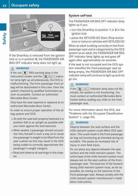
If the SmartKey is removed from the ignitionlock or is in position 0, the PASSENGER AIRBAG OFF indicator lamp does not light up.
G WARNINGIf the red 6 SRS warning lamp in theinstrument cluster and the 45 indica-tor lamp light up simultaneously, the OCS ismalfunctioning. The front passenger front airbag will be deactivated in this case. Have thesystem checked by qualified technicians assoon as possible. Contact an authorizedMercedes-Benz Center.Only have the seat repaired or replaced at anauthorized Mercedes-Benz Center.In order to ensure proper operation of the airbag system and OCS:RSit with the seat belt properly fastened in a
position that is as upright as possible withyour back against the seat backrest.RWhen seated, a passenger should not posi-
tion him/herself in such a way as to causethe passenger's weight to be lifted from theseat cushion as this may result in the OCSbeing unable to correctly approximate thepassenger's weight category.RRead and observe all warnings in this chap-
ter.
System self-testThe PASSENGER AIR BAG OFF indicator lamplights up if you:Rturn the SmartKey to position 1 or 2 in the
ignition lockRpress the KEYLESS-GO Start/Stop button
once or twice on vehicles with KEYLESS-GOWhen an adult is sitting correctly on the front-passenger seat and is categorized by the OCSsystem as an adult, the PASSENGER AIR BAGOFF indicator lamp lights up and goes offagain after approximately six seconds.If the seat is not occupied and the OCS sys-tem classifies the front-passenger seat asbeing empty, the PASSENGER AIR BAG OFFindicator lamp will continue to light up and notgo out.
G WARNINGIf the 4 5 indicator lamp does not illu-minate, the system is not functioning. Youmust contact an authorized Mercedes-BenzCenter before seating any child on the frontpassenger seat.
For more information about the OCS, see"Problems with the Occupant ClassificationSystem" (Y page 53).
G WARNINGObjects between the seat surface and thechild restraint system could affect OCS oper-ation. This could result in the front-passengerair bag not functioning as intended during anaccident. This poses an increased risk ofinjury or even fatal injury.Do not place any objects between the seatsurface and the child restraint system. Theentire base of the child restraint system mustalways rest on the seat cushion of the front-passenger seat. The backrest of the forward-facing child restraint system must, as far aspossible, be resting on the backrest of thefront-passenger seat. Always comply with thechild restraint system manufacturer's instal-lation instructions.
52 Occupant safetySa
fety
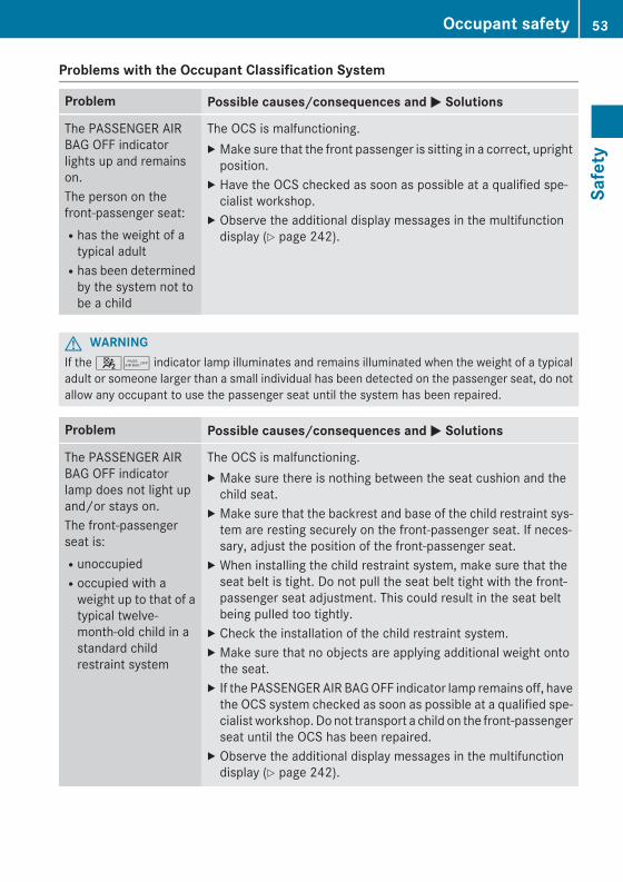
Problems with the Occupant Classification System
Problem Possible causes/consequences and M Solutions
The PASSENGER AIRBAG OFF indicatorlights up and remainson.The person on thefront-passenger seat:Rhas the weight of a
typical adultRhas been determined
by the system not tobe a child
The OCS is malfunctioning.X Make sure that the front passenger is sitting in a correct, upright
position.X Have the OCS checked as soon as possible at a qualified spe-
cialist workshop.X Observe the additional display messages in the multifunction
display (Y page 242).
G WARNINGIf the 45 indicator lamp illuminates and remains illuminated when the weight of a typicaladult or someone larger than a small individual has been detected on the passenger seat, do notallow any occupant to use the passenger seat until the system has been repaired.
Problem Possible causes/consequences and M Solutions
The PASSENGER AIRBAG OFF indicatorlamp does not light upand/or stays on.The front-passengerseat is:RunoccupiedRoccupied with a
weight up to that of atypical twelve-month-old child in astandard childrestraint system
The OCS is malfunctioning.X Make sure there is nothing between the seat cushion and the
child seat.X Make sure that the backrest and base of the child restraint sys-
tem are resting securely on the front-passenger seat. If neces-sary, adjust the position of the front-passenger seat.
X When installing the child restraint system, make sure that theseat belt is tight. Do not pull the seat belt tight with the front-passenger seat adjustment. This could result in the seat beltbeing pulled too tightly.
X Check the installation of the child restraint system.X Make sure that no objects are applying additional weight onto
the seat.X If the PASSENGER AIR BAG OFF indicator lamp remains off, have
the OCS system checked as soon as possible at a qualified spe-cialist workshop. Do not transport a child on the front-passengerseat until the OCS has been repaired.
X Observe the additional display messages in the multifunctiondisplay (Y page 242).
Occupant safety 53
Safe
ty
Z
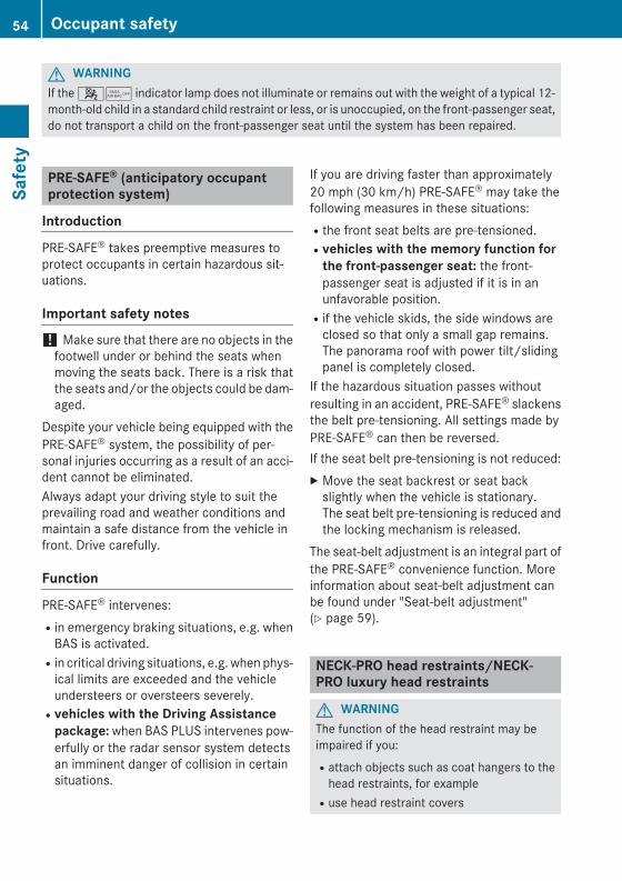
G WARNINGIf the 45 indicator lamp does not illuminate or remains out with the weight of a typical 12-month-old child in a standard child restraint or less, or is unoccupied, on the front-passenger seat,do not transport a child on the front-passenger seat until the system has been repaired.
PRE-SAFE® (anticipatory occupantprotection system)
Introduction
PRE-SAFE® takes preemptive measures toprotect occupants in certain hazardous sit-uations.
Important safety notes
! Make sure that there are no objects in thefootwell under or behind the seats whenmoving the seats back. There is a risk thatthe seats and/or the objects could be dam-aged.
Despite your vehicle being equipped with thePRE-SAFE® system, the possibility of per-sonal injuries occurring as a result of an acci-dent cannot be eliminated.Always adapt your driving style to suit theprevailing road and weather conditions andmaintain a safe distance from the vehicle infront. Drive carefully.
Function
PRE-SAFE® intervenes:Rin emergency braking situations, e.g. when
BAS is activated.Rin critical driving situations, e.g. when phys-
ical limits are exceeded and the vehicleundersteers or oversteers severely.Rvehicles with the Driving Assistance
package: when BAS PLUS intervenes pow-erfully or the radar sensor system detectsan imminent danger of collision in certainsituations.
If you are driving faster than approximately20 mph (30 km/h) PRE-SAFE® may take thefollowing measures in these situations:Rthe front seat belts are pre-tensioned.Rvehicles with the memory function for
the front-passenger seat: the front-passenger seat is adjusted if it is in anunfavorable position.Rif the vehicle skids, the side windows are
closed so that only a small gap remains.The panorama roof with power tilt/slidingpanel is completely closed.
If the hazardous situation passes withoutresulting in an accident, PRE-SAFE® slackensthe belt pre-tensioning. All settings made byPRE-SAFE® can then be reversed.If the seat belt pre-tensioning is not reduced:X Move the seat backrest or seat back
slightly when the vehicle is stationary.The seat belt pre-tensioning is reduced andthe locking mechanism is released.
The seat-belt adjustment is an integral part ofthe PRE-SAFE® convenience function. Moreinformation about seat-belt adjustment canbe found under "Seat-belt adjustment"(Y page 59).
NECK-PRO head restraints/NECK-PRO luxury head restraints
G WARNINGThe function of the head restraint may beimpaired if you:Rattach objects such as coat hangers to the
head restraints, for exampleRuse head restraint covers
54 Occupant safetySa
fety
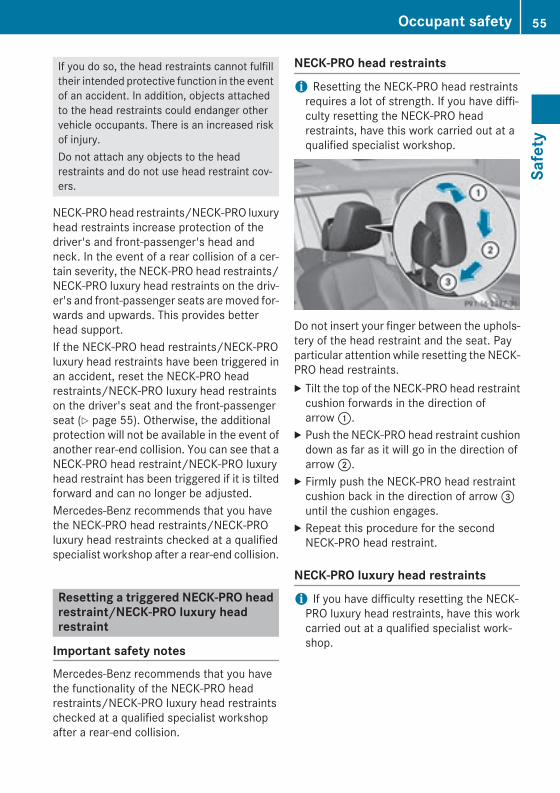
If you do so, the head restraints cannot fulfilltheir intended protective function in the eventof an accident. In addition, objects attachedto the head restraints could endanger othervehicle occupants. There is an increased riskof injury.Do not attach any objects to the headrestraints and do not use head restraint cov-ers.
NECK-PRO head restraints/NECK-PRO luxuryhead restraints increase protection of thedriver's and front-passenger's head andneck. In the event of a rear collision of a cer-tain severity, the NECK-PRO head restraints/NECK-PRO luxury head restraints on the driv-er's and front-passenger seats are moved for-wards and upwards. This provides betterhead support.If the NECK-PRO head restraints/NECK-PROluxury head restraints have been triggered inan accident, reset the NECK-PRO headrestraints/NECK-PRO luxury head restraintson the driver's seat and the front-passengerseat (Y page 55). Otherwise, the additionalprotection will not be available in the event ofanother rear-end collision. You can see that aNECK-PRO head restraint/NECK-PRO luxuryhead restraint has been triggered if it is tiltedforward and can no longer be adjusted.Mercedes-Benz recommends that you havethe NECK-PRO head restraints/NECK-PROluxury head restraints checked at a qualifiedspecialist workshop after a rear-end collision.
Resetting a triggered NECK-PRO headrestraint/NECK-PRO luxury headrestraint
Important safety notesMercedes-Benz recommends that you havethe functionality of the NECK-PRO headrestraints/NECK-PRO luxury head restraintschecked at a qualified specialist workshopafter a rear-end collision.
NECK-PRO head restraints
i Resetting the NECK-PRO head restraintsrequires a lot of strength. If you have diffi-culty resetting the NECK-PRO headrestraints, have this work carried out at aqualified specialist workshop.
Do not insert your finger between the uphols-tery of the head restraint and the seat. Payparticular attention while resetting the NECK-PRO head restraints.X Tilt the top of the NECK-PRO head restraint
cushion forwards in the direction ofarrow :.
X Push the NECK-PRO head restraint cushiondown as far as it will go in the direction ofarrow ;.
X Firmly push the NECK-PRO head restraintcushion back in the direction of arrow =until the cushion engages.
X Repeat this procedure for the secondNECK-PRO head restraint.
NECK-PRO luxury head restraints
i If you have difficulty resetting the NECK-PRO luxury head restraints, have this workcarried out at a qualified specialist work-shop.
Occupant safety 55
Safe
ty
Z

Do not insert your finger between the cushionof the head restraint and the cover. Pay par-ticular attention while resetting the NECK-PRO luxury head restraints.X Remove resetting tool : from the vehicle
document wallet.X Slide resetting tool : into guide ;
between the NECK-PRO luxury headrestraint and the rear cover of the headrestraint.
X Push resetting tool : downwards until youhear the head restraint deployment mech-anism engage.
X Pull out resetting tool :.X Firmly press back the NECK-PRO luxury
head restraint cushion until it engages =.X Repeat this procedure for the second
NECK-PRO luxury head restraint.X Put resetting tool : back into the vehicle
document wallet.
Seat belts
Important safety notesThe use of seat belts and child restraint sys-tems is required by law in:Rall 50 statesRthe U.S. territoriesRthe District of ColumbiaRall Canadian provincesEven where this is not required by law, allvehicle occupants should correctly fastentheir seat belts before starting the journey.
i See "Children in the vehicle" for furtherinformation on infants and children travel-ing in the vehicle as well as on childrestraint systems.
G WARNINGThe seat belt does not offer the intended levelof protection if you have not moved the back-rest to an almost vertical position. When brak-ing or in the event of an accident, you couldslide underneath the seat belt and sustainabdomen or neck injuries, for example. Thisposes an increased risk of injury or even fatalinjury.Adjust the seat properly before beginningyour journey. Always ensure that the backrestis in an almost vertical position and that theshoulder section of your seat belt is routedacross the center of your shoulder.
G WARNINGThe seat belts may not perform their intendedprotective function if:Rthey are damaged, modified, extremely
dirty, bleach or dyedRthe seat belt buckle is damaged or
extremely dirtyRthe Emergency Tensioning Devices, belt
anchorages or inertia reels have been modi-fied
Seat belts may sustain non-visible damage inan accident, e.g. due to glass splinters. Modi-fied or damaged seat belts may tear or fail,e.g. in an accident. Modified Emergency Ten-sioning Devices could accidentally trigger orfail to deploy when necessary. This poses anincreased risk of injury or even fatal injury.Never modify the seat belts, Emergency Ten-sioning Devices, belt anchorages or inertiareels. Make sure that the seat belts areundamaged, not worn out and clean. Follow-ing an accident, have the seat belts checkedimmediately at a qualified specialist work-shop.
Only use seat belts that have been approvedfor your vehicle by Mercedes-Benz. Any such
56 Occupant safetySa
fety
modifications could invalidate the vehicle'sgeneral operating permit.The use of seat belts and child restraint sys-tems is required by law in:Rall 50 statesRthe U.S. territoriesRthe District of ColumbiaRall Canadian provincesEven where this is not required by law, allvehicle occupants should correctly fastentheir seat belts before starting the journey.
i See "Children in the vehicle" for furtherinformation on infants and children travel-ing in the vehicle, as well as on childrestraint systems.
Proper use of the seat belts
G WARNINGUSE SEAT BELTS PROPERLYRSeat belts can only work when used prop-
erly. Never wear seat belts in any other waythan as described in this section, as thatcould result in serious injuries in the eventof an accident.REach occupant should wear their seat belt
at all times, because seat belts help reducethe likelihood of and potential severity ofinjuries in accidents, including rollovers.The integrated restraint system includesSRS (driver front air bag, driver's side kneebag, front-passenger front air bag, sideimpact air bags, pelvis air bags, windowcurtain air bags for the side windows),Emergency Tensioning Devices, seat beltforce limiters, and front seat knee bolsters.The system is designed to enhance the pro-tection offered to properly belted occu-pants in certain frontal (front air bags, driv-er's side knee bag and ETDs) and side (sideimpact air bags, window curtain air bags,and ETDs) impacts which exceed presetdeployment thresholds and in certain roll-overs (window curtain air bags and ETDs).
RNever wear the shoulder belt under yourarm, across your neck or off your shoulder.In a frontal crash, your body would movetoo far forward. That would increase thechance of head and neck injuries. The seatbelt would also apply too much force to theribs or abdomen, which could severelyinjure internal organs such as your liver orspleen.Adjust the seat belt so that the shouldersection is located as close as possible tothe middle of the shoulder. It should nottouch the neck. Never pass the shoulderportion of the seat belt under your arm. Forthis purpose, you can adjust the height ofthe seat belt outlet.RPosition the lap belt as low as possible on
your hips and not across the abdomen. Ifthe lap belt is positioned across your abdo-men, it could cause serious injuries in acrash.RNever wear seat belts over rigid or breaka-
ble objects in or on your clothing, such aseyeglasses, pens, keys etc., as these mightcause injuries.RMake sure the seat belt is always fitted
snugly. Take special care of this when wear-ing loose clothing.RNever use a seat belt for more than one
person at a time. Do not fasten a seat beltaround a person and another person orother objects at the same time.RSeat belts should not be worn twisted. In a
crash, you would not have the full width ofthe seat belt to distribute impact forces.The twisted seat belt against your bodycould cause injuries.RPregnant women should also always use a
lap-shoulder belt. The lap belt portionshould be positioned as low as possible onthe hips to avoid any possible pressure onthe abdomen.RPlace the seat backrest in a position that is
as upright as possible.RCheck your seat belt during travel to make
sure it is properly positioned.
Occupant safety 57
Safe
ty
Z
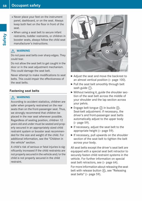
RNever place your feet on the instrumentpanel, dashboard, or on the seat. Alwayskeep both feet on the floor in front of theseat.RWhen using a seat belt to secure infant
restraints, toddler restraints, or children inbooster seats, always follow the child seatmanufacturer's instructions.
G WARNINGDo not pass seat belts over sharp edges. Theycould tear.Do not allow the seat belt to get caught in thedoor or in the seat adjustment mechanism.This could damage the seat belt.Never attempt to make modifications to seatbelts. This could impair the effectiveness ofthe seat belts.
Fastening seat belts
G WARNINGAccording to accident statistics, children aresafer when properly restrained on the rearseats than on the front-passenger seat. Thus,we strongly recommend that children beplaced in the rear seat whenever possible.Regardless of seating position, children 12years old and under must be seated and prop-erly secured in an appropriately sized childrestraint system or booster seat recommen-ded for the size and weight of the child. Foradditional information, see the "Children inthe vehicle" section.A child's risk of serious or fatal injuries is sig-nificantly increased if the child restraints arenot properly secured in the vehicle and/or thechild is not properly secured in the childrestraint.
X Adjust the seat and move the backrest toan almost vertical position (Y page 100).
X Pull the seat belt smoothly through beltsash guide :.
X Without twisting it, guide the shoulder sec-tion of the seat belt across the middle ofyour shoulder and the lap section acrossyour pelvis.
X Engage belt tongue ; in buckle =.Seat-belt adjustment: if necessary, thedriver's and front-passenger seat beltsautomatically adjust to the upper body(Y page 59).
X If necessary, adjust the seat belt to theappropriate height (Y page 59).
X If necessary, pull upwards on the shouldersection of the seat belt to tighten the beltacross your body.
All seat belts except the driver's seat belt areequipped with a special seat belt retractor tosecurely fasten child restraint systems in thevehicle. For further information on specialseat belt retractors, see (Y page 64).For more information about releasing the seatbelt with release button ?, see "Releasingseat belts" (Y page 59).
58 Occupant safetySa
fety
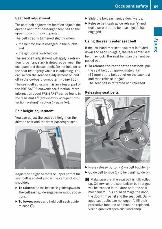
Seat belt adjustmentThe seat-belt adjustment function adjusts thedriver's and front-passenger seat belt to theupper body of the occupants.The belt strap is tightened slightly when:Rthe belt tongue is engaged in the buckle
andRthe ignition is switched onThe seat-belt adjustment will apply a retrac-tion force if any slack is detected between theoccupant and the seat belt. Do not hold on tothe seat belt tightly while it is adjusting. Youcan switch the seat-belt adjustment on andoff in the on-board computer (Y page 233).The seat-belt adjustment is an integral part ofthe PRE-SAFE® convenience function. Moreinformation about PRE-SAFE® can be found inthe "PRE-SAFE® (anticipatory occupant pro-tection system)" section (Y page 54).
Belt height adjustmentYou can adjust the seat belt height on thedriver's seat and the front-passenger seat.
Adjust the height so that the upper part of theseat belt is routed across the center of yourshoulder.X To raise: slide the belt sash guide upwards.
The belt sash guide engages in various posi-tions.
X To lower: press and hold belt sash guiderelease :.
X Slide the belt sash guide downwards.X Release belt sash guide release : and
make sure that the belt sash guide hasengaged.
Using the rear center seat beltIf the left-hand rear seat backrest is foldeddown and back up again, the rear center seatbelt may lock. The seat belt can then not bepulled out.X To release the rear center seat belt: pull
the seat belt out approximately 1 in(25 mm) at the belt outlet on the backrestand then release it again.The seat belt is retracted and released.
Releasing seat belts
X Press release button ? on belt buckle =.X Guide belt tongue ; to belt sash guide :.
! Make sure that the seat belt is fully rolledup. Otherwise, the seat belt or belt tonguewill be trapped in the door or in the seatmechanism. This could damage the door,the door trim panel and the seat belt. Dam-aged seat belts can no longer fulfill theirprotective function and must be replaced.Visit a qualified specialist workshop.
Occupant safety 59
Safe
ty
Z
Belt warning for the driver and frontpassengerRegardless of whether the driver's and front-passenger seat belts have already been fas-tened, the 7 seat belt warning lamp lightsup for six seconds each time the engine isstarted. It then goes out if the driver and thefront passenger have already fastened theirseat belts.If the driver's seat belt is not fastened whenthe engine is started, an additional warningtone will sound. This warning tone stops aftera maximum of six seconds or once the driv-er's seat belt is fastened.If after six seconds the driver or frontpassenger have not fastened their seat beltsand the doors are closed, the 7 seat beltwarning lamp lights up:Runtil the driver's or front passenger's seat
belt is fastenedRif a vehicle speed of 15 mph (25 km/h) is
exceeded, a warning tone also sounds withincreasing intensity for a maximum of60 seconds or until the driver or front-passenger seat belt has been fastened
If the driver/front passenger unfasten theirseat belt while the vehicle is in motion, the7 seat belt warning lamp lights up and awarning tone sounds again.The warning tone ceases even if the driver orfront-passenger seat belt has still not beenfastened after 60 seconds. The 7 seat beltwarning lamp stops flashing but remains illu-minated.After the vehicle comes to a standstill, thewarning tone is reactivated and the 7 seatbelt warning lamp flashes again if the vehiclespeed again exceeds 15 mph (25 km/h).The 7 seat belt warning lamp only goesout if:Rboth the driver and the front passenger
have fastened their seat belts.orRthe vehicle is stationary and a door is open.
i For more information on the 7 seatbelt warning lamp, see "Warning and indi-cator lamps in the instrument cluster, seatbelts" (Y page 260).
Emergency Tensioning Devices, seatbelt force limiters
G WARNINGPyrotechnic Emergency Tensioning Devicesthat have been deployed are no longer opera-tional and are unable to perform their inten-ded protective function. This poses anincreased risk of injury or even fatal injury.Therefore, have pyrotechnic Emergency Ten-sioning Devices which have been triggeredimmediately replaced at a qualified specialistworkshop.
! If the front-passenger seat is unoccupied,do not insert the belt tongue into the buckleof the front-passenger seat. This may oth-erwise lead to the triggering of the Emer-gency Tensioning Device in the event of anaccident, which will then need to bereplaced.
i Vehicles with PRE-SAFE®: an electricmotor is used by PRE-SAFE® to trigger thetightening of the seat belt in hazardous sit-uations. This procedure is reversible.
The seat belts for the front seats and rearouter seats are equipped with EmergencyTensioning Devices and seat belt force limit-ers.The ETDs tighten the seat belts in an accident,pulling them close against the body.The ETDs do not correct incorrect seat posi-tions or incorrectly fastened seat belts.The ETDs do not pull vehicle occupants backtowards the backrest.The ETDs can only be activated when:Rthe ignition is switched onRthe restraint systems are operational; see
"SRS warning lamp "(Y page 43)
60 Occupant safetySa
fety
Rthe belt tongue is engaged in the buckle oneach of the lap-shoulder belts in the frontRthe front-passenger seat is occupied and
the belt tongue is engaged in the buckle onthe front-passenger side
The ETDs on the outside seats in the rearcompartment are triggered independently ofthe lock status of the seat belts.The Emergency Tensioning Devices are trig-gered depending on the type and severity ofan accident, if:Rin certain situations where the vehicle rolls
over and the system determines that it canprovide additional protectionRin the event of a head-on or rear-end colli-
sion, the vehicle decelerates or acceleratesrapidly in a longitudinal direction during theinitial stages of the impactRin the event of a side impact, the vehicle
decelerates or accelerates rapidly in a lat-eral direction on the side opposite theimpact
If the ETDs are deployed, you will hear a bang,and a small amount of powder may also bereleased. Only in rare cases will the bangaffect your hearing. The powder that isreleased generally does not constitute ahealth hazard and does not indicate that thereis a fire in the vehicle. The dust might causesome temporary breathing difficulty for peo-ple with asthma or other breathing trouble. Toavoid this, you may wish to get out of thevehicle or open the windows as soon as it issafe to do so. The 6 SRS warning lamplights up.If the seat belt is also equipped with a seatbelt force limiter and this is triggered, theforce exerted by the seat belt on the vehicleoccupant is reduced.The seat belt force limiters for the front seatsare synchronized with the front air bags,which absorb part of the deceleration force.This results in the force exerted on the occu-pant being distributed over a greater area.
Children in the vehicle
Child restraint systems
Important safety notesMercedes-Benz recommends that you alwaysproperly secure all infants and children with achild or infant seat restraint system for thetrip.The use of seat belts and infant and childrestraint systems is required by law in:Rall 50 statesRthe U.S. territoriesRthe District of ColumbiaRall Canadian provincesInfants and children must always be seated inan appropriate infant or child restraint systemrecommended for the size and weight of thechild. The infant or child restraint systemmust be properly secured in accordance withthe manufacturer's instructions.All infant or child restraint systems must meetthe following standards:RU.S. Federal Motor Vehicle Safety Stand-
ards 213 and 225RCanadian Motor Vehicle Safety Standards
213 and 210.2Confirmation that the child restraint systemcorresponds to the standards can be foundon an instruction label on the child restraintsystem. This confirmation can also be foundin the installation instructions that are inclu-ded with the child restraint system.Always read and follow the manufacturer'sinstructions when using an infant or childrestraint system or booster seat.Observe the warning labels in the vehicle inte-rior or on the infant or child restraint.
G WARNINGAccording to accident statistics, children aresafer when properly restrained in the rearseating positions than in the front seatingposition. Thus, we strongly recommend thatchildren be placed in the rear seats whenever
Children in the vehicle 61
Safe
ty
Z
possible. Regardless of seating position, chil-dren 12 years old and under must be seatedand properly secured in an appropriate infantrestraint, toddler restraint, or booster seatrecommended for the size and weight of thechild.The infant or child restraint must be properlysecured with the vehicle's seat belt, the seatbelt and top tether strap, or lower anchors andtop tether strap, fully in accordance with thechild seat manufacturer's instructions.Occupants, especially children, should alwayssit as upright as possible, wear the seat beltproperly and use an appropriately sized infantrestraint, toddler restraint, or booster seatrecommended for the size and weight of thechild.Children can be killed or seriously injured byan inflating air bag. Note the following impor-tant information when circumstances requireyou to place a child in the front passengerseat:RYour vehicle is equipped with air bag tech-
nology designed to deactivate the frontpassenger front air bag in your vehiclewhen the system senses the weight of atypical 12‑month-old child or less alongwith the weight of a standard appropriatechild restraint on the front passenger seat.RFor children larger than the typical
12‑month-old child, the front passengerfront air bag may or may not be activated.Always make sure the 4 5 indicatorlamp is illuminated, indicating that the frontpassenger front air bag is deactivated.RA child in a rear-facing child restraint on the
front passenger seat will be seriouslyinjured or even killed if the front passengerfront air bag inflates in a collision whichcould occur under some circumstances,even with the air bag technology installed inyour vehicle. The only means to completelyeliminate this risk is to never place a child ina rear-facing child restraint in the frontseat. We therefore strongly recommend
that you always place a child in a rear-facingchild restraint in a backseat.RIf you must install a rear-facing child
restraint on the front passenger seatbecause circumstances require you to doso, make sure the 4 5 indicatorlamp is illuminated, indicating that the frontpassenger front air bag is deactivated.Should the 4 5 indicator lamp notilluminate or go out while the restraint isinstalled, please check installation. Period-ically check the 4 5 indicator lampwhile driving to make sure the 4 5indicator lamp is illuminated. If the 45 indicator lamp goes out or remainsout, do not transport a child on the frontpassenger seat until the system has beenrepaired.A child in a rear-facing child restraint on thefront passenger seat will be seriouslyinjured or even killed if the front passengerfront air bag inflates.RIf you have to place a child in a forward-
facing child restraint on the front passengerseat, move the seat as far back as possible,use the proper child restraint recommen-ded for the age, size and weight of the child,and secure child restraint with the vehicle'sseat belt according to the child seat man-ufacturer's instructions.
G WARNINGIf the child restraint system is installed incor-rectly on a suitable seat, it cannot protect asintended. The child cannot then be restrainedin the event of an accident, heavy braking orsudden changes of direction. There is anincreased risk of injury, possibly even fatal.Make sure that you observe the child restraintsystem manufacturer's installation instruc-tions and the notes on use. Please ensure,that the base of the child restraint system isalways resting completely on the seat cush-ion. Never place objects, e.g. cushions, underor behind the child restraint system. Only usechild restraint systems with the original cover
62 Children in the vehicleSa
fety

designed for them. Only replace damagedcovers with genuine covers.
G WARNINGIf the child restraint system is installed incor-rectly or is not secured, it can come loose inthe event of an accident, heavy braking or asudden change in direction. The childrestraint system could be thrown about, strik-ing vehicle occupants. There is an increasedrisk of injury, possibly even fatal.Always install child restraint systems prop-erly, even if they are not being used. Makesure that you observe the child restraint sys-tem manufacturer's installation instructions.
G WARNINGChild restraint systems or their securing sys-tems which have been damaged or subjectedto a load in an accident can no longer protectas intended. The child cannot then berestrained in the event of an accident, heavybraking or sudden changes of direction. Thereis an increased risk of injury, possibly evenfatal.Replace child restraint systems which havebeen damaged or subjected to a load in anaccident as soon as possible. Have the secur-ing systems on the child restraint systemchecked at a qualified specialist workshop,before you install a child restraint systemagain.
The securing systems of child restraint sys-tems are:Rthe seat belt systemRthe LATCH-type (ISOFIX) securing ringsRthe Top Tether anchorages
G WARNINGInfants and small children should never sharea seat belt with another occupant. In the eventof an accident, they could be crushedbetween the occupant and seat belt.A child's risk of serious or fatal injuries is sig-nificantly increased if the child restraints are
not properly secured in the vehicle and/or thechild is not properly secured in the childrestraint.Children that are too large for a child restraintmust travel in seats using normal seat belts.Position the shoulder belt across the chestand shoulder, not the face or neck. A boosterseat may be necessary to achieve proper seatbelt positioning for children over 41 lbs(18 kg) until they reach a height where a lap/shoulder belt fits properly without a boosterseat.When the child restraint is not in use, removeit from the vehicle or secure it with the seatbelt to prevent the child restraint from becom-ing a projectile in the event of an accident.
G WARNINGIf children are left unsupervised in the vehicle,they could:Ropen the doors, thus endangering other
people or road users.Rget out and disrupt traffic.Roperate the vehicle's equipment.Additionally, children could set the vehicle inmotion if, for example, they:Rrelease the parking brake.Rshifting the automatic transmission out of
park position PRStart the engine.There is a risk of an accident and injury.When leaving the vehicle, always take theSmartKey with you and lock the vehicle. Neverleave children or animals unattended in thevehicle. Always keep the SmartKey out ofreach of children.
G WARNINGIf persons, particularly children are subjectedto prolonged exposure to extreme heat orcold, there is a risk of injury, possibly evenfatal. Never leave children unattended in thevehicle.
Children in the vehicle 63
Safe
ty
Z
G WARNINGIf the child restraint system is subjected todirect sunlight, parts may get very hot. Chil-dren may burn themselves on these parts,particularly on the metal parts of the childrestraint system. There is a risk of injury.If you leave the vehicle, taking the child withyou, always ensure that the child restraintsystem is not exposed to direct sunlight. Pro-tect it with a blanket, for example. If the childrestraint system has been exposed to directsunlight, let it cool down before securing thechild in it. Never leave children unattended inthe vehicle.
If an infant or child is traveling in the vehicle:X Secure the child with a child or infant seat
restraint system appropriate to the age andweight of the child.
X Make sure that the infant or child is prop-erly secured at all times while the vehicle isin motion.
Special seat belt retractorAll seat belts except the driver's seat belt areequipped with a special seat belt retractor.When activated, the special seat belt retrac-tor ensures that the seat belt will not slackenonce the child restraint system has beensecured.Installing a child restraint system:X Always comply with the manufacturer's
installation instructions.X Pull the seat belt smoothly from the seat
belt retractor.X Engage the seat belt tongue in the belt
buckle.
Activating the special seat belt retractor:X Pull the seat belt out fully and let the seat
belt retractor retract it again.While the seat belt is retracting, you shouldhear a ratcheting sound. The special seatbelt retractor is activated.
X Push down on the child restraint system totake up any slack.
Removing a child restraint system/deactivat-ing the special seat belt retractor:X Always comply with the manufacturer's
installation instructions.X Press the release button on the belt buckle,
hold the belt tongue firmly and guide it backtowards the belt sash guide.The special seat belt retractor is deactiva-ted.
G WARNINGIf the seat belt is released while driving, thechild restraint system will no longer besecured properly. The special seat belt retrac-tor is disabled and the inertia real draws in aportion of the seat belt. The seat belt cannotbe immediately refastened. There is anincreased risk of injury, possibly even fatal.Stop the vehicle immediately, paying atten-tion to road and traffic conditions. Reactivatethe special seat belt retractor and secure thechild restraint system properly.
LATCH-type (ISOFIX) child seat anchorsin the rear
G WARNINGChildren that are too large for a child restraintmust travel in seats using normal seat belts.Position shoulder belt across the chest andshoulder, not face or neck.A booster seat may be necessary to achieveproper seat belt positioning for children over41 lb (18 kg) until they reach a height where alap/shoulder belt fits properly without a boos-ter.
64 Children in the vehicleSa
fety
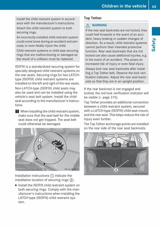
Install the child restraint system in accord-ance with the manufacturer's instructions.Attach the child restraint system to bothsecuring rings.An incorrectly installed child restraint systemcould come loose during an accident and seri-ously or even fatally injure the child.Child restraint systems or child seat securingrings that are malfunctioning or damaged asthe result of a collision must be replaced.
ISOFIX is a standardized securing system forspecially designed child restraint systems onthe rear seats. Securing rings for two LATCH-type (ISOFIX) child restraint systems areinstalled on the left and right of the rear seats.Non-LATCH-type (ISOFIX) child seats mayalso be used and can be installed using thevehicle's seat belt system. Install the childseat according to the manufacturer's instruc-tions.
! When installing the child restraint system,make sure that the seat belt for the middleseat does not get trapped. The seat beltcould otherwise be damaged.
Installation instructions : indicate theinstallation location of securing rings 2.X Install the ISOFIX child restraint system on
both securing rings. Comply with the man-ufacturer's instructions when installing theLATCH-type (ISOFIX) child restraint sys-tem.
Top Tether
G WARNINGIf the rear seat backrests are not locked, theycould fold forwards in the event of an acci-dent, heavy braking or sudden changes ofdirection. As a result, child restraint systemscannot perform their intended protectivefunction. Rear seat backrests that are notlocked can also cause additional injuries, e.g.in the event of an accident. This poses anincreased risk of injury or even fatal injury.Always lock rear seat backrests after instal-ling a Top Tether belt. Observe the lock veri-fication indicator. Adjust the rear seat backr-ests so that they are in an upright position.
If the rear backrest is not engaged andlocked, the red lock verification indicator willbe visible (Y page 276).Top Tether provides an additional connectionbetween a child restraint system, securedwith a LATCH-type (ISOFIX) child seat mount,and the rear seat. This helps reduce the risk ofinjury even further.The Top Tether anchorage points are installedon the rear side of the rear seat backrests.
Children in the vehicle 65
Safe
ty
Z
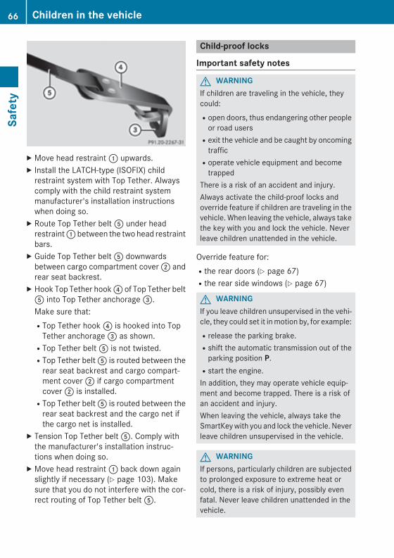
X Move head restraint : upwards.X Install the LATCH-type (ISOFIX) child
restraint system with Top Tether. Alwayscomply with the child restraint systemmanufacturer's installation instructionswhen doing so.
X Route Top Tether belt A under headrestraint : between the two head restraintbars.
X Guide Top Tether belt A downwardsbetween cargo compartment cover ; andrear seat backrest.
X Hook Top Tether hook ? of Top Tether beltA into Top Tether anchorage =.Make sure that:RTop Tether hook ? is hooked into Top
Tether anchorage = as shown.RTop Tether belt A is not twisted.RTop Tether belt A is routed between the
rear seat backrest and cargo compart-ment cover ; if cargo compartmentcover ; is installed.RTop Tether belt A is routed between the
rear seat backrest and the cargo net ifthe cargo net is installed.
X Tension Top Tether belt A. Comply withthe manufacturer's installation instruc-tions when doing so.
X Move head restraint : back down againslightly if necessary (Y page 103). Makesure that you do not interfere with the cor-rect routing of Top Tether belt A.
Child-proof locks
Important safety notes
G WARNINGIf children are traveling in the vehicle, theycould:Ropen doors, thus endangering other people
or road usersRexit the vehicle and be caught by oncoming
trafficRoperate vehicle equipment and become
trappedThere is a risk of an accident and injury.Always activate the child-proof locks andoverride feature if children are traveling in thevehicle. When leaving the vehicle, always takethe key with you and lock the vehicle. Neverleave children unattended in the vehicle.
Override feature for:Rthe rear doors (Y page 67)Rthe rear side windows (Y page 67)
G WARNINGIf you leave children unsupervised in the vehi-cle, they could set it in motion by, for example:Rrelease the parking brake.Rshift the automatic transmission out of the
parking position P.Rstart the engine.In addition, they may operate vehicle equip-ment and become trapped. There is a risk ofan accident and injury.When leaving the vehicle, always take theSmartKey with you and lock the vehicle. Neverleave children unsupervised in the vehicle.
G WARNINGIf persons, particularly children are subjectedto prolonged exposure to extreme heat orcold, there is a risk of injury, possibly evenfatal. Never leave children unattended in thevehicle.
66 Children in the vehicleSa
fety
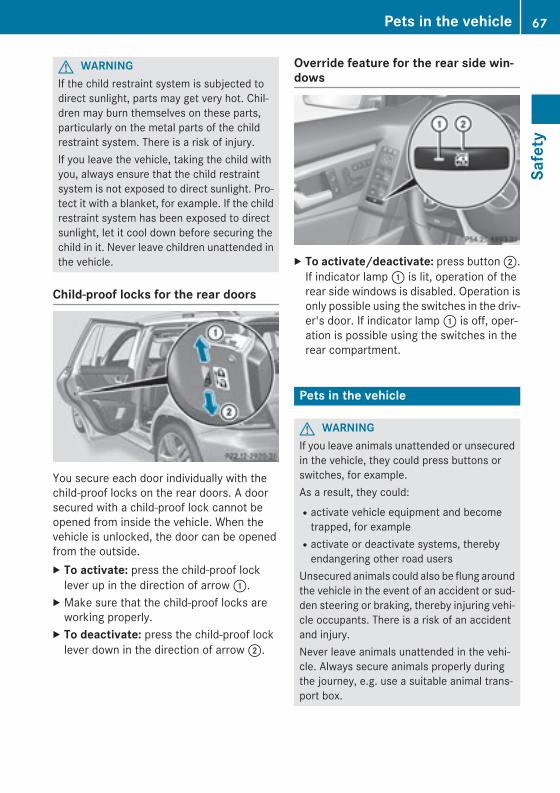
G WARNINGIf the child restraint system is subjected todirect sunlight, parts may get very hot. Chil-dren may burn themselves on these parts,particularly on the metal parts of the childrestraint system. There is a risk of injury.If you leave the vehicle, taking the child withyou, always ensure that the child restraintsystem is not exposed to direct sunlight. Pro-tect it with a blanket, for example. If the childrestraint system has been exposed to directsunlight, let it cool down before securing thechild in it. Never leave children unattended inthe vehicle.
Child-proof locks for the rear doors
You secure each door individually with thechild-proof locks on the rear doors. A doorsecured with a child-proof lock cannot beopened from inside the vehicle. When thevehicle is unlocked, the door can be openedfrom the outside.X To activate: press the child-proof lock
lever up in the direction of arrow :.X Make sure that the child-proof locks are
working properly.X To deactivate: press the child-proof lock
lever down in the direction of arrow ;.
Override feature for the rear side win-dows
X To activate/deactivate: press button ;.If indicator lamp : is lit, operation of therear side windows is disabled. Operation isonly possible using the switches in the driv-er's door. If indicator lamp : is off, oper-ation is possible using the switches in therear compartment.
Pets in the vehicle
G WARNINGIf you leave animals unattended or unsecuredin the vehicle, they could press buttons orswitches, for example.As a result, they could:Ractivate vehicle equipment and become
trapped, for exampleRactivate or deactivate systems, thereby
endangering other road usersUnsecured animals could also be flung aroundthe vehicle in the event of an accident or sud-den steering or braking, thereby injuring vehi-cle occupants. There is a risk of an accidentand injury.Never leave animals unattended in the vehi-cle. Always secure animals properly duringthe journey, e.g. use a suitable animal trans-port box.
Pets in the vehicle 67
Safe
ty
Z
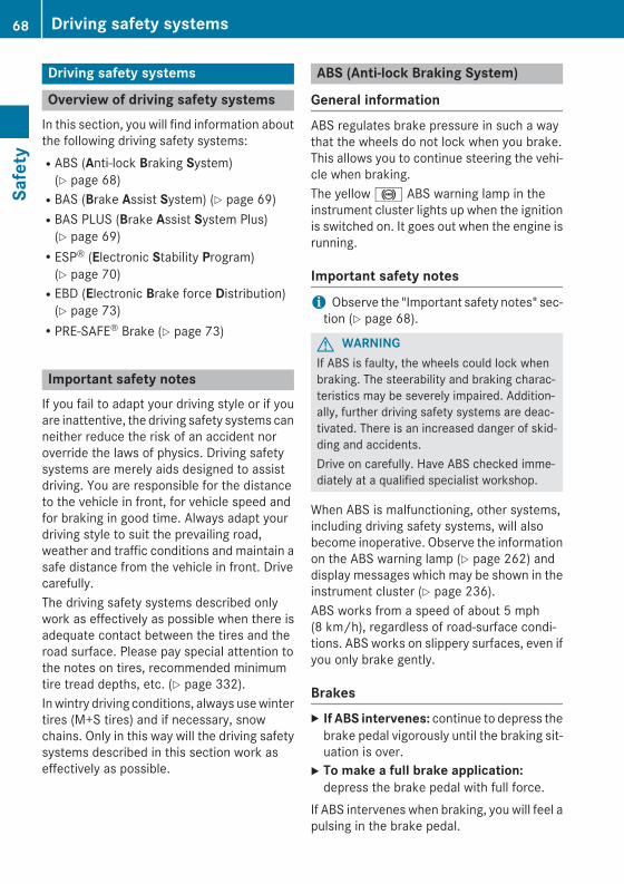
Driving safety systems
Overview of driving safety systemsIn this section, you will find information aboutthe following driving safety systems:RABS (Anti-lock Braking System)
(Y page 68)RBAS (Brake Assist System) (Y page 69)RBAS PLUS (Brake Assist System Plus)
(Y page 69)RESP® (Electronic Stability Program)
(Y page 70)REBD (Electronic Brake force Distribution)
(Y page 73)RPRE-SAFE® Brake (Y page 73)
Important safety notesIf you fail to adapt your driving style or if youare inattentive, the driving safety systems canneither reduce the risk of an accident noroverride the laws of physics. Driving safetysystems are merely aids designed to assistdriving. You are responsible for the distanceto the vehicle in front, for vehicle speed andfor braking in good time. Always adapt yourdriving style to suit the prevailing road,weather and traffic conditions and maintain asafe distance from the vehicle in front. Drivecarefully.The driving safety systems described onlywork as effectively as possible when there isadequate contact between the tires and theroad surface. Please pay special attention tothe notes on tires, recommended minimumtire tread depths, etc. (Y page 332).In wintry driving conditions, always use wintertires (M+S tires) and if necessary, snowchains. Only in this way will the driving safetysystems described in this section work aseffectively as possible.
ABS (Anti-lock Braking System)
General informationABS regulates brake pressure in such a waythat the wheels do not lock when you brake.This allows you to continue steering the vehi-cle when braking.The yellow ! ABS warning lamp in theinstrument cluster lights up when the ignitionis switched on. It goes out when the engine isrunning.
Important safety notes
i Observe the "Important safety notes" sec-tion (Y page 68).
G WARNINGIf ABS is faulty, the wheels could lock whenbraking. The steerability and braking charac-teristics may be severely impaired. Addition-ally, further driving safety systems are deac-tivated. There is an increased danger of skid-ding and accidents.Drive on carefully. Have ABS checked imme-diately at a qualified specialist workshop.
When ABS is malfunctioning, other systems,including driving safety systems, will alsobecome inoperative. Observe the informationon the ABS warning lamp (Y page 262) anddisplay messages which may be shown in theinstrument cluster (Y page 236).ABS works from a speed of about 5 mph(8 km/h), regardless of road-surface condi-tions. ABS works on slippery surfaces, even ifyou only brake gently.
BrakesX If ABS intervenes: continue to depress the
brake pedal vigorously until the braking sit-uation is over.
X To make a full brake application:depress the brake pedal with full force.
If ABS intervenes when braking, you will feel apulsing in the brake pedal.
68 Driving safety systemsSa
fety
The pulsating brake pedal can be an indica-tion of hazardous road conditions, and func-tions as a reminder to take extra care whiledriving.
BAS (Brake Assist System)
General informationBAS operates in emergency braking situa-tions. If you depress the brake pedal quickly,BAS automatically boosts the braking force,thus shortening the stopping distance.
Important safety notes
i Observe the "Important safety notes" sec-tion (Y page 68).
G WARNINGIf BAS is malfunctioning, the braking distancein an emergency braking situation isincreased. There is a risk of an accident.In an emergency braking situation, depressthe brake pedal with full force. ABS preventsthe wheels from locking.
BrakingX Keep the brake pedal firmly depressed until
the emergency braking situation is over.ABS prevents the wheels from locking.
The brakes will function as usual once yourelease the brake pedal. BAS is deactivated.
BAS PLUS (Brake Assist SystemPLUS)
General information
i Observe the "Important safety notes" sec-tion (Y page 68).
BAS PLUS is only available in vehicles equip-ped with DISTRONIC PLUS.For BAS PLUS to assist you, the radar sensorsystem must be operational.
With the help of the radar sensor system, BASPLUS can detect obstacles that are in thepath of your vehicle for an extended period oftime.If the radar sensor system is malfunctioning,BAS PLUS will not be available. The brakesystem is still available with complete brakeboosting effect and BAS.BAS PLUS can help you to minimize the risk ofa collision with a vehicle or reduce the effectsof such a collision. If BAS PLUS detects adanger of collision, you are assisted whenbraking.
Important safety notes
G WARNINGBAS PLUS cannot always clearly identifyobjects and complex traffic situations.In such cases, BAS PLUS may:Rintervene unnecessarilyRnot interveneThere is a risk of an accident.Always pay careful attention to the traffic sit-uation and be ready to brake. Terminate theintervention in a non-critical driving situation.
G WARNINGBAS PLUS does not react:Rto people or animalsRto oncoming vehiclesRto crossing trafficRwhen corneringAs a result, BAS PLUS may not intervene in allcritical situations. There is a risk of an acci-dent.Always pay careful attention to the traffic sit-uation and be ready to brake.
In the event of snowfall or heavy rain, the rec-ognition can be impaired.
Driving safety systems 69
Safe
ty
Z
Recognition by the radar sensor system isalso impaired in the event of:Rthere is dirt on the sensors or anything else
covering the sensorsRthere is interference by other radar sourcesRthere are strong radar reflections, for
example in parking garagesRa narrow vehicle traveling in front, e.g. a
motorbikeRa vehicle traveling in front on a different line
relative to the center of your vehicleFollowing damage to the front end of the vehi-cle, have the configuration and operation ofthe radar sensors checked at a qualified spe-cialist workshop. This also applies to colli-sions at low speeds where there is no visibledamage to the front of the vehicle.
FunctionTo avoid a collision, BAS PLUS calculates thebrake force necessary if:Ryou approach an obstacle, andRBAS PLUS has detected a risk of collisionWhen driving at a speed under 20 mph (30 km/h): if you depress the brake pedal,BAS PLUS is activated. The increase in brakepressure will be carried out at the last possi-ble moment.When driving at a speed above 20 mph (30 km/h): if you depress the brake pedalsharply, BAS PLUS automatically raises thebrake pressure to a value adapted to the traf-fic situation.BAS PLUS provides braking assistance in haz-ardous situations with vehicles in front withina speed range between 4 mph (7 km/h) and155 mph (250 km/h).At speeds of up to approximately 40 mph(70 km/h), BAS PLUS can also react to sta-tionary objects. Examples of stationaryobjects are stopped or parked vehicles.
i If BAS PLUS demands particularly highbraking force, preventative passenger pro-
tection measures (PRE-SAFE®) are activa-ted simultaneously.
X Keep the brake pedal depressed until theemergency braking situation is over.ABS prevents the wheels from locking.
BAS PLUS is deactivated and the brakes func-tion as usual again, if:Ryou release the brake pedal.Rthere is no longer a risk of collision.Rno obstacle is detected in front of your
vehicle.
ESP® (Electronic Stability Program)
General notes
i Observe the "Important safety notes" sec-tion (Y page 68).
ESP® monitors driving stability and traction,i.e. power transmission between the tires andthe road surface.If ESP® detects that the vehicle is deviatingfrom the direction desired by the driver, oneor more wheels are braked to stabilize thevehicle. The engine output is also modified tokeep the vehicle on the desired course withinphysical limits. ESP® assists the driver whenpulling away on wet or slippery roads. ESP®
can also stabilize the vehicle during braking.
ETS/4ETS (Electronic Traction System)
i Observe the "Important safety notes" sec-tion (Y page 68).
ETS traction control is part of ESP®. On vehi-cles with 4MATIC, 4ETS is part of ESP®.Traction control brakes the drive wheels indi-vidually if they spin. This enables you to pullaway and accelerate on slippery surfaces, forexample if the road surface is slippery on oneside. In addition, more drive torque is trans-ferred to the wheel or wheels with traction.Traction control remains active, even if youdeactivate ESP®.
70 Driving safety systemsSa
fety
Important safety notes
i Observe the "Important safety notes" sec-tion (Y page 68).
G WARNINGIf ESP® is malfunctioning, ESP® is unable tostabilize the vehicle. Additionally, further driv-ing safety systems are deactivated. Thisincreases the risk of skidding and an accident.Drive on carefully. Have ESP® checked at aqualified specialist workshop.
! If you test the parking brake using a brakedynamometer, switch the ignition off.Application of the brakes by ESP® may oth-erwise destroy the brake system.
Vehicles without 4MATIC: observe the noteson ESP® (Y page 327) when towing the vehi-cle with a raised rear axle.
! Vehicles with 4MATIC: function or per-formance tests may only be carried out ona 2-axle dynamometer. Before you operatethe vehicle on such a dynamometer, pleaseconsult a qualified workshop. You couldotherwise damage the drive train or thebrake system.
ESP® is only deactivated if the å warninglamp is lit continuously.If the ÷ warning lamp and the å warn-ing lamp are lit continuously, ESP® is notavailable due to a malfunction.Observe the information on warning lamps(Y page 264) and display messages whichmay be shown in the instrument cluster(Y page 236).
i Only use wheels with the recommendedtire sizes. Only then will ESP® functionproperly.
Characteristics of ESP®
General informationIf the ÷ ESP® warning lamp goes outbefore beginning the journey, ESP® is auto-matically active.If ESP® intervenes, the ÷ ESP® warninglamp flashes in the instrument cluster.If ESP® intervenes:X Do not deactivate ESP® under any circum-
stances.X Only depress the accelerator pedal as far as
necessary when pulling away.X Adapt your driving style to suit the prevail-
ing road and weather conditions.
ECO start/stop functionThe ECO start/stop function switches theengine off automatically when the vehiclestops moving. The engine starts automati-cally when the driver wants to pull away again.ESP® remains in its previously selected sta-tus. Example: if ESP® was deactivated beforethe engine was switched off, ESP® remainsdeactivated when the engine is switched onagain.
Deactivating/activating ESP®
Important safety notesi Observe the "Important safety notes" sec-
tion (Y page 68).You can select between the following sta-tuses of ESP:RESP® is activated.RESP® is deactivated.
G WARNINGIf you deactivate ESP®, ESP® no longer sta-bilizes the vehicle. There is an increased riskof skidding and an accident.Only deactivate ESP® in the situations descri-bed in the following.
Driving safety systems 71
Safe
ty
Z
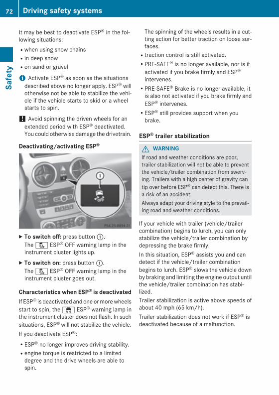
It may be best to deactivate ESP® in the fol-lowing situations:Rwhen using snow chainsRin deep snowRon sand or gravel
i Activate ESP® as soon as the situationsdescribed above no longer apply. ESP® willotherwise not be able to stabilize the vehi-cle if the vehicle starts to skid or a wheelstarts to spin.
! Avoid spinning the driven wheels for anextended period with ESP® deactivated.You could otherwise damage the drivetrain.
Deactivating/activating ESP®
X To switch off: press button :.The å ESP® OFF warning lamp in theinstrument cluster lights up.
X To switch on: press button :.The å ESP® OFF warning lamp in theinstrument cluster goes out.
Characteristics when ESP® is deactivatedIf ESP® is deactivated and one or more wheelsstart to spin, the ÷ ESP® warning lamp inthe instrument cluster does not flash. In suchsituations, ESP® will not stabilize the vehicle.If you deactivate ESP®:RESP® no longer improves driving stability.Rengine torque is restricted to a limited
degree and the drive wheels are able tospin.
The spinning of the wheels results in a cut-ting action for better traction on loose sur-faces.Rtraction control is still activated.RPRE-SAFE® is no longer available, nor is it
activated if you brake firmly and ESP®
intervenes.RPRE-SAFE® Brake is no longer available, it
is also not activated if you brake firmly andESP® intervenes.RESP® still provides support when you
brake.
ESP® trailer stabilization
G WARNINGIf road and weather conditions are poor,trailer stabilization will not be able to preventthe vehicle/trailer combination from swerv-ing. Trailers with a high center of gravity cantip over before ESP® can detect this. There isa risk of an accident.Always adapt your driving style to the prevail-ing road and weather conditions.
If your vehicle with trailer (vehicle/trailercombination) begins to lurch, you can onlystabilize the vehicle/trailer combination bydepressing the brake firmly.In this situation, ESP® assists you and candetect if the vehicle/trailer combinationbegins to lurch. ESP® slows the vehicle downby braking and limiting the engine output untilthe vehicle/trailer combination has stabi-lized.Trailer stabilization is active above speeds ofabout 40 mph (65 km/h).Trailer stabilization does not work if ESP® isdeactivated because of a malfunction.
72 Driving safety systemsSa
fety
EBD (electronic brake force distribu-tion)
General informationEBD monitors and controls the brake pres-sure on the rear wheels to improve drivingstability while braking.
Important safety notes
i Observe the "Important safety notes" sec-tion (Y page 68).
G WARNINGIf EBD is malfunctioning, the rear wheels canlock, e.g. under full braking. This increases therisk of skidding and an accident.You should therefore adapt your driving styleto the different handling characteristics. Havethe brake system checked at a qualified spe-cialist workshop.
Observe information regarding indicator andwarning lamps (Y page 262) as well as dis-play messages (Y page 237).
PRE-SAFE® Brake
General information
i Observe the "Important safety notes" sec-tion (Y page 68).
PRE-SAFE® Brake is only available in vehicleswith DISTRONIC PLUS.For PRE-SAFE® Brake to assist you when driv-ing, the radar sensor system must be opera-tional.With the help of the radar sensor system,PRE-SAFE® Brake can detect obstacles thatare in front of your vehicle for an extendedperiod of time.PRE-SAFE® Brake can help you to minimizethe risk of a collision with a vehicle ahead, andreduce the effects of such a collision. If PRE-SAFE® Brake has detected a risk of collision,you will be warned visually and acoustically as
well as by automatic braking. PRE-SAFE®
Brake cannot prevent a collision without yourintervention.
Important safety notes
G WARNINGPRE-SAFE® Brake will initially brake your vehi-cle by a partial application of the brakes if adanger of collision is detected. There may bea collision unless you also brake. Automaticemergency braking cannot prevent a colli-sion. There is a risk of an accident.Always apply the brakes yourself and try totake evasive action.
G WARNINGPRE-SAFE® Brake cannot always clearly iden-tify objects and complex traffic conditions.In these cases, PRE-SAFE® Brake may:Rgive an unnecessary warning and then
brake the vehicleRnot give a warning or interveneThere is a risk of an accident.Always pay particular attention to the trafficsituation and be ready to brake, especially ifPRE-SAFE® Brake warns you. Terminate theintervention in a non-critical driving situation.
In order to maintain the appropriate distanceto the vehicle in front and thus prevent a col-lision, you must apply the brakes yourself.
G WARNINGPRE-SAFE® Brake does not react:Rto people or animalsRto oncoming vehiclesRto crossing trafficRwhen corneringAs a result, PRE-SAFE® Brake may neithergive warnings nor intervene in all critical sit-uations. There is a risk of an accident.Always pay careful attention to the traffic sit-uation and be ready to brake.
Driving safety systems 73
Safe
ty
Z
In the event of snowfall or heavy rain, the rec-ognition can be impaired.Recognition by the radar sensor system isalso impaired in the event of:Rthere is dirt on the sensors or anything else
covering the sensorsRthere is interference by other radar sourcesRthere are strong radar reflections, for
example in parking garagesRa narrow vehicle traveling in front, e.g. a
motorbikeRa vehicle traveling in front on a different line
relative to the center of your vehicleFollowing damage to the front end of the vehi-cle, have the configuration and operation ofthe radar sensors checked at a qualified spe-cialist workshop. This also applies to colli-sions at low speeds where there is no visibledamage to the front of the vehicle.
FunctionX To activate/deactivate: activate or deac-
tivate PRE-SAFE® Brake in the on-boardcomputer (Y page 229).If the PRE-SAFE® Brake is not activated, theæ symbol appears in the multifunctiondisplay.
Starting at a speed of around 4 mph (7 km/h),this function warns you if you rapidlyapproach a vehicle in front. An intermittentwarning tone will then sound and the ·distance warning lamp will light up in theinstrument cluster.X Brake immediately to defuse the situation.orX Take evasive action provided it is safe to do
so.
PRE-SAFE® Brake can also brake the vehicleautomatically under the following conditions:Rthe driver and front-passenger have their
seat belts fastened
andRthe vehicle speed is between approx-
imately 4 mph (7 km/h) and 124 mph(200 km/h)
At speeds of up to approximately 40 mph(70 km/h) PRE-SAFE® Brake can also detectstationary objects. Examples of stationaryobjects are stopped or parked vehicles.
i If there is an increased risk of collision,preventive passenger protection measures(PRE-SAFE®) are activated.
If the risk of collision with the vehicle in frontremains and you do not brake, take evasiveaction or accelerate significantly, the vehiclemay perform automatic emergency braking,up to the point of full brake application. Auto-matic emergency braking is not performeduntil immediately prior to an imminent acci-dent.You can prevent the intervention of the PRE-SAFE® Brake at any time by:Rdepressing the accelerator pedal further.Ractivating kickdown.Rreleasing the brake pedal.The braking action of PRE-SAFE® Brake isended automatically if:Ryou maneuver to avoid the obstacle.Rthere is no longer any danger of a collision.Rthere is no longer an obstacle detected in
front of your vehicle.
Protection against theft
ImmobilizerThe immobilizer prevents your vehicle frombeing started without the correct SmartKey.X To activate with the SmartKey: remove
the SmartKey from the ignition lock.X To activate with KEYLESS-GO: switch the
ignition off and open the driver's door.X To deactivate: switch on the ignition.
74 Protection against theftSa
fety
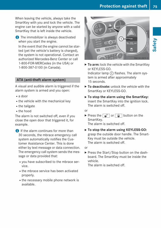
When leaving the vehicle, always take theSmartKey with you and lock the vehicle. Theengine can be started by anyone with a validSmartKey that is left inside the vehicle.
i The immobilizer is always deactivatedwhen you start the engine.In the event that the engine cannot be star-ted (yet the vehicle's battery is charged),the system is not operational. Contact anauthorized Mercedes-Benz Center or call1-800-FOR-MERCedes (in the USA) or1-800-387-0100 (in Canada).
ATA (anti-theft alarm system)A visual and audible alarm is triggered if thealarm system is armed and you open:Ra doorRthe vehicle with the mechanical keyRthe tailgateRthe hoodThe alarm is not switched off, even if youclose the open door that triggered it, forexample.
i If the alarm continues for more than30 seconds, the mbrace emergency callsystem automatically notifies the Cus-tomer Assistance Center. This is doneeither by text message or data connection.The emergency call system sends the mes-sage or data provided that:Ryou have subscribed to the mbrace ser-
vice.Rthe mbrace service has been activated
properly.Rthe necessary mobile phone network is
available.
X To arm: lock the vehicle with the SmartKeyor KEYLESS-GO.Indicator lamp : flashes. The alarm sys-tem is armed after approximately15 seconds.
X To deactivate: unlock the vehicle with theSmartKey or KEYLESS-GO.
X To stop the alarm using the SmartKey:insert the SmartKey into the ignition lock.The alarm is switched off.
orX Press the % or & button on the
SmartKey.The alarm is switched off.
X To stop the alarm using KEYLESS-GO:grasp the outside door handle. The Smart-Key must be outside the vehicle.The alarm is switched off.
orX Press the Start/Stop button on the dash-
board. The SmartKey must be inside thevehicle.The alarm is switched off.
Protection against theft 75
Safe
ty
Z

76

Useful information .............................. 78SmartKey ............................................. 78Doors .................................................... 84Cargo compartment ............................ 87Side windows ...................................... 91Sliding sunroof .................................... 95
77
Open
ing
and
clos
ing
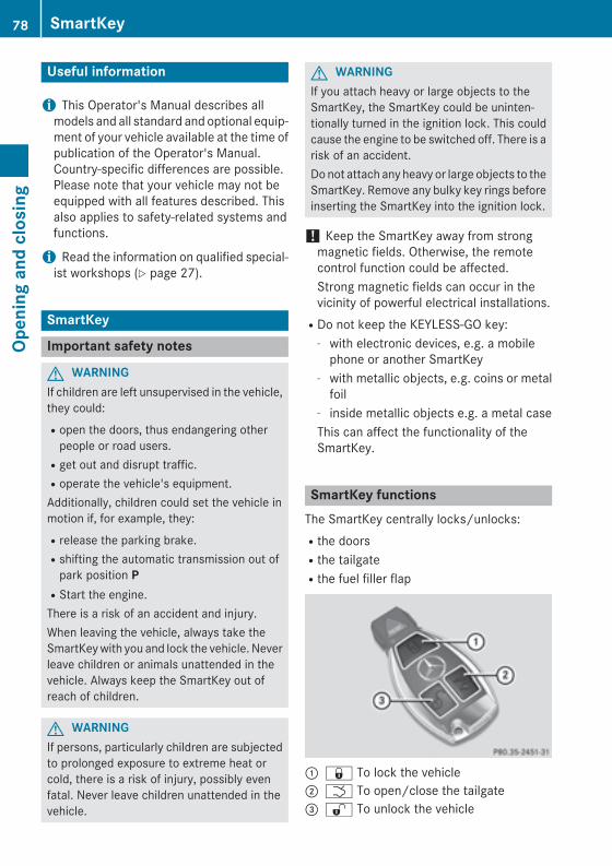
Useful information
i This Operator's Manual describes allmodels and all standard and optional equip-ment of your vehicle available at the time ofpublication of the Operator's Manual.Country-specific differences are possible.Please note that your vehicle may not beequipped with all features described. Thisalso applies to safety-related systems andfunctions.
i Read the information on qualified special-ist workshops (Y page 27).
SmartKey
Important safety notes
G WARNINGIf children are left unsupervised in the vehicle,they could:Ropen the doors, thus endangering other
people or road users.Rget out and disrupt traffic.Roperate the vehicle's equipment.Additionally, children could set the vehicle inmotion if, for example, they:Rrelease the parking brake.Rshifting the automatic transmission out of
park position PRStart the engine.There is a risk of an accident and injury.When leaving the vehicle, always take theSmartKey with you and lock the vehicle. Neverleave children or animals unattended in thevehicle. Always keep the SmartKey out ofreach of children.
G WARNINGIf persons, particularly children are subjectedto prolonged exposure to extreme heat orcold, there is a risk of injury, possibly evenfatal. Never leave children unattended in thevehicle.
G WARNINGIf you attach heavy or large objects to theSmartKey, the SmartKey could be uninten-tionally turned in the ignition lock. This couldcause the engine to be switched off. There is arisk of an accident.Do not attach any heavy or large objects to theSmartKey. Remove any bulky key rings beforeinserting the SmartKey into the ignition lock.
! Keep the SmartKey away from strongmagnetic fields. Otherwise, the remotecontrol function could be affected.Strong magnetic fields can occur in thevicinity of powerful electrical installations.RDo not keep the KEYLESS-GO key:
- with electronic devices, e.g. a mobilephone or another SmartKey
- with metallic objects, e.g. coins or metalfoil
- inside metallic objects e.g. a metal caseThis can affect the functionality of theSmartKey.
SmartKey functionsThe SmartKey centrally locks/unlocks:Rthe doorsRthe tailgateRthe fuel filler flap
: & To lock the vehicle; F To open/close the tailgate= % To unlock the vehicle
78 SmartKeyOp
enin
g an
d cl
osin
g
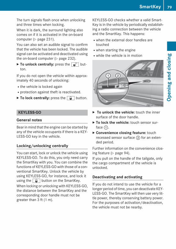
The turn signals flash once when unlockingand three times when locking.When it is dark, the surround lighting alsocomes on if it is activated in the on-boardcomputer (Y page 231).You can also set an audible signal to confirmthat the vehicle has been locked. The audiblesignal can be activated and deactivated usingthe on-board computer (Y page 232).X To unlock centrally: press the % but-
ton.
If you do not open the vehicle within approx-imately 40 seconds of unlocking:Rthe vehicle is locked againRprotection against theft is reactivated.X To lock centrally: press the & button.
KEYLESS-GO
General notesBear in mind that the engine can be started byany of the vehicle occupants if there is a KEY-LESS-GO key in the vehicle.
Locking/unlocking centrallyYou can start, lock or unlock the vehicle usingKEYLESS-GO. To do this, you only need carrythe SmartKey with you. You can combine thefunctions of KEYLESS-GO with those of a con-ventional SmartKey. Unlock the vehicle byusing KEYLESS-GO, for instance, and lock itusing the & button on the SmartKey.When locking or unlocking with KEYLESS-GO,the distance between the SmartKey and thecorresponding door handle must not begreater than 3 ft (1 m).
KEYLESS-GO checks whether a valid Smart-Key is in the vehicle by periodically establish-ing a radio connection between the vehicleand the SmartKey. This happens:Rwhen the external door handles are
touchedRwhen starting the engineRwhile the vehicle is in motion
X To unlock the vehicle: touch the innersurface of the door handle.
X To lock the vehicle: touch sensor sur-face :.
X Convenience closing feature: touchrecessed sensor surface ; for an exten-ded period.
Further information on the convenience clos-ing feature (Y page 94).If you pull on the handle of the tailgate, onlythe cargo compartment of the vehicle isunlocked.
Deactivating and activatingIf you do not intend to use the vehicle for alonger period of time, you can deactivate KEY-LESS-GO. The SmartKey will then use very lit-tle power, thereby conserving battery power.For the purposes of activation/deactivation,the vehicle must not be nearby.
SmartKey 79
Open
ing
and
clos
ing
Z
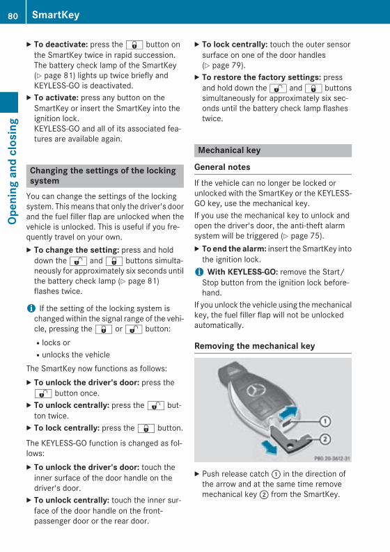
X To deactivate: press the & button onthe SmartKey twice in rapid succession.The battery check lamp of the SmartKey(Y page 81) lights up twice briefly andKEYLESS-GO is deactivated.
X To activate: press any button on theSmartKey or insert the SmartKey into theignition lock.KEYLESS-GO and all of its associated fea-tures are available again.
Changing the settings of the lockingsystem
You can change the settings of the lockingsystem. This means that only the driver's doorand the fuel filler flap are unlocked when thevehicle is unlocked. This is useful if you fre-quently travel on your own.X To change the setting: press and hold
down the % and & buttons simulta-neously for approximately six seconds untilthe battery check lamp (Y page 81)flashes twice.
i If the setting of the locking system ischanged within the signal range of the vehi-cle, pressing the & or % button:Rlocks orRunlocks the vehicle
The SmartKey now functions as follows:X To unlock the driver's door: press the% button once.
X To unlock centrally: press the % but-ton twice.
X To lock centrally: press the & button.
The KEYLESS-GO function is changed as fol-lows:X To unlock the driver's door: touch the
inner surface of the door handle on thedriver's door.
X To unlock centrally: touch the inner sur-face of the door handle on the front-passenger door or the rear door.
X To lock centrally: touch the outer sensorsurface on one of the door handles(Y page 79).
X To restore the factory settings: pressand hold down the % and & buttonssimultaneously for approximately six sec-onds until the battery check lamp flashestwice.
Mechanical key
General notesIf the vehicle can no longer be locked orunlocked with the SmartKey or the KEYLESS-GO key, use the mechanical key.If you use the mechanical key to unlock andopen the driver's door, the anti-theft alarmsystem will be triggered (Y page 75).X To end the alarm: insert the SmartKey into
the ignition lock.i With KEYLESS-GO: remove the Start/
Stop button from the ignition lock before-hand.
If you unlock the vehicle using the mechanicalkey, the fuel filler flap will not be unlockedautomatically.
Removing the mechanical key
X Push release catch : in the direction ofthe arrow and at the same time removemechanical key ; from the SmartKey.
80 SmartKeyOp
enin
g an
d cl
osin
g
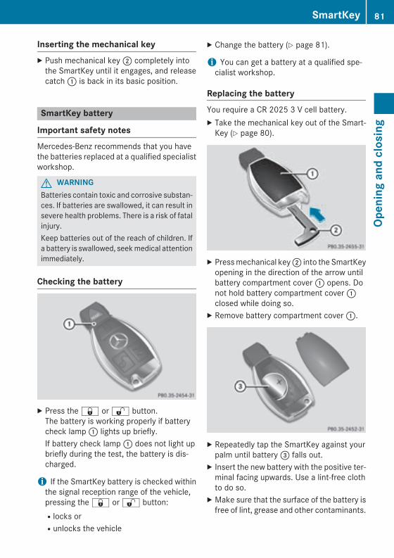
Inserting the mechanical keyX Push mechanical key ; completely into
the SmartKey until it engages, and releasecatch : is back in its basic position.
SmartKey battery
Important safety notesMercedes-Benz recommends that you havethe batteries replaced at a qualified specialistworkshop.
G WARNINGBatteries contain toxic and corrosive substan-ces. If batteries are swallowed, it can result insevere health problems. There is a risk of fatalinjury.Keep batteries out of the reach of children. Ifa battery is swallowed, seek medical attentionimmediately.
Checking the battery
X Press the & or % button.The battery is working properly if batterycheck lamp : lights up briefly.If battery check lamp : does not light upbriefly during the test, the battery is dis-charged.
i If the SmartKey battery is checked withinthe signal reception range of the vehicle,pressing the & or % button:Rlocks orRunlocks the vehicle
X Change the battery (Y page 81).
i You can get a battery at a qualified spe-cialist workshop.
Replacing the batteryYou require a CR 2025 3 V cell battery.X Take the mechanical key out of the Smart-
Key (Y page 80).
X Press mechanical key ; into the SmartKeyopening in the direction of the arrow untilbattery compartment cover : opens. Donot hold battery compartment cover :closed while doing so.
X Remove battery compartment cover :.
X Repeatedly tap the SmartKey against yourpalm until battery = falls out.
X Insert the new battery with the positive ter-minal facing upwards. Use a lint-free clothto do so.
X Make sure that the surface of the battery isfree of lint, grease and other contaminants.
SmartKey 81
Open
ing
and
clos
ing
Z
X Insert the front tabs of battery compart-ment cover : into the housing first andthen press to close it.
X Insert mechanical key ; into the Smart-Key (Y page 80).
X Check the function of all SmartKey buttonson the vehicle.
82 SmartKeyOp
enin
g an
d cl
osin
g
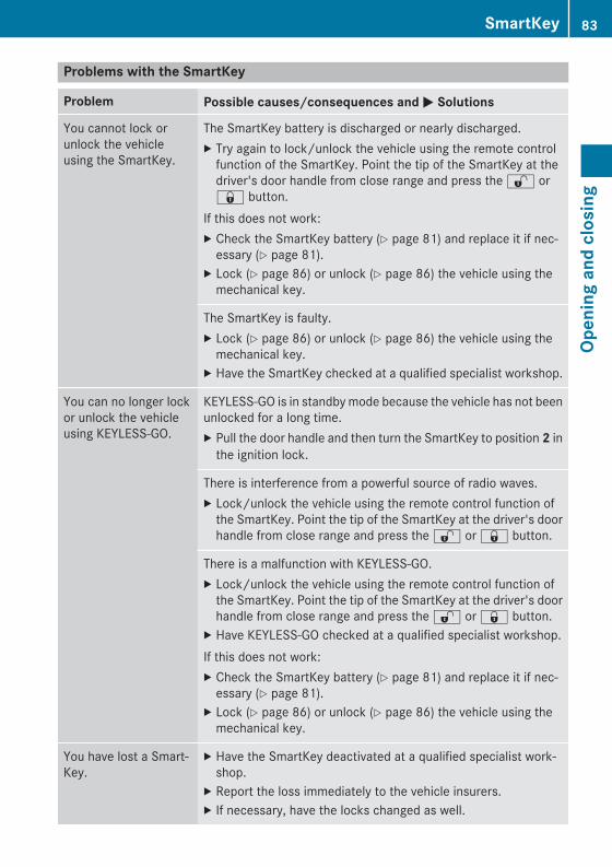
Problems with the SmartKey
Problem Possible causes/consequences and M Solutions
You cannot lock orunlock the vehicleusing the SmartKey.
The SmartKey battery is discharged or nearly discharged.X Try again to lock/unlock the vehicle using the remote control
function of the SmartKey. Point the tip of the SmartKey at thedriver's door handle from close range and press the % or& button.
If this does not work:X Check the SmartKey battery (Y page 81) and replace it if nec-
essary (Y page 81).X Lock (Y page 86) or unlock (Y page 86) the vehicle using the
mechanical key.
The SmartKey is faulty.X Lock (Y page 86) or unlock (Y page 86) the vehicle using the
mechanical key.X Have the SmartKey checked at a qualified specialist workshop.
You can no longer lockor unlock the vehicleusing KEYLESS-GO.
KEYLESS-GO is in standby mode because the vehicle has not beenunlocked for a long time.X Pull the door handle and then turn the SmartKey to position 2 in
the ignition lock.
There is interference from a powerful source of radio waves.X Lock/unlock the vehicle using the remote control function of
the SmartKey. Point the tip of the SmartKey at the driver's doorhandle from close range and press the % or & button.
There is a malfunction with KEYLESS-GO.X Lock/unlock the vehicle using the remote control function of
the SmartKey. Point the tip of the SmartKey at the driver's doorhandle from close range and press the % or & button.
X Have KEYLESS-GO checked at a qualified specialist workshop.If this does not work:X Check the SmartKey battery (Y page 81) and replace it if nec-
essary (Y page 81).X Lock (Y page 86) or unlock (Y page 86) the vehicle using the
mechanical key.
You have lost a Smart-Key.
X Have the SmartKey deactivated at a qualified specialist work-shop.
X Report the loss immediately to the vehicle insurers.X If necessary, have the locks changed as well.
SmartKey 83
Open
ing
and
clos
ing
Z
Problem Possible causes/consequences and M Solutions
You have lost themechanical key.
X Report the loss immediately to the vehicle insurers.X If necessary, have the locks changed as well.
The engine cannot bestarted using theSmartKey.
The on-board voltage is too low.X Switch off non-essential consumers, e.g. seat heating or interior
lighting, and try to start the engine again.If this does not work:X Check the starter battery and charge it if necessary
(Y page 319).orX Jump-start the vehicle (Y page 323).orX Consult a qualified specialist workshop.
The engine cannot bestarted using KEYLESS-GO. The SmartKey is inthe vehicle.
A door is open. Therefore, the SmartKey cannot be detected aseasily.X Close the door and try to start the vehicle again.
There is interference from a powerful source of radio waves.X Start your vehicle with the SmartKey in the ignition lock.
Doors
Important safety notes
G WARNINGIf children are left unsupervised in the vehicle,they could:Ropen the doors, thus endangering other
people or road users.Rget out and disrupt traffic.Roperate the vehicle's equipment.Additionally, children could set the vehicle inmotion if, for example, they:Rrelease the parking brake.Rshifting the automatic transmission out of
park position PRStart the engine.There is a risk of an accident and injury.When leaving the vehicle, always take theSmartKey with you and lock the vehicle. Never
leave children or animals unattended in thevehicle. Always keep the SmartKey out ofreach of children.
G WARNINGIf persons, particularly children are subjectedto prolonged exposure to extreme heat orcold, there is a risk of injury, possibly evenfatal. Never leave children unattended in thevehicle.
You should preferably place luggage or loadsin the cargo compartment. Observe the load-ing guidelines (Y page 274).
Unlocking and opening doors fromthe inside
You can open a door from inside the vehicleeven if it has been locked. You can only openthe rear doors from inside the vehicle if they
84 DoorsOp
enin
g an
d cl
osin
g

are not secured by the child-proof locks(Y page 67).You can open a door from inside the vehicleeven if it has been locked.Only open the door when the traffic situationpermits.If the vehicle has been locked with the Smart-Key or with KEYLESS-GO, opening a door fromthe inside will trigger the anti-theft alarm sys-tem. Switch off the alarm (Y page 75).
X To unlock a front door: pull door han-dle ;.Locking knob : pops up.The door is unlocked and can be opened.
X To open a front door: pull door handle ;.
X To unlock a rear door: pull up lockingknob :.The door is unlocked and can be opened.
X To open a rear door: pull door handle ;.
Centrally locking and unlocking thevehicle from the inside
You can centrally lock or unlock the vehiclefrom the inside.You cannot unlock the vehicle centrally fromthe inside if the vehicle has been locked withthe SmartKey or KEYLESS-GO.
X To unlock: press button :.X To lock: press button ;.
If the front-passenger door is closed, thevehicle locks.
Meanwhile, the fuel filler flap will not belocked or unlocked.You can open a door from inside the vehicleeven if it has been locked.Only open the door when the traffic situationpermits.If the vehicle was previously locked with theSmartKey or with KEYLESS-GO, opening thevehicle from the inside will activate the anti-theft alarm system. Switch off the alarm(Y page 75).If a locked door is opened from the inside, theprevious unlock status of the vehicle will betaken into consideration if:Rthe vehicle was locked using the locking
button for the central locking, orRif the vehicle was locked automaticallyThe vehicle will be fully unlocked if it had pre-viously been fully unlocked. If only the driver'sdoor had been previously unlocked, only thedoor which has been opened from the insideis unlocked.If the vehicle has been locked centrally withthe SmartKey or with KEYLESS-GO, it is notunlocked when the release button for thecentral locking is used.
Doors 85
Open
ing
and
clos
ing
Z
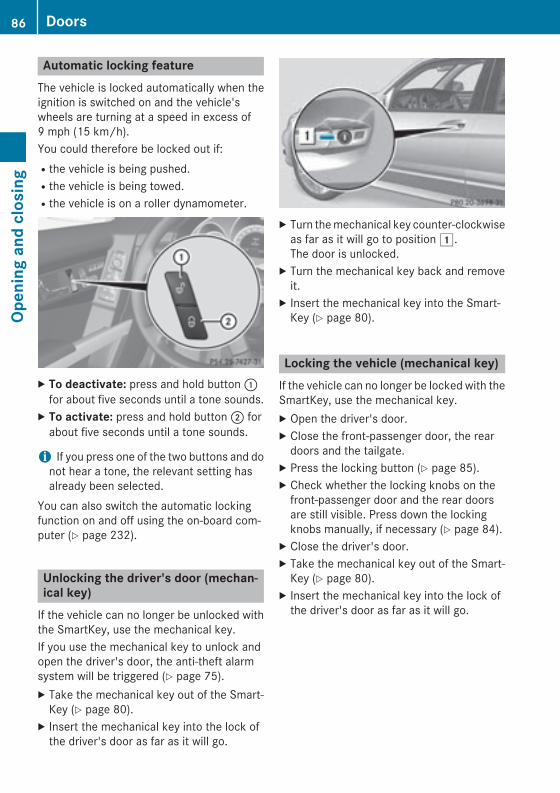
Automatic locking featureThe vehicle is locked automatically when theignition is switched on and the vehicle'swheels are turning at a speed in excess of9 mph (15 km/h).You could therefore be locked out if:Rthe vehicle is being pushed.Rthe vehicle is being towed.Rthe vehicle is on a roller dynamometer.
X To deactivate: press and hold button :for about five seconds until a tone sounds.
X To activate: press and hold button ; forabout five seconds until a tone sounds.
i If you press one of the two buttons and donot hear a tone, the relevant setting hasalready been selected.
You can also switch the automatic lockingfunction on and off using the on-board com-puter (Y page 232).
Unlocking the driver's door (mechan-ical key)
If the vehicle can no longer be unlocked withthe SmartKey, use the mechanical key.If you use the mechanical key to unlock andopen the driver's door, the anti-theft alarmsystem will be triggered (Y page 75).X Take the mechanical key out of the Smart-
Key (Y page 80).X Insert the mechanical key into the lock of
the driver's door as far as it will go.
X Turn the mechanical key counter-clockwiseas far as it will go to position 1.The door is unlocked.
X Turn the mechanical key back and removeit.
X Insert the mechanical key into the Smart-Key (Y page 80).
Locking the vehicle (mechanical key)If the vehicle can no longer be locked with theSmartKey, use the mechanical key.X Open the driver's door.X Close the front-passenger door, the rear
doors and the tailgate.X Press the locking button (Y page 85).X Check whether the locking knobs on the
front-passenger door and the rear doorsare still visible. Press down the lockingknobs manually, if necessary (Y page 84).
X Close the driver's door.X Take the mechanical key out of the Smart-
Key (Y page 80).X Insert the mechanical key into the lock of
the driver's door as far as it will go.
86 DoorsOp
enin
g an
d cl
osin
g
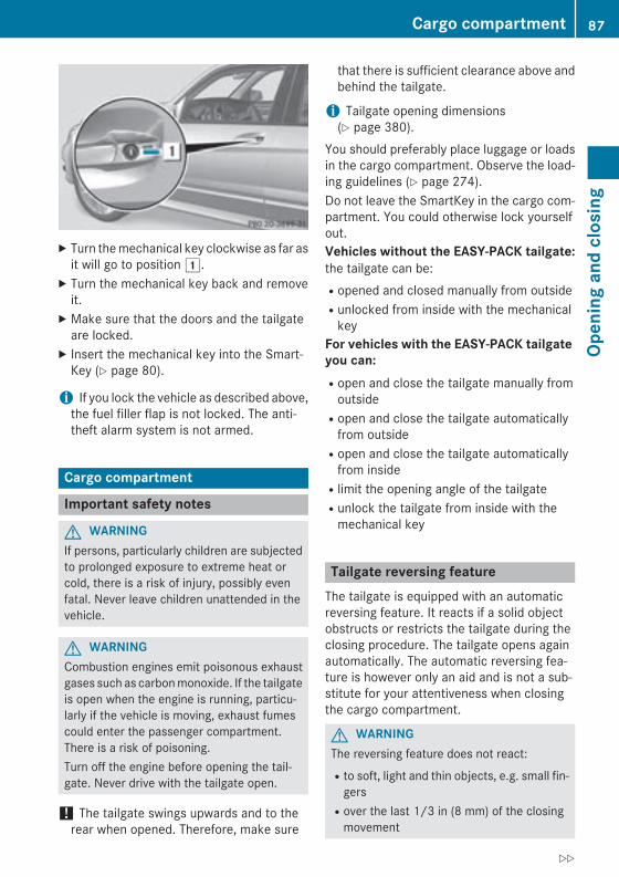
X Turn the mechanical key clockwise as far asit will go to position 1.
X Turn the mechanical key back and removeit.
X Make sure that the doors and the tailgateare locked.
X Insert the mechanical key into the Smart-Key (Y page 80).
i If you lock the vehicle as described above,the fuel filler flap is not locked. The anti-theft alarm system is not armed.
Cargo compartment
Important safety notes
G WARNINGIf persons, particularly children are subjectedto prolonged exposure to extreme heat orcold, there is a risk of injury, possibly evenfatal. Never leave children unattended in thevehicle.
G WARNINGCombustion engines emit poisonous exhaustgases such as carbon monoxide. If the tailgateis open when the engine is running, particu-larly if the vehicle is moving, exhaust fumescould enter the passenger compartment.There is a risk of poisoning.Turn off the engine before opening the tail-gate. Never drive with the tailgate open.
! The tailgate swings upwards and to therear when opened. Therefore, make sure
that there is sufficient clearance above andbehind the tailgate.
i Tailgate opening dimensions(Y page 380).
You should preferably place luggage or loadsin the cargo compartment. Observe the load-ing guidelines (Y page 274).Do not leave the SmartKey in the cargo com-partment. You could otherwise lock yourselfout.Vehicles without the EASY-PACK tailgate:the tailgate can be:Ropened and closed manually from outsideRunlocked from inside with the mechanical
keyFor vehicles with the EASY-PACK tailgate you can:Ropen and close the tailgate manually from
outsideRopen and close the tailgate automatically
from outsideRopen and close the tailgate automatically
from insideRlimit the opening angle of the tailgateRunlock the tailgate from inside with the
mechanical key
Tailgate reversing featureThe tailgate is equipped with an automaticreversing feature. It reacts if a solid objectobstructs or restricts the tailgate during theclosing procedure. The tailgate opens againautomatically. The automatic reversing fea-ture is however only an aid and is not a sub-stitute for your attentiveness when closingthe cargo compartment.
G WARNINGThe reversing feature does not react:Rto soft, light and thin objects, e.g. small fin-
gersRover the last 1/3 in (8 mm) of the closing
movement
Cargo compartment 87
Open
ing
and
clos
ing
Z
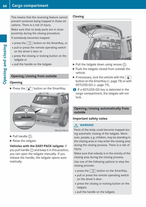
This means that the reversing feature cannotprevent someone being trapped in these sit-uations. There is a risk of injury.Make sure that no body parts are in closeproximity during the closing procedure.If somebody becomes trapped:Rpress the F button on the SmartKey, orRpull or press the remote operating switch
on the driver's door orRpress the closing or locking button on the
tailgate orRpull the handle on the tailgate
Opening/closing from outside
OpeningX Press the % button on the SmartKey.
X Pull handle :.X Raise the tailgate.Vehicles with the EASY-PACK tailgate: ifyou pull handle : and keep it in this position,you can open the tailgate manually. If yourelease the handle, the tailgate opens auto-matically.
Closing
X Pull the tailgate down using recess :.X Push the tailgate closed from outside the
vehicle.X If necessary, lock the vehicle with the &
button on the SmartKey (Y page 78) or withKEYLESS-GO (Y page 79).
i If a KEYLESS-GO key is detected in thecargo compartment, the tailgate will notlock.
Opening/closing automatically fromoutside
Important safety notes
G WARNINGParts of the body could become trapped dur-ing automatic closing of the tailgate. More-over, people, e.g. children, may be standing inthe closing area or may enter the closing areaduring the closing process. There is a risk ofinjury.Make sure that nobody is in the vicinity of theclosing area during the closing process.Use one of the following options to stop theclosing process:Rpress the F button on the SmartKey.Rpull or press the remote operating switch
on the driver's door.Rpress the closing or locking button on the
tailgate.Rpull the handle on the tailgate.
88 Cargo compartmentOp
enin
g an
d cl
osin
g
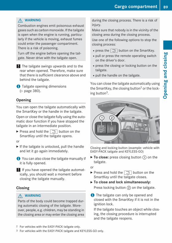
G WARNINGCombustion engines emit poisonous exhaustgases such as carbon monoxide. If the tailgateis open when the engine is running, particu-larly if the vehicle is moving, exhaust fumescould enter the passenger compartment.There is a risk of poisoning.Turn off the engine before opening the tail-gate. Never drive with the tailgate open.
! The tailgate swings upwards and to therear when opened. Therefore, make surethat there is sufficient clearance above andbehind the tailgate.
i Tailgate opening dimensions(Y page 380).
OpeningYou can open the tailgate automatically withthe SmartKey or the handle in the tailgate.Open or close the tailgate fully using the auto-matic door function if you have stopped thetailgate in an intermediate position.X Press and hold the F button on the
SmartKey until the tailgate opens.orX If the tailgate is unlocked, pull the handle
and let it go again immediately.
i You can also close the tailgate manually ifit is fully opened.
! If you have opened the tailgate automat-ically, you should wait a moment beforeclosing the tailgate manually.
Closing
G WARNINGParts of the body could become trapped dur-ing automatic closing of the tailgate. More-over, people, e.g. children, may be standing inthe closing area or may enter the closing area
during the closing process. There is a risk ofinjury.Make sure that nobody is in the vicinity of theclosing area during the closing process.Use one of the following options to stop theclosing process:Rpress the F button on the SmartKey.Rpull or press the remote operating switch
on the driver's door.Rpress the closing or locking button on the
tailgate.Rpull the handle on the tailgate.
You can close the tailgate automatically usingthe SmartKey, the closing button2 or the lock-ing button3.
Closing and locking button (example: vehicle withEASY-PACK tailgate and KEYLESS-GO)X To close: press closing button : on the
tailgate.orX Press and hold the F button on the
SmartKey until the tailgate closes.X To close and lock simultaneously:
Press locking button ; on the tailgate.
i The tailgate can only be opened andclosed with the SmartKey if it is not in theignition lock.If the tailgate touches an object while clos-ing, the closing procedure is interruptedand the tailgate reopens.
2 For vehicles with the EASY-PACK tailgate only.3 For vehicles with the EASY-PACK tailgate and KEYLESS-GO only.
Cargo compartment 89
Open
ing
and
clos
ing
Z
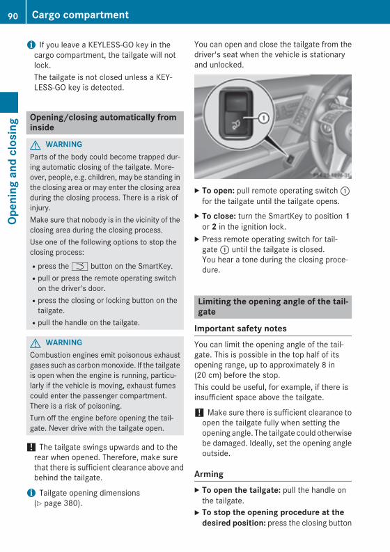
i If you leave a KEYLESS-GO key in thecargo compartment, the tailgate will notlock.The tailgate is not closed unless a KEY-LESS-GO key is detected.
Opening/closing automatically frominside
G WARNINGParts of the body could become trapped dur-ing automatic closing of the tailgate. More-over, people, e.g. children, may be standing inthe closing area or may enter the closing areaduring the closing process. There is a risk ofinjury.Make sure that nobody is in the vicinity of theclosing area during the closing process.Use one of the following options to stop theclosing process:Rpress the F button on the SmartKey.Rpull or press the remote operating switch
on the driver's door.Rpress the closing or locking button on the
tailgate.Rpull the handle on the tailgate.
G WARNINGCombustion engines emit poisonous exhaustgases such as carbon monoxide. If the tailgateis open when the engine is running, particu-larly if the vehicle is moving, exhaust fumescould enter the passenger compartment.There is a risk of poisoning.Turn off the engine before opening the tail-gate. Never drive with the tailgate open.
! The tailgate swings upwards and to therear when opened. Therefore, make surethat there is sufficient clearance above andbehind the tailgate.
i Tailgate opening dimensions(Y page 380).
You can open and close the tailgate from thedriver's seat when the vehicle is stationaryand unlocked.
X To open: pull remote operating switch :for the tailgate until the tailgate opens.
X To close: turn the SmartKey to position 1or 2 in the ignition lock.
X Press remote operating switch for tail-gate : until the tailgate is closed.You hear a tone during the closing proce-dure.
Limiting the opening angle of the tail-gate
Important safety notesYou can limit the opening angle of the tail-gate. This is possible in the top half of itsopening range, up to approximately 8 in(20 cm) before the stop.This could be useful, for example, if there isinsufficient space above the tailgate.
! Make sure there is sufficient clearance toopen the tailgate fully when setting theopening angle. The tailgate could otherwisebe damaged. Ideally, set the opening angleoutside.
ArmingX To open the tailgate: pull the handle on
the tailgate.X To stop the opening procedure at the
desired position: press the closing button
90 Cargo compartmentOp
enin
g an
d cl
osin
g

(Y page 88) in the tailgate or pull the handleon the outside of the tailgate again.
X To store the position: press and hold theclosing button in the tailgate until you heara short tone.The opening angle limiter is activated. Thetailgate will now stop in the stored positionwhen opening.
i To open the tailgate fully, pull the handleon the outside of the tailgate again after ithas stopped automatically. This does notdelete the stored position.
DeactivatingX Press and hold the closing button
(Y page 88) in the tailgate until you heartwo short tones.
Tailgate emergency release
Important safety notes
! The tailgate swings upwards and to therear when opened. Therefore, make surethat there is sufficient clearance above andbehind the tailgate.
If the tailgate can no longer be opened fromoutside the vehicle, use the emergencyrelease on the inside of the tailgate.
i Tailgate opening dimensions(Y page 380).
Opening
X Take the mechanical key out of the Smart-Key (Y page 80).
X Insert mechanical key ; into the openingin paneling :.
X Turn mechanical key ; 90° clockwise.X Push mechanical key ; in the direction of
the arrow and open the tailgate.X Insert mechanical key ; into the Smart-
Key (Y page 80).
i When you lock the vehicle (Y page 86),the cargo compartment is also locked.
Side windows
Important safety notes
G WARNINGWhile opening the side windows, body partscould become trapped between the side win-dow and the door frame as the side windowmoves. There is a risk of injury.Make sure that nobody touches the side win-dow during the opening procedure. If some-body becomes trapped, release the switch orpull the switch to close the side window again.
G WARNINGWhile opening the side windows, body parts inthe closing area could become trapped. Thereis a risk of injury.Make sure that no body parts are in closeproximity during the closing procedure. Ifsomebody becomes trapped, release theswitch or press the switch down to open theside window again.
G WARNINGIf children operate the side windows theycould become trapped, particularly if they areleft unsupervised. There is a risk of injury.Activate the override feature for the rear sidewindows. When leaving the vehicle, alwaystake the SmartKey with you and lock the vehi-cle. Never leave children unsupervised in thevehicle.
Side windows 91
Open
ing
and
clos
ing
Z
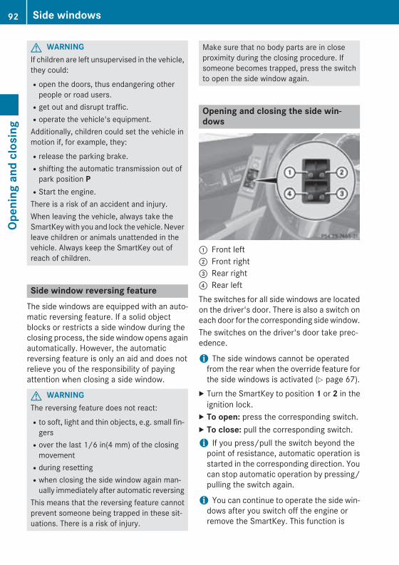
G WARNINGIf children are left unsupervised in the vehicle,they could:Ropen the doors, thus endangering other
people or road users.Rget out and disrupt traffic.Roperate the vehicle's equipment.Additionally, children could set the vehicle inmotion if, for example, they:Rrelease the parking brake.Rshifting the automatic transmission out of
park position PRStart the engine.There is a risk of an accident and injury.When leaving the vehicle, always take theSmartKey with you and lock the vehicle. Neverleave children or animals unattended in thevehicle. Always keep the SmartKey out ofreach of children.
Side window reversing featureThe side windows are equipped with an auto-matic reversing feature. If a solid objectblocks or restricts a side window during theclosing process, the side window opens againautomatically. However, the automaticreversing feature is only an aid and does notrelieve you of the responsibility of payingattention when closing a side window.
G WARNINGThe reversing feature does not react:Rto soft, light and thin objects, e.g. small fin-
gersRover the last 1/6 in(4 mm) of the closing
movementRduring resettingRwhen closing the side window again man-
ually immediately after automatic reversingThis means that the reversing feature cannotprevent someone being trapped in these sit-uations. There is a risk of injury.
Make sure that no body parts are in closeproximity during the closing procedure. Ifsomeone becomes trapped, press the switchto open the side window again.
Opening and closing the side win-dows
: Front left; Front right= Rear right? Rear leftThe switches for all side windows are locatedon the driver's door. There is also a switch oneach door for the corresponding side window.The switches on the driver's door take prec-edence.
i The side windows cannot be operatedfrom the rear when the override feature forthe side windows is activated (Y page 67).
X Turn the SmartKey to position 1 or 2 in theignition lock.
X To open: press the corresponding switch.X To close: pull the corresponding switch.i If you press/pull the switch beyond the
point of resistance, automatic operation isstarted in the corresponding direction. Youcan stop automatic operation by pressing/pulling the switch again.
i You can continue to operate the side win-dows after you switch off the engine orremove the SmartKey. This function is
92 Side windowsOp
enin
g an
d cl
osin
g
available for up to five minutes or until thedriver's or front-passenger door is opened.
Convenience openingYou can ventilate the vehicle before you startdriving. To do this, the SmartKey is used tocarry out the following functions simultane-ously:Runlock the vehicleRopen the side windowsRopen the panorama roof with power tilt/
sliding panel and the roller sunblinds
i The convenience opening feature canonly be operated using the SmartKey. TheSmartKey must be close to the driver'sdoor handle.
X Point the tip of the SmartKey at the driver'sdoor handle.
X Press and hold the % button until theside windows and the panorama roof withpower tilt/sliding panel are in the desiredposition.
If the roller sunblinds of the panorama roofwith power tilt/sliding panel are closed, theroller sunblinds are opened first.X Press and hold the % button again until
the panorama roof with power tilt/slidingpanel is in the desired position.
X To interrupt convenience opening:release the % button.
Convenience closing feature
General notesWhen you lock the vehicle, you can simulta-neously:Rclose the side windowsRclose the panorama roof with power tilt/
sliding panelOn vehicles with a panorama roof with powertilt/sliding panel, you can then close theroller sunblinds.
G WARNINGWhen the convenience closing feature is oper-ating, parts of the body could become trappedin the closing area of the side window and thesliding sunroof. There is a risk of injury.Observe the complete closing procedurewhen the convenience closing feature is oper-ating. Make sure that no body parts are inclose proximity during the closing procedure.
Proceed as follows if someone is trapped:With the SmartKey:Rrelease the & button.Rpress and hold the % button until the
side windows and the sliding sunroof or thepanorama roof with power tilt/slidingpanel open again.
Using KEYLESS-GO:Rrelease the sensor surface on the door han-
dle.Rpull the door handle immediately and hold
it.The side windows and the sliding sunroof orthe panorama roof with power tilt/slidingpanel open.
Using the SmartKey
i The SmartKey must be close to the driv-er's door handle.
X Point the tip of the SmartKey at the driver'sdoor handle.
X Press and hold the & button until theside windows and the panorama roof withpower tilt/sliding panel are fully closed.
X Make sure that all the side windows and thepanorama roof with power tilt/slidingpanel are closed.
On vehicles with a panorama roof with powertilt/sliding panel:X Press and hold the & button again until
the roller sunblinds of the panorama roofwith power tilt/sliding panel close.
Side windows 93
Open
ing
and
clos
ing
Z
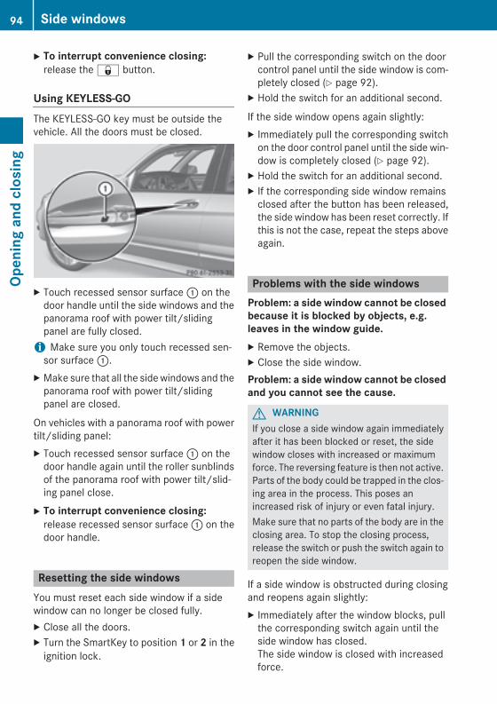
X To interrupt convenience closing:release the & button.
Using KEYLESS-GOThe KEYLESS-GO key must be outside thevehicle. All the doors must be closed.
X Touch recessed sensor surface : on thedoor handle until the side windows and thepanorama roof with power tilt/slidingpanel are fully closed.
i Make sure you only touch recessed sen-sor surface :.
X Make sure that all the side windows and thepanorama roof with power tilt/slidingpanel are closed.
On vehicles with a panorama roof with powertilt/sliding panel:X Touch recessed sensor surface : on the
door handle again until the roller sunblindsof the panorama roof with power tilt/slid-ing panel close.
X To interrupt convenience closing: release recessed sensor surface : on thedoor handle.
Resetting the side windowsYou must reset each side window if a sidewindow can no longer be closed fully.X Close all the doors.X Turn the SmartKey to position 1 or 2 in the
ignition lock.
X Pull the corresponding switch on the doorcontrol panel until the side window is com-pletely closed (Y page 92).
X Hold the switch for an additional second.
If the side window opens again slightly:X Immediately pull the corresponding switch
on the door control panel until the side win-dow is completely closed (Y page 92).
X Hold the switch for an additional second.X If the corresponding side window remains
closed after the button has been released,the side window has been reset correctly. Ifthis is not the case, repeat the steps aboveagain.
Problems with the side windowsProblem: a side window cannot be closed because it is blocked by objects, e.g. leaves in the window guide.X Remove the objects.X Close the side window.Problem: a side window cannot be closed and you cannot see the cause.
G WARNINGIf you close a side window again immediatelyafter it has been blocked or reset, the sidewindow closes with increased or maximumforce. The reversing feature is then not active.Parts of the body could be trapped in the clos-ing area in the process. This poses anincreased risk of injury or even fatal injury.Make sure that no parts of the body are in theclosing area. To stop the closing process,release the switch or push the switch again toreopen the side window.
If a side window is obstructed during closingand reopens again slightly:X Immediately after the window blocks, pull
the corresponding switch again until theside window has closed.The side window is closed with increasedforce.
94 Side windowsOp
enin
g an
d cl
osin
g
If a side window is obstructed again duringclosing and reopens again slightly:X Immediately after the window blocks, pull
the corresponding switch again until theside window has closed.The side window is closed without the anti-entrapment feature.
Sliding sunroof
Important safety notesIn the following section, the term "sliding sun-roof" refers to the panorama roof with powertilt/sliding panel.
G WARNINGWhile opening and closing the sliding sunroof,body parts in close proximity could becometrapped. There is a risk of injury.Make sure that no body parts are in closeproximity during the opening and closing pro-cedures.If somebody becomes trapped:Rrelease the switch immediately, orRduring automatic operation, push the
switch briefly in any directionThe opening or closing procedure will be stop-ped.
G WARNINGIf children operate the sliding sunroof theycould become trapped, particularly if they areleft unsupervised. There is a risk of injury.When leaving the vehicle, always take theSmartKey with you and lock the vehicle. Neverleave children unsupervised in the vehicle.
! Only open the sliding sunroof if it is free ofsnow and ice. Otherwise, malfunctions mayoccur.Do not allow anything to protrude from thesliding sunroof. Otherwise, the seals couldbe damaged.
! The weather can change abruptly. It couldstart to rain or snow. Make sure that thesliding sunroof is closed when you leave thevehicle. The vehicle electronics can bedamaged if water enters the vehicle inte-rior.
i Resonance noises can occur in addition tothe usual airflow noises when the slidingsunroof is open. They are caused by minorpressure fluctuations in the vehicle interior.Change the position of the sliding sunroofor open a side window slightly to reduce oreliminate these noises.
Sliding sunroof reversing featureThe sliding sunroof is equipped with an auto-matic reversing feature. If a solid objectblocks or restricts the sliding sunroof duringthe closing process, the sliding sunroof opensagain automatically. However, the automaticreversing feature is only an aid and does notrelieve you of the responsibility of payingattention when closing the sliding sunroof.
G WARNINGThe reversing feature does not react:Rto soft, light and thin objects, e.g. small fin-
gersRover the last 1/6 in(4 mm) of the closing
movementRduring resettingRwhen closing the sliding sunroof again man-
ually immediately after automatic reversingThis means that the reversing feature cannotprevent someone being trapped in these sit-uations. There is a risk of injury.Make sure that no body parts are in closeproximity during the closing procedure.If somebody becomes trapped:Rrelease the switch immediately, orRduring automatic operation, push the
switch briefly in any directionThe closing process is stopped.
Sliding sunroof 95
Open
ing
and
clos
ing
Z
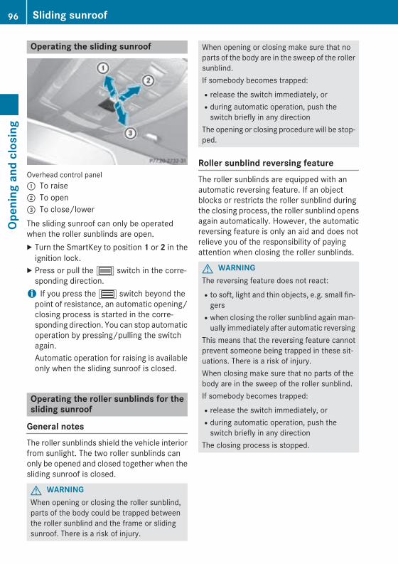
Operating the sliding sunroof
Overhead control panel: To raise; To open= To close/lowerThe sliding sunroof can only be operatedwhen the roller sunblinds are open.X Turn the SmartKey to position 1 or 2 in the
ignition lock.X Press or pull the 3 switch in the corre-
sponding direction.i If you press the 3 switch beyond the
point of resistance, an automatic opening/closing process is started in the corre-sponding direction. You can stop automaticoperation by pressing/pulling the switchagain.Automatic operation for raising is availableonly when the sliding sunroof is closed.
Operating the roller sunblinds for thesliding sunroof
General notesThe roller sunblinds shield the vehicle interiorfrom sunlight. The two roller sunblinds canonly be opened and closed together when thesliding sunroof is closed.
G WARNINGWhen opening or closing the roller sunblind,parts of the body could be trapped betweenthe roller sunblind and the frame or slidingsunroof. There is a risk of injury.
When opening or closing make sure that noparts of the body are in the sweep of the rollersunblind.If somebody becomes trapped:Rrelease the switch immediately, orRduring automatic operation, push the
switch briefly in any directionThe opening or closing procedure will be stop-ped.
Roller sunblind reversing featureThe roller sunblinds are equipped with anautomatic reversing feature. If an objectblocks or restricts the roller sunblind duringthe closing process, the roller sunblind opensagain automatically. However, the automaticreversing feature is only an aid and does notrelieve you of the responsibility of payingattention when closing the roller sunblinds.
G WARNINGThe reversing feature does not react:Rto soft, light and thin objects, e.g. small fin-
gersRwhen closing the roller sunblind again man-
ually immediately after automatic reversingThis means that the reversing feature cannotprevent someone being trapped in these sit-uations. There is a risk of injury.When closing make sure that no parts of thebody are in the sweep of the roller sunblind.If somebody becomes trapped:Rrelease the switch immediately, orRduring automatic operation, push the
switch briefly in any directionThe closing process is stopped.
96 Sliding sunroofOp
enin
g an
d cl
osin
g
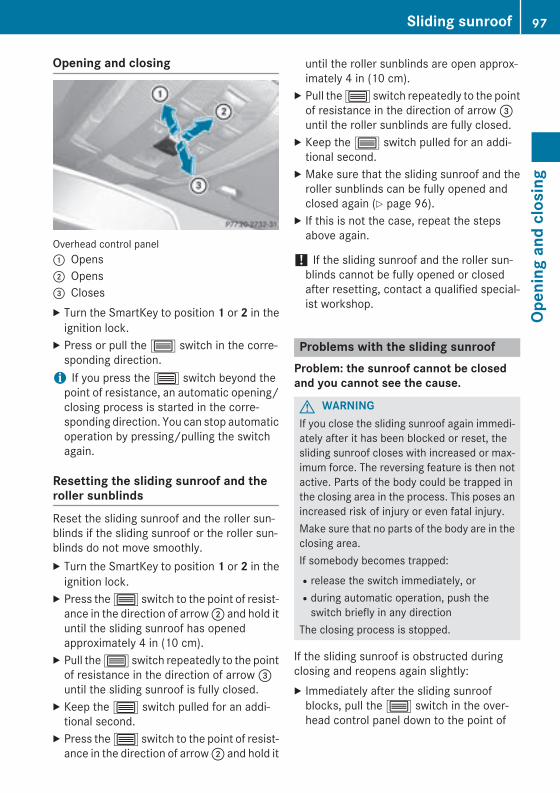
Opening and closing
Overhead control panel: Opens; Opens= ClosesX Turn the SmartKey to position 1 or 2 in the
ignition lock.X Press or pull the 3 switch in the corre-
sponding direction.i If you press the 3 switch beyond the
point of resistance, an automatic opening/closing process is started in the corre-sponding direction. You can stop automaticoperation by pressing/pulling the switchagain.
Resetting the sliding sunroof and theroller sunblindsReset the sliding sunroof and the roller sun-blinds if the sliding sunroof or the roller sun-blinds do not move smoothly.X Turn the SmartKey to position 1 or 2 in the
ignition lock.X Press the 3 switch to the point of resist-
ance in the direction of arrow ; and hold ituntil the sliding sunroof has openedapproximately 4 in (10 cm).
X Pull the 3 switch repeatedly to the pointof resistance in the direction of arrow =until the sliding sunroof is fully closed.
X Keep the 3 switch pulled for an addi-tional second.
X Press the 3 switch to the point of resist-ance in the direction of arrow ; and hold it
until the roller sunblinds are open approx-imately 4 in (10 cm).
X Pull the 3 switch repeatedly to the pointof resistance in the direction of arrow =until the roller sunblinds are fully closed.
X Keep the 3 switch pulled for an addi-tional second.
X Make sure that the sliding sunroof and theroller sunblinds can be fully opened andclosed again (Y page 96).
X If this is not the case, repeat the stepsabove again.
! If the sliding sunroof and the roller sun-blinds cannot be fully opened or closedafter resetting, contact a qualified special-ist workshop.
Problems with the sliding sunroofProblem: the sunroof cannot be closed and you cannot see the cause.
G WARNINGIf you close the sliding sunroof again immedi-ately after it has been blocked or reset, thesliding sunroof closes with increased or max-imum force. The reversing feature is then notactive. Parts of the body could be trapped inthe closing area in the process. This poses anincreased risk of injury or even fatal injury.Make sure that no parts of the body are in theclosing area.If somebody becomes trapped:Rrelease the switch immediately, orRduring automatic operation, push the
switch briefly in any directionThe closing process is stopped.
If the sliding sunroof is obstructed duringclosing and reopens again slightly:X Immediately after the sliding sunroof
blocks, pull the 3 switch in the over-head control panel down to the point of
Sliding sunroof 97
Open
ing
and
clos
ing
Z
resistance and hold it until the sliding sun-roof is closed.The sliding sunroof is closed with increasedforce.
If the sliding sunroof is obstructed again dur-ing closing and then reopens slightly:X Immediately after the sliding sunroof
blocks, pull the 3 switch in the over-head control panel down to the point ofresistance and hold it until the sliding sun-roof is closed.The sliding sunroof is closed without theanti-entrapment feature.
! If the sliding sunroof still cannot beopened or closed as a result of a malfunc-tion, contact a qualified specialist work-shop.
98 Sliding sunroofOp
enin
g an
d cl
osin
g
Useful information ............................ 100Correct driver's seat position .......... 100Seats .................................................. 101Steering wheel .................................. 106Mirrors ............................................... 109Memory function ............................... 112
99
Seat
s, s
teer
ing
whe
el a
nd m
irror
s
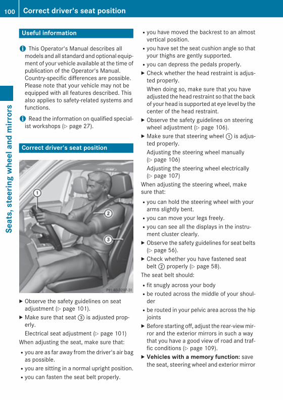
Useful information
i This Operator's Manual describes allmodels and all standard and optional equip-ment of your vehicle available at the time ofpublication of the Operator's Manual.Country-specific differences are possible.Please note that your vehicle may not beequipped with all features described. Thisalso applies to safety-related systems andfunctions.
i Read the information on qualified special-ist workshops (Y page 27).
Correct driver's seat position
X Observe the safety guidelines on seatadjustment (Y page 101).
X Make sure that seat = is adjusted prop-erly.Electrical seat adjustment (Y page 101)
When adjusting the seat, make sure that:Ryou are as far away from the driver's air bag
as possible.Ryou are sitting in a normal upright position.Ryou can fasten the seat belt properly.
Ryou have moved the backrest to an almostvertical position.Ryou have set the seat cushion angle so that
your thighs are gently supported.Ryou can depress the pedals properly.X Check whether the head restraint is adjus-
ted properly.When doing so, make sure that you haveadjusted the head restraint so that the backof your head is supported at eye level by thecenter of the head restraint.
X Observe the safety guidelines on steeringwheel adjustment (Y page 106).
X Make sure that steering wheel : is adjus-ted properly.Adjusting the steering wheel manually(Y page 106)Adjusting the steering wheel electrically(Y page 107)
When adjusting the steering wheel, makesure that:Ryou can hold the steering wheel with your
arms slightly bent.Ryou can move your legs freely.Ryou can see all the displays in the instru-
ment cluster clearly.X Observe the safety guidelines for seat belts
(Y page 56).X Check whether you have fastened seat
belt ; properly (Y page 58).The seat belt should:Rfit snugly across your bodyRbe routed across the middle of your shoul-
derRbe routed in your pelvic area across the hip
jointsX Before starting off, adjust the rear-view mir-
ror and the exterior mirrors in such a waythat you have a good view of road and traf-fic conditions (Y page 109).
X Vehicles with a memory function: savethe seat, steering wheel and exterior mirror
100 Correct driver's seat positionSe
ats,
ste
erin
g w
heel
and
mirr
ors

settings with the memory function(Y page 112).
Seats
Important safety notes
G WARNINGChildren could become trapped if they adjustthe seats, particularly when unattended.There is a risk of injury.When leaving the vehicle, always take theSmartKey with you and lock the vehicle. Neverleave children unsupervised in the vehicle.
The seats can still be adjusted when there isno SmartKey in the ignition lock.
G WARNINGYou could lose control of your vehicle if you dothe following while driving:Radjust the driver's seat, head restraint,
steering wheel or mirrorsRfasten the seat beltThere is a risk of an accident.Adjust the driver's seat, head restraint, steer-ing wheel and mirror and fasten your seat beltbefore starting the engine.
G WARNINGIf you adjust the seat height carelessly, you orother vehicle occupants could be trapped andthereby injured. Children in particular couldaccidentally press the electrical seat adjust-ment buttons and become trapped. There is arisk of injury.While moving the seats, make sure that yourhands or other body parts do not get under thelever assembly of the seat adjustment sys-tem.
G WARNINGWhen you adjust a seat, you or other vehicleoccupants could become trapped, e.g. on theseat guide rail. There is a risk of injury.
Make sure when adjusting a seat that no onehas any body parts in the sweep of the seat.
Observe the safety notes on "Air bags"(Y page 44) and "Children in the vehicle" .
! To avoid damage to the seats and the seatheating, observe the following information:Rkeep liquids from spilling on the seats. If
liquid is spilled on the seats, dry them assoon as possible.Rif the seat covers are damp or wet, do not
switch on the seat heating. The seatheating should also not be used to drythe seats.Rclean the seat covers as recommended;
see the "Interior care" section.Rdo not transport heavy loads on the
seats. Do not place sharp objects on theseat cushions, e.g. knives, nails or tools.The seats should only be occupied bypassengers, if possible.Rwhen the seat heating is in operation, do
not cover the seats with insulating mate-rials, e.g. blankets, coats, bags, seat cov-ers, child seats or booster seats.
! Make sure that there are no objects in thefootwell under or behind the seats whenmoving the seats back. There is a risk thatthe seats and/or the objects could be dam-aged.
i The rear-compartment head restraintscan be removed (Y page 104).For more information, contact a qualifiedspecialist workshop.
i Further related subjects:RCargo compartment enlargement (fold-
ing down the rear bench seat)(Y page 276)
Adjusting the seatsi Vehicles without Memory function: the
seats can be adjusted within three minutesof a front door being opened.
Seats 101
Seat
s, s
teer
ing
whe
el a
nd m
irror
s
Z
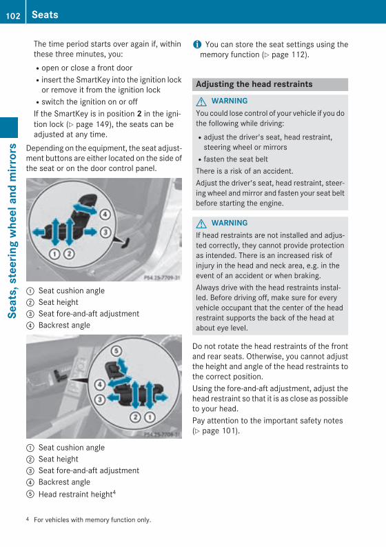
The time period starts over again if, withinthese three minutes, you:Ropen or close a front doorRinsert the SmartKey into the ignition lock
or remove it from the ignition lockRswitch the ignition on or offIf the SmartKey is in position 2 in the igni-tion lock (Y page 149), the seats can beadjusted at any time.
Depending on the equipment, the seat adjust-ment buttons are either located on the side ofthe seat or on the door control panel.
: Seat cushion angle; Seat height= Seat fore-and-aft adjustment? Backrest angle
: Seat cushion angle; Seat height= Seat fore-and-aft adjustment? Backrest angleA Head restraint height4
i You can store the seat settings using thememory function (Y page 112).
Adjusting the head restraints
G WARNINGYou could lose control of your vehicle if you dothe following while driving:Radjust the driver's seat, head restraint,
steering wheel or mirrorsRfasten the seat beltThere is a risk of an accident.Adjust the driver's seat, head restraint, steer-ing wheel and mirror and fasten your seat beltbefore starting the engine.
G WARNINGIf head restraints are not installed and adjus-ted correctly, they cannot provide protectionas intended. There is an increased risk ofinjury in the head and neck area, e.g. in theevent of an accident or when braking.Always drive with the head restraints instal-led. Before driving off, make sure for everyvehicle occupant that the center of the headrestraint supports the back of the head atabout eye level.
Do not rotate the head restraints of the frontand rear seats. Otherwise, you cannot adjustthe height and angle of the head restraints tothe correct position.Using the fore-and-aft adjustment, adjust thehead restraint so that it is as close as possibleto your head.Pay attention to the important safety notes(Y page 101).
4 For vehicles with memory function only.
102 SeatsSe
ats,
ste
erin
g w
heel
and
mirr
ors
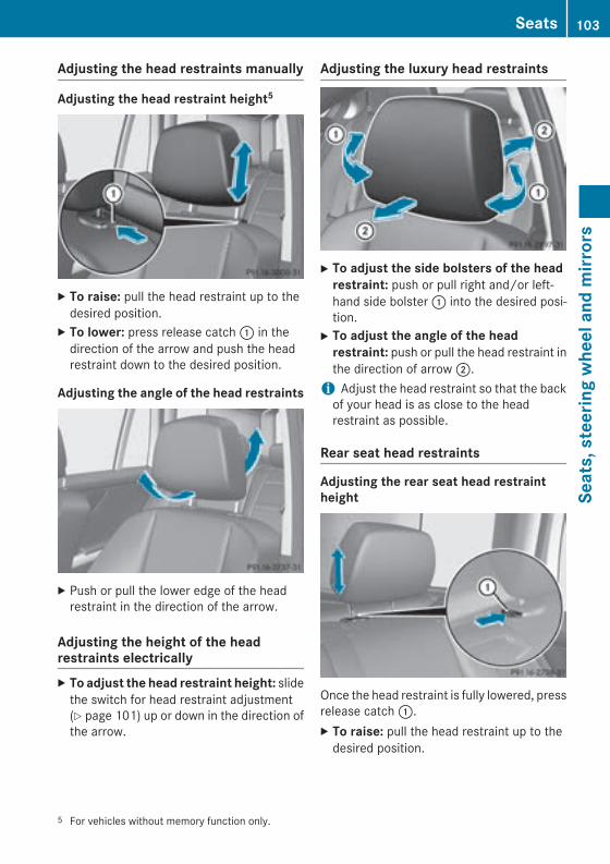
Adjusting the head restraints manually
Adjusting the head restraint height5
X To raise: pull the head restraint up to thedesired position.
X To lower: press release catch : in thedirection of the arrow and push the headrestraint down to the desired position.
Adjusting the angle of the head restraints
X Push or pull the lower edge of the headrestraint in the direction of the arrow.
Adjusting the height of the headrestraints electricallyX To adjust the head restraint height: slide
the switch for head restraint adjustment(Y page 101) up or down in the direction ofthe arrow.
Adjusting the luxury head restraints
X To adjust the side bolsters of the head restraint: push or pull right and/or left-hand side bolster : into the desired posi-tion.
X To adjust the angle of the head restraint: push or pull the head restraint inthe direction of arrow ;.
i Adjust the head restraint so that the backof your head is as close to the headrestraint as possible.
Rear seat head restraints
Adjusting the rear seat head restraintheight
Once the head restraint is fully lowered, pressrelease catch :.X To raise: pull the head restraint up to the
desired position.
5 For vehicles without memory function only.
Seats 103
Seat
s, s
teer
ing
whe
el a
nd m
irror
s
Z
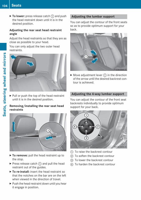
X To lower: press release catch : and pushthe head restraint down until it is in thedesired position.
Adjusting the rear seat head restraintangleAdjust the head restraints so that they are asclose as possible to your head.You can only adjust the two outer headrestraints.
X Pull or push the top of the head restraintuntil it is in the desired position.
Removing/installing the rear seat headrestraints
X To remove: pull the head restraint up tothe stop.
X Press release catch : and pull the headrestraint out of the guides.
X To re-install: insert the head restraint sothat the notches on the bar are on the leftwhen viewed in the direction of travel.
X Push the head restraint down until you hearit engage in position.
Adjusting the lumbar supportYou can adjust the contour of the front seatsso as to provide optimum support for yourback.
X Move adjustment lever : in the directionof the arrow until the desired backrest con-tour is achieved.
Adjusting the 4-way lumbar supportYou can adjust the contour of the front seatbackrests individually to provide optimumsupport for your back.
: To raise the backrest contour; To soften the backrest contour= To lower the backrest contour? To harden the backrest contour
104 SeatsSe
ats,
ste
erin
g w
heel
and
mirr
ors

Switching the seat heating on/off
Switching on/off
G WARNINGRepeatedly switching on the seat heating cancause the seat cushion and backrest pads tobecome very hot. The health of persons withlimited temperature sensitivity or a limitedability to react to excessively high tempera-tures may be affected or they may even sufferburn-like injuries. There is a risk of injury.Therefore, do not switch the seat heating onrepeatedly.
The three red indicator lamps in the buttonindicate the heating level you have selected.
i If the battery voltage is too low, the seatheating may switch off.
Driver's and front-passenger seat
The system automatically switches downfrom level 3 to level 2 after approximatelyeight minutes.The system automatically switches downfrom level 2 to level 1 after approximately tenminutes.The system automatically switches offapproximately 20 minutes after it is set tolevel 1.X Make sure that the SmartKey is in position
1 or 2 in the ignition lock (Y page 149).X To switch on: press button : repeatedly
until the desired heating level is set.X To switch off: press button : repeatedly
until all the indicator lamps go out.
Seats 105
Seat
s, s
teer
ing
whe
el a
nd m
irror
s
Z
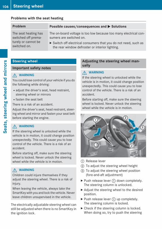
Problems with the seat heating
Problem Possible causes/consequences and M Solutions
The seat heating hasswitched off prema-turely or cannot beswitched on.
The on-board voltage is too low because too many electrical con-sumers are switched on.X Switch off electrical consumers that you do not need, such as
the rear window defroster or interior lighting.
Steering wheel
Important safety notes
G WARNINGYou could lose control of your vehicle if you dothe following while driving:Radjust the driver's seat, head restraint,
steering wheel or mirrorsRfasten the seat beltThere is a risk of an accident.Adjust the driver's seat, head restraint, steer-ing wheel and mirror and fasten your seat beltbefore starting the engine.
G WARNINGIf the steering wheel is unlocked while thevehicle is in motion, it could change positionunexpectedly. This could cause you to losecontrol of the vehicle. There is a risk of anaccident.Before starting off, make sure the steeringwheel is locked. Never unlock the steeringwheel while the vehicle is in motion.
G WARNINGChildren could injure themselves if theyadjust the steering wheel. There is a risk ofinjury.When leaving the vehicle, always take theSmartKey with you and lock the vehicle. Neverleave children unsupervised in the vehicle.
The electrically adjustable steering wheel canstill be adjusted when there is no SmartKey inthe ignition lock.
Adjusting the steering wheel man-ually
G WARNINGIf the steering wheel is unlocked while thevehicle is in motion, it could change positionunexpectedly. This could cause you to losecontrol of the vehicle. There is a risk of anaccident.Before starting off, make sure the steeringwheel is locked. Never unlock the steeringwheel while the vehicle is in motion.
: Release lever; To adjust the steering wheel height= To adjust the steering wheel position
(fore-and-aft adjustment)X Push release lever : down completely.
The steering column is unlocked.X Adjust the steering wheel to the desired
position.X Push release lever : up completely.
The steering column is locked.X Check if the steering column is locked.
When doing so, try to push the steering
106 Steering wheelSe
ats,
ste
erin
g w
heel
and
mirr
ors
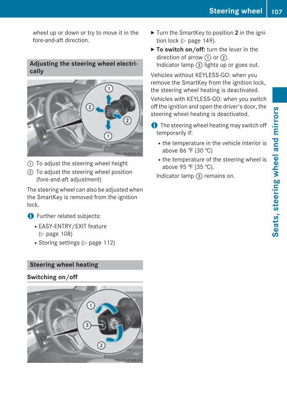
wheel up or down or try to move it in thefore-and-aft direction.
Adjusting the steering wheel electri-cally
: To adjust the steering wheel height; To adjust the steering wheel position
(fore-and-aft adjustment)The steering wheel can also be adjusted whenthe SmartKey is removed from the ignitionlock.
i Further related subjects:REASY-ENTRY/EXIT feature
(Y page 108)RStoring settings (Y page 112)
Steering wheel heating
Switching on/off
X Turn the SmartKey to position 2 in the igni-tion lock (Y page 149).
X To switch on/off: turn the lever in thedirection of arrow : or ;.Indicator lamp = lights up or goes out.
Vehicles without KEYLESS-GO: when youremove the SmartKey from the ignition lock,the steering wheel heating is deactivated.Vehicles with KEYLESS-GO: when you switchoff the ignition and open the driver's door, thesteering wheel heating is deactivated.
i The steering wheel heating may switch offtemporarily if:Rthe temperature in the vehicle interior is
above 86 ‡ (30 †)Rthe temperature of the steering wheel is
above 95 ‡ (35 †).Indicator lamp = remains on.
Steering wheel 107
Seat
s, s
teer
ing
whe
el a
nd m
irror
s
Z
Problems with the steering wheel heating
Problem Possible causes/consequences and M Solutions
The steering wheelheating has switchedoff prematurely or can-not be switched on.
The on-board voltage is too low because too many electrical con-sumers are switched on.X Switch off electrical consumers that you do not need, such as
the rear window defroster or interior lighting.Once the battery is sufficiently charged, the steering wheelheating will switch back on automatically.
EASY-ENTRY/EXIT feature
Important safety notes
G WARNINGWhen the EASY-ENTRY/EXIT feature adjuststhe steering wheel, you and other vehicleoccupants – particularly children – couldbecome trapped. There is a risk of injury.While the EASY-ENTRY/EXIT feature is mak-ing adjustments, make sure that no one hasany body parts in the sweep of the steeringwheel.If somebody becomes trapped:Rpress one of the memory function position
buttons, orRmove the switch for steering wheel adjust-
ment in the opposite direction to that inwhich the steering wheel is moving.
The adjustment process is stopped.
G WARNINGIf you drive off while the EASY-ENTRY/EXITfeature is making adjustments, you could losecontrol of the vehicle. There is a risk of anaccident.Always wait until the adjustment process iscomplete before driving off.
The EASY-ENTRY/EXIT feature makes gettingin and out of your vehicle easier.You can activate and deactivate the EASY-ENTRY/EXIT feature in the on-board com-puter (Y page 233).
Position of the steering wheel when theEASY-ENTRY/EXIT feature is activeThe steering wheel swings upwards whenyou:Rremove the SmartKey from the ignition lockRopen the driver's door with KEYLESS-GO in
position 1Ropen the driver's door and the SmartKey is
in position 0 or 1 in the ignition lock(Y page 149)
i The steering wheel only moves upwards ifit has not already reached the upper stop.
Position of the steering wheel for driv-ingThe steering wheel is moved to the last selec-ted position when:Rthe driver's door is closedRyou insert the SmartKey into the ignition
lockorRyou press the Start/Stop button once on
vehicles with KEYLESS-GOWhen you close the driver's door with theignition switched on, the steering wheel isalso automatically moved to the previouslyset position.The last position of the steering wheel isstored when you switch off the ignition orwhen you store the setting with the memoryfunction (Y page 112).
108 Steering wheelSe
ats,
ste
erin
g w
heel
and
mirr
ors
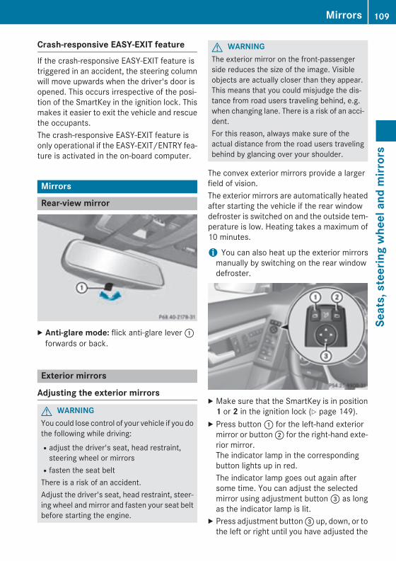
Crash-responsive EASY-EXIT featureIf the crash-responsive EASY-EXIT feature istriggered in an accident, the steering columnwill move upwards when the driver's door isopened. This occurs irrespective of the posi-tion of the SmartKey in the ignition lock. Thismakes it easier to exit the vehicle and rescuethe occupants.The crash-responsive EASY-EXIT feature isonly operational if the EASY-EXIT/ENTRY fea-ture is activated in the on-board computer.
Mirrors
Rear-view mirror
X Anti-glare mode: flick anti-glare lever :forwards or back.
Exterior mirrors
Adjusting the exterior mirrors
G WARNINGYou could lose control of your vehicle if you dothe following while driving:Radjust the driver's seat, head restraint,
steering wheel or mirrorsRfasten the seat beltThere is a risk of an accident.Adjust the driver's seat, head restraint, steer-ing wheel and mirror and fasten your seat beltbefore starting the engine.
G WARNINGThe exterior mirror on the front-passengerside reduces the size of the image. Visibleobjects are actually closer than they appear.This means that you could misjudge the dis-tance from road users traveling behind, e.g.when changing lane. There is a risk of an acci-dent.For this reason, always make sure of theactual distance from the road users travelingbehind by glancing over your shoulder.
The convex exterior mirrors provide a largerfield of vision.The exterior mirrors are automatically heatedafter starting the vehicle if the rear windowdefroster is switched on and the outside tem-perature is low. Heating takes a maximum of10 minutes.
i You can also heat up the exterior mirrorsmanually by switching on the rear windowdefroster.
X Make sure that the SmartKey is in position1 or 2 in the ignition lock (Y page 149).
X Press button : for the left-hand exteriormirror or button ; for the right-hand exte-rior mirror.The indicator lamp in the correspondingbutton lights up in red.The indicator lamp goes out again aftersome time. You can adjust the selectedmirror using adjustment button = as longas the indicator lamp is lit.
X Press adjustment button = up, down, or tothe left or right until you have adjusted the
Mirrors 109
Seat
s, s
teer
ing
whe
el a
nd m
irror
s
Z
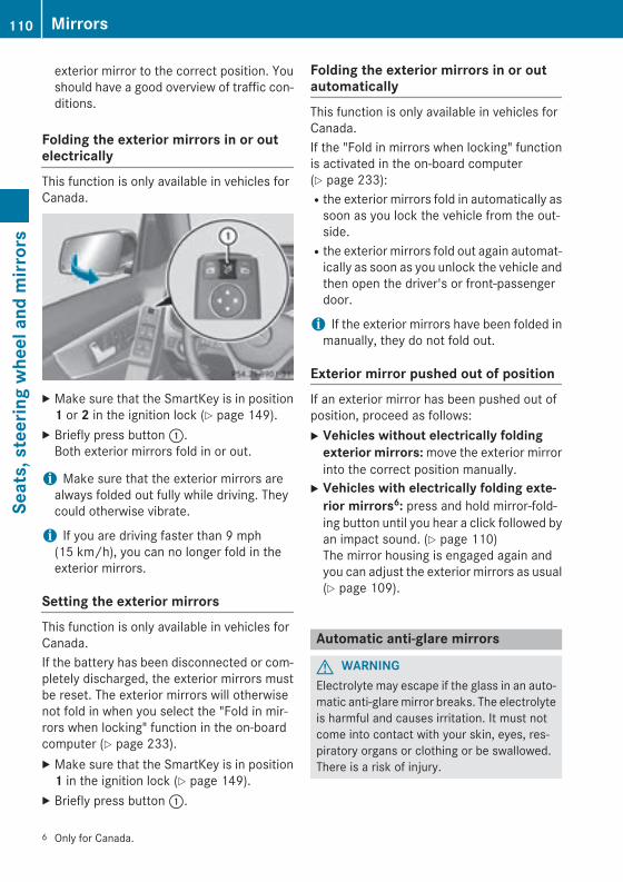
exterior mirror to the correct position. Youshould have a good overview of traffic con-ditions.
Folding the exterior mirrors in or outelectricallyThis function is only available in vehicles forCanada.
X Make sure that the SmartKey is in position1 or 2 in the ignition lock (Y page 149).
X Briefly press button :.Both exterior mirrors fold in or out.
i Make sure that the exterior mirrors arealways folded out fully while driving. Theycould otherwise vibrate.
i If you are driving faster than 9 mph(15 km/h), you can no longer fold in theexterior mirrors.
Setting the exterior mirrorsThis function is only available in vehicles forCanada.If the battery has been disconnected or com-pletely discharged, the exterior mirrors mustbe reset. The exterior mirrors will otherwisenot fold in when you select the "Fold in mir-rors when locking" function in the on-boardcomputer (Y page 233).X Make sure that the SmartKey is in position
1 in the ignition lock (Y page 149).X Briefly press button :.
Folding the exterior mirrors in or outautomaticallyThis function is only available in vehicles forCanada.If the "Fold in mirrors when locking" functionis activated in the on-board computer(Y page 233):Rthe exterior mirrors fold in automatically as
soon as you lock the vehicle from the out-side.Rthe exterior mirrors fold out again automat-
ically as soon as you unlock the vehicle andthen open the driver's or front-passengerdoor.
i If the exterior mirrors have been folded inmanually, they do not fold out.
Exterior mirror pushed out of positionIf an exterior mirror has been pushed out ofposition, proceed as follows:X Vehicles without electrically folding
exterior mirrors: move the exterior mirrorinto the correct position manually.
X Vehicles with electrically folding exte-rior mirrors6: press and hold mirror-fold-ing button until you hear a click followed byan impact sound. (Y page 110)The mirror housing is engaged again andyou can adjust the exterior mirrors as usual(Y page 109).
Automatic anti-glare mirrors
G WARNINGElectrolyte may escape if the glass in an auto-matic anti-glare mirror breaks. The electrolyteis harmful and causes irritation. It must notcome into contact with your skin, eyes, res-piratory organs or clothing or be swallowed.There is a risk of injury.
6 Only for Canada.
110 MirrorsSe
ats,
ste
erin
g w
heel
and
mirr
ors
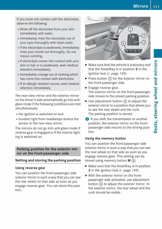
If you come into contact with the electrolyte,observe the following:RRinse off the electrolyte from your skin
immediately with water.RImmediately rinse the electrolyte out of
your eyes thoroughly with clean water.RIf the electrolyte is swallowed, immediately
rinse your mouth out thoroughly. Do notinduce vomiting.RIf electrolyte comes into contact with your
skin or hair or is swallowed, seek medicalattention immediately.RImmediately change out of clothing which
has come into contact with electrolyte.RIf an allergic reaction occurs, seek medical
attention immediately.
The rear-view mirror and the exterior mirroron the driver's side automatically go into anti-glare mode if the following conditions are metsimultaneously:Rthe ignition is switched on andRincident light from headlamps strikes the
sensor in the rear-view mirror.The mirrors do not go into anti-glare mode ifreverse gear is engaged or if the interior light-ing is switched on.
Parking position for the exterior mir-ror on the front-passenger side
Setting and storing the parking position
Using reverse gearYou can position the front-passenger sideexterior mirror in such a way that you can seethe rear wheel on that side as soon as youengage reverse gear. You can store this posi-tion.
X Make sure that the vehicle is stationary andthat the SmartKey is in position 2 in theignition lock (Y page 149).
X Press button ; for the exterior mirror onthe front-passenger side.
X Engage reverse gear.The exterior mirror on the front-passengerside moves to the preset parking position.
X Use adjustment button = to adjust theexterior mirror to a position that allows youto see the rear wheel and the curb.The parking position is stored.
i If you shift the transmission to anotherposition, the exterior mirror on the front-passenger side returns to the driving posi-tion.
Using the memory buttonYou can position the front-passenger sideexterior mirror in such a way that you can seethe rear wheel on that side as soon as youengage reverse gear. This setting can bestored using memory button M ?.X Make sure that the SmartKey is in position
2 in the ignition lock (Y page 149).X With the exterior mirror on the front-
passenger side activated, use adjustmentbutton = to adjust the exterior mirror. Inthe exterior mirror, the rear wheel and thecurb should be visible.
Mirrors 111
Seat
s, s
teer
ing
whe
el a
nd m
irror
s
Z
X Press memory button M ? and one of thearrows on adjustment button = withinthree seconds.The parking position is stored if the exteriormirror does not move.
X If the mirror moves out of position, repeatthe steps.
Calling up a stored parking position set-tingX Turn the SmartKey to position 2 in the igni-
tion lock (Y page 149).X Adjust the exterior mirror on the front-
passenger side using button ;.X Engage reverse gear.
The exterior mirror on the front-passengerside moves to the stored parking position.
The exterior mirror on the front-passengerside moves back to its original position:Ras soon as you exceed a speed of 9 mph
(15 km/h)Rif you press button : for the exterior mir-
ror on the driver's side
Memory function
Storing settings
G WARNINGIf you use the memory function on the driver'sside while driving, you could lose control ofthe vehicle as a result of the adjustmentsbeing made. There is a risk of an accident.Only use the memory function on the driver'sside when the vehicle is stationary.
G WARNINGWhen the memory function adjusts the seat orsteering wheel, you and other vehicle occu-pants – particularly children – could becometrapped. There is a risk of injury.While the memory function is making adjust-ments, make sure that no one has any bodyparts in the sweep of the seat or steering
wheel. If somebody becomes trapped, imme-diately release the memory function positionbutton. The adjustment process is stopped.
G WARNINGChildren could become trapped if they acti-vate the memory function, particularly whenunattended. There is a risk of injury.When leaving the vehicle, always take theSmartKey with you and lock the vehicle. Neverleave children unsupervised in the vehicle.
The memory function can be used at any time,e.g. even when the key isn't in the ignitionlock.With the memory function, you can store upto three different settings, e.g. for three dif-ferent people.The following settings are stored as a singlememory preset:Rposition of the seat, backrest and head
restraintRdriver's side: steering wheel positionRdriver's side: position of the exterior mir-
rors on the driver's and front-passengersides
112 Memory functionSe
ats,
ste
erin
g w
heel
and
mirr
ors
X Adjust the seat (Y page 101).X On the driver's side, adjust the steering
wheel (Y page 107) and the exterior mirrors(Y page 109).
X Briefly press the M memory button andthen press storage position button 1, 2 or 3within three seconds.The settings are stored in the selected pre-set position, and a confirmation tonesounds.
Calling up a stored setting! If you want to move the seat from the fully
reclined position to a stored seat position,first raise the backrest. The seat could oth-erwise be damaged.
X Press and hold the relevant storage posi-tion button 1, 2 or 3 until the seat, steeringwheel and exterior mirrors are in the storedposition.
i The setting procedure is interrupted assoon as you release the storage positionbutton.
Memory function 113
Seat
s, s
teer
ing
whe
el a
nd m
irror
s
Z

114

Useful information ............................ 116Exterior lighting ................................ 116Interior lighting ................................. 121Replacing bulbs ................................. 122Windshield wipers ............................ 126
115
Ligh
ts a
nd w
inds
hiel
d w
iper
s
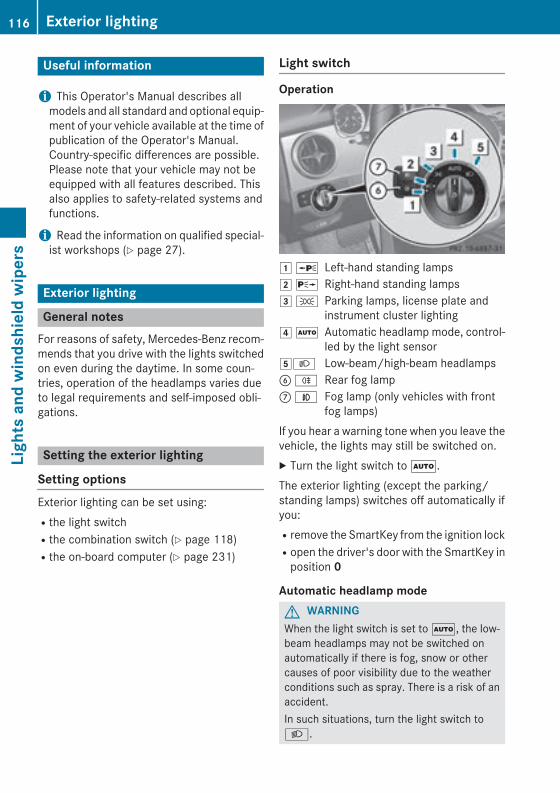
Useful information
i This Operator's Manual describes allmodels and all standard and optional equip-ment of your vehicle available at the time ofpublication of the Operator's Manual.Country-specific differences are possible.Please note that your vehicle may not beequipped with all features described. Thisalso applies to safety-related systems andfunctions.
i Read the information on qualified special-ist workshops (Y page 27).
Exterior lighting
General notesFor reasons of safety, Mercedes-Benz recom-mends that you drive with the lights switchedon even during the daytime. In some coun-tries, operation of the headlamps varies dueto legal requirements and self-imposed obli-gations.
Setting the exterior lighting
Setting optionsExterior lighting can be set using:Rthe light switchRthe combination switch (Y page 118)Rthe on-board computer (Y page 231)
Light switch
Operation
1 W Left-hand standing lamps2 X Right-hand standing lamps3 T Parking lamps, license plate and
instrument cluster lighting4 Ã Automatic headlamp mode, control-
led by the light sensor5L Low-beam/high-beam headlampsB R Rear fog lampC N Fog lamp (only vehicles with front
fog lamps)If you hear a warning tone when you leave thevehicle, the lights may still be switched on.X Turn the light switch to Ã.The exterior lighting (except the parking/standing lamps) switches off automatically ifyou:Rremove the SmartKey from the ignition lockRopen the driver's door with the SmartKey in
position 0
Automatic headlamp modeG WARNINGWhen the light switch is set to Ã, the low-beam headlamps may not be switched onautomatically if there is fog, snow or othercauses of poor visibility due to the weatherconditions such as spray. There is a risk of anaccident.In such situations, turn the light switch toL.
116 Exterior lightingLi
ghts
and
win
dshi
eld
wip
ers
The automatic headlamp feature is only anaid. The driver is responsible for the vehicle'slighting at all times.Ã is the favored light switch setting. Thelight setting is automatically selected accord-ing to the brightness of the ambient light(exception: poor visibility due to weather con-ditions such as fog, snow or spray):RSmartKey in position 1 in the ignition lock:
the parking lamps are switched on or offautomatically depending on the brightnessof the ambient light.RWith the engine running: if you have acti-
vated the "Daytime running lamps" func-tion via the on-board computer, the day-time running lamps or the parking lampsand the low-beam headlamps are switchedon or off automatically depending on thebrightness of the ambient light.
X To switch on automatic headlamp mode: turn the light switch to Ã.
Canada only:The daytime running lamps improve the visi-bility of your vehicle during the day. The day-time running lamps function is required by lawin Canada. It cannot therefore be deactivated.When the engine is running and the vehicle isstationary: if you move the selector lever froma drive position to P, the daytime runninglamps/low-beam headlamps go out afterthree minutes.When the engine is running, the vehicle isstationary and in bright ambient light: if youturn the light switch to T, the daytimerunning lamps and parking lamps switch on.If the engine is running and you turn the lightswitch to L, the manual settings takeprecedence over the daytime running lamps.USA only:The daytime running lamps improve the visi-bility of your vehicle during the day. To do this,the daytime running lamps function must beswitched on using the on-board computer(Y page 231).
If the engine is running and you turn the lightswitch to T or L, the manual settingstake precedence over the daytime runninglamps.
Low-beam headlampsG WARNINGWhen the light switch is set to Ã, the low-beam headlamps may not be switched onautomatically if there is fog, snow or othercauses of poor visibility due to the weatherconditions such as spray. There is a risk of anaccident.In such situations, turn the light switch toL.
Even if the light sensor does not detect that itis dark, the parking lamps and low-beamheadlamps switch on when the ignition isswitched on and the light switch is set to theL position. This is a particularly usefulfunction in the event of rain and fog.X To switch on the low-beam headlamps:
turn the SmartKey in the ignition lock toposition 2 or start the engine.
X Turn the light switch to L.The green L indicator lamp in the instru-ment cluster lights up.
Front fog lampsIn conditions where visibility is poor due tofog, snow or rain, the fog lamps improve vis-ibility as well as making it easier for other roadusers to see you. They can be operatedtogether with the parking lamps or togetherwith the parking lamps and low-beam head-lamps.X To switch on the front fog lamps: turn
the SmartKey in the ignition lock to position2 or start the engine.
X Turn the light switch to L or Ã.
Exterior lighting 117
Ligh
ts a
nd w
inds
hiel
d w
iper
s
Z
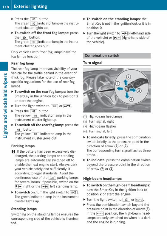
X Press the N button.The green N indicator lamp in the instru-ment cluster lights up.
X To switch off the front fog lamps: pressthe N button.The green N indicator lamp in the instru-ment cluster goes out.
Only vehicles with front fog lamps have thefog lamps function.
Rear fog lampThe rear fog lamp improves visibility of yourvehicle for the traffic behind in the event ofthick fog. Please take note of the country-specific regulations for the use of rear foglamps.X To switch on the rear fog lamps: turn the
SmartKey in the ignition lock to position 2or start the engine.
X Turn the light switch to L or Ã.X Press the R button.
The yellow R indicator lamp in theinstrument cluster lights up.
X To switch off the rear fog lamp: press theR button.The yellow R indicator lamp in theinstrument cluster goes out.
Parking lamps! If the battery has been excessively dis-
charged, the parking lamps or standinglamps are automatically switched off toenable the next engine start. Always parkyour vehicle safely and sufficiently litaccording to legal standards. Avoid thecontinuous use of the T parking lampsfor several hours. If possible, switch on theX right or the W left standing lamp.
X To switch on: turn the light switch to T.The green indicator lamp in the instrumentcluster lights up.
Standing lampsSwitching on the standing lamps ensures thecorresponding side of the vehicle is illumina-ted.
X To switch on the standing lamps: theSmartKey is not in the ignition lock or it is inposition 0.
X Turn the light switch to W (left-hand sideof the vehicle) or X (right-hand side ofthe vehicle).
Combination switch
Turn signal
: High-beam headlamps; Turn signal, right= High-beam flasher? Turn signal, leftX To indicate briefly: press the combination
switch briefly to the pressure point in thedirection of arrow ; or ?.The corresponding turn signal flashes threetimes.
X To indicate: press the combination switchbeyond the pressure point in the directionof arrow ; or ?.
High-beam headlampsX To switch on the high-beam headlamps:
turn the SmartKey in the ignition lock toposition 2 or start the engine.
X Turn the light switch to L or Ã.X Press the combination switch beyond the
pressure point in the direction of arrow :.In the à position, the high-beam head-lamps are only switched on when it is darkand the engine is running.
118 Exterior lightingLi
ghts
and
win
dshi
eld
wip
ers
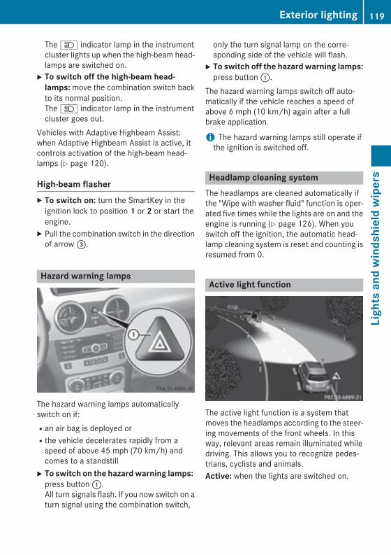
The K indicator lamp in the instrumentcluster lights up when the high-beam head-lamps are switched on.
X To switch off the high-beam head-lamps: move the combination switch backto its normal position.The K indicator lamp in the instrumentcluster goes out.
Vehicles with Adaptive Highbeam Assist:when Adaptive Highbeam Assist is active, itcontrols activation of the high-beam head-lamps (Y page 120).
High-beam flasherX To switch on: turn the SmartKey in the
ignition lock to position 1 or 2 or start theengine.
X Pull the combination switch in the directionof arrow =.
Hazard warning lamps
The hazard warning lamps automaticallyswitch on if:Ran air bag is deployed orRthe vehicle decelerates rapidly from a
speed of above 45 mph (70 km/h) andcomes to a standstill
X To switch on the hazard warning lamps: press button :.All turn signals flash. If you now switch on aturn signal using the combination switch,
only the turn signal lamp on the corre-sponding side of the vehicle will flash.
X To switch off the hazard warning lamps:press button :.
The hazard warning lamps switch off auto-matically if the vehicle reaches a speed ofabove 6 mph (10 km/h) again after a fullbrake application.
i The hazard warning lamps still operate ifthe ignition is switched off.
Headlamp cleaning systemThe headlamps are cleaned automatically ifthe "Wipe with washer fluid" function is oper-ated five times while the lights are on and theengine is running (Y page 126). When youswitch off the ignition, the automatic head-lamp cleaning system is reset and counting isresumed from 0.
Active light function
The active light function is a system thatmoves the headlamps according to the steer-ing movements of the front wheels. In thisway, relevant areas remain illuminated whiledriving. This allows you to recognize pedes-trians, cyclists and animals.Active: when the lights are switched on.
Exterior lighting 119
Ligh
ts a
nd w
inds
hiel
d w
iper
s
Z
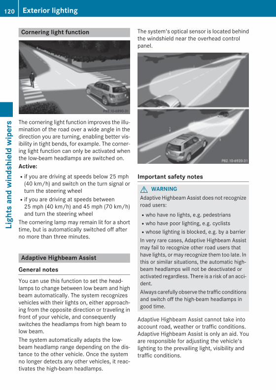
Cornering light function
The cornering light function improves the illu-mination of the road over a wide angle in thedirection you are turning, enabling better vis-ibility in tight bends, for example. The corner-ing light function can only be activated whenthe low-beam headlamps are switched on.Active: Rif you are driving at speeds below 25 mph
(40 km/h) and switch on the turn signal orturn the steering wheelRif you are driving at speeds between
25 mph (40 km/h) and 45 mph (70 km/h)and turn the steering wheel
The cornering lamp may remain lit for a shorttime, but is automatically switched off afterno more than three minutes.
Adaptive Highbeam Assist
General notesYou can use this function to set the head-lamps to change between low beam and highbeam automatically. The system recognizesvehicles with their lights on, either approach-ing from the opposite direction or traveling infront of your vehicle, and consequentlyswitches the headlamps from high beam tolow beam.The system automatically adapts the low-beam headlamp range depending on the dis-tance to the other vehicle. Once the systemno longer detects any other vehicles, it reac-tivates the high-beam headlamps.
The system's optical sensor is located behindthe windshield near the overhead controlpanel.
Important safety notes
G WARNINGAdaptive Highbeam Assist does not recognizeroad users:Rwho have no lights, e.g. pedestriansRwho have poor lighting, e.g. cyclistsRwhose lighting is blocked, e.g. by a barrierIn very rare cases, Adaptive Highbeam Assistmay fail to recognize other road users thathave lights, or may recognize them too late. Inthis or similar situations, the automatic high-beam headlamps will not be deactivated oractivated regardless. There is a risk of an acci-dent.Always carefully observe the traffic conditionsand switch off the high-beam headlamps ingood time.
Adaptive Highbeam Assist cannot take intoaccount road, weather or traffic conditions.Adaptive Highbeam Assist is only an aid. Youare responsible for adjusting the vehicle'slighting to the prevailing light, visibility andtraffic conditions.
120 Exterior lightingLi
ghts
and
win
dshi
eld
wip
ers
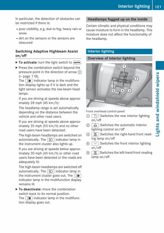
In particular, the detection of obstacles canbe restricted if there is:Rpoor visibility, e.g. due to fog, heavy rain or
snowRdirt on the sensors or the sensors are
obscured
Switching Adaptive Highbeam Assiston/offX To activate: turn the light switch to Ã.X Press the combination switch beyond the
pressure point in the direction of arrow :(Y page 118).The _ indicator lamp in the multifunc-tion display lights up if it is dark and thelight sensor activates the low-beam head-lamps.If you are driving at speeds above approx-imately 28 mph (45 km/h):The headlamp range is set automaticallydepending on the distance between thevehicle and other road users.If you are driving at speeds above approx-imately 35 mph (55 km/h) and no otherroad users have been detected:The high-beam headlamps are switched onautomatically. The K indicator lamp inthe instrument cluster also lights up.If you are driving at speeds below approx-imately 30 mph (45 km/h) or other roadusers have been detected or the roads areadequately lit:The high-beam headlamps are switched offautomatically. The K indicator lamp inthe instrument cluster goes out. The _indicator lamp in the multifunction displayremains lit.
X To deactivate: move the combinationswitch back to its normal position.The _ indicator lamp in the multifunc-tion display goes out.
Headlamps fogged up on the insideCertain climatic and physical conditions maycause moisture to form in the headlamp. Thismoisture does not affect the functionality ofthe headlamp.
Interior lighting
Overview of interior lighting
Front overhead control panel: u Switches the rear interior lighting
on/off; | Switches the automatic interior
lighting control on/off= p Switches the right-hand front read-
ing lamp on/off? c Switches the front interior lighting
on/offA p Switches the left-hand front reading
lamp on/off
Interior lighting 121
Ligh
ts a
nd w
inds
hiel
d w
iper
s
Z
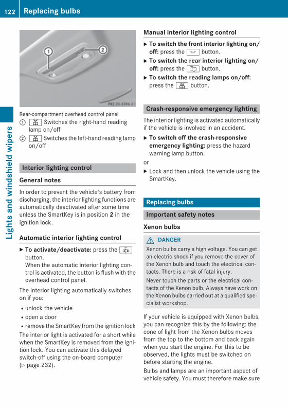
Rear-compartment overhead control panel: p Switches the right-hand reading
lamp on/off; p Switches the left-hand reading lamp
on/off
Interior lighting control
General notesIn order to prevent the vehicle's battery fromdischarging, the interior lighting functions areautomatically deactivated after some timeunless the SmartKey is in position 2 in theignition lock.
Automatic interior lighting controlX To activate/deactivate: press the |
button.When the automatic interior lighting con-trol is activated, the button is flush with theoverhead control panel.
The interior lighting automatically switcheson if you:Runlock the vehicleRopen a doorRremove the SmartKey from the ignition lockThe interior light is activated for a short whilewhen the SmartKey is removed from the igni-tion lock. You can activate this delayedswitch-off using the on-board computer(Y page 232).
Manual interior lighting controlX To switch the front interior lighting on/
off: press the c button.X To switch the rear interior lighting on/
off: press the u button.X To switch the reading lamps on/off:
press the p button.
Crash-responsive emergency lightingThe interior lighting is activated automaticallyif the vehicle is involved in an accident.X To switch off the crash-responsive
emergency lighting: press the hazardwarning lamp button.
orX Lock and then unlock the vehicle using the
SmartKey.
Replacing bulbs
Important safety notes
Xenon bulbs
G DANGERXenon bulbs carry a high voltage. You can getan electric shock if you remove the cover ofthe Xenon bulb and touch the electrical con-tacts. There is a risk of fatal injury.Never touch the parts or the electrical con-tacts of the Xenon bulb. Always have work onthe Xenon bulbs carried out at a qualified spe-cialist workshop.
If your vehicle is equipped with Xenon bulbs,you can recognize this by the following: thecone of light from the Xenon bulbs movesfrom the top to the bottom and back againwhen you start the engine. For this to beobserved, the lights must be switched onbefore starting the engine.Bulbs and lamps are an important aspect ofvehicle safety. You must therefore make sure
122 Replacing bulbsLi
ghts
and
win
dshi
eld
wip
ers
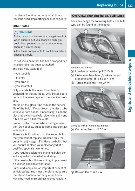
that these function correctly at all times.Have the headlamp setting checked regularly.
Other bulbs
G WARNINGBulbs, lamps and connectors can get very hotwhen operating. If you change a bulb, youcould burn yourself on these components.There is a risk of injury.Allow these components to cool down beforechanging a bulb.
Do not use a bulb that has been dropped or ifits glass tube has been scratched.The bulb may explode if:Ryou touch itRit is hotRyou drop itRyou scratch itOnly operate bulbs in enclosed lampsdesigned for that purpose. Only install sparebulbs of the same type and the specified volt-age.Marks on the glass tube reduce the servicelife of the bulbs. Do not touch the glass tubewith your bare hands. If necessary, clean theglass tube when cold with alcohol or spirit andrub it off with a lint-free cloth.Protect bulbs from moisture during opera-tion. Do not allow bulbs to come into contactwith liquids.There are bulbs other than the Xenon bulbsthat you cannot replace. Replace only thebulbs listed (Y page 123). Have the bulbs thatyou cannot replace yourself changed at aqualified specialist workshop.If you require assistance changing bulbs, con-sult a qualified specialist workshop.If the new bulb still does not light up, consulta qualified specialist workshop.Bulbs and lamps are an important aspect ofvehicle safety. You must therefore make surethat these function correctly at all times.Have the headlamp setting checked regularly.
Overview: changing bulbs/bulb typesYou can change the following bulbs. The bulbtype can be found in the legend.
Halogen headlamps: Low-beam headlamp: H7 55 W; High-beam headlamp/parking lamp/
standing lamp: H15 55 W/15 W= Turn signal lamp: PWY 24 W
Vehicles with Bi-Xenon headlamps: Cornering lamp: H7 55 W
: Backup lamp: W 16 W
Replacing bulbs 123
Ligh
ts a
nd w
inds
hiel
d w
iper
s
Z
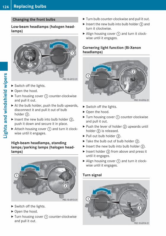
Changing the front bulbs
Low-beam headlamps (halogen head-lamps)
X Switch off the lights.X Open the hood.X Turn housing cover : counter-clockwise
and pull it out.X At the bulb holder, push the bulb upwards,
disconnect it and pull it out of bulbholder ;.
X Insert the new bulb into bulb holder ;,push it down and secure it in place.
X Attach housing cover : and turn it clock-wise until it engages.
High-beam headlamps, standinglamps/parking lamps (halogen head-lamps)
X Switch off the lights.X Open the hood.X Turn housing cover : counter-clockwise
and pull it out.
X Turn bulb counter-clockwise and pull it out.X Insert the new bulb into bulb holder ; and
turn it clockwise.X Align housing cover : and turn it clock-
wise until it engages.
Cornering light function (Bi-Xenonheadlamps)
X Switch off the lights.X Open the hood.X Turn housing cover : counter-clockwise
and pull it out.X Push the lever of holder ; upwards until
holder ; is released.X Pull out bulb holder ;.X Take the bulb out of bulb holder ;.X Insert the new bulb into bulb holder ;.X Insert holder ; from above and press it
until it engages.X Align housing cover : and turn it clock-
wise until it engages.
Turn signal
124 Replacing bulbsLi
ghts
and
win
dshi
eld
wip
ers
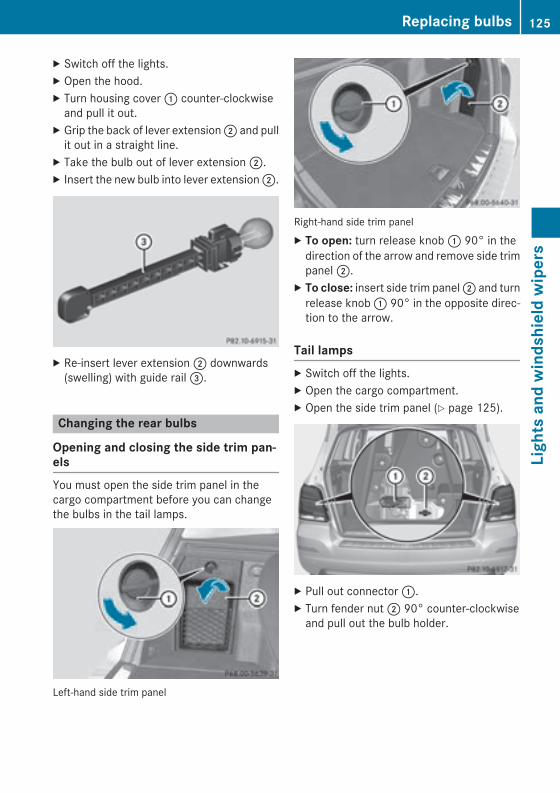
X Switch off the lights.X Open the hood.X Turn housing cover : counter-clockwise
and pull it out.X Grip the back of lever extension ; and pull
it out in a straight line.X Take the bulb out of lever extension ;.X Insert the new bulb into lever extension ;.
X Re-insert lever extension ; downwards(swelling) with guide rail =.
Changing the rear bulbs
Opening and closing the side trim pan-elsYou must open the side trim panel in thecargo compartment before you can changethe bulbs in the tail lamps.
Left-hand side trim panel
Right-hand side trim panelX To open: turn release knob : 90° in the
direction of the arrow and remove side trimpanel ;.
X To close: insert side trim panel ; and turnrelease knob : 90° in the opposite direc-tion to the arrow.
Tail lampsX Switch off the lights.X Open the cargo compartment.X Open the side trim panel (Y page 125).
X Pull out connector :.X Turn fender nut ; 90° counter-clockwise
and pull out the bulb holder.
Replacing bulbs 125
Ligh
ts a
nd w
inds
hiel
d w
iper
s
Z
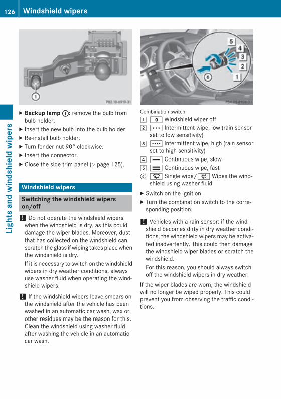
X Backup lamp :: remove the bulb frombulb holder.
X Insert the new bulb into the bulb holder.X Re-install bulb holder.X Turn fender nut 90° clockwise.X Insert the connector.X Close the side trim panel (Y page 125).
Windshield wipers
Switching the windshield wiperson/off
! Do not operate the windshield wiperswhen the windshield is dry, as this coulddamage the wiper blades. Moreover, dustthat has collected on the windshield canscratch the glass if wiping takes place whenthe windshield is dry.If it is necessary to switch on the windshieldwipers in dry weather conditions, alwaysuse washer fluid when operating the wind-shield wipers.
! If the windshield wipers leave smears onthe windshield after the vehicle has beenwashed in an automatic car wash, wax orother residues may be the reason for this.Clean the windshield using washer fluidafter washing the vehicle in an automaticcar wash.
Combination switch1 $ Windshield wiper off2 Ä Intermittent wipe, low (rain sensor
set to low sensitivity)3 Å Intermittent wipe, high (rain sensor
set to high sensitivity)4 ° Continuous wipe, slow5 ¯ Continuous wipe, fastB í Single wipe/î Wipes the wind-
shield using washer fluidX Switch on the ignition.X Turn the combination switch to the corre-
sponding position.
! Vehicles with a rain sensor: if the wind-shield becomes dirty in dry weather condi-tions, the windshield wipers may be activa-ted inadvertently. This could then damagethe windshield wiper blades or scratch thewindshield.For this reason, you should always switchoff the windshield wipers in dry weather.
If the wiper blades are worn, the windshieldwill no longer be wiped properly. This couldprevent you from observing the traffic condi-tions.
126 Windshield wipersLi
ghts
and
win
dshi
eld
wip
ers
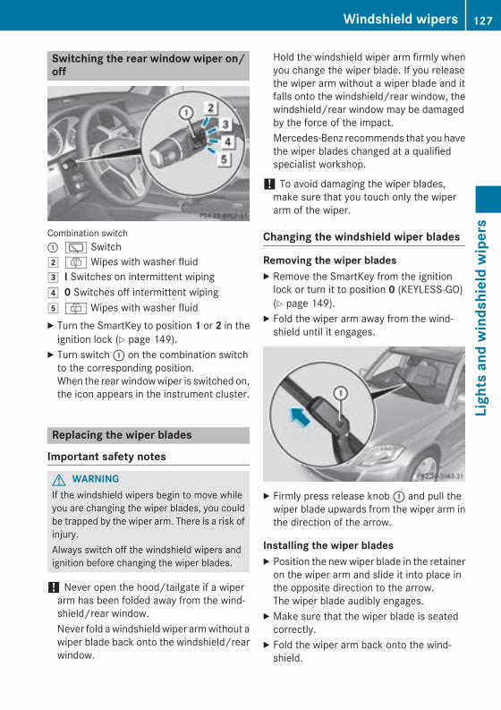
Switching the rear window wiper on/off
Combination switch: è Switch2 ô Wipes with washer fluid3 I Switches on intermittent wiping4 0 Switches off intermittent wiping5 ô Wipes with washer fluidX Turn the SmartKey to position 1 or 2 in the
ignition lock (Y page 149).X Turn switch : on the combination switch
to the corresponding position.When the rear window wiper is switched on,the icon appears in the instrument cluster.
Replacing the wiper blades
Important safety notes
G WARNINGIf the windshield wipers begin to move whileyou are changing the wiper blades, you couldbe trapped by the wiper arm. There is a risk ofinjury.Always switch off the windshield wipers andignition before changing the wiper blades.
! Never open the hood/tailgate if a wiperarm has been folded away from the wind-shield/rear window.Never fold a windshield wiper arm without awiper blade back onto the windshield/rearwindow.
Hold the windshield wiper arm firmly whenyou change the wiper blade. If you releasethe wiper arm without a wiper blade and itfalls onto the windshield/rear window, thewindshield/rear window may be damagedby the force of the impact.Mercedes-Benz recommends that you havethe wiper blades changed at a qualifiedspecialist workshop.
! To avoid damaging the wiper blades,make sure that you touch only the wiperarm of the wiper.
Changing the windshield wiper blades
Removing the wiper bladesX Remove the SmartKey from the ignition
lock or turn it to position 0 (KEYLESS-GO)(Y page 149).
X Fold the wiper arm away from the wind-shield until it engages.
X Firmly press release knob : and pull thewiper blade upwards from the wiper arm inthe direction of the arrow.
Installing the wiper bladesX Position the new wiper blade in the retainer
on the wiper arm and slide it into place inthe opposite direction to the arrow.The wiper blade audibly engages.
X Make sure that the wiper blade is seatedcorrectly.
X Fold the wiper arm back onto the wind-shield.
Windshield wipers 127
Ligh
ts a
nd w
inds
hiel
d w
iper
s
Z
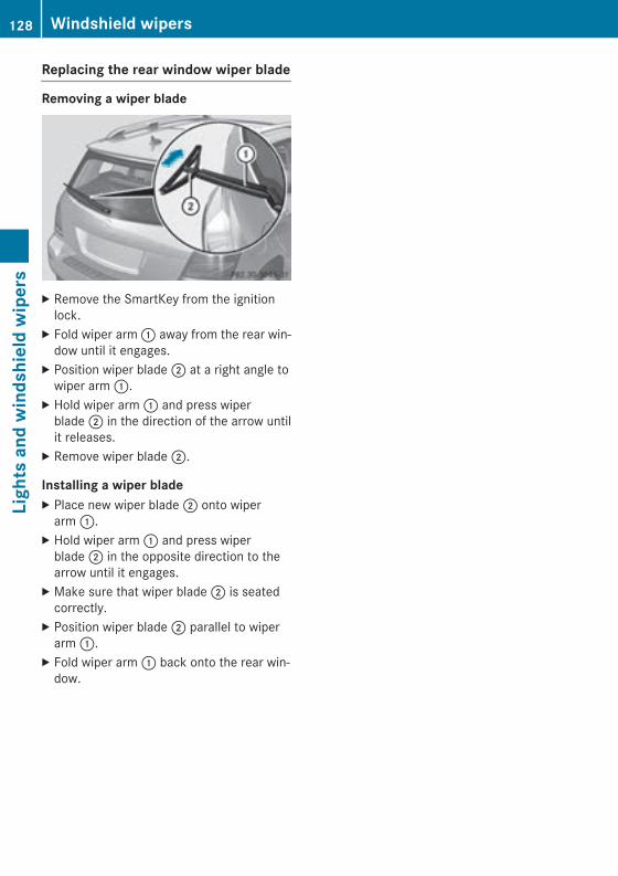
Replacing the rear window wiper blade
Removing a wiper blade
X Remove the SmartKey from the ignitionlock.
X Fold wiper arm : away from the rear win-dow until it engages.
X Position wiper blade ; at a right angle towiper arm :.
X Hold wiper arm : and press wiperblade ; in the direction of the arrow untilit releases.
X Remove wiper blade ;.
Installing a wiper bladeX Place new wiper blade ; onto wiper
arm :.X Hold wiper arm : and press wiper
blade ; in the opposite direction to thearrow until it engages.
X Make sure that wiper blade ; is seatedcorrectly.
X Position wiper blade ; parallel to wiperarm :.
X Fold wiper arm : back onto the rear win-dow.
128 Windshield wipersLi
ghts
and
win
dshi
eld
wip
ers
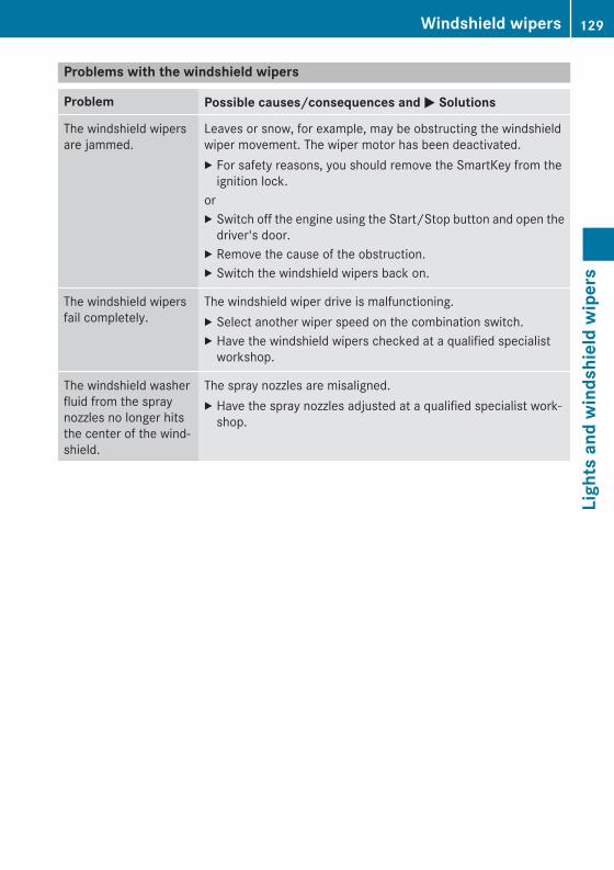
Problems with the windshield wipers
Problem Possible causes/consequences and M Solutions
The windshield wipersare jammed.
Leaves or snow, for example, may be obstructing the windshieldwiper movement. The wiper motor has been deactivated.X For safety reasons, you should remove the SmartKey from the
ignition lock.orX Switch off the engine using the Start/Stop button and open the
driver's door.X Remove the cause of the obstruction.X Switch the windshield wipers back on.
The windshield wipersfail completely.
The windshield wiper drive is malfunctioning.X Select another wiper speed on the combination switch.X Have the windshield wipers checked at a qualified specialist
workshop.
The windshield washerfluid from the spraynozzles no longer hitsthe center of the wind-shield.
The spray nozzles are misaligned.X Have the spray nozzles adjusted at a qualified specialist work-
shop.
Windshield wipers 129
Ligh
ts a
nd w
inds
hiel
d w
iper
s
Z

130

Useful information ............................ 132Overview of climate control sys-tems ................................................... 132Operating the climate control sys-tems ................................................... 137Setting the air vents ......................... 144
131
Clim
ate
cont
rol
Useful information
i This Operator's Manual describes allmodels and all standard and optional equip-ment of your vehicle available at the time ofpublication of the Operator's Manual.Country-specific differences are possible.Please note that your vehicle may not beequipped with all features described. Thisalso applies to safety-related systems andfunctions.
i Read the information on qualified special-ist workshops (Y page 27).
Overview of climate control systems
Important safety notesObserve the settings recommended on thefollowing pages. The windows could other-wise fog up.To prevent the windows from fogging up:Rswitch off climate control only brieflyRswitch on air-recirculation mode only
brieflyRswitch on the cooling with air dehumidifi-
cation functionRswitch on the defrost windshield function
briefly, if requiredClimate control regulates the temperatureand the humidity in the vehicle interior andfilters undesirable substances out of the air.Climate control can only be operated whenthe engine is running. Optimum operation isonly achieved with the side windows and roofclosed.The residual heat function can only be acti-vated or deactivated with the ignitionswitched off (Y page 143).
i Ventilate the vehicle for a brief periodduring warm weather, e.g. using the con-venience opening feature (Y page 93). Thiswill speed up the cooling process and thedesired interior temperature will bereached more quickly.
i The integrated filter filters out most par-ticles of dust and soot and completely fil-ters out pollen. It also reduces gaseous pol-lutants and odors. A clogged filter reducesthe amount of air supplied to the vehicleinterior. For this reason, you should alwaysobserve the interval for replacing the filter,which is specified in the MaintenanceBooklet. As it depends on environmentalconditions, e.g. heavy air pollution, theinterval may be shorter than stated in theMaintenance Booklet.
i It is possible that the dehumidificationfunction of the climate control system maybe activated automatically an hour after theSmartKey has been removed. The vehicle isthen ventilated for 30 minutes.
132 Overview of climate control systemsCl
imat
e co
ntro
l
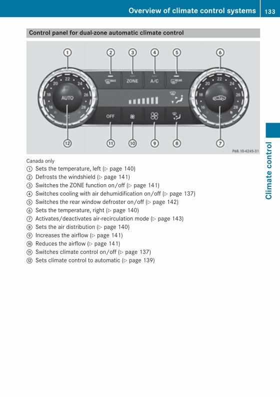
Control panel for dual-zone automatic climate control
Canada only: Sets the temperature, left (Y page 140); Defrosts the windshield (Y page 141)= Switches the ZONE function on/off (Y page 141)? Switches cooling with air dehumidification on/off (Y page 137)A Switches the rear window defroster on/off (Y page 142)B Sets the temperature, right (Y page 140)C Activates/deactivates air-recirculation mode (Y page 143)D Sets the air distribution (Y page 140)E Increases the airflow (Y page 141)F Reduces the airflow (Y page 141)G Switches climate control on/off (Y page 137)H Sets climate control to automatic (Y page 139)
Overview of climate control systems 133
Clim
ate
cont
rol
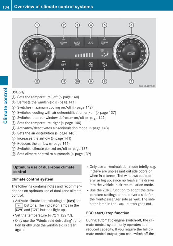
USA only: Sets the temperature, left (Y page 140); Defrosts the windshield (Y page 141)= Switches maximum cooling on/off (Y page 142)? Switches cooling with air dehumidification on/off (Y page 137)A Switches the rear window defroster on/off (Y page 142)B Sets the temperature, right (Y page 140)C Activates/deactivates air-recirculation mode (Y page 143)D Sets the air distribution (Y page 140)E Increases the airflow (Y page 141)F Reduces the airflow (Y page 141)G Switches climate control on/off (Y page 137)H Sets climate control to automatic (Y page 139)
Optimum use of dual-zone climatecontrol
Climate control systemThe following contains notes and recommen-dations on optimum use of dual-zone climatecontrol.RActivate climate control using the à and¿ buttons. The indicator lamps in theà and ¿ buttons light up.RSet the temperature to 72 ‡ (22 †).ROnly use the "Windshield defrosting" func-
tion briefly until the windshield is clearagain.
ROnly use air-recirculation mode briefly, e.g.if there are unpleasant outside odors orwhen in a tunnel. The windows could oth-erwise fog up, since no fresh air is drawninto the vehicle in air-recirculation mode.RUse the ZONE function to adopt the tem-
perature settings on the driver's side forthe front-passenger side as well. The indi-cator lamp in the á button goes out.
ECO start/stop functionDuring automatic engine switch-off, the cli-mate control system only operates at areduced capacity. If you require the full cli-mate control output, you can switch off the
134 Overview of climate control systemsCl
imat
e co
ntro
l

ECO start/stop function by pressing the ECObutton (Y page 154).
Overview of climate control systems 135
Clim
ate
cont
rol
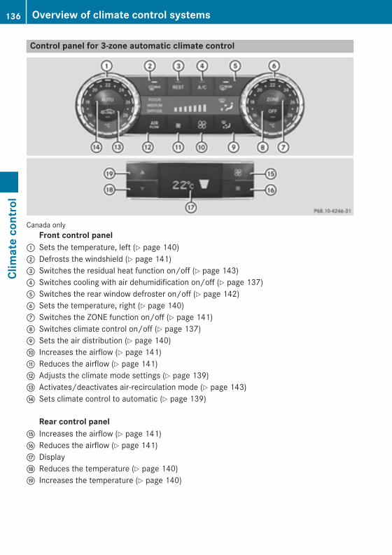
Control panel for 3-zone automatic climate control
Canada onlyFront control panel
: Sets the temperature, left (Y page 140); Defrosts the windshield (Y page 141)= Switches the residual heat function on/off (Y page 143)? Switches cooling with air dehumidification on/off (Y page 137)A Switches the rear window defroster on/off (Y page 142)B Sets the temperature, right (Y page 140)C Switches the ZONE function on/off (Y page 141)D Switches climate control on/off (Y page 137)E Sets the air distribution (Y page 140)F Increases the airflow (Y page 141)G Reduces the airflow (Y page 141)H Adjusts the climate mode settings (Y page 139)I Activates/deactivates air-recirculation mode (Y page 143)J Sets climate control to automatic (Y page 139)
Rear control panel
K Increases the airflow (Y page 141)L Reduces the airflow (Y page 141)M DisplayN Reduces the temperature (Y page 140)O Increases the temperature (Y page 140)
136 Overview of climate control systemsCl
imat
e co
ntro
l
Optimum use of dual-zone climatecontrol
Climate control systemThe following contains instructions and rec-ommendations to enable you to get the mostout of your 3-zone automatic climate control.RActivate climate control using the à and¿ buttons. The indicator lamps in theà and ¿ buttons light up.RIn automatic mode, you can also use theñ button to set the climate mode(FOCUS/MEDIUM/DIFFUSE). TheMEDIUM level is recommended.RSet the temperature to 72 ‡ (22 †).ROnly use the "Windshield defrosting" func-
tion briefly until the windshield is clearagain.ROnly use air-recirculation mode briefly, e.g.
if there are unpleasant outside odors orwhen in a tunnel. The windows could oth-erwise fog up, since no fresh air is drawninto the vehicle in air-recirculation mode.RUse the ZONE function to adopt the tem-
perature settings on the driver's side forthe front-passenger side and the rear com-partment as well. The indicator lamp in theá button goes out.RUse the residual heat function if you want to
heat or ventilate the vehicle interior whenthe ignition is switched off. The residualheat function can only be activated or deac-tivated with the ignition switched off.
ECO start/stop functionDuring automatic engine switch-off, the cli-mate control system only operates at areduced capacity. If you require the full cli-mate control output, you can switch off theECO start/stop function by pressing the ECObutton (Y page 154).
Operating the climate control sys-tems
Switching climate control on/off
General notesWhen the climate control is switched off, theair supply and air circulation are alsoswitched off. The windows could fog up.Therefore, switch off climate control onlybriefly
i Switch on climate control primarily usingthe à button (Y page 139).
Switching on/offX Turn the SmartKey to position 2 in the igni-
tion lock (Y page 149).X To activate: press the à button.
The indicator lamp in the à button lightsup. Airflow and air distribution are set toautomatic mode.
orX Press the ^ button.
The indicator lamp in the ̂ button goesout. The previously selected settings arerestored.
X To deactivate: press the ^ button.The indicator lamp in the ̂ button lightsup.
Activating/deactivating cooling withair dehumidification
General notesIf you deactivate the "Cooling with air-dehu-midification" function, the air inside the vehi-cle will not be cooled. The air inside the vehi-cle will also not be dehumidified. The win-dows can fog up more quickly. Therefore,deactivate the cooling with air-dehumidifica-tion function only briefly.The "Cooling with air dehumidification" func-tion is only available when the engine is run-ning. The air inside the vehicle is cooled and
Operating the climate control systems 137
Clim
ate
cont
rol
dehumidified according to the temperatureselected.Condensation may drip from the underside ofthe vehicle when it is in cooling mode. This isnormal and not a sign that there is a malfunc-tion.
Switching on/offX To activate: press the ¿ button.
The indicator lamp in the ¿ button lightsup.
X To deactivate: press the ¿ button.The indicator lamp in the ¿ button goesout. The "Cooling with air dehumidification"function has a delayed switch-off feature.
138 Operating the climate control systemsCl
imat
e co
ntro
l
Problems with the "Cooling with air dehumidification" function
Problem Possible causes/consequences and M Solutions
The indicator lamp inthe ¿ buttonflashes three times orremains off. The "Cool-ing with air dehumidifi-cation" function cannotbe switched on.
Cooling with air dehumidification has been deactivated due to amalfunction.X Visit a qualified specialist workshop.
Setting climate control to automatic
General notesIn automatic mode, the set temperature ismaintained automatically at a constant level.The system automatically regulates the tem-perature of the dispensed air, the airflow andthe air distribution.The automatic mode functions optimallywhen the "Cooling with air dehumidification"function is activated. If necessary, coolingwith air dehumidification can be deactivated.If you deactivate the "Cooling with air-dehu-midification" function, the air inside the vehi-cle will not be cooled. The air inside the vehi-cle will also not be dehumidified. The win-dows can fog up more quickly. Therefore,deactivate the cooling with air-dehumidifica-tion function only briefly.
Activating/switchingX Turn the SmartKey to position 2 in the igni-
tion lock (Y page 149).X Set the desired temperature.X To activate: press the à button.
The indicator lamp in the à button lightsup. Automatic air distribution and airfloware activated.
3-zone automatic climate control: when auto-matic mode is activated, you can set the cli-mate mode (Y page 139).
X To select manually: press the _ but-ton.
orX Press the K or I button.
The indicator lamp in the à button goesout. Automatic air distribution and airfloware deactivated.
Adjusting the climate mode settingsThis function is only available with 3-zoneautomatic climate control.In automatic mode you can select the follow-ing climate settings:FOCUS high airflow that is set slightly
coolerMEDIUM medium airflow, standard settingDIFFUSE low airflow that is set slightly
warmer and with less draftX Turn the SmartKey to position 2 in the igni-
tion lock (Y page 149).X Press the à button.X Press the ñ button repeatedly until the
required climate setting appears in the dis-play.
Operating the climate control systems 139
Clim
ate
cont
rol
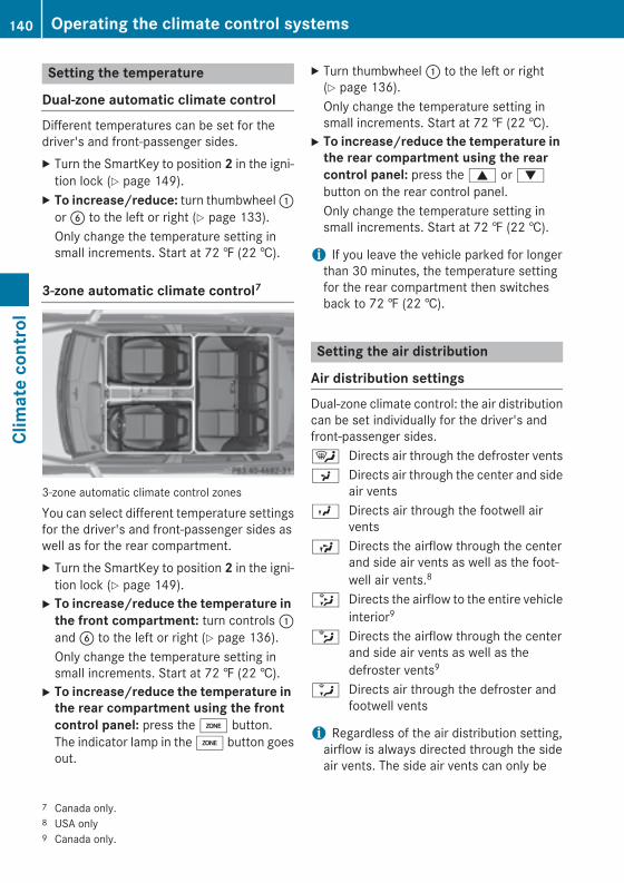
Setting the temperature
Dual-zone automatic climate controlDifferent temperatures can be set for thedriver's and front-passenger sides.X Turn the SmartKey to position 2 in the igni-
tion lock (Y page 149).X To increase/reduce: turn thumbwheel :
or B to the left or right (Y page 133).Only change the temperature setting insmall increments. Start at 72 ‡ (22 †).
3-zone automatic climate control7
3-zone automatic climate control zones
You can select different temperature settingsfor the driver's and front-passenger sides aswell as for the rear compartment.X Turn the SmartKey to position 2 in the igni-
tion lock (Y page 149).X To increase/reduce the temperature in
the front compartment: turn controls :and B to the left or right (Y page 136).Only change the temperature setting insmall increments. Start at 72 ‡ (22 †).
X To increase/reduce the temperature in the rear compartment using the front control panel: press the á button.The indicator lamp in the á button goesout.
X Turn thumbwheel : to the left or right(Y page 136).Only change the temperature setting insmall increments. Start at 72 ‡ (22 †).
X To increase/reduce the temperature in the rear compartment using the rear control panel: press the 9 or :button on the rear control panel.Only change the temperature setting insmall increments. Start at 72 ‡ (22 †).
i If you leave the vehicle parked for longerthan 30 minutes, the temperature settingfor the rear compartment then switchesback to 72 ‡ (22 †).
Setting the air distribution
Air distribution settingsDual-zone climate control: the air distributioncan be set individually for the driver's andfront-passenger sides.¯ Directs air through the defroster ventsP Directs air through the center and side
air ventsO Directs air through the footwell air
ventsS Directs the airflow through the center
and side air vents as well as the foot-well air vents.8
_ Directs the airflow to the entire vehicleinterior9
b Directs the airflow through the centerand side air vents as well as thedefroster vents9
a Directs air through the defroster andfootwell vents
i Regardless of the air distribution setting,airflow is always directed through the sideair vents. The side air vents can only be
7 Canada only.8 USA only9 Canada only.
140 Operating the climate control systemsCl
imat
e co
ntro
l
closed when the controls on the side airvents are turned downwards.
AdjustingX Turn the SmartKey to position 2 in the igni-
tion lock (Y page 149).X Press the _ button repeatedly until the
desired symbol appears in the display.The indicator lamp in the à button goesout. Automatic control is deactivated andthe air distribution is controlled accordingto the selected setting.
Setting the airflowX Turn the SmartKey to position 2 in the igni-
tion lock (Y page 149).X To increase/reduce: press the K orI button.
i You can use 3-zone automatic climatecontrol to set the airflow in the rear com-partment separately.
If the battery is not sufficiently charged,blower output may be reduced. As soon asthe battery is sufficiently charged, full bloweroutput will be available.
Switching the ZONE function on/offThis function is only available in vehicles forCanada.X To activate: press the á button.
The indicator lamp in the á button lightsup.Dual-zone automatic climate control: thetemperature setting for the driver's side isnot adopted for the front-passenger side.3-zone automatic climate control: the tem-perature setting for the driver's side is notadopted for the front-passenger side andthe rear compartment.
When you press the buttons for temperature,airflow or air distribution, the temperature
setting on the driver's side is not adopted forthe other climate control zones.X To deactivate: press the á button.
The indicator lamp in the á button goesout.Dual-zone automatic climate control: thetemperature setting for the driver's side isadopted for the front-passenger side.3-zone automatic climate control: the tem-perature setting for the driver's side isadopted for the front-passenger side andthe rear compartment.
Defrosting the windshieldYou can use this function to defrost the wind-shield or to defrost the inside of the wind-shield and the side windows.
i You should only select the "Windshielddefrosting" function until the windshield isclear again.
X Turn the SmartKey to position 2 in the igni-tion lock (Y page 149).
X To activate: press the ¬ button.The indicator lamp in the ¬ button lightsup.The climate control system switches to thefollowing functions:Rhigh airflowRhigh temperatureRair distribution to the windshield and
front side windowsRair-recirculation mode off
If the battery is not sufficiently charged,blower output may be reduced. As soon asthe battery is sufficiently charged, full bloweroutput will be available.X To deactivate: press the ¬ button.
The indicator lamp in the ¬ button goesout. The previously selected settings arerestored. Air-recirculation mode remainsdeactivated.
or
Operating the climate control systems 141
Clim
ate
cont
rol
X Press the à button.The indicator lamp in the ¬ button goesout. Airflow and air distribution are set toautomatic mode.
orX Turn temperature control : or B counter-
clockwise or clockwise (Y page 133),(Y page 136).
orX Press the K or I button.
MAX COOL maximum coolingThe MAX COOL function is only available invehicles for the USA.MAX COOL is only operational when theengine is running.When you activate MAX COOL, climate con-trol switches to the following functions:Rmaximum coolingRmaximum airflowRair-recirculation mode onX To activate: press the Ù button.
The indicator lamp in the Ù button lightsup.
X To deactivate: press the Ù button.The indicator lamp in the Ù button goesout. The previously selected settings arerestored.
Defrosting the windows
Windows fogged up on the insideX Activate the ¿ cooling with air dehu-
midification function.X Activate automatic mode Ã.X Adjust the side air vents so that the warmed
air is directed to the side windows.X If the windows continue to fog up, activate
the ¬ "Windshield defrosting" function.
i You should only select this setting untilthe windshield is clear again.
Windows fogged up on the outsideX Activate the windshield wipers.X Press the _ button repeatedly until theO or P symbol appears in the dis-play.
X Adjust the side air vents so that no air isdirected to the side windows.
Rear window defroster
General notesThe rear window defroster has a high currentdraw. You should therefore switch it off assoon as the rear window is clear. Otherwise,the rear window defroster switches off auto-matically after several minutes.If the battery voltage is too low, the rear win-dow defroster may switch off.
Switching on/offX Turn the SmartKey to position 2 in the igni-
tion lock (Y page 149).X Press the ¤ button.
The indicator lamp in the ¤ button lightsup or goes out.
142 Operating the climate control systemsCl
imat
e co
ntro
l
Problems with the rear window defroster
Problem Possible causes/consequences and M Solutions
The rear windowdefroster has deactiva-ted prematurely or can-not be activated.
The battery has not been sufficiently charged.X Switch off any consumers that are not required, e.g. reading
lamps, interior lighting or the seat heating.When the battery is sufficiently charged, the rear windowdefroster can be activated again.
Activating/deactivating air-recircula-tion mode
General notesYou can deactivate the flow of fresh air ifunpleasant odors are entering the vehiclefrom outside. The air already inside the vehi-cle will then be recirculated.If you switch on air-recirculation mode, thewindows can fog up more quickly, in particu-lar at low temperatures. Only use air-recircu-lation mode briefly to prevent the windowsfrom fogging up.
Switching on/offX Turn the SmartKey to position 2 in the igni-
tion lock (Y page 149).X To activate: press the g button.
The indicator lamp in the g button lightsup.
i In the event of high pollution levels10 or athigh outside temperatures, air-recircula-tion mode is automatically activated. Whenair-recirculation mode is activated auto-matically, the indicator lamp in the gbutton is not lit.Outside air is added after about30 minutes.
X To deactivate: press the g button.The indicator lamp in the g button goesout.
i Air-recirculation mode deactivates auto-matically:Rafter approximately five minutes at out-
side temperatures below approximately41 ‡ (5 †)Rafter approximately five minutes if cool-
ing with air dehumidification is deactiva-tedRafter approximately 30 minutes at out-
side temperatures above approximately41 ‡ (5 †) if the "Cooling with air dehu-midification" function is activated
Activating/deactivating the residualheat function
General notesThe residual heat function is only available invehicles for Canada with 3-zone automaticclimate control.It is possible to make use of the residual heatof the engine to continue heating the vehiclefor approximately 30 minutes after the enginehas been switched off. The heating timedepends on the set interior temperature.
i The blower will run at a low speed regard-less of the airflow setting.
i If you activate the residual heat functionat high temperatures, only the ventilationwill be activated. The blower runs atmedium speed.
10 3-zone automatic climate control only.
Operating the climate control systems 143
Clim
ate
cont
rol
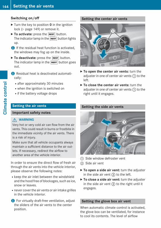
Switching on/offX Turn the key to position 0 in the ignition
lock (Y page 149) or remove it.X To activate: press the Ì button.
The indicator lamp in the Ì button lightsup.
i If the residual heat function is activated,the windows may fog up on the inside.
X To deactivate: press the Ì button.The indicator lamp in the Ì button goesout.
i Residual heat is deactivated automati-cally:Rafter approximately 30 minutesRwhen the ignition is switched onRif the battery voltage drops
Setting the air vents
Important safety notes
G WARNINGVery hot or very cold air can flow from the airvents. This could result in burns or frostbite inthe immediate vicinity of the air vents. Thereis a risk of injury.Make sure that all vehicle occupants alwaysmaintain a sufficient distance to the air out-lets. If necessary, redirect the airflow toanother area of the vehicle interior.
In order to ensure the direct flow of fresh airthrough the air vents into the vehicle interior,please observe the following notes:Rkeep the air inlet between the windshield
and the hood free of blockages, such as ice,snow or leaves.Rnever cover the air vents or air intake grilles
in the vehicle interior.
i For virtually draft-free ventilation, adjustthe sliders of the air vents to the centerposition.
Setting the center air vents
X To open the center air vents: turn theadjuster in one of center air vents : to theleft.
X To close the center air vents: turn theadjuster in one of center air vents : to theright until it engages.
Setting the side air vents
: Side window defroster vent; Side air vent
X To open a side air vent: turn the adjusterin the side air vent ; to the left.
X To close a side air vent: turn the adjusterin the side air vent ; to the right until itengages.
Setting the glove box air ventWhen automatic climate control is activated,the glove box can be ventilated, for instanceto cool its contents. The level of airflow
144 Setting the air ventsCl
imat
e co
ntro
l
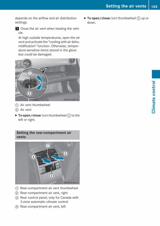
depends on the airflow and air distributionsettings.
! Close the air vent when heating the vehi-cle.At high outside temperatures, open the airvent and activate the "cooling with air dehu-midification" function. Otherwise, temper-ature-sensitive items stored in the glovebox could be damaged.
: Air vent thumbwheel; Air ventX To open/close: turn thumbwheel : to the
left or right.
Setting the rear-compartment airvents
: Rear-compartment air vent thumbwheel; Rear-compartment air vent, right= Rear control panel, only for Canada with
3-zone automatic climate control? Rear-compartment air vent, left
X To open/close: turn thumbwheel : up ordown.
Setting the air vents 145
Clim
ate
cont
rol
Z

146

Useful information ............................ 148Notes on breaking-in a new vehi-cle ....................................................... 148Driving ............................................... 148Automatic transmission ................... 156Refueling ............................................ 162Parking ............................................... 168Driving tips ........................................ 169Driving systems ................................ 175Towing a trailer ................................. 212
147
Driv
ing
and
park
ing
Useful information
i This Operator's Manual describes allmodels and all standard and optional equip-ment of your vehicle available at the time ofpublication of the Operator's Manual.Country-specific differences are possible.Please note that your vehicle may not beequipped with all features described. Thisalso applies to safety-related systems andfunctions.
i Read the information on qualified special-ist workshops (Y page 27).
Notes on breaking-in a new vehicle
Important safety notesThe sensor system of some driving and driv-ing safety systems adjusts automaticallywhile a certain distance is being driven afterthe vehicle has been delivered or afterrepairs. Full system effectiveness is notreached until the end of this teach-in proce-dure.New and replaced brake pads and discs onlyreach their optimum braking effect after sev-eral hundred kilometers of driving. Compen-sate for this by applying greater force to thebrake pedal.
The first 1000 miles (1500 km)The more you look after the engine when it isnew, the more satisfied you will be with itsperformance in the future.RYou should therefore drive at varying vehi-
cle and engine speeds for the first1000 miles (1500 km).RIdeally, for the first 1000 miles (1500 km),
drive in program E.RAvoid heavy loads, e.g. driving at full throt-
tle, during this period.
RChange gear in good time, before the tach-ometer needle is Ô of the way to the redarea of the tachometer.RDo not manually shift to a lower gear to
brake the vehicle.RTry to avoid depressing the accelerator
pedal beyond the point of resistance (kick-down).
After 1000 miles (1500 km), you can increasethe engine speed gradually and acceleratethe vehicle to full speed.
i You should also observe these notes onbreaking in if the engine or parts of the drivetrain on your vehicle have been replaced.
i Always observe the respective speed lim-its.
Driving
Important safety notes
G WARNINGObjects in the driver's footwell can restrict thepedal travel or obstruct a depressed pedal.The operating and road safety of the vehicle isjeopardized. There is a risk of an accident.Make sure that all objects in the vehicle arestowed correctly, and that they cannot enterthe driver's footwell. Install the floormatssecurely and as specified in order to ensuresufficient clearance for the pedals. Do not useloose floormats and do not place floormats ontop of one another.
G WARNINGUnsuitable footwear can hinder correct usageof the pedals, e.g.:Rshoes with thick solesRshoes with high heelsRslippersThere is a risk of an accident.Wear suitable footwear to ensure correctusage of the pedals.
148 DrivingDr
ivin
g an
d pa
rkin
g
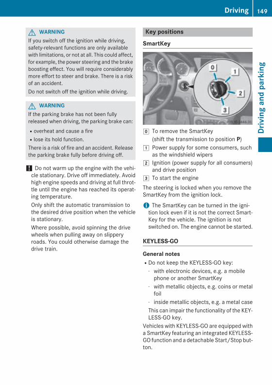
G WARNINGIf you switch off the ignition while driving,safety-relevant functions are only availablewith limitations, or not at all. This could affect,for example, the power steering and the brakeboosting effect. You will require considerablymore effort to steer and brake. There is a riskof an accident.Do not switch off the ignition while driving.
G WARNINGIf the parking brake has not been fullyreleased when driving, the parking brake can:Roverheat and cause a fireRlose its hold function.There is a risk of fire and an accident. Releasethe parking brake fully before driving off.
! Do not warm up the engine with the vehi-cle stationary. Drive off immediately. Avoidhigh engine speeds and driving at full throt-tle until the engine has reached its operat-ing temperature.Only shift the automatic transmission tothe desired drive position when the vehicleis stationary.Where possible, avoid spinning the drivewheels when pulling away on slipperyroads. You could otherwise damage thedrive train.
Key positions
SmartKey
g To remove the SmartKey(shift the transmission to position P)
1 Power supply for some consumers, suchas the windshield wipers
2 Ignition (power supply for all consumers)and drive position
3 To start the engineThe steering is locked when you remove theSmartKey from the ignition lock.
i The SmartKey can be turned in the igni-tion lock even if it is not the correct Smart-Key for the vehicle. The ignition is notswitched on. The engine cannot be started.
KEYLESS-GO
General notesRDo not keep the KEYLESS-GO key:
- with electronic devices, e.g. a mobilephone or another SmartKey
- with metallic objects, e.g. coins or metalfoil
- inside metallic objects, e.g. a metal caseThis can impair the functionality of the KEY-LESS-GO key.
Vehicles with KEYLESS-GO are equipped witha SmartKey featuring an integrated KEYLESS-GO function and a detachable Start/Stop but-ton.
Driving 149
Driv
ing
and
park
ing
Z
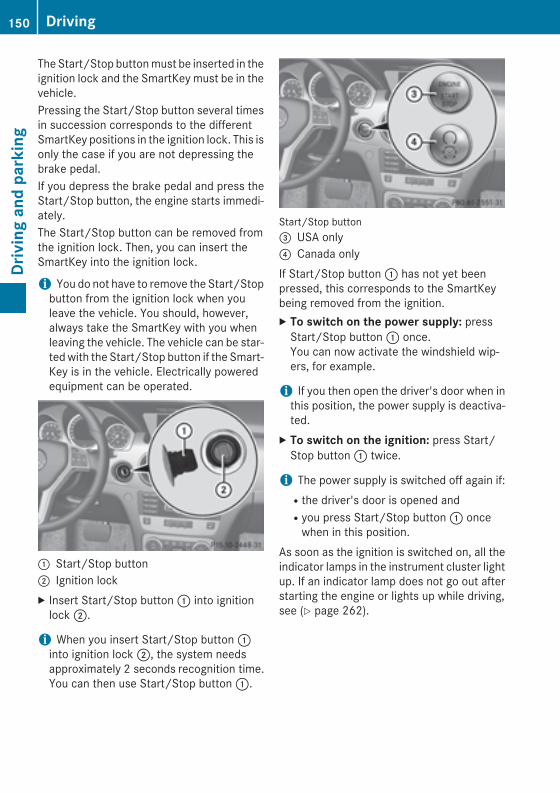
The Start/Stop button must be inserted in theignition lock and the SmartKey must be in thevehicle.Pressing the Start/Stop button several timesin succession corresponds to the differentSmartKey positions in the ignition lock. This isonly the case if you are not depressing thebrake pedal.If you depress the brake pedal and press theStart/Stop button, the engine starts immedi-ately.The Start/Stop button can be removed fromthe ignition lock. Then, you can insert theSmartKey into the ignition lock.
i You do not have to remove the Start/Stopbutton from the ignition lock when youleave the vehicle. You should, however,always take the SmartKey with you whenleaving the vehicle. The vehicle can be star-ted with the Start/Stop button if the Smart-Key is in the vehicle. Electrically poweredequipment can be operated.
: Start/Stop button; Ignition lockX Insert Start/Stop button : into ignition
lock ;.
i When you insert Start/Stop button :into ignition lock ;, the system needsapproximately 2 seconds recognition time.You can then use Start/Stop button :.
Start/Stop button= USA only? Canada onlyIf Start/Stop button : has not yet beenpressed, this corresponds to the SmartKeybeing removed from the ignition.X To switch on the power supply: press
Start/Stop button : once.You can now activate the windshield wip-ers, for example.
i If you then open the driver's door when inthis position, the power supply is deactiva-ted.
X To switch on the ignition: press Start/Stop button : twice.
i The power supply is switched off again if:Rthe driver's door is opened andRyou press Start/Stop button : once
when in this position.As soon as the ignition is switched on, all theindicator lamps in the instrument cluster lightup. If an indicator lamp does not go out afterstarting the engine or lights up while driving,see (Y page 262).
150 DrivingDr
ivin
g an
d pa
rkin
g
Starting the engine
Important safety notes
G WARNINGIf children are left unsupervised in the vehicle,they could:Ropen the doors, thus endangering other
people or road users.Rget out and disrupt traffic.Roperate the vehicle's equipment.Additionally, children could set the vehicle inmotion if, for example, they:Rrelease the parking brake.Rshifting the automatic transmission out of
park position PRStart the engine.There is a risk of an accident and injury.When leaving the vehicle, always take theSmartKey with you and lock the vehicle. Neverleave children or animals unattended in thevehicle. Always keep the SmartKey out ofreach of children.
G WARNINGCombustion engines emit poisonous exhaustgases such as carbon monoxide. Inhalingthese exhaust gases leads to poisoning. Thereis a risk of fatal injury. Therefore never leavethe engine running in enclosed spaces with-out sufficient ventilation.
G WARNINGFlammable materials introduced throughenvironmental influence or by animals canignite if in contact with the exhaust system orparts of the engine that heat up. There is a riskof fire.Carry out regular checks to make sure thatthere are no flammable foreign materials inthe engine compartment or in the exhaustsystem.
! Do not depress the accelerator whenstarting the engine.
General notes
i Vehicles with a gasoline engine: thecatalytic converter is preheated for up to30 seconds after a cold start. The sound ofthe engine may change during this time.
Automatic transmissionX Shift the transmission to position P.
The transmission position display in themultifunction display shows P.
i You can also start the engine when thetransmission is in position N.
Starting procedure with the SmartKey
i To start the engine using the SmartKeyinstead of KEYLESS-GO, pull the Start/Stop button out of the ignition lock.
X To start a gasoline engine: turn theSmartKey to position 3 in the ignition lock(Y page 149) and release it as soon as theengine is running.
X To start a diesel engine: turn the Smart-Key to position 2 in the ignition lock(Y page 149).The % preglow indicator lamp in theinstrument cluster lights up.
X When the % preglow indicator lampgoes out, turn the SmartKey to position 3(Y page 149) and release it as soon as theengine is running.
i You can start the engine without preglowif the engine is warm.
Using KEYLESS-GO to start the engineYou can start the engine if a valid SmartKeywith the integrated KEYLESS-GO function is inthe vehicle. Always take the SmartKey withyou when leaving the vehicle, even if you onlyleave it for a short time. Pay attention to theimportant safety notes.
i The Start/Stop button can be used tostart the vehicle without inserting theSmartKey into the ignition lock. The Start/
Driving 151
Driv
ing
and
park
ing
Z
Stop button must be inserted in the ignitionlock and the SmartKey must be in the vehi-cle.
X Depress the brake pedal and keep itdepressed.
X To start a gasoline engine: press theStart/Stop button once (Y page 149).The engine starts.
X To start a diesel engine: press the Start/Stop button once (Y page 149).Preglow is activated and the engine starts.
Pulling away
Automatic transmission
G WARNINGIf the engine speed is above the idling speedand you engage transmission position D or R,the vehicle could pull away suddenly. There isa risk of an accident.When engaging transmission position D or R,always firmly depress the brake pedal and donot simultaneously accelerate.
It is only possible to shift the transmissionfrom position P to the desired position if youdepress the brake pedal. Only then is theparking lock released. If you do not depressthe brake pedal, the DIRECT SELECT lever canstill be moved but the parking lock remainsengaged.X Depress the brake pedal and keep it
depressed.X Shift the transmission to position D or R.X Release the parking brake (Y page 169).X Release the brake pedal.X Carefully depress the accelerator pedal.
! If a warning tone sounds and theRelease Park. Brake message appearsin the multifunction display, the parkingbrake is still applied. Release the parkingbrake.
i The vehicle locks centrally once you havepulled away. The locking knobs in the doorsdrop down.You can open the doors from the inside atany time.You can also deactivate the automatic lock-ing feature (Y page 232).
i Upshifts take place at higher enginespeeds after a cold start. This helps thecatalytic converter to reach its operatingtemperature more quickly.
Hill start assistHill start assist helps you when pulling awayforwards or in reverse on an uphill gradient. Itholds the vehicle for a short time after youhave removed your foot from the brake pedal.This gives you enough time to move your footfrom the brake pedal to the accelerator pedaland to depress it before the vehicle begins toroll.
G WARNINGAfter a short time, hill start assist will no lon-ger brake your vehicle and it could roll away.There is a risk of an accident and injury.Therefore, quickly move your foot from thebrake pedal to the accelerator pedal. Neverleave the vehicle when it is held by hill startassist.
Hill start assist is not active if:Ryou are pulling away on a level road or on a
downhill gradient.Rthe transmission is in position N.Rthe parking brake is applied.RESP® is malfunctioning.
ECO start/stop function
IntroductionThe ECO start/stop function switches theengine off automatically if the vehicle is stop-ped under certain conditions.
152 DrivingDr
ivin
g an
d pa
rkin
g
The engine starts automatically when thedriver wants to pull away again. The ECOstart/stop function thereby helps you toreduce the fuel consumption and emissionsof your vehicle.
Important safety notes
G WARNINGIf the engine is switched off automatically andyou exit the vehicle, the engine is restartedautomatically. The vehicle may begin moving.There is a risk of accident and injury.If you wish to exit the vehicle, always turn offthe ignition and secure the vehicle againstrolling away.
General notesIf the engine has been switched off automat-ically by the ECO start/stop function, the¤ symbol is shown in the multifunctiondisplay.Every time you switch on the engine using theSmartKey or the Start/Stop button, the ECOstart/stop function is activated.
Automatic engine switch-offIf the vehicle is braked to a standstill in D or N,the ECO start/stop function switches off theengine automatically.The ECO start/stop function is operationalwhen:Rthe indicator lamp in the ECO button is lit
green.Rthe outside temperature is within the range
that is suitable for the system.Rthe engine is at normal operating temper-
ature.Rthe set temperature for the vehicle interior
has been reached.Rthe battery is sufficiently charged.Rthe system detects that the windshield is
not fogged up when the air-conditioningsystem is switched on.
Rthe hood is closed.Rthe driver's door is closed and the driver's
seat belt is fastened.
i All of the vehicle's systems remain activewhen the engine is stopped automatically.
i The HOLD function can also be activatedif the engine has been switched off auto-matically. It is then not necessary to con-tinue applying the brakes during the auto-matic stop phase. When you depress theaccelerator pedal, the engine starts auto-matically and the braking effect of theHOLD function is deactivated.
i The engine can be switched off automat-ically a maximum of four times (first stopand three subsequent stops) in succession.
Automatic engine startThe engine starts automatically if:Ryou switch off the ECO start/stop function
by pressing the ECO button.Rin transmission position D or N the brake
pedal is released and the HOLD function isnot active.Ryou depress the accelerator pedal.Ryou engage reverse gear R.Ryou move the transmission out of position
P.Ryou unfasten your seat belt or open the
driver's door.Rthe vehicle starts to roll.Rthe brake system requires this.Rthe temperature in the vehicle interior devi-
ates from the set range.Rthe system detects moisture on the wind-
shield when the air-conditioning system isswitched on.Rthe battery's condition of charge is too low.
i Shifting the transmission to position Pdoes not start the engine.
Driving 153
Driv
ing
and
park
ing
Z
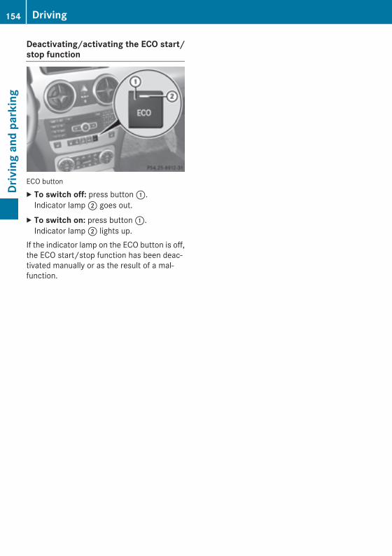
Deactivating/activating the ECO start/stop function
ECO buttonX To switch off: press button :.
Indicator lamp ; goes out.X To switch on: press button :.
Indicator lamp ; lights up.If the indicator lamp on the ECO button is off,the ECO start/stop function has been deac-tivated manually or as the result of a mal-function.
154 DrivingDr
ivin
g an
d pa
rkin
g
Problems with the engine
Problem Possible causes/consequences and M Solutions
The engine does notstart. The starter motorcan be heard.
RThere is a malfunction in the engine electronics.RThere is a malfunction in the fuel supply.X Turn the SmartKey back to position 0 in the ignition lock before
attempting to start the engine again.orX Press the Start/Stop button repeatedly until all indicator lamps
in the instrument cluster go out.X Try to start the engine again (Y page 151). Avoid excessively
long and frequent attempts to start the engine as these will drainthe battery.
If the engine does not start after several attempts:X Consult a qualified specialist workshop.
The engine does notstart. You cannot hearthe starter motor.
The on-board voltage is too low because the battery is too weak ordischarged.X Jump-start the vehicle (Y page 323).If the engine does not start despite attempts to jump-start it:X Consult a qualified specialist workshop.
The starter motor was exposed to a thermal load that was too high.X Allow the starter motor to cool down for approximately two
minutes.X Try to start the engine again.If the engine still does not start:X Consult a qualified specialist workshop.
Driving 155
Driv
ing
and
park
ing
Z

Problem Possible causes/consequences and M Solutions
The engine is not run-ning smoothly and ismisfiring.
There is a malfunction in the engine electronics or in a mechanicalcomponent of the engine management system.X Only depress the accelerator pedal slightly.X Have the cause rectified immediately at a qualified specialist
workshop.Otherwise, non-combusted fuel may get into the catalytic con-verter and damage it.
The coolant tempera-ture gauge shows avalue above 248 ‡(120 †).
The coolant level is too low. The coolant is too hot and the engineis no longer being cooled sufficiently.X Stop as soon as possible and allow the engine and the coolant to
cool down.X Check the coolant level (Y page 303). Observe the warning
notes as you do so and add coolant if necessary.
Automatic transmission
Important safety notes
G WARNINGIf the engine speed is above the idling speedand you engage transmission position D or R,the vehicle could pull away suddenly. There isa risk of an accident.When engaging transmission position D or R,always firmly depress the brake pedal and donot simultaneously accelerate.
G WARNINGThe automatic transmission switches to neu-tral position N when you switch off the engine.The vehicle may roll away. There is a risk of anaccident.After switching off the engine, always switchto parking position P. Prevent the parked vehi-cle from rolling away by applying the parkingbrake.
DIRECT SELECT lever
Overview of transmission positionsThe DIRECT SELECT lever is on the right of thesteering column.
j Park position with parking lockk Reverse geari Neutralh Drive
i The DIRECT SELECT lever always returnsto its original position. The current trans-mission position P, R, N or D appears in thetransmission position display in the multi-function display (Y page 157).
156 Automatic transmissionDr
ivin
g an
d pa
rkin
g
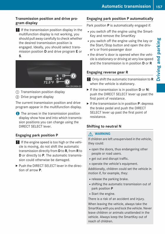
Transmission position and drive pro-gram display
! If the transmission position display in themultifunction display is not working, youshould pull away carefully to check whetherthe desired transmission position isengaged. Ideally, you should select trans-mission position D and drive program E orS.
: Transmission position display; Drive program displayThe current transmission position and driveprogram appear in the multifunction display.
i The arrows in the transmission positiondisplay show how and into which transmis-sion positions you can change using theDIRECT SELECT lever.
Engaging park position P
! If the engine speed is too high or the vehi-cle is moving, do not shift the automatictransmission directly from D to R, from R toD or directly to P. The automatic transmis-sion could otherwise be damaged.
X Push the DIRECT SELECT lever in the direc-tion of arrow P.
Engaging park position P automaticallyPark position P is automatically engaged if:Ryou switch off the engine using the Smart-
Key and remove the SmartKeyRyou switch off the engine using the key or
the Start/Stop button and open the driv-er's or front-passenger doorRthe driver's door is opened when the vehi-
cle is stationary or driving at very low speedand the transmission is in position D or R
Engaging reverse gear R
! Only shift the automatic transmission to Rwhen the vehicle is stationary.
X If the transmission is in position D or N:push the DIRECT SELECT lever up past thefirst point of resistance.
X If the transmission is in position P: depressthe brake pedal and push the DIRECTSELECT lever up past the first point ofresistance.
Shifting to neutral N
G WARNINGIf children are left unsupervised in the vehicle,they could:Ropen the doors, thus endangering other
people or road users.Rget out and disrupt traffic.Roperate the vehicle's equipment.Additionally, children could set the vehicle inmotion if, for example, they:Rrelease the parking brake.Rshifting the automatic transmission out of
park position PRStart the engine.There is a risk of an accident and injury.When leaving the vehicle, always take theSmartKey with you and lock the vehicle. Neverleave children or animals unattended in thevehicle. Always keep the SmartKey out ofreach of children.
Automatic transmission 157
Driv
ing
and
park
ing
Z
X If the transmission is in position D or R:push the DIRECT SELECT lever up or downto the first point of resistance.
X If the transmission is in position P: depressthe brake pedal and push the DIRECTSELECT lever up or down to the first point ofresistance.
If you switch the engine off with the trans-mission in position R or D, the automatictransmission shifts to N automatically.With the SmartKey: if you then open thedriver's door or the front-passenger door orremove the key from the ignition, the auto-matic transmission shifts to P.With KEYLESS-GO: if you then open the driv-er's or front-passenger door, the automatictransmission shifts to P.If you want the automatic transmission toremain in neutral N, e.g. when having thevehicle cleaned in an automatic car wash witha towing system:Using the SmartKey:X Switch on the ignition.X Depress the brake pedal and keep it
depressed.X Shift to neutral N.X Release the brake pedal.X Release the electric parking brake.X Switch off the ignition and leave the Smart-
Key in the ignition lock.Using KEYLESS-GO:X Pull the Start/Stop button out of the igni-
tion.X Insert the SmartKey into the ignition lock.X Switch on the ignition.X Depress the brake pedal and keep it
depressed.X Shift to neutral N.X Release the brake pedal.X Release the electric parking brake.X Switch off the ignition and leave the Smart-
Key in the ignition lock.
Engaging drive position DX If the transmission is in position R or N:
push the DIRECT SELECT lever down pastthe first point of resistance.
X If the transmission is in position P: depressthe brake pedal and push the DIRECTSELECT lever down past the first point ofresistance.
Transmission positions
B Park positionDo not shift the transmission intoposition P (Y page 168) unless thevehicle is stationary. The parkinglock should not be used as a brakewhen parking. Always apply theparking brake in addition to theparking lock in order to secure thevehicle.If the vehicle electronics are mal-functioning, the transmission maybe locked in position P. Have thevehicle electronics checked imme-diately at a qualified specialistworkshop.Park position P is automaticallyengaged if:Ryou switch off the engine using
the SmartKey and remove theSmartKeyRyou switch off the engine using
the key or the Start/Stop buttonand open the driver's or front-passenger doorRthe driver's door is opened when
the vehicle is stationary or driv-ing at very low speed and thetransmission is in position D or R
C Reverse gearOnly shift the transmission to Rwhen the vehicle is stationary.
158 Automatic transmissionDr
ivin
g an
d pa
rkin
g
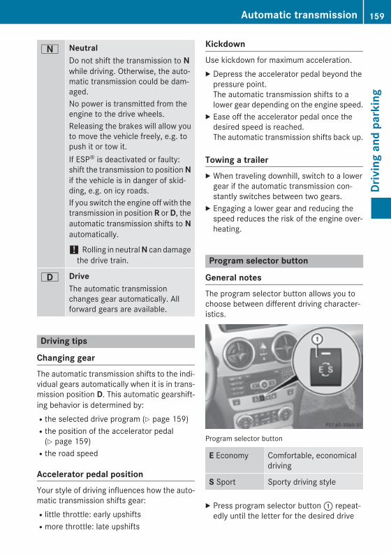
A NeutralDo not shift the transmission to Nwhile driving. Otherwise, the auto-matic transmission could be dam-aged.No power is transmitted from theengine to the drive wheels.Releasing the brakes will allow youto move the vehicle freely, e.g. topush it or tow it.If ESP® is deactivated or faulty:shift the transmission to position Nif the vehicle is in danger of skid-ding, e.g. on icy roads.If you switch the engine off with thetransmission in position R or D, theautomatic transmission shifts to Nautomatically.
! Rolling in neutral N can damagethe drive train.
7 DriveThe automatic transmissionchanges gear automatically. Allforward gears are available.
Driving tips
Changing gearThe automatic transmission shifts to the indi-vidual gears automatically when it is in trans-mission position D. This automatic gearshift-ing behavior is determined by:Rthe selected drive program (Y page 159)Rthe position of the accelerator pedal
(Y page 159)Rthe road speed
Accelerator pedal positionYour style of driving influences how the auto-matic transmission shifts gear:Rlittle throttle: early upshiftsRmore throttle: late upshifts
KickdownUse kickdown for maximum acceleration.X Depress the accelerator pedal beyond the
pressure point.The automatic transmission shifts to alower gear depending on the engine speed.
X Ease off the accelerator pedal once thedesired speed is reached.The automatic transmission shifts back up.
Towing a trailerX When traveling downhill, switch to a lower
gear if the automatic transmission con-stantly switches between two gears.
X Engaging a lower gear and reducing thespeed reduces the risk of the engine over-heating.
Program selector button
General notesThe program selector button allows you tochoose between different driving character-istics.
Program selector button
E Economy Comfortable, economicaldriving
S Sport Sporty driving style
X Press program selector button : repeat-edly until the letter for the desired drive
Automatic transmission 159
Driv
ing
and
park
ing
Z
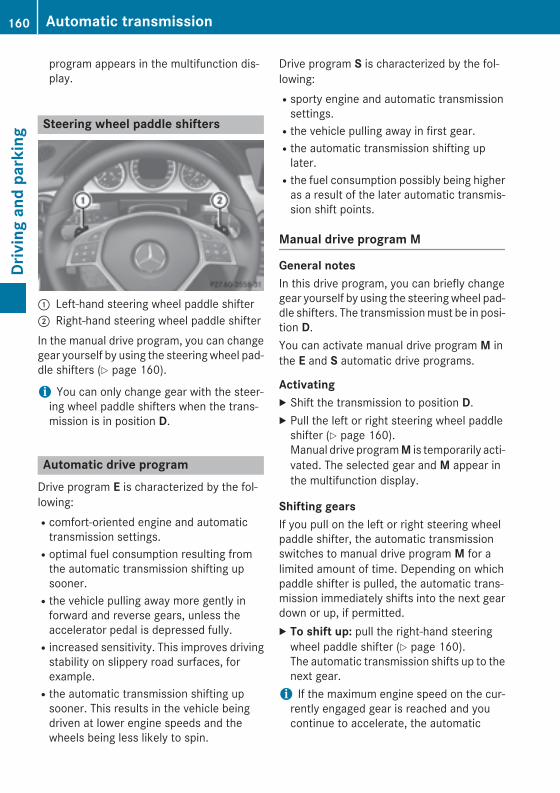
program appears in the multifunction dis-play.
Steering wheel paddle shifters
: Left-hand steering wheel paddle shifter; Right-hand steering wheel paddle shifterIn the manual drive program, you can changegear yourself by using the steering wheel pad-dle shifters (Y page 160).
i You can only change gear with the steer-ing wheel paddle shifters when the trans-mission is in position D.
Automatic drive programDrive program E is characterized by the fol-lowing:Rcomfort-oriented engine and automatic
transmission settings.Roptimal fuel consumption resulting from
the automatic transmission shifting upsooner.Rthe vehicle pulling away more gently in
forward and reverse gears, unless theaccelerator pedal is depressed fully.Rincreased sensitivity. This improves driving
stability on slippery road surfaces, forexample.Rthe automatic transmission shifting up
sooner. This results in the vehicle beingdriven at lower engine speeds and thewheels being less likely to spin.
Drive program S is characterized by the fol-lowing:Rsporty engine and automatic transmission
settings.Rthe vehicle pulling away in first gear.Rthe automatic transmission shifting up
later.Rthe fuel consumption possibly being higher
as a result of the later automatic transmis-sion shift points.
Manual drive program M
General notesIn this drive program, you can briefly changegear yourself by using the steering wheel pad-dle shifters. The transmission must be in posi-tion D.You can activate manual drive program M inthe E and S automatic drive programs.
ActivatingX Shift the transmission to position D.X Pull the left or right steering wheel paddle
shifter (Y page 160).Manual drive program M is temporarily acti-vated. The selected gear and M appear inthe multifunction display.
Shifting gearsIf you pull on the left or right steering wheelpaddle shifter, the automatic transmissionswitches to manual drive program M for alimited amount of time. Depending on whichpaddle shifter is pulled, the automatic trans-mission immediately shifts into the next geardown or up, if permitted.X To shift up: pull the right-hand steering
wheel paddle shifter (Y page 160).The automatic transmission shifts up to thenext gear.
i If the maximum engine speed on the cur-rently engaged gear is reached and youcontinue to accelerate, the automatic
160 Automatic transmissionDr
ivin
g an
d pa
rkin
g
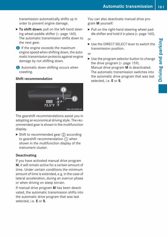
transmission automatically shifts up inorder to prevent engine damage.
X To shift down: pull on the left-hand steer-ing wheel paddle shifter (Y page 160).The automatic transmission shifts down tothe next gear.
i If the engine exceeds the maximumengine speed when shifting down, the auto-matic transmission protects against enginedamage by not shifting down.
i Automatic down shifting occurs whencoasting.
Shift recommendation
The gearshift recommendations assist you inadopting an economical driving style. The rec-ommended gear is shown in the multifunctiondisplay.X Shift to recommended gear ; according
to gearshift recommendation : whenshown in the multifunction display of theinstrument cluster.
DeactivatingIf you have activated manual drive programM, it will remain active for a certain amount oftime. Under certain conditions the minimumamount of time is extended, e.g. in the case oflateral acceleration, during an overrun phaseor when driving on steep terrain.If manual drive program M has been deacti-vated, the automatic transmission shifts intothe automatic drive program that was lastselected, i.e. E or S.
You can also deactivate manual drive pro-gram M yourself:X Pull on the right-hand steering wheel pad-
dle shifter and hold it in place (Y page 160).orX Use the DIRECT SELECT lever to switch the
transmission position.orX Use the program selector button to change
the drive program (Y page 159).Manual drive program M is deactivated.The automatic transmission switches intothe automatic drive program that was lastselected, i.e. E or S.
Automatic transmission 161
Driv
ing
and
park
ing
Z

Problems with the transmission
Problem Possible causes/consequences and M Solutions
The transmission hasproblems shifting gear.
The transmission is losing oil.X Have the transmission checked at a qualified specialist work-
shop immediately.
The acceleration abilityis deteriorating.The transmission nolonger changes gear.
The transmission is in emergency mode.It is only possible to shift into second gear and reverse gear.X Stop the vehicle.X Shift the transmission to position P.X Switch off the engine.X Wait at least ten seconds before restarting the engine.X Shift the transmission to position D or R.
If D is selected, the transmission shifts into second gear; if R isselected, the transmission shifts into reverse gear.
X Have the transmission checked at a qualified specialist work-shop immediately.
Transfer caseThis section is only valid for vehicles with 4-wheel drive (4MATIC). Power is always trans-mitted to both axles.
! Performance tests may only be carriedout on a 2-axle dynamometer. The brakesystem or transfer case could otherwise bedamaged. Contact a qualified specialistworkshop for a performance test.
! To prevent ESP® from intervening, theignition must be switched off (SmartKey inposition 0 or 1) if:Rthe parking brake is being tested on a
brake dynamometer.Rthe vehicle is being towed with only one
axle raised (not permitted for vehicleswith 4MATIC).
The brake system could otherwise be dam-aged.
! Vehicles with 4MATIC must not be towedwith either the front or the rear axle raised,as doing so will damage the transmission.
Refueling
Important safety notes
G WARNINGFuel is highly flammable. If you handle fuelincorrectly, there is a risk of fire and explo-sion.You must avoid fire, open flames, creatingsparks and smoking. Switch off the engineand, if applicable, the auxiliary heating beforerefueling.
G WARNINGFuel is poisonous and hazardous to health.There is a risk of injury.You must make sure that fuel does not comeinto contact with your skin, eyes or clothingand that it is not swallowed. Do not inhale fuelvapors. Keep fuel away from children.
162 RefuelingDr
ivin
g an
d pa
rkin
g
If you or others come into contact with fuel,observe the following:RWash away fuel from skin immediately
using soap and water.RIf fuel comes into contact with your eyes,
immediately rinse them thoroughly withclean water. Seek medical assistance with-out delay.RIf fuel is swallowed, seek medical assis-
tance without delay. Do not induce vomit-ing.RImmediately change out of clothing which
has come into contact with fuel.
G WARNINGElectrostatic buildup can create sparks andignite fuel vapors. There is a risk of fire andexplosion.Always touch the vehicle body before openingthe fuel filler flap or touching the fuel pumpnozzle. Any existing electrostatic buildup isthereby discharged.
G WARNINGVehicles with a diesel engine:If you mix diesel fuel with gasoline, the flashpoint is lower than that of pure diesel fuel.When the engine is running, exhaust systemcomponents could overheat without beingnoticed. There is a risk of fire.Never refuel with gasoline. Never mix gasolinewith diesel fuel.
! Do not use diesel to refuel vehicles with agasoline engine. Do not switch on the igni-tion if you accidentally refuel with thewrong fuel. Otherwise, the fuel will enterthe fuel system. Even small amounts of thewrong fuel could result in damage to thefuel system and the engine. Notify a quali-fied specialist workshop and have the fueltank and fuel lines drained completely.
! Do not use gasoline to refuel vehicles witha diesel engine. Do not switch on the igni-tion if you accidentally refuel with the
wrong fuel. Otherwise, the fuel will enterthe fuel system. Even small amounts of thewrong fuel could result in damage to thefuel system and the engine. The repaircosts are high. Notify a qualified specialistworkshop and have the fuel tank and fuellines drained completely.
! Overfilling the fuel tank could damage thefuel system.
! Take care not to spill any fuel on paintedsurfaces. You could otherwise damage thepaintwork.
! Use a filter when refueling from a fuel can.Otherwise, the fuel lines and/or injectionsystem could be blocked by particles fromthe fuel can.
Do not get into the vehicle again during therefueling process. Otherwise, electrostaticcharge could build up again.If you overfill the fuel tank, fuel could sprayout when the fuel pump nozzle is removed.For further information on fuel and fuel quality(Y page 373).For further information on fuel and fuel qual-ity, see the separate operating instructions.
Refueling
General informationThe fuel filler flap is unlocked or locked auto-matically when you open or close the vehiclewith the SmartKey or with KEYLESS-GO.The position of the 8 fuel filler cap is dis-played in the instrument cluster. The arrownext to the filling pump indicates the side ofthe vehicle.
Refueling 163
Driv
ing
and
park
ing
Z
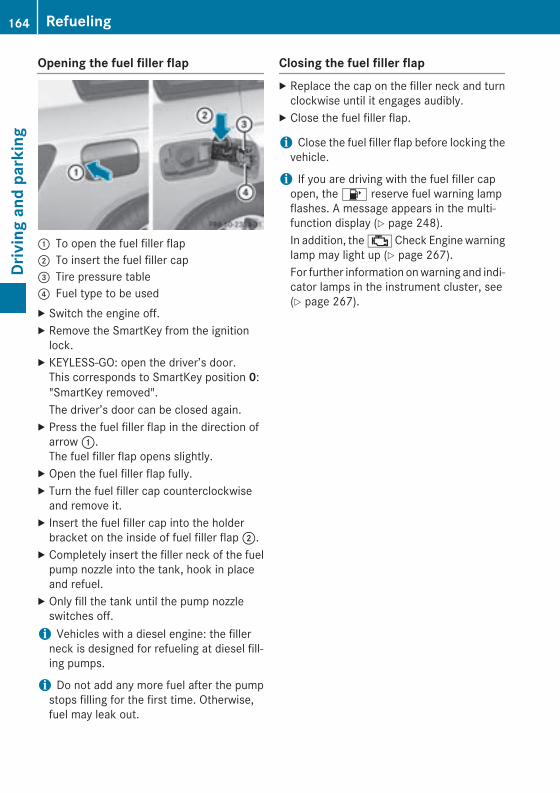
Opening the fuel filler flap
: To open the fuel filler flap; To insert the fuel filler cap= Tire pressure table? Fuel type to be usedX Switch the engine off.X Remove the SmartKey from the ignition
lock.X KEYLESS-GO: open the driver’s door.
This corresponds to SmartKey position 0:"SmartKey removed".The driver’s door can be closed again.
X Press the fuel filler flap in the direction ofarrow :.The fuel filler flap opens slightly.
X Open the fuel filler flap fully.X Turn the fuel filler cap counterclockwise
and remove it.X Insert the fuel filler cap into the holder
bracket on the inside of fuel filler flap ;.X Completely insert the filler neck of the fuel
pump nozzle into the tank, hook in placeand refuel.
X Only fill the tank until the pump nozzleswitches off.
i Vehicles with a diesel engine: the fillerneck is designed for refueling at diesel fill-ing pumps.
i Do not add any more fuel after the pumpstops filling for the first time. Otherwise,fuel may leak out.
Closing the fuel filler flapX Replace the cap on the filler neck and turn
clockwise until it engages audibly.X Close the fuel filler flap.
i Close the fuel filler flap before locking thevehicle.
i If you are driving with the fuel filler capopen, the 8 reserve fuel warning lampflashes. A message appears in the multi-function display (Y page 248).In addition, the ; Check Engine warninglamp may light up (Y page 267).For further information on warning and indi-cator lamps in the instrument cluster, see(Y page 267).
164 RefuelingDr
ivin
g an
d pa
rkin
g
Problems with fuel and the fuel tank
Problem Possible causes/consequences and M Solutions
Fuel is leaking from thevehicle.
The fuel line or the fuel tank is faulty.
G WARNINGRisk of explosion or fire.X Turn the SmartKey to position 0 immediately and remove it
(Y page 149).X Do not restart the engine under any circumstances.X Consult a qualified specialist workshop.
The engine does notstart.
The fuel tank of a vehicle with a diesel engine has been run com-pletely dry.X Refuel the vehicle with at least 5.3 US qt (5 liters) of diesel.X Turn the ignition on for approximately ten seconds
(Y page 149).X Start the engine continuously for up to ten seconds until it runs
smoothly.If the engine does not start:X Turn the ignition on again for approximately ten seconds
(Y page 149).X Start the engine again continuously for up to ten seconds until it
runs smoothly.If the engine does not start after three attempts:X Consult a qualified specialist workshop.
The fuel filler flap can-not be opened.
The fuel filler flap is not unlocked.X Unlock the vehicle (Y page 78).
The SmartKey battery is discharged or nearly discharged.X Unlock the vehicle using the mechanical key (Y page 80).
The fuel filler flap is unlocked, but the opening mechanism is jam-med.X Consult a qualified specialist workshop.
DEF (BlueTEC vehicles only)
Important notes on useTo function properly, BlueTEC exhaust gasaftertreatment must be operated with thereducing agent DEF. Adding DEF is one of the
tasks performed during maintenance. Undernormal operating conditions, a tank of DEFlasts until the next service due date.When the supply of DEF is almost used up, theCheck Additive See Operator's Manual
Refueling 165
Driv
ing
and
park
ing
Z

message is shown in the multifunction dis-play.When the DEF supply drops to a minimum, theRemaining Starts: 16 message is shownin the multifunction display.If the Remaining Starts: 16 messageappears in the multifunction display, you canstart the engine another 16 times. If DEF isnot refilled, you will subsequently be unable to start the engine. Refill the DEF tank witharound 1 gal (3.8 l) of DEF or have the DEFtank refilled at a qualified specialist work-shop.Use the special DEF refill bottle when addingDEF between maintenance intervals. Contacta qualified specialist workshop with any ques-tions or, if necessary, contact Roadside Assis-tance (Y page 24).If the outside temperature is below 12 ‡(Ò11 †) it may be difficult to top up. If DEF isfrozen and there is an active warning indica-tor, it may not be possible to add DEF. Parkthe vehicle in a warmer place, e.g. in a garage,until DEF has become fluid again. It will thenbe possible to add DEF again. Alternatively,have the DEF tank refilled at a qualified spe-cialist workshop.Further information about BlueTEC exhaustgas aftertreatment and DEF is available at anyauthorized Mercedes-Benz Center.
Important safety notesDEF is a water-soluble fluid for the exhaustgas aftertreatment of diesel engines. It is:Rnot poisonousRcolorless and odorlessRnot flammableWhen you open the DEF container, smallamounts of ammonia vapor may be released.Ammonia vapors have a pungent odor and areparticularly irritating to the skin, to mucousmembranes and to the eyes. You may expe-rience a burning sensation in your eyes, noseand throat. Coughing and watering of theeyes are possible.
Do not inhale ammonia vapors. Fill the DEFtank only in well-ventilated areas.DEF must not come into contact with yourskin, eyes or clothing and must not be swal-lowed. Keep DEF away from children.If you or other persons come into contact withDEF, observe the following:RRinse DEF from your skin immediately with
soap and water.RIf DEF comes into contact with your eyes,
immediately rinse them thoroughly withclean water. Seek medical assistance with-out delay.RIf DEF has been swallowed, rinse your
mouth out immediately. Drink plenty ofwater. Seek medical assistance withoutdelay.RChange out of clothing contaminated with
DEF immediately.
! Only use DEF in accordance withISO 22241. Do not mix any additives withDEF, and do not dilute DEF with water. Thismay destroy the BlueTEC exhaust gas after-treatment system.
! Rinse surfaces that have come into con-tact with DEF immediately with water orremove DEF using a damp cloth and coldwater. If the DEF has already crystallized,use a sponge and cold water to clean it. DEFresidues crystallize after time and contam-inate the affected surfaces.
! DEF is not a fuel additive and must not beadded to the fuel tank. If DEF is added tothe fuel tank, this can lead to engine dam-age.
! Only screw on the DEF refill bottle hand-tight. It could otherwise be damaged.
The DEF filler neck is under the cargo com-partment floor.X Switch the ignition off.X Open the tailgate.X Lift up the cargo compartment floor
(Y page 314).
166 RefuelingDr
ivin
g an
d pa
rkin
g
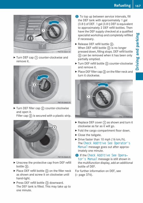
X Turn DEF cap : counter-clockwise andremove it.
X Turn DEF filler cap ; counter-clockwiseand open it.Filler cap ; is secured with a plastic strip.
X Unscrew the protective cap from DEF refillbottle =.
X Place DEF refill bottle = on the filler neckas shown and screw it on clockwise untilhand-tight.
X Press DEF refill bottle = downward.The DEF tank is filled. This may take up toone minute.
i To top up between service intervals, fillthe DEF tank with approximately 1 gal(3.8 l) of DEF. 1 gal (3.8 l) DEF is equivalentto approximately 2 DEF refill bottles. Thenhave the DEF supply checked at a qualifiedspecialist workshop and completely refilledif necessary.
X Release DEF refill bottle =.When DEF refill bottle = is no longerpressed down, filling stops. DEF refill bottle= can be removed when it has been onlypartially emptied.
X Turn DEF refill bottle = counter-clockwiseand remove it.
X Place DEF filler cap ; on the filler neck andturn it clockwise.
X Replace DEF cover : as shown and turn itclockwise as far as it will go.
X Fold the cargo compartment floor down.X Close the tailgate.X Drive faster than 10 mph (16 km/h).
The Check Additive See Operator's Manual message goes out after approx-imately one minute.
i If the Check Additive See Opera‐tor's Manual message is still shown inthe multifunction display, add an additionalbottle of DEF.
For further information on DEF, see(Y page 376).
Refueling 167
Driv
ing
and
park
ing
Z
Parking
Important safety notes
G WARNINGFlammable material such as leaves, grass ortwigs may ignite if they come into contact withhot parts of the exhaust system or exhaustgas flow. There is a risk of fire.Park the vehicle so that no flammable mate-rials come into contact with parts of the vehi-cle which are hot. Take particular care not topark on dry grassland or harvested grainfields.
G WARNINGIf you switch off the ignition while driving,safety-relevant functions are only availablewith limitations, or not at all. This could affect,for example, the power steering and the brakeboosting effect. You will require considerablymore effort to steer and brake. There is a riskof an accident.Do not switch off the ignition while driving.
G WARNINGIf you leave children unsupervised in the vehi-cle, they could set it in motion by, for example:Rrelease the parking brake.Rshift the automatic transmission out of the
parking position P.Rstart the engine.In addition, they may operate vehicle equip-ment and become trapped. There is a risk ofan accident and injury.When leaving the vehicle, always take theSmartKey with you and lock the vehicle. Neverleave children unsupervised in the vehicle.
! Always secure the vehicle correctlyagainst rolling away. Otherwise, the vehicleor its drivetrain could be damaged.
To ensure that the vehicle is secured againstrolling away unintentionally:Rthe parking brake must be applied.Rthe transmission must be in position P and
the SmartKey must be removed from theignition lock.Rthe front wheels must be turned towards
the curb on steep uphill or downhill gradi-ents.
Switching off the engine
Important safety notes
G WARNINGThe automatic transmission switches to neu-tral position N when you switch off the engine.The vehicle may roll away. There is a risk of anaccident.After switching off the engine, always switchto parking position P. Prevent the parked vehi-cle from rolling away by applying the parkingbrake.
Vehicles with automatic transmissionX Apply the parking brake firmly.X Shift the transmission to position P.
Using the SmartKeyX Turn the SmartKey to position 0 in the igni-
tion lock and remove it.The immobilizer is activated.
i The SmartKey can only be removed if thetransmission is in position P.
Using KEYLESS-GOX Press the Start/Stop button (Y page 149).
The engine stops and all the indicatorlamps in the instrument cluster go out.
i When the driver's door is closed, this cor-responds to key position 1. When the driv-er's door is open, this corresponds to keyposition 0: "Key removed".
168 ParkingDr
ivin
g an
d pa
rkin
g
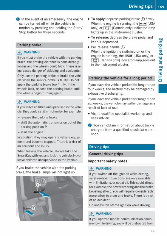
i In the event of an emergency, the enginecan be turned off while the vehicle is inmotion by pressing and holding the Start/Stop button for three seconds.
Parking brake
G WARNINGIf you must brake the vehicle with the parkingbrake, the braking distance is considerablylonger and the wheels could lock. There is anincreased danger of skidding and accidents.Only use the parking brake to brake the vehi-cle when the service brake is faulty. Do notapply the parking brake too firmly. If thewheels lock, release the parking brake untilthe wheels begin turning again.
G WARNINGIf you leave children unsupervised in the vehi-cle, they could set it in motion by, for example:Rrelease the parking brake.Rshift the automatic transmission out of the
parking position P.Rstart the engine.In addition, they may operate vehicle equip-ment and become trapped. There is a risk ofan accident and injury.When leaving the vehicle, always take theSmartKey with you and lock the vehicle. Neverleave children unsupervised in the vehicle.
If you brake the vehicle with the parkingbrake, the brake lamps will not light up.
X To apply: depress parking brake ; firmly.When the engine is running, the $ (USAonly) or J (Canada only) indicator lamplights up in the instrument cluster.
X To release: depress the brake pedal andkeep it depressed.
X Pull release handle :.When the ignition is switched on or theengine is running, the $ (USA only) orJ (Canada only) indicator lamp goes outin the instrument cluster.
Parking the vehicle for a long periodIf you leave the vehicle parked for longer thanfour weeks, the battery may be damaged byexhaustive discharging.If you leave the vehicle parked for longer thansix weeks, the vehicle may suffer damage as aresult of lack of use.X Visit a qualified specialist workshop and
seek advice.
i You can obtain information about tricklechargers from a qualified specialist work-shop.
Driving tips
General driving tips
Important safety notes
G WARNINGIf you switch off the ignition while driving,safety-relevant functions are only availablewith limitations, or not at all. This could affect,for example, the power steering and the brakeboosting effect. You will require considerablymore effort to steer and brake. There is a riskof an accident.Do not switch off the ignition while driving.
G WARNINGIf you operate mobile communication equip-ment while driving, you will be distracted from
Driving tips 169
Driv
ing
and
park
ing
Z
traffic conditions. You could also lose controlof the vehicle. There is a risk of an accident.Only operate this equipment when the vehicleis stationary.
Observe the legal requirements for the coun-try in which you are driving. Some jurisdic-tions prohibit the driver from using a mobilephone while driving a vehicle.If you make a call while driving, always usehands-free mode. Only operate the telephonewhen the traffic situation permits. If you areunsure, pull over to a safe location and stopbefore operating the telephone.Bear in mind that at a speed of only 30 mph(approximately 50 km/h), the vehicle coversa distance of 44 ft (approximately 14 m) persecond.
Drive sensibly – save fuelObserve the following tips to save fuel:X The tires should always be inflated to the
recommended tire pressure.X Remove unnecessary loads.X Remove roof racks when they are not nee-
ded.X Warm up the engine at low engine speeds.X Avoid frequent acceleration or braking.X Have all maintenance work carried out as
indicated by the service intervals in theMaintenance Booklet or by the serviceinterval display.
Fuel consumption also increases when driv-ing in cold weather, in stop-start traffic and inhilly terrain.
Drinking and driving
G WARNINGDrinking and driving and/or taking drugs anddriving are very dangerous combinations.Even a small amount of alcohol or drugs canaffect your reflexes, perceptions and judg-ment.
The possibility of a serious or even fatal acci-dent is greatly increased when you drink ortake drugs and drive.Do not drink or take drugs and drive or allowanyone to drive who has been drinking or tak-ing drugs.
Emission control
G WARNINGCombustion engines emit poisonous exhaustgases such as carbon monoxide. Inhalingthese exhaust gases leads to poisoning. Thereis a risk of fatal injury. Therefore never leavethe engine running in enclosed spaces with-out sufficient ventilation.
Certain engine systems are designed to keepthe level of poisonous components in exhaustfumes within legal limits.These systems only work at peak efficiency ifthey are serviced exactly in accordance withthe manufacturer's specifications. For thisreason, all work on the engine must be carriedout by qualified and authorized Mercedes-Benz technicians.The engine settings must not be changedunder any circumstances. Furthermore, allspecific service work must be carried out atregular intervals and in accordance with theMercedes-Benz service requirements. Detailscan be found in the Maintenance Booklet.
ECO displayThe ECO display provides feedback on howeconomical your driving characteristics are.The ECO display assists you in achieving themost economical driving style for the selec-ted settings and prevailing conditions. Yourdriving style can significantly influence thevehicle's consumption.
170 Driving tipsDr
ivin
g an
d pa
rkin
g
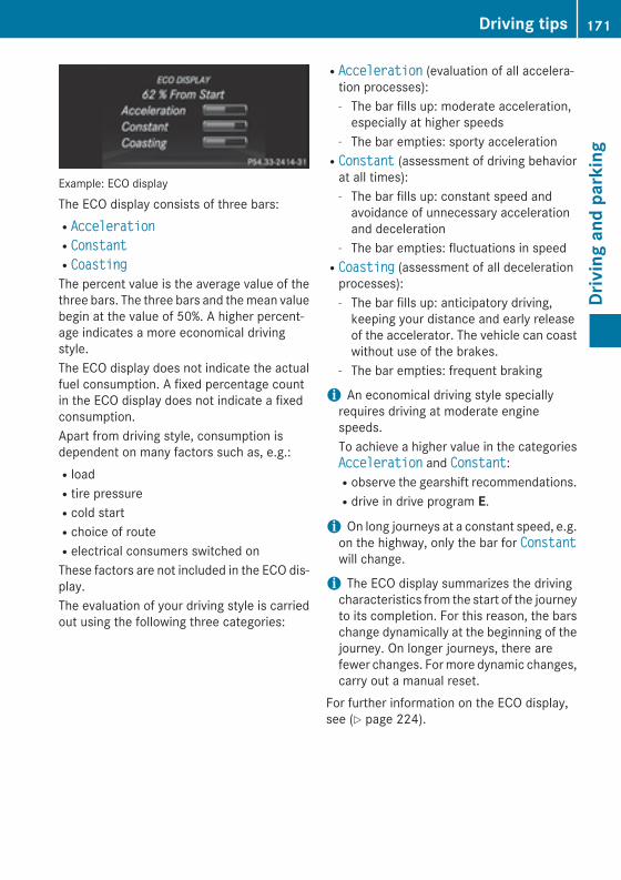
Example: ECO display
The ECO display consists of three bars:RAccelerationRConstantRCoastingThe percent value is the average value of thethree bars. The three bars and the mean valuebegin at the value of 50%. A higher percent-age indicates a more economical drivingstyle.The ECO display does not indicate the actualfuel consumption. A fixed percentage countin the ECO display does not indicate a fixedconsumption.Apart from driving style, consumption isdependent on many factors such as, e.g.:RloadRtire pressureRcold startRchoice of routeRelectrical consumers switched onThese factors are not included in the ECO dis-play.The evaluation of your driving style is carriedout using the following three categories:
RAcceleration (evaluation of all accelera-tion processes):- The bar fills up: moderate acceleration,
especially at higher speeds- The bar empties: sporty accelerationRConstant (assessment of driving behavior
at all times):- The bar fills up: constant speed and
avoidance of unnecessary accelerationand deceleration
- The bar empties: fluctuations in speedRCoasting (assessment of all deceleration
processes):- The bar fills up: anticipatory driving,
keeping your distance and early releaseof the accelerator. The vehicle can coastwithout use of the brakes.
- The bar empties: frequent braking
i An economical driving style speciallyrequires driving at moderate enginespeeds.To achieve a higher value in the categoriesAcceleration and Constant:Robserve the gearshift recommendations.Rdrive in drive program E.
i On long journeys at a constant speed, e.g.on the highway, only the bar for Constantwill change.
i The ECO display summarizes the drivingcharacteristics from the start of the journeyto its completion. For this reason, the barschange dynamically at the beginning of thejourney. On longer journeys, there arefewer changes. For more dynamic changes,carry out a manual reset.
For further information on the ECO display,see (Y page 224).
Driving tips 171
Driv
ing
and
park
ing
Z
Braking
Important safety notes
G WARNINGIf you shift down on a slippery road surface inan attempt to increase the engine's brakingeffect, the drive wheels could lose their grip.There is an increased danger of skidding andaccidents.Do not shift down for additional engine brak-ing on a slippery road surface.
Downhill gradients
! On long and steep gradients, you mustreduce the load on the brakes by shiftingearly to a lower gear. This allows you to takeadvantage of the engine braking effect andhelps avoid overheating and excessivewear of the brakes.When you take advantage of the enginebraking effect, a drive wheel may not turnfor some time, e.g. on a slippery road sur-face. This could cause damage to the drivetrain. This type of damage is not covered bythe Mercedes-Benz warranty.
Heavy and light loads
G WARNINGIf you rest your foot on the brake pedal whiledriving, the braking system can overheat. Thisincreases the stopping distance and can evencause the braking system to fail. There is arisk of an accident.Never use the brake pedal as a footrest. Neverdepress the brake pedal and the acceleratorpedal at the same time.
! Depressing the brake pedal constantlyresults in excessive and premature wear tothe brake pads.
If the brakes have been subjected to a heavyload, do not stop the vehicle immediately.Drive on for a short while. This allows the air-flow to cool the brakes more quickly.
Wet roadsIf you have driven for a long time in heavy rainwithout braking, there may be a delayed reac-tion from the brakes when braking for the firsttime. This may also occur after the vehicle hasbeen washed.You have to depress the brake pedal morefirmly. Maintain a greater distance from thevehicle in front.After driving on a wet road or having the vehi-cle washed, brake firmly while paying atten-tion to the traffic conditions. This will warm upthe brake discs, thereby drying them morequickly and protecting them against corro-sion.
Limited braking performance on salt-treated roadsIf you drive on salted roads, a layer of saltresidue may form on the brake discs andbrake pads. This can result in a significantlylonger braking distance.RBrake occasionally to remove any possible
salt residue. Make sure that you do notendanger other road users when doing so.RCarefully depress the brake pedal and the
beginning and end of a journey.RMaintain a greater distance to the vehicle
ahead.
Servicing the brakes
! If the red brake warning lamp lights up inthe instrument cluster and you hear a warn-ing tone while the engine is running, thebrake fluid level may be too low. Observeadditional warning messages in the multi-function display.The brake fluid level may be too low due tobrake pad wear or leaking brake lines.Have the brake system checked immedi-ately. This work should be carried out at aqualified specialist workshop.
All checks and maintenance work on thebrake system must be carried out at a quali-
172 Driving tipsDr
ivin
g an
d pa
rkin
g
fied specialist workshop. Consult a qualifiedspecialist workshop to arrange this.Have brake pads installed and brake fluidreplaced at a qualified specialist workshop.
! Vehicles with 4MATIC: function or per-formance tests may only be carried out ona 2-axle dynamometer. If you are planningto have the vehicle tested on such a dyna-mometer, contact an authorized Mercedes-Benz Center to obtain further informationfirst. Otherwise, you could damage thedrive train or the brake system.
! As the ESP® system operates automati-cally, the engine and the ignition must beswitched off (SmartKey in position 0 or 1 inthe ignition lock) when:Rtesting the parking brake on a brake
dynamometer.Ryou intend to have the vehicle towed with
the front or rear axle raised (not permit-ted for vehicles with 4MATIC).
Braking maneuvers triggered automaticallyby ESP® may seriously damage the brakesystem.
If the brake system has only been subject tomoderate loads, you should test the function-ality of your brakes at regular intervals. To doso, press firmly on the brake pedal when driv-ing at a high speed. This improves the grip ofthe brake pads.You can find a description of Brake Assist(BAS) on (Y page 69).Mercedes-Benz recommends that you onlyhave brake pads/linings installed on yourvehicle which have been approved forMercedes-Benz vehicles or which correspondto an equivalent quality standard. Brakepads/linings which have not been approvedfor Mercedes-Benz vehicles or which are notof an equivalent quality could affect your vehi-cle's operating safety.Mercedes-Benz recommends that you onlyuse brake fluid that has been speciallyapproved for your vehicle by Mercedes-Benz,or which corresponds to an equivalent quality
standard. Brake fluid which has not beenapproved for Mercedes-Benz vehicles orwhich is not of an equivalent quality couldaffect your vehicle's operating safety.
Parking brake
G WARNINGIf you must brake the vehicle with the parkingbrake, the braking distance is considerablylonger and the wheels could lock. There is anincreased danger of skidding and accidents.Only use the parking brake to brake the vehi-cle when the service brake is faulty. Do notapply the parking brake too firmly. If thewheels lock, release the parking brake untilthe wheels begin turning again.
If you brake the vehicle with the parkingbrake, the brake lamps will not light up.If you drive on wet roads or dirt-covered sur-faces, road salt and/or dirt could get into theparking brake.In order to prevent corrosion and a reductionin the braking power of the parking brake,observe the following:Rgently depress the parking brake from time
to time before beginning the journey.RDrive for approximately 110 yds (100 m) at
a maximum speed of 12 mph (20 km/h).
Driving on wet roads
HydroplaningIf water has accumulated to a certain depthon the road surface, there is a danger ofhydroplaning occurring, even if:Ryou drive at low speeds.Rthe tires have adequate tread depth.For this reason, in the event of heavy rain or inconditions in which hydroplaning may occur,you must drive in the following manner:Rlower your speed.Ravoid ruts.
Driving tips 173
Driv
ing
and
park
ing
Z
Ravoid sudden steering movements.Rbrake carefully.
Driving on flooded roads
! Do not drive through flooded areas.Check the depth of any water before drivingthrough it. Drive slowly through standingwater. Otherwise, water may enter thevehicle interior or the engine compartment.This can damage the electronic compo-nents in the engine or the automatic trans-mission. Water can also be drawn in by theengine's air suction nozzles and this cancause engine damage.
Prevent water from entering the vehicle inte-rior or the engine compartment. If you mustdrive through standing water, bear in mindthat:Rin the case of standing water, the water
level may be no higher than the lower edgeof the vehicle bodyRyou should drive no faster than at a walking
pace
Winter driving
G WARNINGIf you shift down on a slippery road surface inan attempt to increase the engine's brakingeffect, the drive wheels could lose their grip.There is an increased danger of skidding andaccidents.Do not shift down for additional engine brak-ing on a slippery road surface.
G DANGERIf the exhaust pipe is blocked or adequateventilation is not possible, poisonous gasessuch as carbon monoxide (CO) may enter thevehicle. This is the case, e.g. if the vehiclebecomes trapped in snow. There is a risk offatal injury.If you leave the engine or the auxiliary heatingrunning, make sure the exhaust pipe and area
around the vehicle are clear of snow. Toensure an adequate supply of fresh air, open awindow on the side of the vehicle that is notfacing into the wind.
Have your vehicle winter-proofed at a quali-fied specialist workshop at the onset of win-ter.Drive particularly carefully on slippery roadsurfaces. Avoid sudden acceleration, steeringand braking maneuvers. Do not use the cruisecontrol or DISTRONIC PLUS.If the vehicle threatens to skid or cannot bestopped when moving at low speed:X Shift the transmission to position N.The outside temperature indicator is notdesigned to serve as an ice-warning deviceand is therefore unsuitable for that purpose.Changes in the outside temperature are dis-played after a short delay.Indicated temperatures just above the freez-ing point do not guarantee that the road sur-face is free of ice. The road may still be icy,especially in wooded areas or on bridges. Thevehicle could skid if you fail to adapt yourdriving style. Always adapt your driving styleand drive at a speed to suit the prevailingweather conditions.You should pay special attention to road con-ditions when temperatures are around freez-ing point.For more information on driving with snowchains, see (Y page 335).For more information on driving with summertires, see (Y page 334).Observe the notes in the "Winter operation"section (Y page 334).
174 Driving tipsDr
ivin
g an
d pa
rkin
g
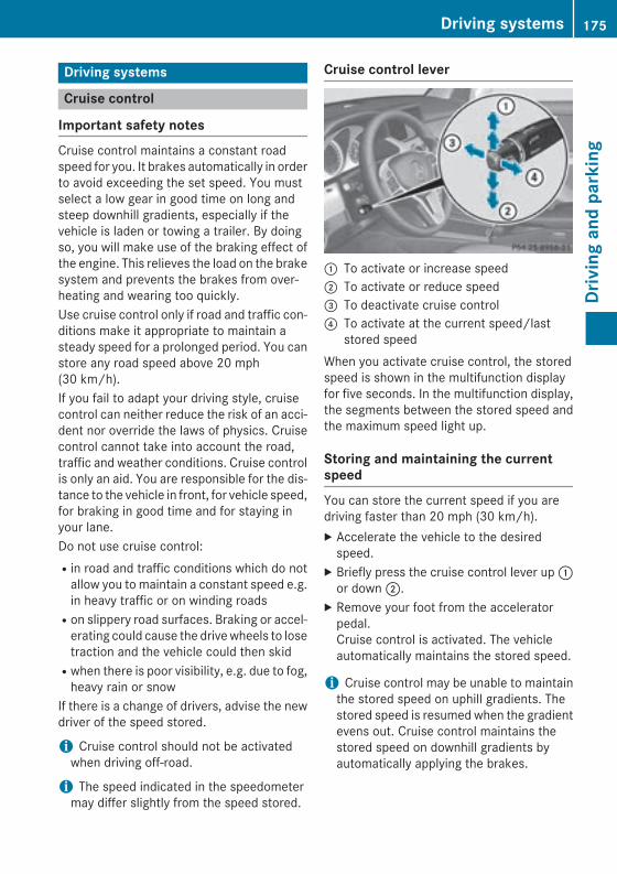
Driving systems
Cruise control
Important safety notesCruise control maintains a constant roadspeed for you. It brakes automatically in orderto avoid exceeding the set speed. You mustselect a low gear in good time on long andsteep downhill gradients, especially if thevehicle is laden or towing a trailer. By doingso, you will make use of the braking effect ofthe engine. This relieves the load on the brakesystem and prevents the brakes from over-heating and wearing too quickly.Use cruise control only if road and traffic con-ditions make it appropriate to maintain asteady speed for a prolonged period. You canstore any road speed above 20 mph(30 km/h).If you fail to adapt your driving style, cruisecontrol can neither reduce the risk of an acci-dent nor override the laws of physics. Cruisecontrol cannot take into account the road,traffic and weather conditions. Cruise controlis only an aid. You are responsible for the dis-tance to the vehicle in front, for vehicle speed,for braking in good time and for staying inyour lane.Do not use cruise control:Rin road and traffic conditions which do not
allow you to maintain a constant speed e.g.in heavy traffic or on winding roadsRon slippery road surfaces. Braking or accel-
erating could cause the drive wheels to losetraction and the vehicle could then skidRwhen there is poor visibility, e.g. due to fog,
heavy rain or snowIf there is a change of drivers, advise the newdriver of the speed stored.
i Cruise control should not be activatedwhen driving off-road.
i The speed indicated in the speedometermay differ slightly from the speed stored.
Cruise control lever
: To activate or increase speed; To activate or reduce speed= To deactivate cruise control? To activate at the current speed/last
stored speedWhen you activate cruise control, the storedspeed is shown in the multifunction displayfor five seconds. In the multifunction display,the segments between the stored speed andthe maximum speed light up.
Storing and maintaining the currentspeedYou can store the current speed if you aredriving faster than 20 mph (30 km/h).X Accelerate the vehicle to the desired
speed.X Briefly press the cruise control lever up :
or down ;.X Remove your foot from the accelerator
pedal.Cruise control is activated. The vehicleautomatically maintains the stored speed.
i Cruise control may be unable to maintainthe stored speed on uphill gradients. Thestored speed is resumed when the gradientevens out. Cruise control maintains thestored speed on downhill gradients byautomatically applying the brakes.
Driving systems 175
Driv
ing
and
park
ing
Z
Storing the current speed or calling upthe last stored speed
G WARNINGIf you call up the stored speed and it differsfrom the current speed, the vehicle acceler-ates or decelerates. If you do not know thestored speed, the vehicle could accelerate orbrake unexpectedly. There is a risk of an acci-dent.Pay attention to the road and traffic condi-tions before calling up the stored speed. If youdo not know the stored speed, store thedesired speed again.
X Briefly pull the cruise control lever towardsyou ?.
X Remove your foot from the acceleratorpedal.The first time cruise control is activated, itstores the current speed or regulates thespeed of the vehicle to the previouslystored speed.
Setting a speedKeep in mind that it may take a brief momentuntil the vehicle has accelerated or braked tothe speed set.X Press the cruise control lever up : for a
higher speed or down ; for a lower speed.X To adjust the set speed in 1 mph incre-
ments (1 km/h increments): brieflypress the cruise control lever up : ordown ; to the pressure point.Every time the cruise control lever ispressed up : or down ; the last speedstored is increased or reduced.
X To adjust the set speed in 5 mph incre-ments (10 km/h increments): brieflypress the cruise control lever up : ordown ; beyond the pressure point.Every time the cruise control lever ispressed up : or down ; the last speedstored is increased or reduced.
i Cruise control is not deactivated if youdepress the accelerator pedal. For exam-ple, if you accelerate briefly to overtake,cruise control adjusts the vehicle's speedto the last speed stored after you have fin-ished overtaking.
Deactivating cruise controlThere are several ways to deactivate cruisecontrol:X Briefly press the cruise control lever for-
wards =.orX Brake.Cruise control is automatically deactivated if:Ryou depress the parking brakeRyou are driving at less than 20 mph
(30 km/h)RESP® intervenes or you deactivate ESP®
Ryou shift the transmission to position Nwhile driving
If cruise control is deactivated, you will hear awarning tone. You will see the Cruise Con‐trol Off message in the multifunction dis-play for approximately five seconds.
i When you switch off the engine, the lastspeed stored is cleared.
DISTRONIC PLUS
Important safety notesDISTRONIC PLUS regulates the speed andautomatically helps you maintain the dis-tance to the vehicle detected in front.DISTRONIC PLUS brakes automatically sothat the set speed is not exceeded.You must select a low gear in good time onlong and steep downhill gradients, especiallyif the vehicle is laden or towing a trailer. Bydoing so, you will make use of the brakingeffect of the engine. This relieves the load onthe brake system and prevents the brakesfrom overheating and wearing too quickly.
176 Driving systemsDr
ivin
g an
d pa
rkin
g
If DISTRONIC PLUS detects a slower-movingvehicle in front, your vehicle is braked in orderto maintain the preset distance to the vehiclein front.
G WARNINGDISTRONIC PLUS does not react to:Rpeople or animalsRstationary obstacles on the road, e.g. stop-
ped or parked vehiclesRoncoming and crossing trafficAs a result, DISTRONIC PLUS may neither givewarnings nor intervene in such situations.There is a risk of an accident.Always pay careful attention to the traffic sit-uation and be ready to brake.
G WARNINGDISTRONIC PLUS cannot always clearly iden-tify other road users and complex traffic sit-uations.In such cases, DISTRONIC PLUS may:Rgive an unnecessary warning and then
brake the vehicleRneither give a warning nor interveneRaccelerate or brake unexpectedlyThere is a risk of an accident.Continue to drive carefully and be ready tobrake, in particular when warned to do so byDISTRONIC PLUS.
G WARNINGDISTRONIC PLUS brakes your vehicle with upto 40% of the maximum braking force. If thisbraking force is insufficient, DISTRONIC PLUSwarns you visually and audibly. There is a riskof an accident.In such cases, apply the brakes yourself andtry to take evasive action.
! If DISTRONIC PLUS or the HOLD functionis activated, the vehicle brakes automati-cally in certain situations. To prevent dam-age to the vehicle, deactivate DISTRONICPLUS and the HOLD function in the follow-ing or other similar situations:Rwhen towing the vehicleRin the car wash
If you fail to adapt your driving style,DISTRONIC PLUS can neither reduce the riskof accident nor override the laws of physics.DISTRONIC PLUS cannot take into accountthe road, traffic and weather conditions.DISTRONIC PLUS is only an aid. You areresponsible for the distance to the vehicle infront, for vehicle speed, for braking in goodtime and for staying in your lane.Do not use DISTRONIC PLUS:Rin road and traffic conditions which do not
allow you to maintain a constant speed e.g.in heavy traffic or on winding roadsRon slippery road surfaces. Braking or accel-
erating could cause the drive wheels to losetraction and the vehicle could then skidRwhen there is poor visibility, e.g. due to fog,
heavy rain or snowDISTRONIC PLUS may not detect narrowvehicles driving in front, e.g. motorcycles, orvehicles driving on a different line.In particular, the detection of obstacles canbe impaired if:Rthere is dirt on the sensors or anything else
covering the sensorsRthere is snow or heavy rainRthere is interference by other radar sourcesRthere are strong radar reflections, for
example, in parking garagesIf DISTRONIC PLUS no longer detects a vehi-cle in front, DISTRONIC PLUS may unexpect-edly accelerate the vehicle to the storedspeed.
Driving systems 177
Driv
ing
and
park
ing
Z
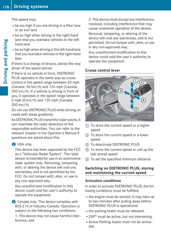
This speed may:Rbe too high if you are driving in a filter lane
or an exit laneRbe so high when driving in the right-hand
lane that you overtake vehicles in the left-hand laneRbe so high when driving in the left-hand lane
that you overtake vehicles in the right-handlane
If there is a change of drivers, advise the newdriver of the speed stored.If there is no vehicle in front, DISTRONICPLUS operates in the same way as cruisecontrol in the speed range between 20 mph(Canada: 30 km/h) and 120 mph (Canada:200 km/h). If a vehicle is driving in front ofyou, it operates in the speed range between0 mph (0 km/h) and 120 mph (Canada:200 km/h).Do not use DISTRONIC PLUS while driving onroads with steep gradients.As DISTRONIC PLUS transmits radar waves, itcan resemble the radar detectors of theresponsible authorities. You can refer to therelevant chapter in the Operator's Manual ifquestions are asked about this.
i USA only:This device has been approved by the FCCas a "Vehicular Radar System". The radarsensor is intended for use in an automotiveradar system only. Removing, tamperingwith, or altering the device will void anywarranties, and is not permitted by theFCC. Do not tamper with, alter, or use inany non-approved way.Any unauthorized modification to thisdevice could void the user’s authority tooperate the equipment.
i Canada only: This device complies withRSS-210 of Industry Canada. Operation issubject to the following two conditions:1. This device may not cause harmful inter-ference, and
2. This device must accept any interferencereceived, including interference that maycause undesired operation of the device.Removal, tampering, or altering of thedevice will void any warranties, and is notpermitted. Do not tamper with, alter, or usein any non-approved way.Any unauthorized modification to thisdevice could void the user's authority tooperate the equipment.
Cruise control lever
: To store the current speed or a higherspeed
; To store the current speed or a lowerspeed
= To deactivate DISTRONIC PLUS? To store the current speed or call up the
last stored speedA To set the specified minimum distance
Switching on DISTRONIC PLUS, storingand maintaining the current speed
Activation conditionsIn order to activate DISTRONIC PLUS, the fol-lowing conditions must be fulfilled:Rthe engine must be started. It may take up
to two minutes after pulling away beforeDISTRONIC PLUS is operational.Rthe parking brake must be released.RESP® must be active, but not intervening.RActive Parking Assist must not be activa-
ted.
178 Driving systemsDr
ivin
g an
d pa
rkin
g
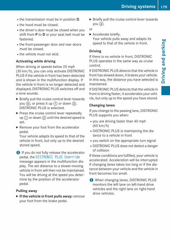
Rthe transmission must be in position D.Rthe hood must be closed.Rthe driver's door must be closed when you
shift from P to D or your seat belt must befastened.Rthe front-passenger door and rear doors
must be closed.Rthe vehicle must not skid.
Activating while drivingWhen driving at speeds below 20 mph(30 km/h), you can only activate DISTRONICPLUS if the vehicle in front has been detectedand is shown in the multifunction display. Ifthe vehicle in front is no longer detected anddisplayed, DISTRONIC PLUS switches off anda tone sounds.X Briefly pull the cruise control lever towards
you ?, or press it up : or down ;.DISTRONIC PLUS is selected.
X Press the cruise control lever repeatedlyup : or down ; until the desired speed isset.
X Remove your foot from the acceleratorpedal.Your vehicle adapts its speed to that of thevehicle in front, but only up to the desiredstored speed.
i If you do not fully release the acceleratorpedal, the DISTRONIC PLUS Overridemessage appears in the multifunction dis-play. The set distance to a slower-movingvehicle in front will then not be maintained.You will be driving at the speed you deter-mine by the position of the acceleratorpedal.
Pulling awayX If the vehicle in front pulls away: remove
your foot from the brake pedal.
X Briefly pull the cruise control lever towardsyou ?.
orX Accelerate briefly.
Your vehicle pulls away and adapts itsspeed to that of the vehicle in front.
DrivingIf there is no vehicle in front, DISTRONICPLUS operates in the same way as cruisecontrol.If DISTRONIC PLUS detects that the vehicle infront has slowed down, it brakes your vehicle.In this way, the distance you have selected ismaintained.If DISTRONIC PLUS detects that the vehicle infront is driving faster, it accelerates your vehi-cle, but only up to the speed you have stored.
Changing lanesIf you change to the passing lane, DISTRONICPLUS supports you when:Ryou are driving faster than 40 mph
(60 km/h)RDISTRONIC PLUS is maintaining the dis-
tance to a vehicle in frontRyou switch on the appropriate turn signalRDISTRONIC PLUS does not detect a danger
of collisionIf these conditions are fulfilled, your vehicle isaccelerated. Acceleration will be interruptedif changing lanes takes too long or if the dis-tance between your vehicle and the vehicle infront becomes too small.
i When changing lanes, DISTRONIC PLUSmonitors the left lane on left-hand drivevehicles and the right lane on right-handdrive vehicles.
Driving systems 179
Driv
ing
and
park
ing
Z
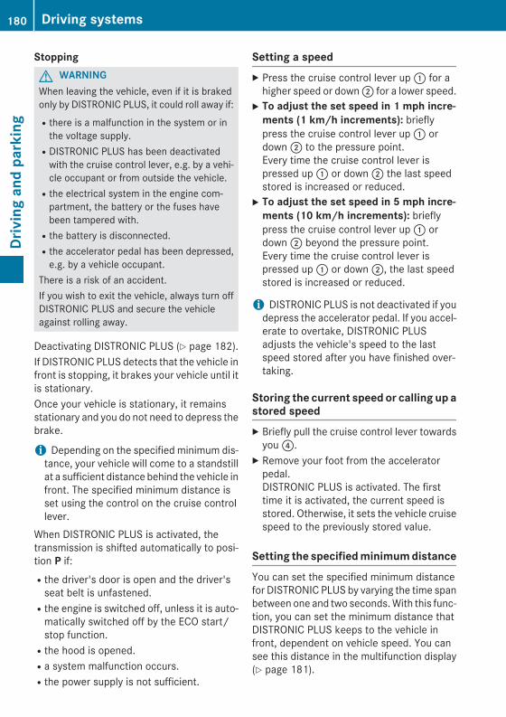
StoppingG WARNINGWhen leaving the vehicle, even if it is brakedonly by DISTRONIC PLUS, it could roll away if:Rthere is a malfunction in the system or in
the voltage supply.RDISTRONIC PLUS has been deactivated
with the cruise control lever, e.g. by a vehi-cle occupant or from outside the vehicle.Rthe electrical system in the engine com-
partment, the battery or the fuses havebeen tampered with.Rthe battery is disconnected.Rthe accelerator pedal has been depressed,
e.g. by a vehicle occupant.There is a risk of an accident.If you wish to exit the vehicle, always turn offDISTRONIC PLUS and secure the vehicleagainst rolling away.
Deactivating DISTRONIC PLUS (Y page 182).If DISTRONIC PLUS detects that the vehicle infront is stopping, it brakes your vehicle until itis stationary.Once your vehicle is stationary, it remainsstationary and you do not need to depress thebrake.
i Depending on the specified minimum dis-tance, your vehicle will come to a standstillat a sufficient distance behind the vehicle infront. The specified minimum distance isset using the control on the cruise controllever.
When DISTRONIC PLUS is activated, thetransmission is shifted automatically to posi-tion P if:Rthe driver's door is open and the driver's
seat belt is unfastened.Rthe engine is switched off, unless it is auto-
matically switched off by the ECO start/stop function.Rthe hood is opened.Ra system malfunction occurs.Rthe power supply is not sufficient.
Setting a speedX Press the cruise control lever up : for a
higher speed or down ; for a lower speed.X To adjust the set speed in 1 mph incre-
ments (1 km/h increments): brieflypress the cruise control lever up : ordown ; to the pressure point.Every time the cruise control lever ispressed up : or down ; the last speedstored is increased or reduced.
X To adjust the set speed in 5 mph incre-ments (10 km/h increments): brieflypress the cruise control lever up : ordown ; beyond the pressure point.Every time the cruise control lever ispressed up : or down ;, the last speedstored is increased or reduced.
i DISTRONIC PLUS is not deactivated if youdepress the accelerator pedal. If you accel-erate to overtake, DISTRONIC PLUSadjusts the vehicle's speed to the lastspeed stored after you have finished over-taking.
Storing the current speed or calling up astored speedX Briefly pull the cruise control lever towards
you ?.X Remove your foot from the accelerator
pedal.DISTRONIC PLUS is activated. The firsttime it is activated, the current speed isstored. Otherwise, it sets the vehicle cruisespeed to the previously stored value.
Setting the specified minimum distanceYou can set the specified minimum distancefor DISTRONIC PLUS by varying the time spanbetween one and two seconds. With this func-tion, you can set the minimum distance thatDISTRONIC PLUS keeps to the vehicle infront, dependent on vehicle speed. You cansee this distance in the multifunction display(Y page 181).
180 Driving systemsDr
ivin
g an
d pa
rkin
g
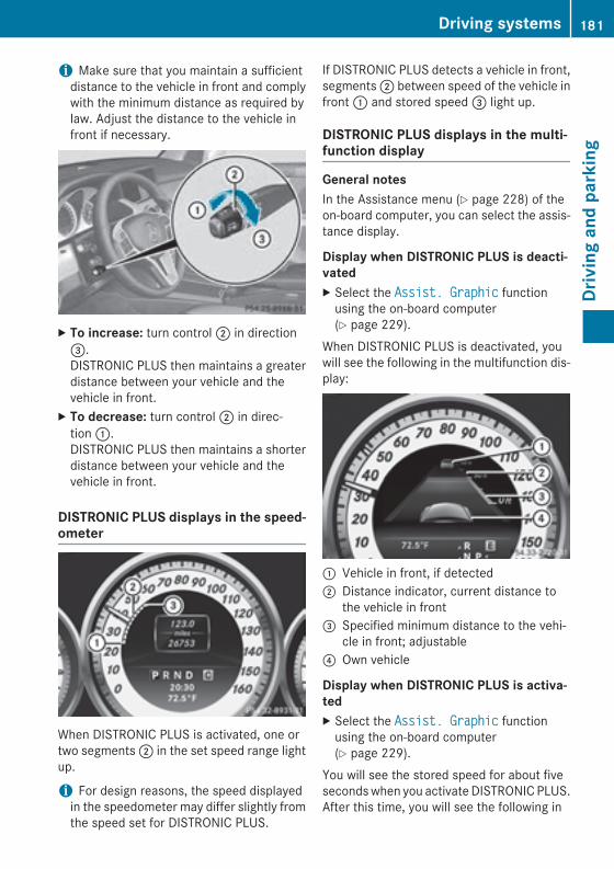
i Make sure that you maintain a sufficientdistance to the vehicle in front and complywith the minimum distance as required bylaw. Adjust the distance to the vehicle infront if necessary.
X To increase: turn control ; in direction=.DISTRONIC PLUS then maintains a greaterdistance between your vehicle and thevehicle in front.
X To decrease: turn control ; in direc-tion :.DISTRONIC PLUS then maintains a shorterdistance between your vehicle and thevehicle in front.
DISTRONIC PLUS displays in the speed-ometer
When DISTRONIC PLUS is activated, one ortwo segments ; in the set speed range lightup.
i For design reasons, the speed displayedin the speedometer may differ slightly fromthe speed set for DISTRONIC PLUS.
If DISTRONIC PLUS detects a vehicle in front,segments ; between speed of the vehicle infront : and stored speed = light up.
DISTRONIC PLUS displays in the multi-function display
General notesIn the Assistance menu (Y page 228) of theon-board computer, you can select the assis-tance display.
Display when DISTRONIC PLUS is deacti-vatedX Select the Assist. Graphic function
using the on-board computer(Y page 229).
When DISTRONIC PLUS is deactivated, youwill see the following in the multifunction dis-play:
: Vehicle in front, if detected; Distance indicator, current distance to
the vehicle in front= Specified minimum distance to the vehi-
cle in front; adjustable? Own vehicle
Display when DISTRONIC PLUS is activa-tedX Select the Assist. Graphic function
using the on-board computer(Y page 229).
You will see the stored speed for about fiveseconds when you activate DISTRONIC PLUS.After this time, you will see the following in
Driving systems 181
Driv
ing
and
park
ing
Z
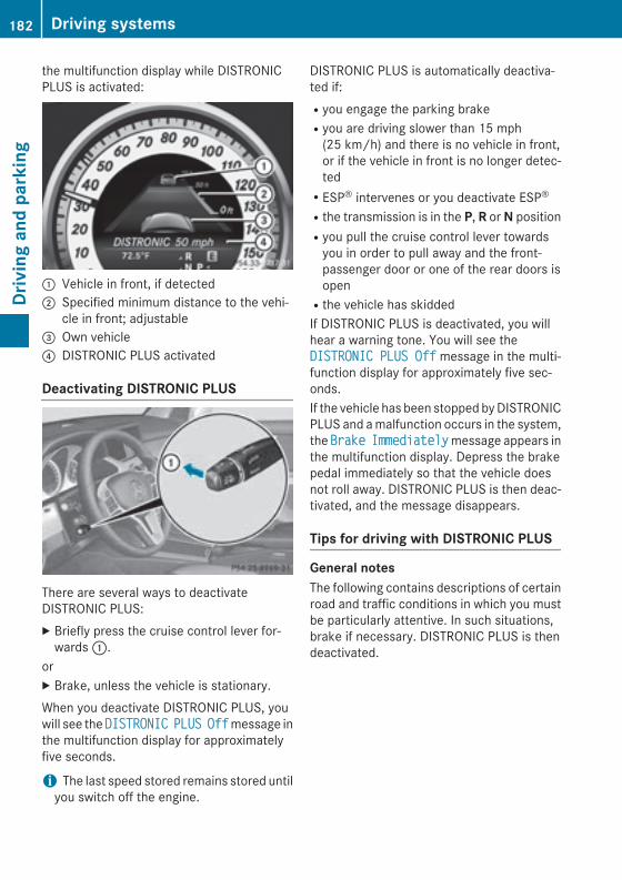
the multifunction display while DISTRONICPLUS is activated:
: Vehicle in front, if detected; Specified minimum distance to the vehi-
cle in front; adjustable= Own vehicle? DISTRONIC PLUS activated
Deactivating DISTRONIC PLUS
There are several ways to deactivateDISTRONIC PLUS:X Briefly press the cruise control lever for-
wards :.orX Brake, unless the vehicle is stationary.When you deactivate DISTRONIC PLUS, youwill see the DISTRONIC PLUS Off message inthe multifunction display for approximatelyfive seconds.
i The last speed stored remains stored untilyou switch off the engine.
DISTRONIC PLUS is automatically deactiva-ted if:Ryou engage the parking brakeRyou are driving slower than 15 mph
(25 km/h) and there is no vehicle in front,or if the vehicle in front is no longer detec-tedRESP® intervenes or you deactivate ESP®
Rthe transmission is in the P, R or N positionRyou pull the cruise control lever towards
you in order to pull away and the front-passenger door or one of the rear doors isopenRthe vehicle has skiddedIf DISTRONIC PLUS is deactivated, you willhear a warning tone. You will see theDISTRONIC PLUS Off message in the multi-function display for approximately five sec-onds.If the vehicle has been stopped by DISTRONICPLUS and a malfunction occurs in the system,the Brake Immediately message appears inthe multifunction display. Depress the brakepedal immediately so that the vehicle doesnot roll away. DISTRONIC PLUS is then deac-tivated, and the message disappears.
Tips for driving with DISTRONIC PLUS
General notesThe following contains descriptions of certainroad and traffic conditions in which you mustbe particularly attentive. In such situations,brake if necessary. DISTRONIC PLUS is thendeactivated.
182 Driving systemsDr
ivin
g an
d pa
rkin
g
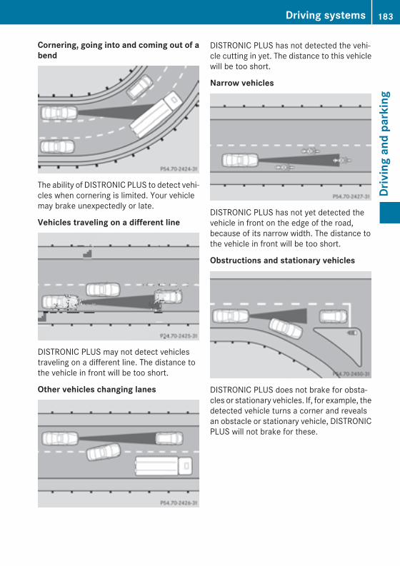
Cornering, going into and coming out of abend
The ability of DISTRONIC PLUS to detect vehi-cles when cornering is limited. Your vehiclemay brake unexpectedly or late.
Vehicles traveling on a different line
DISTRONIC PLUS may not detect vehiclestraveling on a different line. The distance tothe vehicle in front will be too short.
Other vehicles changing lanes
DISTRONIC PLUS has not detected the vehi-cle cutting in yet. The distance to this vehiclewill be too short.
Narrow vehicles
DISTRONIC PLUS has not yet detected thevehicle in front on the edge of the road,because of its narrow width. The distance tothe vehicle in front will be too short.
Obstructions and stationary vehicles
DISTRONIC PLUS does not brake for obsta-cles or stationary vehicles. If, for example, thedetected vehicle turns a corner and revealsan obstacle or stationary vehicle, DISTRONICPLUS will not brake for these.
Driving systems 183
Driv
ing
and
park
ing
Z
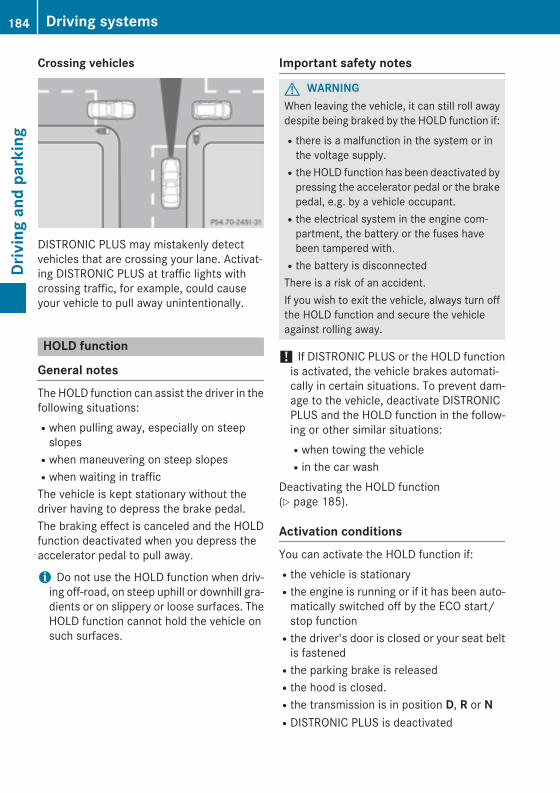
Crossing vehicles
DISTRONIC PLUS may mistakenly detectvehicles that are crossing your lane. Activat-ing DISTRONIC PLUS at traffic lights withcrossing traffic, for example, could causeyour vehicle to pull away unintentionally.
HOLD function
General notesThe HOLD function can assist the driver in thefollowing situations:Rwhen pulling away, especially on steep
slopesRwhen maneuvering on steep slopesRwhen waiting in trafficThe vehicle is kept stationary without thedriver having to depress the brake pedal.The braking effect is canceled and the HOLDfunction deactivated when you depress theaccelerator pedal to pull away.
i Do not use the HOLD function when driv-ing off-road, on steep uphill or downhill gra-dients or on slippery or loose surfaces. TheHOLD function cannot hold the vehicle onsuch surfaces.
Important safety notes
G WARNINGWhen leaving the vehicle, it can still roll awaydespite being braked by the HOLD function if:Rthere is a malfunction in the system or in
the voltage supply.Rthe HOLD function has been deactivated by
pressing the accelerator pedal or the brakepedal, e.g. by a vehicle occupant.Rthe electrical system in the engine com-
partment, the battery or the fuses havebeen tampered with.Rthe battery is disconnectedThere is a risk of an accident.If you wish to exit the vehicle, always turn offthe HOLD function and secure the vehicleagainst rolling away.
! If DISTRONIC PLUS or the HOLD functionis activated, the vehicle brakes automati-cally in certain situations. To prevent dam-age to the vehicle, deactivate DISTRONICPLUS and the HOLD function in the follow-ing or other similar situations:Rwhen towing the vehicleRin the car wash
Deactivating the HOLD function(Y page 185).
Activation conditionsYou can activate the HOLD function if:Rthe vehicle is stationaryRthe engine is running or if it has been auto-
matically switched off by the ECO start/stop functionRthe driver's door is closed or your seat belt
is fastenedRthe parking brake is releasedRthe hood is closed.Rthe transmission is in position D, R or NRDISTRONIC PLUS is deactivated
184 Driving systemsDr
ivin
g an
d pa
rkin
g
Activating the HOLD functionX Make sure that the activation conditions
are met.X Depress the brake pedal.X Quickly depress the brake pedal further
until ë appears in the multifunction dis-play.The HOLD function is activated. You canrelease the brake pedal.
i If depressing the brake pedal the firsttime does not activate the HOLD function,wait briefly and then try again.
Deactivating the HOLD functionThe HOLD function is deactivated automati-cally if:Ryou accelerate and the transmission is in
position D or R.Rthe transmission is in position P.Ryou depress the brake pedal again with a
certain amount of pressure until ë dis-appears from the multifunction display.Ryou activate DISTRONIC PLUS.When the HOLD function is activated in vehi-cles with an automatic transmission, thetransmission is shifted automatically to posi-tion P if:Rthe driver's door is open and the driver's
seat belt is unfastened.Rthe engine is switched off, unless it is auto-
matically switched off by the ECO start/stop function.Rthe hood is opened.Ra system malfunction occurs.Rthe power supply is not sufficient.The horn will also sound at regular intervals ifthe HOLD function is activated and you:Rswitch the engine off, open the driver's
door and remove your seat belt.Ropen the hood.The sounding of the horn alerts you to the factthat the vehicle has been parked while the
HOLD function is still activated. If you attemptto lock the vehicle, the tone becomes louder.The vehicle is not locked until the HOLD func-tion is deactivated.
i If the engine has been switched off, itcannot be started again until the HOLDfunction has been deactivated.
If there is a malfunction in the system orpower supply while the HOLD function is acti-vated, the Brake Immediately message isshown in the multifunction display. Immedi-ately depress the brake firmly until the warn-ing message in the multifunction display goesout.You can also shift the transmission to positionP. This deactivates the HOLD function.
4MATIC (permanent four-wheel drive)4MATIC ensures that all four wheels are per-manently driven. Together with ESP® andETS, it improves the traction of your vehiclewhenever a drive wheel spins due to insuffi-cient grip.If you fail to adapt your driving style, 4MATICcan neither reduce the risk of accident noroverride the laws of physics. 4MATIC cannottake account of road, weather and traffic con-ditions. 4MATIC is only an aid. You areresponsible for the distance to the vehicle infront, for vehicle speed, for braking in goodtime and for staying in your lane.If a drive wheel spins due to insufficient grip:ROnly depress the accelerator pedal as far as
necessary when pulling away.RAccelerate less when driving.
! Never tow the vehicle with one axleraised. This may damage the transfer case.Damage of this sort is not covered by theMercedes-Benz Limited Warranty. Allwheels must remain either on the ground orbe fully raised. Observe the instructions fortowing the vehicle with all wheels in fullcontact with the ground.
Driving systems 185
Driv
ing
and
park
ing
Z
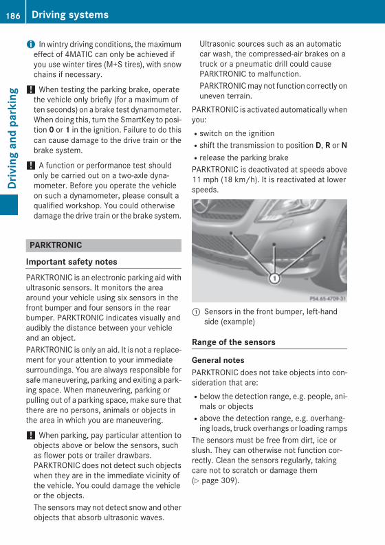
i In wintry driving conditions, the maximumeffect of 4MATIC can only be achieved ifyou use winter tires (M+S tires), with snowchains if necessary.
! When testing the parking brake, operatethe vehicle only briefly (for a maximum often seconds) on a brake test dynamometer.When doing this, turn the SmartKey to posi-tion 0 or 1 in the ignition. Failure to do thiscan cause damage to the drive train or thebrake system.
! A function or performance test shouldonly be carried out on a two-axle dyna-mometer. Before you operate the vehicleon such a dynamometer, please consult aqualified workshop. You could otherwisedamage the drive train or the brake system.
PARKTRONIC
Important safety notesPARKTRONIC is an electronic parking aid withultrasonic sensors. It monitors the areaaround your vehicle using six sensors in thefront bumper and four sensors in the rearbumper. PARKTRONIC indicates visually andaudibly the distance between your vehicleand an object.PARKTRONIC is only an aid. It is not a replace-ment for your attention to your immediatesurroundings. You are always responsible forsafe maneuvering, parking and exiting a park-ing space. When maneuvering, parking orpulling out of a parking space, make sure thatthere are no persons, animals or objects inthe area in which you are maneuvering.
! When parking, pay particular attention toobjects above or below the sensors, suchas flower pots or trailer drawbars.PARKTRONIC does not detect such objectswhen they are in the immediate vicinity ofthe vehicle. You could damage the vehicleor the objects.The sensors may not detect snow and otherobjects that absorb ultrasonic waves.
Ultrasonic sources such as an automaticcar wash, the compressed-air brakes on atruck or a pneumatic drill could causePARKTRONIC to malfunction.PARKTRONIC may not function correctly onuneven terrain.
PARKTRONIC is activated automatically whenyou:Rswitch on the ignitionRshift the transmission to position D, R or NRrelease the parking brakePARKTRONIC is deactivated at speeds above11 mph (18 km/h). It is reactivated at lowerspeeds.
: Sensors in the front bumper, left-handside (example)
Range of the sensors
General notesPARKTRONIC does not take objects into con-sideration that are:Rbelow the detection range, e.g. people, ani-
mals or objectsRabove the detection range, e.g. overhang-
ing loads, truck overhangs or loading rampsThe sensors must be free from dirt, ice orslush. They can otherwise not function cor-rectly. Clean the sensors regularly, takingcare not to scratch or damage them(Y page 309).
186 Driving systemsDr
ivin
g an
d pa
rkin
g

Side view
Top view
Front sensors
Center Approx. 40 in (approx.100 cm)
Corners Approx. 24 in (approx.60 cm)
Rear sensors
Center Approx. 48 in (approx.120 cm)
Corners Approx. 32 in (approx.80 cm)
Minimum distance
Center Approx. 8 in (approx.20 cm)
Corners Approx. 6 in (approx.15 cm)
If there is an obstacle within this range, therelevant warning displays light up and a warn-
ing tone sounds. If the distance falls belowthe minimum, the distance may no longer beshown.
Warning displaysThe warning displays show the distancebetween the sensors and the obstacle. Thewarning display for the front area is locatedon the dashboard above the center air vents.The warning display for the rear area is loca-ted on the headliner in the rear compartment.
Warning display for the front area: Segments on the left-hand side of the
vehicle; Segments on the right-hand side of the
vehicle= Segments showing operational readinessThe warning display for each side of the vehi-cle is divided into five yellow and two red seg-ments. PARKTRONIC is operational if yellowsegments showing operational readiness =light up.The selected transmission position and thedirection in which the vehicle is rolling deter-mine which warning display is active when theengine is running.
Driving systems 187
Driv
ing
and
park
ing
Z
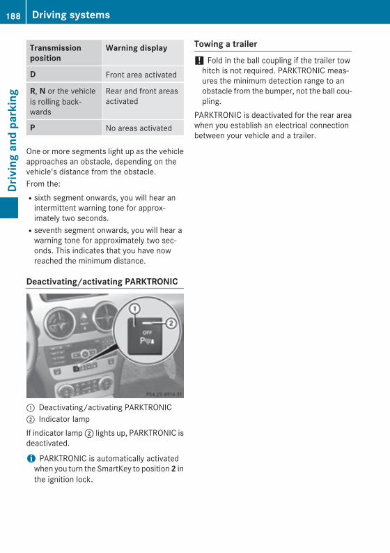
Transmission position
Warning display
D Front area activated
R, N or the vehicleis rolling back-wards
Rear and front areasactivated
P No areas activated
One or more segments light up as the vehicleapproaches an obstacle, depending on thevehicle's distance from the obstacle.From the:Rsixth segment onwards, you will hear an
intermittent warning tone for approx-imately two seconds.Rseventh segment onwards, you will hear a
warning tone for approximately two sec-onds. This indicates that you have nowreached the minimum distance.
Deactivating/activating PARKTRONIC
: Deactivating/activating PARKTRONIC; Indicator lampIf indicator lamp ; lights up, PARKTRONIC isdeactivated.
i PARKTRONIC is automatically activatedwhen you turn the SmartKey to position 2 inthe ignition lock.
Towing a trailer
! Fold in the ball coupling if the trailer towhitch is not required. PARKTRONIC meas-ures the minimum detection range to anobstacle from the bumper, not the ball cou-pling.
PARKTRONIC is deactivated for the rear areawhen you establish an electrical connectionbetween your vehicle and a trailer.
188 Driving systemsDr
ivin
g an
d pa
rkin
g

Problems with PARKTRONIC
Problem Possible causes/consequences and M Solutions
Only the red segmentsin the PARKTRONICwarning displays are lit.You also hear a warningtone for approximatelytwo seconds.PARKTRONIC is deacti-vated after approx-imately five seconds,and the indicator lampin the PARKTRONICbutton lights up.
PARKTRONIC has malfunctioned and has switched off.X If problems persist, have PARKTRONIC checked at a qualified
specialist workshop.
Only the red segmentsin the PARKTRONICwarning displays are lit.PARKTRONIC is deacti-vated after approx-imately five seconds.
The PARKTRONIC sensors are dirty or there is interference.X Clean the PARKTRONIC sensors (Y page 309).X Switch the ignition back on.
The problem may be caused by an external source of radio orultrasound waves.X See if PARKTRONIC functions in a different location.
Active Parking Assist
Important safety notesActive Parking Assist is an electronic parkingaid with ultrasound. Ultrasound is used tomeasure the road on both sides of the vehicle.A parking symbol indicates a suitable parkingspace. Active steering intervention can assistyou during parking. You may also usePARKTRONIC (Y page 186).
G WARNINGWhile parking or pulling out of a parkingspace, the vehicle swings out and can driveonto areas of the oncoming lane. This couldresult in a collision with another road user.There is a risk of an accident.Pay attention to other road users. Stop thevehicle if necessary or cancel the Active Park-ing Assist parking procedure.
! If unavoidable, you should drive overobstacles such as curbs slowly and not at asharp angle. Otherwise, you may damagethe wheels or tires.
Active Parking Assist is merely an aid. It is nota replacement for your attention to yourimmediate surroundings. You are alwaysresponsible for safe maneuvering, parkingand exiting a parking space. Make sure thatno persons, animals or objects are in themaneuvering range.When PARKTRONIC is switched off, ActiveParking Assist is also unavailable.Active Parking Assist may possibly indicateparking spaces which are not suitable forparking, for example:Rwhere parking or stopping is prohibitedRin front of driveways or entrances and exitsRon unsuitable surfaces
Driving systems 189
Driv
ing
and
park
ing
Z
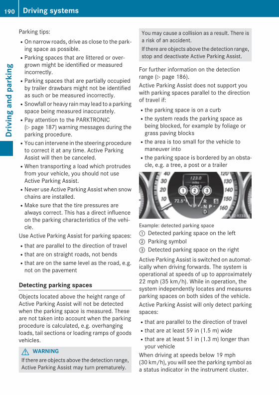
Parking tips:ROn narrow roads, drive as close to the park-
ing space as possible.RParking spaces that are littered or over-
grown might be identified or measuredincorrectly.RParking spaces that are partially occupied
by trailer drawbars might not be identifiedas such or be measured incorrectly.RSnowfall or heavy rain may lead to a parking
space being measured inaccurately.RPay attention to the PARKTRONIC
(Y page 187) warning messages during theparking procedure.RYou can intervene in the steering procedure
to correct it at any time. Active ParkingAssist will then be canceled.RWhen transporting a load which protrudes
from your vehicle, you should not useActive Parking Assist.RNever use Active Parking Assist when snow
chains are installed.RMake sure that the tire pressures are
always correct. This has a direct influenceon the parking characteristics of the vehi-cle.
Use Active Parking Assist for parking spaces:Rthat are parallel to the direction of travelRthat are on straight roads, not bendsRthat are on the same level as the road, e.g.
not on the pavement
Detecting parking spacesObjects located above the height range ofActive Parking Assist will not be detectedwhen the parking space is measured. Theseare not taken into account when the parkingprocedure is calculated, e.g. overhangingloads, tail sections or loading ramps of goodsvehicles.
G WARNINGIf there are objects above the detection range,Active Parking Assist may turn prematurely.
You may cause a collision as a result. There isa risk of an accident.If there are objects above the detection range,stop and deactivate Active Parking Assist.
For further information on the detectionrange (Y page 186).Active Parking Assist does not support youwith parking spaces parallel to the directionof travel if:Rthe parking space is on a curbRthe system reads the parking space as
being blocked, for example by foliage orgrass paving blocksRthe area is too small for the vehicle to
maneuver intoRthe parking space is bordered by an obsta-
cle, e.g. a tree, a post or a trailer
Example: detected parking space: Detected parking space on the left; Parking symbol= Detected parking space on the rightActive Parking Assist is switched on automat-ically when driving forwards. The system isoperational at speeds of up to approximately22 mph (35 km/h). While in operation, thesystem independently locates and measuresparking spaces on both sides of the vehicle.Active Parking Assist will only detect parkingspaces:Rthat are parallel to the direction of travelRthat are at least 59 in (1.5 m) wideRthat are at least 51 in (1.3 m) longer than
your vehicleWhen driving at speeds below 19 mph(30 km/h), you will see the parking symbol asa status indicator in the instrument cluster.
190 Driving systemsDr
ivin
g an
d pa
rkin
g
When a parking space has been detected, anarrow towards the right or the left alsoappears. By default, Active Parking Assistonly displays parking spaces on the front-passenger side. Parking spaces on the driv-er's side are displayed as soon as the turnsignal on the driver's side is activated. Whenparking on the driver's side, this must remainswitched on until you acknowledge the use ofActive Parking Assist by pressing the abutton on the multifunction steering wheel.A parking space is displayed while you aredriving past it, and until you are approx-imately 50 ft (15 m) away from it.
Parking
G WARNINGActive Parking Assist merely aids you by inter-vening actively in the steering. If you do notbrake there is a risk of an accident.Always apply the brakes yourself whenmaneuvering and parking.
X Stop the vehicle when the parking spacesymbol shows the desired parking space inthe instrument cluster.
X Shift the transmission to position R.The Start Park Assist? Yes: OK No:% message appears in the multifunctiondisplay.
X To cancel the procedure: press the %button on the multifunction steering wheelor pull away.
orX To park using Active Parking Assist:
press the a button on the multifunctionsteering wheel.The Park Assist Active Accelerate and Brake Observe Surroundings mes-sage appears in the multifunction display.
X Let go of the multifunction steering wheel.X Back up the vehicle, being ready to brake at
all times. When backing up, drive at a speedbelow approximately 6 mph (10 km/h).
Otherwise Active Parking Assist will be can-celed.
i In tight parking spaces, you will achievethe best parking results by backing up asfar as possible. When doing so, alsoobserve the PARKTRONIC messages.
X Stop as soon as PARKTRONIC sounds thecontinuous warning tone, if not before.Maneuvering may be required in tight park-ing spaces.
The Park Assist Active Select D Observe Surroundings message appears inthe multifunction display.X Shift the transmission to position D while
the vehicle is stationary.Active Parking Assist immediately steers inthe other direction.The Park Assist Active Accelerate and Brake Observe Surroundings mes-sage appears in the multifunction display.
i You will achieve the best results by wait-ing for the steering procedure to completebefore pulling away.
X Drive forwards and be ready to brake at alltimes.
X Stop as soon as PARKTRONIC sounds thecontinuous warning tone, if not before.
The Park Assist Active Select R Observe Surroundings message appears inthe multifunction display.X Further transmission shifts may be neces-
sary.As soon as the parking procedure is com-plete, the Park Assist Disabled messageappears and a warning tone sounds. ActiveParking Assist no longer supports you withsteering interventions. When Active ParkingAssist is finished, you must steer again your-self. PARKTRONIC is still available.X Maneuver if necessary.X Always observe the warning messages dis-
played by PARKTRONIC (Y page 187).
Driving systems 191
Driv
ing
and
park
ing
Z
Parking tips:RThe way your vehicle is positioned in the
parking space after parking is dependenton various factors. These include the posi-tion and shape of the vehicles parked infront and behind it and the conditions of thelocation. It may be the case that ActiveParking Assist guides you too far into aparking space, or not far enough into it. Insome cases, it may also lead you across oronto the curb. If necessary, you should can-cel the parking procedure with Active Park-ing Assist.RYou can also select preselect transmission
position D. The vehicle redirects and doesnot drive as far into the parking space.Should a gear be changed too early, theparking procedure will be canceled. A sen-sible parking position can no longer be ach-ieved from this position.
Exiting a parking spaceIn order that Active Parking Assist can sup-port you when you exit the parking space:Rthe border of the parking space must be
high enough at the front and the rear. Acurb is too small, for example.Rthe border of the parking space must not be
too wide, as the position of the vehicle mustnot exceed an angle of 45° to the startingposition as it is maneuvering into the park-ing space.Ra maneuvering distance of at least 3.3 ft
(1.0 m) must be available.X Start the engine.X Release the parking brake.X Switch on the turn signal on the side facing
the street.X Shift the transmission to position D or R.
The Start Park Assist? Yes: OK No:% message appears in the multifunctiondisplay.
X To cancel the procedure: press the %button on the multifunction steering wheelor pull away.
orX To exit a parking space using Active
Parking Assist: press the a button onthe multifunction steering wheel.The Park Assist Active Accelerate and Brake Observe Surroundings mes-sage appears in the multifunction display.
X Let go of the multifunction steering wheel.X Reverse the vehicle or drive forwards, being
ready to brake at all times. Do not exceed amaximum speed of approximately 6 mph(10 km/h) when exiting a parking space.Otherwise Active Parking Assist will be can-celed.
X Stop when PARKTRONIC sounds the con-tinuous warning tone, if not before.
X Shift the transmission to position D or R asrequired while the vehicle is stationary.Active Parking Assist immediately steers inthe other direction. The Park Assist Active Accelerate and Brake Observe Surroundings message appearsin the multifunction display.
i You will achieve the best results by wait-ing for the steering procedure to completebefore pulling away.If you back up after activation, the steeringwheel is moved to the straight-ahead posi-tion.
X Drive forwards or back up the vehicle, beingready to brake at all times.
X Stop as soon as PARKTRONIC sounds thecontinuous warning tone, if not before.
X Drive forwards and back up as prompted bythe PARKTRONIC warning displays, severaltimes if necessary.
Once you have exited the parking space com-pletely, the steering wheel is moved to thestraight-ahead position. You hear a tone andthe Park Assist Finished messageappears in the multifunction display. You will
192 Driving systemsDr
ivin
g an
d pa
rkin
g
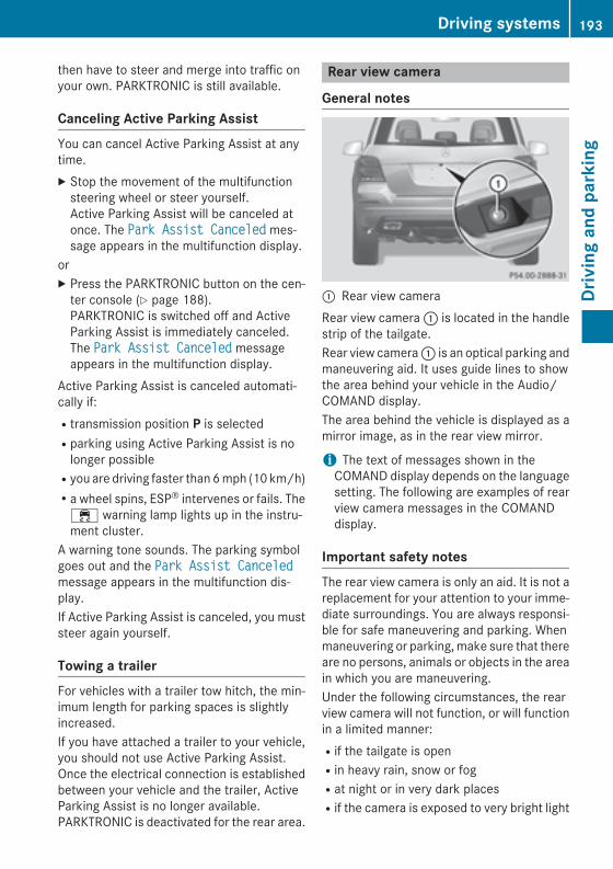
then have to steer and merge into traffic onyour own. PARKTRONIC is still available.
Canceling Active Parking AssistYou can cancel Active Parking Assist at anytime.X Stop the movement of the multifunction
steering wheel or steer yourself.Active Parking Assist will be canceled atonce. The Park Assist Canceled mes-sage appears in the multifunction display.
orX Press the PARKTRONIC button on the cen-
ter console (Y page 188).PARKTRONIC is switched off and ActiveParking Assist is immediately canceled.The Park Assist Canceled messageappears in the multifunction display.
Active Parking Assist is canceled automati-cally if:Rtransmission position P is selectedRparking using Active Parking Assist is no
longer possibleRyou are driving faster than 6 mph (10 km/h)Ra wheel spins, ESP® intervenes or fails. The
÷ warning lamp lights up in the instru-ment cluster.
A warning tone sounds. The parking symbolgoes out and the Park Assist Canceledmessage appears in the multifunction dis-play.If Active Parking Assist is canceled, you muststeer again yourself.
Towing a trailerFor vehicles with a trailer tow hitch, the min-imum length for parking spaces is slightlyincreased.If you have attached a trailer to your vehicle,you should not use Active Parking Assist.Once the electrical connection is establishedbetween your vehicle and the trailer, ActiveParking Assist is no longer available.PARKTRONIC is deactivated for the rear area.
Rear view camera
General notes
: Rear view cameraRear view camera : is located in the handlestrip of the tailgate.Rear view camera : is an optical parking andmaneuvering aid. It uses guide lines to showthe area behind your vehicle in the Audio/COMAND display.The area behind the vehicle is displayed as amirror image, as in the rear view mirror.
i The text of messages shown in theCOMAND display depends on the languagesetting. The following are examples of rearview camera messages in the COMANDdisplay.
Important safety notesThe rear view camera is only an aid. It is not areplacement for your attention to your imme-diate surroundings. You are always responsi-ble for safe maneuvering and parking. Whenmaneuvering or parking, make sure that thereare no persons, animals or objects in the areain which you are maneuvering.Under the following circumstances, the rearview camera will not function, or will functionin a limited manner:Rif the tailgate is openRin heavy rain, snow or fogRat night or in very dark placesRif the camera is exposed to very bright light
Driving systems 193
Driv
ing
and
park
ing
Z
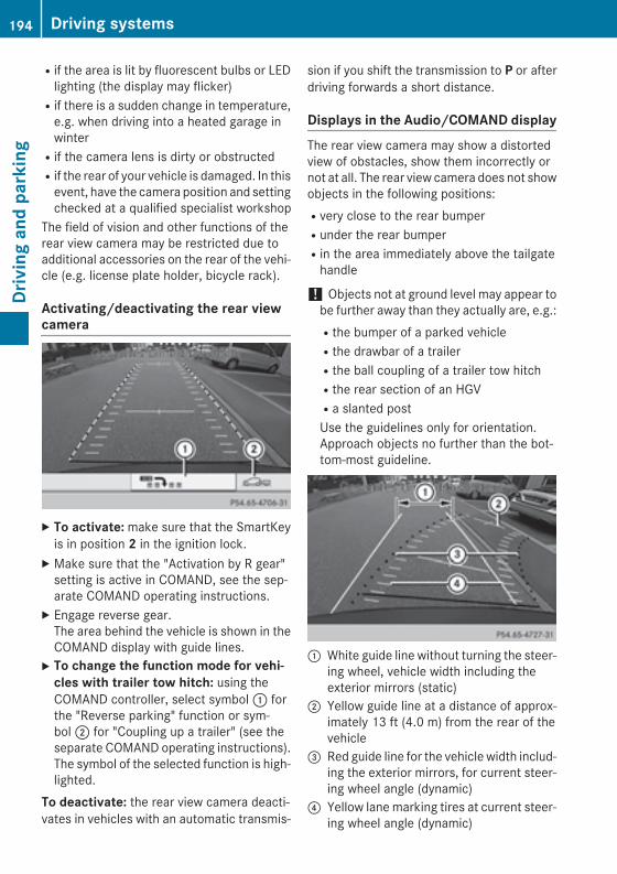
Rif the area is lit by fluorescent bulbs or LEDlighting (the display may flicker)Rif there is a sudden change in temperature,
e.g. when driving into a heated garage inwinterRif the camera lens is dirty or obstructedRif the rear of your vehicle is damaged. In this
event, have the camera position and settingchecked at a qualified specialist workshop
The field of vision and other functions of therear view camera may be restricted due toadditional accessories on the rear of the vehi-cle (e.g. license plate holder, bicycle rack).
Activating/deactivating the rear viewcamera
X To activate: make sure that the SmartKeyis in position 2 in the ignition lock.
X Make sure that the "Activation by R gear"setting is active in COMAND, see the sep-arate COMAND operating instructions.
X Engage reverse gear.The area behind the vehicle is shown in theCOMAND display with guide lines.
X To change the function mode for vehi-cles with trailer tow hitch: using theCOMAND controller, select symbol : forthe "Reverse parking" function or sym-bol ; for "Coupling up a trailer" (see theseparate COMAND operating instructions).The symbol of the selected function is high-lighted.
To deactivate: the rear view camera deacti-vates in vehicles with an automatic transmis-
sion if you shift the transmission to P or afterdriving forwards a short distance.
Displays in the Audio/COMAND displayThe rear view camera may show a distortedview of obstacles, show them incorrectly ornot at all. The rear view camera does not showobjects in the following positions:Rvery close to the rear bumperRunder the rear bumperRin the area immediately above the tailgate
handle
! Objects not at ground level may appear tobe further away than they actually are, e.g.:Rthe bumper of a parked vehicleRthe drawbar of a trailerRthe ball coupling of a trailer tow hitchRthe rear section of an HGVRa slanted postUse the guidelines only for orientation.Approach objects no further than the bot-tom-most guideline.
: White guide line without turning the steer-ing wheel, vehicle width including theexterior mirrors (static)
; Yellow guide line at a distance of approx-imately 13 ft (4.0 m) from the rear of thevehicle
= Red guide line for the vehicle width includ-ing the exterior mirrors, for current steer-ing wheel angle (dynamic)
? Yellow lane marking tires at current steer-ing wheel angle (dynamic)
194 Driving systemsDr
ivin
g an
d pa
rkin
g
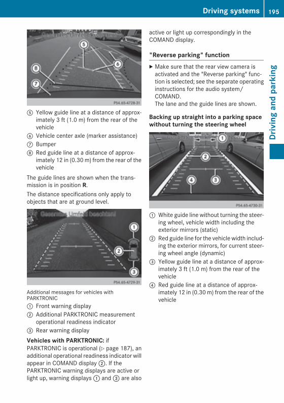
A Yellow guide line at a distance of approx-imately 3 ft (1.0 m) from the rear of thevehicle
B Vehicle center axle (marker assistance)C BumperD Red guide line at a distance of approx-
imately 12 in (0.30 m) from the rear of thevehicle
The guide lines are shown when the trans-mission is in position R.The distance specifications only apply toobjects that are at ground level.
Additional messages for vehicles withPARKTRONIC: Front warning display; Additional PARKTRONIC measurement
operational readiness indicator= Rear warning displayVehicles with PARKTRONIC: ifPARKTRONIC is operational (Y page 187), anadditional operational readiness indicator willappear in COMAND display ;. If thePARKTRONIC warning displays are active orlight up, warning displays : and = are also
active or light up correspondingly in theCOMAND display.
"Reverse parking" functionX Make sure that the rear view camera is
activated and the "Reverse parking" func-tion is selected; see the separate operatinginstructions for the audio system/COMAND.The lane and the guide lines are shown.
Backing up straight into a parking spacewithout turning the steering wheel
: White guide line without turning the steer-ing wheel, vehicle width including theexterior mirrors (static)
; Red guide line for the vehicle width includ-ing the exterior mirrors, for current steer-ing wheel angle (dynamic)
= Yellow guide line at a distance of approx-imately 3 ft (1.0 m) from the rear of thevehicle
? Red guide line at a distance of approx-imately 12 in (0.30 m) from the rear of thevehicle
Driving systems 195
Driv
ing
and
park
ing
Z
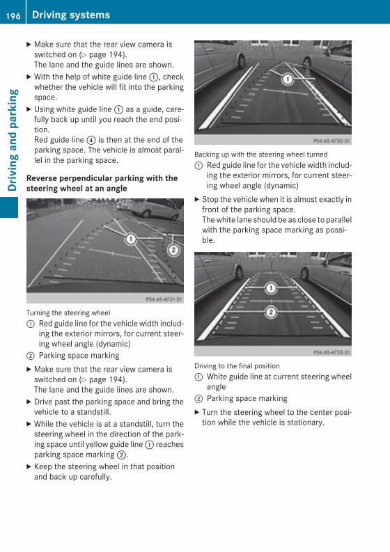
X Make sure that the rear view camera isswitched on (Y page 194).The lane and the guide lines are shown.
X With the help of white guide line :, checkwhether the vehicle will fit into the parkingspace.
X Using white guide line : as a guide, care-fully back up until you reach the end posi-tion.Red guide line ? is then at the end of theparking space. The vehicle is almost paral-lel in the parking space.
Reverse perpendicular parking with thesteering wheel at an angle
Turning the steering wheel: Red guide line for the vehicle width includ-
ing the exterior mirrors, for current steer-ing wheel angle (dynamic)
; Parking space markingX Make sure that the rear view camera is
switched on (Y page 194).The lane and the guide lines are shown.
X Drive past the parking space and bring thevehicle to a standstill.
X While the vehicle is at a standstill, turn thesteering wheel in the direction of the park-ing space until yellow guide line : reachesparking space marking ;.
X Keep the steering wheel in that positionand back up carefully.
Backing up with the steering wheel turned: Red guide line for the vehicle width includ-
ing the exterior mirrors, for current steer-ing wheel angle (dynamic)
X Stop the vehicle when it is almost exactly infront of the parking space.The white lane should be as close to parallelwith the parking space marking as possi-ble.
Driving to the final position: White guide line at current steering wheel
angle; Parking space markingX Turn the steering wheel to the center posi-
tion while the vehicle is stationary.
196 Driving systemsDr
ivin
g an
d pa
rkin
g
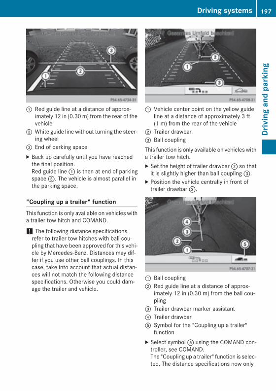
: Red guide line at a distance of approx-imately 12 in (0.30 m) from the rear of thevehicle
; White guide line without turning the steer-ing wheel
= End of parking spaceX Back up carefully until you have reached
the final position.Red guide line : is then at end of parkingspace =. The vehicle is almost parallel inthe parking space.
"Coupling up a trailer" functionThis function is only available on vehicles witha trailer tow hitch and COMAND.
! The following distance specificationsrefer to trailer tow hitches with ball cou-pling that have been approved for this vehi-cle by Mercedes-Benz. Distances may dif-fer if you use other ball couplings. In thiscase, take into account that actual distan-ces will not match the following distancespecifications. Otherwise you could dam-age the trailer and vehicle.
: Vehicle center point on the yellow guideline at a distance of approximately 3 ft(1 m) from the rear of the vehicle
; Trailer drawbar= Ball couplingThis function is only available on vehicles witha trailer tow hitch.X Set the height of trailer drawbar ; so that
it is slightly higher than ball coupling =.X Position the vehicle centrally in front of
trailer drawbar ;.
: Ball coupling; Red guide line at a distance of approx-
imately 12 in (0.30 m) from the ball cou-pling
= Trailer drawbar marker assistant? Trailer drawbarA Symbol for the "Coupling up a trailer"
functionX Select symbol A using the COMAND con-
troller, see COMAND.The "Coupling up a trailer" function is selec-ted. The distance specifications now only
Driving systems 197
Driv
ing
and
park
ing
Z
apply to objects that are at the same levelas the ball coupling.
X Back up carefully, making sure that trailerdrawbar marker assistant = pointsapproximately in the direction of trailerdrawbar ?.
X Back up carefully until the trailer draw-bar ? reaches red guide line ;.
X Couple up the trailer (Y page 212).
360° camera
General notesThe 360° camera is a system consisting offour cameras.The system analyzes images from the follow-ing cameras:RRear view cameraRFront cameraRTwo cameras in the exterior rear view mir-
rorsThe cameras capture the immediate sur-roundings of the vehicle. The system sup-ports you, e.g. when parking or if vision isrestricted at an exit.The 360° camera images can be shown in fullscreen mode or in seven different split-screenviews on the COMAND display. A split-screenview also includes a top view of the vehicle.This view is calculated from the data suppliedby the installed cameras (virtual camera).The seven split-screen views are:Rtop view and picture from the rear view
camera (130° viewing angle)Rtop view and picture from the front camera
(without displaying the maximum steeringwheel angle)Rtop view and enlarged rear viewRtop view and enlarged front viewRtop view and trailer view (vehicles with
trailer tow hitch)
Rtop view and pictures from the rearwardfacing mirror cameras (rear wheel view)Rtop view and pictures from the forward
facing mirror cameras (front wheel view)
i The top view and trailer view are availablefor vehicles equipped with a trailer towhitch.
When the function is active and you shift thetransmission from position D or R to N, yousee the previous view in the COMAND dis-play. The dynamic guidelines are hidden.When you change between transmissionpositions D and R, you see the previouslyselected front or rear view.
Important safety notesThe 360° camera is only an aid. It is not areplacement for your attention to your imme-diate surroundings. You are always responsi-ble for safe maneuvering and parking. Whenmaneuvering or parking, make sure that thereare no persons, animals or objects in the areain which you are maneuvering.The 360° camera may show a distorted viewof obstacles, show them incorrectly or not atall. It cannot show objects in the followingareas:Runder the front bumperRvery close to the front bumperRvery close to the rear bumperRunder the rear bumperRin close range above the handle on the
trunk lidRvery close to the exterior mirrorsYou are always responsible for safety, andmust always pay attention to your surround-ings when parking and maneuvering. Thisapplies to the areas behind, in front of andbeside the vehicle. You could otherwiseendanger yourself and others.The 360° camera will not function or willfunction in a limited manner:Rif the doors are openRif the exterior mirrors are folded in
198 Driving systemsDr
ivin
g an
d pa
rkin
g
Rthe tailgate is openRin heavy rain, snow or fogRat night or in very dark placesRif the cameras are exposed to very bright
lightRif the area is lit by fluorescent light or LED
lighting (the display may flicker)Rif you exit a heated garage in winter, result-
ing in a rapid change in temperatureRif the camera lenses are dirty or coveredRif the vehicle components in which the
cameras are installed are damaged. In thisevent, have the camera position and settingchecked at a qualified specialist workshop.
Do not use the 360° camera in this case. Youcan otherwise injure others or cause damageto objects or the vehicle.
Activation conditionsThe 360° camera image can be displayed if:Ryour vehicle is equipped with a 360° cam-
eraRCOMAND is switched on, see the separate
COMAND operating instructionsRthe 360° Camera function is activated
Activating the 360° camera using theSYS buttonX Press and hold the W button for longer
than 2 seconds, see the separate COMANDoperating instructions.Depending on whether position D or R isengaged, the following is shown:Rfull screen display with the image from
the front cameraRfull screen display with the image from
the rear camera
Activating the 360° camera withCOMANDX Press the W button, see the separate
COMAND operating instructions.X Select System by turning cVd the
COMAND controller and press W to con-firm.
X Select 360° Camera and press W to con-firm.Depending on whether position D or R isengaged, the following is shown:Ra split screen with top view and the
image from the front camera orRa split screen with top view and the
image from the rear view cameraFor further information about the COMANDcontroller, see the separate COMAND oper-ating instructions.
Activating the 360° camera usingreverse gearThe 360° camera images can be automati-cally displayed by engaging reverse gear.X Make sure that the SmartKey is in position
2 in the ignition lock.X Make sure that the Activation by R gear setting is active in COMAND, see theseparate COMAND operating instructions.
X To show the 360° camera image: engagereverse gear.The COMAND display shows the areabehind the vehicle in split screen:Rvehicle with guide linesRtop view of the vehicle
Selecting the split-screen and fullscreen displaysX To switch between split screen views:
switch to the line with the vehicle icons bysliding ZV the COMAND controller.
X Turn cVd the COMAND controller andselect one of the vehicle symbols.
Driving systems 199
Driv
ing
and
park
ing
Z
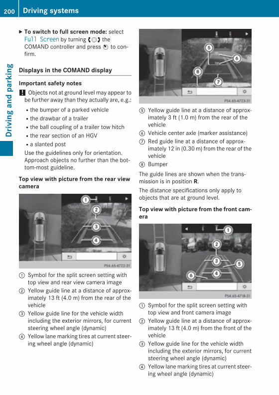
X To switch to full screen mode: selectFull Screen by turning cVd theCOMAND controller and press W to con-firm.
Displays in the COMAND display
Important safety notes! Objects not at ground level may appear to
be further away than they actually are, e.g.:Rthe bumper of a parked vehicleRthe drawbar of a trailerRthe ball coupling of a trailer tow hitchRthe rear section of an HGVRa slanted postUse the guidelines only for orientation.Approach objects no further than the bot-tom-most guideline.
Top view with picture from the rear viewcamera
: Symbol for the split screen setting withtop view and rear view camera image
; Yellow guide line at a distance of approx-imately 13 ft (4.0 m) from the rear of thevehicle
= Yellow guide line for the vehicle widthincluding the exterior mirrors, for currentsteering wheel angle (dynamic)
? Yellow lane marking tires at current steer-ing wheel angle (dynamic)
A Yellow guide line at a distance of approx-imately 3 ft (1.0 m) from the rear of thevehicle
B Vehicle center axle (marker assistance)C Red guide line at a distance of approx-
imately 12 in (0.30 m) from the rear of thevehicle
D BumperThe guide lines are shown when the trans-mission is in position R.The distance specifications only apply toobjects that are at ground level.
Top view with picture from the front cam-era
: Symbol for the split screen setting withtop view and front camera image
; Yellow guide line at a distance of approx-imately 13 ft (4.0 m) from the front of thevehicle
= Yellow guide line for the vehicle widthincluding the exterior mirrors, for currentsteering wheel angle (dynamic)
? Yellow lane marking tires at current steer-ing wheel angle (dynamic)
200 Driving systemsDr
ivin
g an
d pa
rkin
g
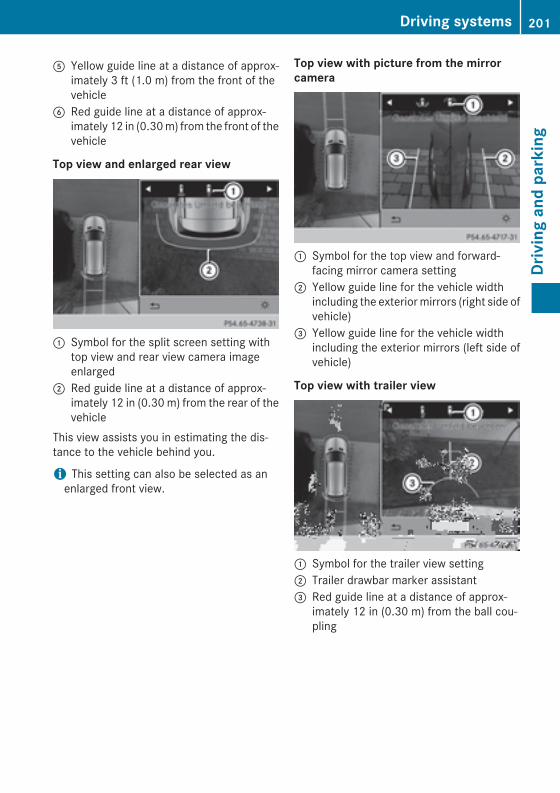
A Yellow guide line at a distance of approx-imately 3 ft (1.0 m) from the front of thevehicle
B Red guide line at a distance of approx-imately 12 in (0.30 m) from the front of thevehicle
Top view and enlarged rear view
: Symbol for the split screen setting withtop view and rear view camera imageenlarged
; Red guide line at a distance of approx-imately 12 in (0.30 m) from the rear of thevehicle
This view assists you in estimating the dis-tance to the vehicle behind you.
i This setting can also be selected as anenlarged front view.
Top view with picture from the mirrorcamera
: Symbol for the top view and forward-facing mirror camera setting
; Yellow guide line for the vehicle widthincluding the exterior mirrors (right side ofvehicle)
= Yellow guide line for the vehicle widthincluding the exterior mirrors (left side ofvehicle)
Top view with trailer view
: Symbol for the trailer view setting; Trailer drawbar marker assistant= Red guide line at a distance of approx-
imately 12 in (0.30 m) from the ball cou-pling
Driving systems 201
Driv
ing
and
park
ing
Z
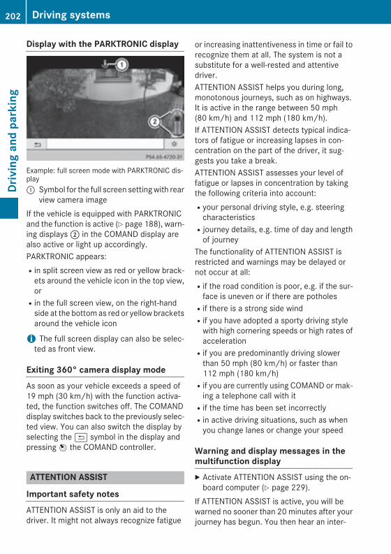
Display with the PARKTRONIC display
Example: full screen mode with PARKTRONIC dis-play: Symbol for the full screen setting with rear
view camera imageIf the vehicle is equipped with PARKTRONICand the function is active (Y page 188), warn-ing displays ; in the COMAND display arealso active or light up accordingly.PARKTRONIC appears:Rin split screen view as red or yellow brack-
ets around the vehicle icon in the top view,orRin the full screen view, on the right-hand
side at the bottom as red or yellow bracketsaround the vehicle icon
i The full screen display can also be selec-ted as front view.
Exiting 360° camera display modeAs soon as your vehicle exceeds a speed of19 mph (30 km/h) with the function activa-ted, the function switches off. The COMANDdisplay switches back to the previously selec-ted view. You can also switch the display byselecting the & symbol in the display andpressing W the COMAND controller.
ATTENTION ASSIST
Important safety notesATTENTION ASSIST is only an aid to thedriver. It might not always recognize fatigue
or increasing inattentiveness in time or fail torecognize them at all. The system is not asubstitute for a well-rested and attentivedriver.ATTENTION ASSIST helps you during long,monotonous journeys, such as on highways.It is active in the range between 50 mph(80 km/h) and 112 mph (180 km/h).If ATTENTION ASSIST detects typical indica-tors of fatigue or increasing lapses in con-centration on the part of the driver, it sug-gests you take a break.ATTENTION ASSIST assesses your level offatigue or lapses in concentration by takingthe following criteria into account:Ryour personal driving style, e.g. steering
characteristicsRjourney details, e.g. time of day and length
of journeyThe functionality of ATTENTION ASSIST isrestricted and warnings may be delayed ornot occur at all:Rif the road condition is poor, e.g. if the sur-
face is uneven or if there are potholesRif there is a strong side windRif you have adopted a sporty driving style
with high cornering speeds or high rates ofaccelerationRif you are predominantly driving slower
than 50 mph (80 km/h) or faster than112 mph (180 km/h)Rif you are currently using COMAND or mak-
ing a telephone call with itRif the time has been set incorrectlyRin active driving situations, such as when
you change lanes or change your speed
Warning and display messages in themultifunction displayX Activate ATTENTION ASSIST using the on-
board computer (Y page 229).If ATTENTION ASSIST is active, you will bewarned no sooner than 20 minutes after yourjourney has begun. You then hear an inter-
202 Driving systemsDr
ivin
g an
d pa
rkin
g
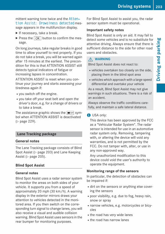
mittent warning tone twice and the Atten‐tion Assist: Drowsiness detected mes-sage appears in the multifunction display.X If necessary, take a break.X Press the a button to confirm the mes-
sage.On long journeys, take regular breaks in goodtime to allow yourself to rest properly. If youdo not take a break, you will be warned againafter 15 minutes at the earliest. The precon-dition for this is that ATTENTION ASSIST stilldetects typical indicators of fatigue orincreasing lapses in concentration.ATTENTION ASSIST is reset when you con-tinue your journey and starts assessing yourtiredness again if:Ryou switch off the engine.Ryou take off your seat belt and open the
driver's door, e.g. for a change of drivers orto take a break.
The assistance graphic shows the é sym-bol when ATTENTION ASSIST is deactivated(Y page 229).
Lane Tracking package
General notesThe Lane Tracking package consists of BlindSpot Assist (Y page 203) and Lane KeepingAssist (Y page 205).
Blind Spot Assist
General notesBlind Spot Assist uses a radar sensor systemto monitor the areas on both sides of yourvehicle. It supports you from a speed ofapproximately 20 mph (30 km/h). A warningdisplay in the exterior mirrors draws yourattention to vehicles detected in the moni-tored area. If you then switch on the corre-sponding turn signal to change lanes, you willalso receive a visual and audible collisionwarning. Blind Spot Assist uses sensors in therear bumper for monitoring purposes.
For Blind Spot Assist to assist you, the radarsensor system must be operational.
Important safety notesBlind Spot Assist is only an aid. It may fail todetect some vehicles and is no substitute forattentive driving. Always ensure that there issufficient distance to the side for other roadusers and obstacles.
G WARNINGBlind Spot Assist does not react to:Rvehicles overtaken too closely on the side,
placing them in the blind spot areaRvehicles which approach with a large speed
differential and overtake your vehicleAs a result, Blind Spot Assist may not givewarnings in such situations. There is a risk ofan accident.Always observe the traffic conditions care-fully, and maintain a safe lateral distance.
i USA only:This device has been approved by the FCCas a "Vehicular Radar System". The radarsensor is intended for use in an automotiveradar system only. Removing, tamperingwith, or altering the device will void anywarranties, and is not permitted by theFCC. Do not tamper with, alter, or use inany non-approved way.Any unauthorized modification to thisdevice could void the user’s authority tooperate the equipment.
Monitoring range of the sensorsIn particular, the detection of obstacles canbe impaired if:Rdirt on the sensors or anything else cover-
ing the sensorsRpoor visibility, e.g. due to fog, heavy rain,
snow or sprayRnarrow vehicles, e.g. motorcycles or bicy-
clesRthe road has very wide lanesRthe road has narrow lanes
Driving systems 203
Driv
ing
and
park
ing
Z
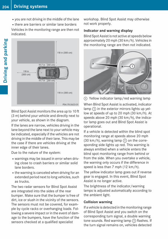
Ryou are not driving in the middle of the laneRthere are barriers or similar lane bordersVehicles in the monitoring range are then notindicated.
Blind Spot Assist monitors the area up to 10 ft(3 m) behind your vehicle and directly next toyour vehicle, as shown in the diagram.If the lanes are narrow, vehicles driving in thelane beyond the lane next to your vehicle maybe indicated, especially if the vehicles are notdriving in the middle of their lane. This may bethe case if there are vehicles driving at theinner edge of their lanes.Due to the nature of the system:Rwarnings may be issued in error when driv-
ing close to crash barriers or similar solidlane borders.Rthe warning is canceled when driving for an
extended period next to long vehicles, suchas trucks.
The two radar sensors for Blind Spot Assistare integrated into the sides of the rearbumper. Make sure that the bumper is free ofdirt, ice or slush in the vicinity of the sensors.The sensors must not be covered, for exam-ple by cycle racks or overhanging loads. Fol-lowing a severe impact or in the event of dam-age to the bumpers, have the function of thesensors checked at a qualified specialist
workshop. Blind Spot Assist may otherwisenot work properly.
Indicator and warning displayBlind Spot Assist is not active at speeds belowapproximately 20 mph (30 km/h). Vehicles inthe monitoring range are then not indicated.
: Yellow indicator lamp/red warning lampWhen Blind Spot Assist is activated, indicatorlamp : in the exterior mirrors lights up yel-low at speeds of up to 20 mph (30 km/h). Atspeeds above 20 mph (30 km/h), the indica-tor lamp goes out and Blind Spot Assist isoperational.If a vehicle is detected within the blind spotmonitoring range at speeds above 20 mph(30 km/h), warning lamp : on the corre-sponding side lights up red. This warning isalways emitted when a vehicle enters theblind spot monitoring range from behind orfrom the side. When you overtake a vehicle,the warning only occurs if the difference inspeed is less than 7 mph (12 km/h).The yellow indicator lamp goes out if reversegear is engaged. In this event, Blind SpotAssist is no longer active.The brightness of the indicator/warninglamps is adjusted automatically according tothe ambient light.
Collision warningIf a vehicle is detected in the monitoring rangeof Blind Spot Assist and you switch on thecorresponding turn signal, a double warningtone sounds. Red warning lamp : flashes. Ifthe turn signal remains on, vehicles detected
204 Driving systemsDr
ivin
g an
d pa
rkin
g
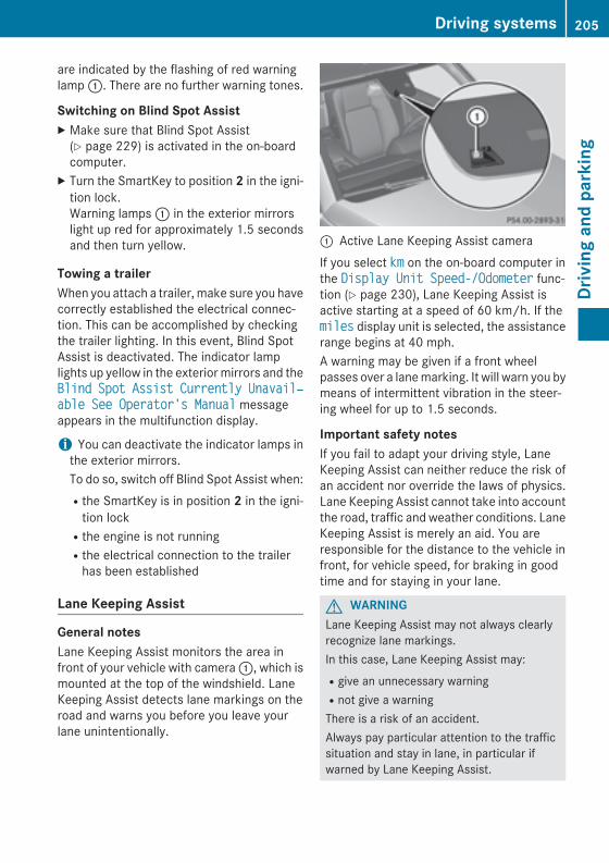
are indicated by the flashing of red warninglamp :. There are no further warning tones.
Switching on Blind Spot AssistX Make sure that Blind Spot Assist
(Y page 229) is activated in the on-boardcomputer.
X Turn the SmartKey to position 2 in the igni-tion lock.Warning lamps : in the exterior mirrorslight up red for approximately 1.5 secondsand then turn yellow.
Towing a trailerWhen you attach a trailer, make sure you havecorrectly established the electrical connec-tion. This can be accomplished by checkingthe trailer lighting. In this event, Blind SpotAssist is deactivated. The indicator lamplights up yellow in the exterior mirrors and theBlind Spot Assist Currently Unavail‐able See Operator's Manual messageappears in the multifunction display.
i You can deactivate the indicator lamps inthe exterior mirrors.To do so, switch off Blind Spot Assist when:Rthe SmartKey is in position 2 in the igni-
tion lockRthe engine is not runningRthe electrical connection to the trailer
has been established
Lane Keeping Assist
General notesLane Keeping Assist monitors the area infront of your vehicle with camera :, which ismounted at the top of the windshield. LaneKeeping Assist detects lane markings on theroad and warns you before you leave yourlane unintentionally.
: Active Lane Keeping Assist cameraIf you select km on the on-board computer inthe Display Unit Speed-/Odometer func-tion (Y page 230), Lane Keeping Assist isactive starting at a speed of 60 km/h. If themiles display unit is selected, the assistancerange begins at 40 mph.A warning may be given if a front wheelpasses over a lane marking. It will warn you bymeans of intermittent vibration in the steer-ing wheel for up to 1.5 seconds.
Important safety notesIf you fail to adapt your driving style, LaneKeeping Assist can neither reduce the risk ofan accident nor override the laws of physics.Lane Keeping Assist cannot take into accountthe road, traffic and weather conditions. LaneKeeping Assist is merely an aid. You areresponsible for the distance to the vehicle infront, for vehicle speed, for braking in goodtime and for staying in your lane.
G WARNINGLane Keeping Assist may not always clearlyrecognize lane markings.In this case, Lane Keeping Assist may:Rgive an unnecessary warningRnot give a warningThere is a risk of an accident.Always pay particular attention to the trafficsituation and stay in lane, in particular ifwarned by Lane Keeping Assist.
Driving systems 205
Driv
ing
and
park
ing
Z
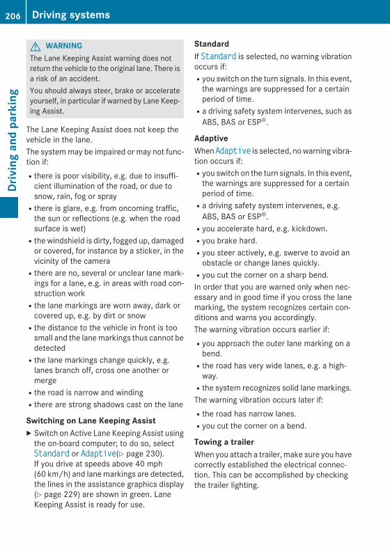
G WARNINGThe Lane Keeping Assist warning does notreturn the vehicle to the original lane. There isa risk of an accident.You should always steer, brake or accelerateyourself, in particular if warned by Lane Keep-ing Assist.
The Lane Keeping Assist does not keep thevehicle in the lane.The system may be impaired or may not func-tion if:Rthere is poor visibility, e.g. due to insuffi-
cient illumination of the road, or due tosnow, rain, fog or sprayRthere is glare, e.g. from oncoming traffic,
the sun or reflections (e.g. when the roadsurface is wet)Rthe windshield is dirty, fogged up, damaged
or covered, for instance by a sticker, in thevicinity of the cameraRthere are no, several or unclear lane mark-
ings for a lane, e.g. in areas with road con-struction workRthe lane markings are worn away, dark or
covered up, e.g. by dirt or snowRthe distance to the vehicle in front is too
small and the lane markings thus cannot bedetectedRthe lane markings change quickly, e.g.
lanes branch off, cross one another ormergeRthe road is narrow and windingRthere are strong shadows cast on the lane
Switching on Lane Keeping AssistX Switch on Active Lane Keeping Assist using
the on-board computer; to do so, selectStandard or Adaptive(Y page 230).If you drive at speeds above 40 mph(60 km/h) and lane markings are detected,the lines in the assistance graphics display(Y page 229) are shown in green. LaneKeeping Assist is ready for use.
StandardIf Standard is selected, no warning vibrationoccurs if:Ryou switch on the turn signals. In this event,
the warnings are suppressed for a certainperiod of time.Ra driving safety system intervenes, such as
ABS, BAS or ESP®.
AdaptiveWhen Adaptive is selected, no warning vibra-tion occurs if:Ryou switch on the turn signals. In this event,
the warnings are suppressed for a certainperiod of time.Ra driving safety system intervenes, e.g.
ABS, BAS or ESP®.Ryou accelerate hard, e.g. kickdown.Ryou brake hard.Ryou steer actively, e.g. swerve to avoid an
obstacle or change lanes quickly.Ryou cut the corner on a sharp bend.In order that you are warned only when nec-essary and in good time if you cross the lanemarking, the system recognizes certain con-ditions and warns you accordingly.The warning vibration occurs earlier if:Ryou approach the outer lane marking on a
bend.Rthe road has very wide lanes, e.g. a high-
way.Rthe system recognizes solid lane markings.The warning vibration occurs later if:Rthe road has narrow lanes.Ryou cut the corner on a bend.
Towing a trailerWhen you attach a trailer, make sure you havecorrectly established the electrical connec-tion. This can be accomplished by checkingthe trailer lighting.
206 Driving systemsDr
ivin
g an
d pa
rkin
g
Active Driving Assistance package
General notesThe Active Driving Assistance package con-sists of DISTRONIC PLUS (Y page 176), ActiveBlind Spot Assist (Y page 207) and ActiveLane Keeping Assist (Y page 210).
Active Blind Spot Assist
General notesActive Blind Spot Assist uses a radar sensorsystem to monitor the side areas of your vehi-cle which are behind the driver. A warningdisplay in the exterior mirrors draws yourattention to vehicles detected in the moni-tored area. If you then switch on the corre-sponding turn signal to change lane, you willalso receive an optical and audible warning. Ifa risk of lateral collision is detected, correc-tive braking may help you avoid a collision. Tosupport the course-correcting brake applica-tion, Active Blind Spot Assist uses theforward-facing radar sensor system. The freespace is then evaluated in the direction oftravel and to the side before a course-cor-recting brake application is initiated.Active Blind Spot Assist supports you from aspeed of approximately 20 mph (30 km/h).For Active Blind Spot Assist to assist youwhen driving, the radar sensor system mustbe operational.
Important safety notesActive Blind Spot Assist is only an aid. It doesnot detect all traffic situations and road usersand is no substitute for attentive driving.Always ensure that there is sufficient dis-tance to the side for other road users andobstacles.
G WARNINGActive Blind Spot Assist does not react to:Rvehicles overtaken too closely on the side,
placing them in the blind spot areaRvehicles which approach with a large speed
differential and overtake your vehicle
As a result, Active Blind Spot Assist may nei-ther give warnings nor intervene in such sit-uations. There is a risk of an accident.Always observe the traffic conditions care-fully, and maintain a safe lateral distance.
i USA only:This device has been approved by the FCCas a "Vehicular Radar System". The radarsensor is intended for use in an automotiveradar system only. Removing, tamperingwith, or altering the device will void anywarranties, and is not permitted by theFCC. Do not tamper with, alter, or use inany non-approved way.Any unauthorized modification to thisdevice could void the user’s authority tooperate the equipment.
i Canada only: This device complies withRSS-210 of Industry Canada. Operation issubject to the following two conditions:1. This device may not cause harmful inter-ference, and2. this device must accept any interferencereceived, including interference that maycause undesired operation of the device.Removal, tampering, or altering of thedevice will void any warranties, and is notpermitted. Do not tamper with, alter, or usein any non-approved way.Any unauthorized modification to thisdevice could void the user's authority tooperate the equipment.
Monitoring range of the sensorsG WARNINGActive Blind Spot Assist does not detect alltraffic situations and road users. There is arisk of an accident.Always make sure that there is sufficient dis-tance on the side for other traffic or obstacles.
Driving systems 207
Driv
ing
and
park
ing
Z
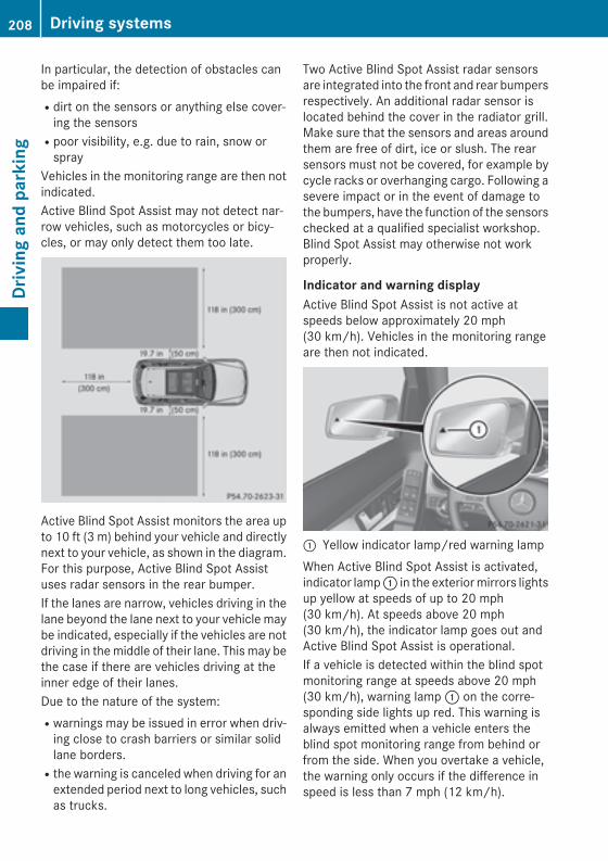
In particular, the detection of obstacles canbe impaired if:Rdirt on the sensors or anything else cover-
ing the sensorsRpoor visibility, e.g. due to rain, snow or
sprayVehicles in the monitoring range are then notindicated.Active Blind Spot Assist may not detect nar-row vehicles, such as motorcycles or bicy-cles, or may only detect them too late.
Active Blind Spot Assist monitors the area upto 10 ft (3 m) behind your vehicle and directlynext to your vehicle, as shown in the diagram.For this purpose, Active Blind Spot Assistuses radar sensors in the rear bumper.If the lanes are narrow, vehicles driving in thelane beyond the lane next to your vehicle maybe indicated, especially if the vehicles are notdriving in the middle of their lane. This may bethe case if there are vehicles driving at theinner edge of their lanes.Due to the nature of the system:Rwarnings may be issued in error when driv-
ing close to crash barriers or similar solidlane borders.Rthe warning is canceled when driving for an
extended period next to long vehicles, suchas trucks.
Two Active Blind Spot Assist radar sensorsare integrated into the front and rear bumpersrespectively. An additional radar sensor islocated behind the cover in the radiator grill.Make sure that the sensors and areas aroundthem are free of dirt, ice or slush. The rearsensors must not be covered, for example bycycle racks or overhanging cargo. Following asevere impact or in the event of damage tothe bumpers, have the function of the sensorschecked at a qualified specialist workshop.Blind Spot Assist may otherwise not workproperly.
Indicator and warning displayActive Blind Spot Assist is not active atspeeds below approximately 20 mph(30 km/h). Vehicles in the monitoring rangeare then not indicated.
: Yellow indicator lamp/red warning lampWhen Active Blind Spot Assist is activated,indicator lamp : in the exterior mirrors lightsup yellow at speeds of up to 20 mph(30 km/h). At speeds above 20 mph(30 km/h), the indicator lamp goes out andActive Blind Spot Assist is operational.If a vehicle is detected within the blind spotmonitoring range at speeds above 20 mph(30 km/h), warning lamp : on the corre-sponding side lights up red. This warning isalways emitted when a vehicle enters theblind spot monitoring range from behind orfrom the side. When you overtake a vehicle,the warning only occurs if the difference inspeed is less than 7 mph (12 km/h).
208 Driving systemsDr
ivin
g an
d pa
rkin
g
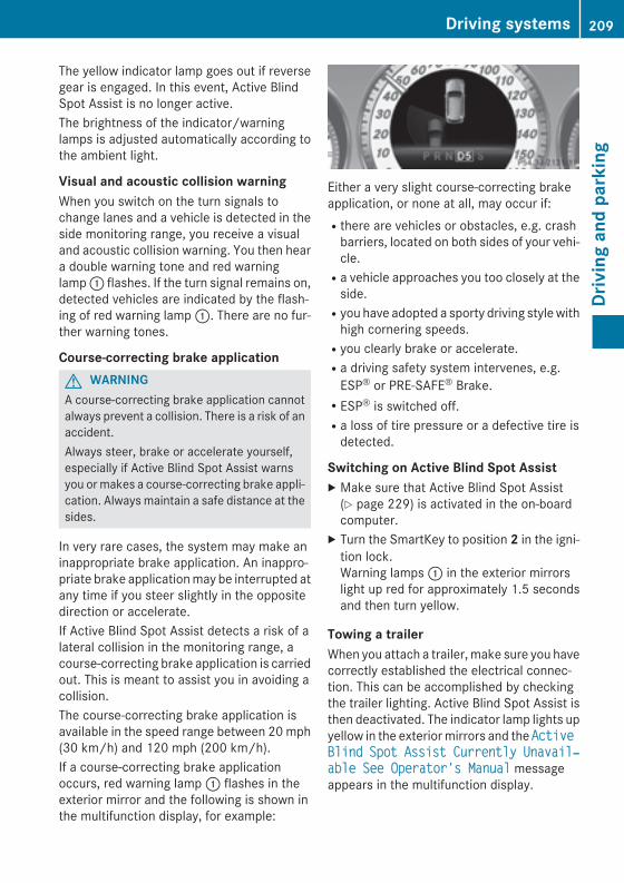
The yellow indicator lamp goes out if reversegear is engaged. In this event, Active BlindSpot Assist is no longer active.The brightness of the indicator/warninglamps is adjusted automatically according tothe ambient light.
Visual and acoustic collision warningWhen you switch on the turn signals tochange lanes and a vehicle is detected in theside monitoring range, you receive a visualand acoustic collision warning. You then heara double warning tone and red warninglamp : flashes. If the turn signal remains on,detected vehicles are indicated by the flash-ing of red warning lamp :. There are no fur-ther warning tones.
Course-correcting brake applicationG WARNINGA course-correcting brake application cannotalways prevent a collision. There is a risk of anaccident.Always steer, brake or accelerate yourself,especially if Active Blind Spot Assist warnsyou or makes a course-correcting brake appli-cation. Always maintain a safe distance at thesides.
In very rare cases, the system may make aninappropriate brake application. An inappro-priate brake application may be interrupted atany time if you steer slightly in the oppositedirection or accelerate.If Active Blind Spot Assist detects a risk of alateral collision in the monitoring range, acourse-correcting brake application is carriedout. This is meant to assist you in avoiding acollision.The course-correcting brake application isavailable in the speed range between 20 mph(30 km/h) and 120 mph (200 km/h).If a course-correcting brake applicationoccurs, red warning lamp : flashes in theexterior mirror and the following is shown inthe multifunction display, for example:
Either a very slight course-correcting brakeapplication, or none at all, may occur if:Rthere are vehicles or obstacles, e.g. crash
barriers, located on both sides of your vehi-cle.Ra vehicle approaches you too closely at the
side.Ryou have adopted a sporty driving style with
high cornering speeds.Ryou clearly brake or accelerate.Ra driving safety system intervenes, e.g.
ESP® or PRE-SAFE® Brake.RESP® is switched off.Ra loss of tire pressure or a defective tire is
detected.
Switching on Active Blind Spot AssistX Make sure that Active Blind Spot Assist
(Y page 229) is activated in the on-boardcomputer.
X Turn the SmartKey to position 2 in the igni-tion lock.Warning lamps : in the exterior mirrorslight up red for approximately 1.5 secondsand then turn yellow.
Towing a trailerWhen you attach a trailer, make sure you havecorrectly established the electrical connec-tion. This can be accomplished by checkingthe trailer lighting. Active Blind Spot Assist isthen deactivated. The indicator lamp lights upyellow in the exterior mirrors and the Active Blind Spot Assist Currently Unavail‐able See Operator's Manual messageappears in the multifunction display.
Driving systems 209
Driv
ing
and
park
ing
Z
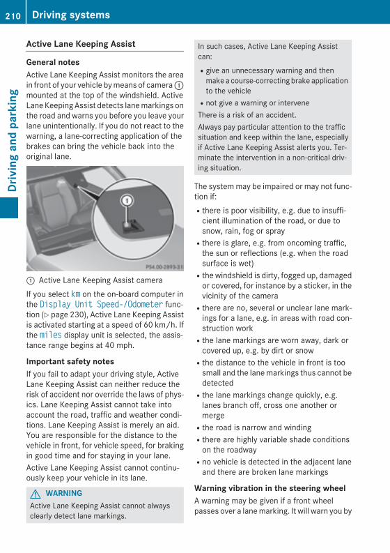
Active Lane Keeping Assist
General notesActive Lane Keeping Assist monitors the areain front of your vehicle by means of camera :mounted at the top of the windshield. ActiveLane Keeping Assist detects lane markings onthe road and warns you before you leave yourlane unintentionally. If you do not react to thewarning, a lane-correcting application of thebrakes can bring the vehicle back into theoriginal lane.
: Active Lane Keeping Assist cameraIf you select km on the on-board computer inthe Display Unit Speed-/Odometer func-tion (Y page 230), Active Lane Keeping Assistis activated starting at a speed of 60 km/h. Ifthe miles display unit is selected, the assis-tance range begins at 40 mph.
Important safety notesIf you fail to adapt your driving style, ActiveLane Keeping Assist can neither reduce therisk of accident nor override the laws of phys-ics. Lane Keeping Assist cannot take intoaccount the road, traffic and weather condi-tions. Lane Keeping Assist is merely an aid.You are responsible for the distance to thevehicle in front, for vehicle speed, for brakingin good time and for staying in your lane.Active Lane Keeping Assist cannot continu-ously keep your vehicle in its lane.
G WARNINGActive Lane Keeping Assist cannot alwaysclearly detect lane markings.
In such cases, Active Lane Keeping Assistcan:Rgive an unnecessary warning and then
make a course-correcting brake applicationto the vehicleRnot give a warning or interveneThere is a risk of an accident.Always pay particular attention to the trafficsituation and keep within the lane, especiallyif Active Lane Keeping Assist alerts you. Ter-minate the intervention in a non-critical driv-ing situation.
The system may be impaired or may not func-tion if:Rthere is poor visibility, e.g. due to insuffi-
cient illumination of the road, or due tosnow, rain, fog or sprayRthere is glare, e.g. from oncoming traffic,
the sun or reflections (e.g. when the roadsurface is wet)Rthe windshield is dirty, fogged up, damaged
or covered, for instance by a sticker, in thevicinity of the cameraRthere are no, several or unclear lane mark-
ings for a lane, e.g. in areas with road con-struction workRthe lane markings are worn away, dark or
covered up, e.g. by dirt or snowRthe distance to the vehicle in front is too
small and the lane markings thus cannot bedetectedRthe lane markings change quickly, e.g.
lanes branch off, cross one another ormergeRthe road is narrow and windingRthere are highly variable shade conditions
on the roadwayRno vehicle is detected in the adjacent lane
and there are broken lane markings
Warning vibration in the steering wheelA warning may be given if a front wheelpasses over a lane marking. It will warn you by
210 Driving systemsDr
ivin
g an
d pa
rkin
g
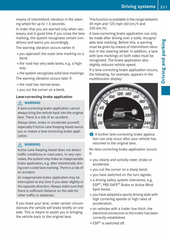
means of intermittent vibration in the steer-ing wheel for up to 1.5 seconds.In order that you are warned only when nec-essary and in good time if you cross the lanemarking, the system recognizes certain con-ditions and warns you accordingly.The warning vibration occurs earlier if:Ryou approach the outer lane marking on a
bend.Rthe road has very wide lanes, e.g. a high-
way.Rthe system recognizes solid lane markings.The warning vibration occurs later if:Rthe road has narrow lanes.Ryou cut the corner on a bend.
Lane-correcting brake applicationG WARNINGA lane-correcting brake application cannotalways bring the vehicle back into the originallane. There is a risk of an accident.Always steer, brake or accelerate yourself,especially if Active Lane Keeping Assist warnsyou or makes a lane-correcting brake appli-cation.
G WARNINGActive Lane Keeping Assist does not detecttraffic conditions or road users. In very rarecases, the system may make an inappropriatebrake application, e.g. after intentionally driv-ing over a solid lane marking. There is a risk ofan accident.An inappropriate brake application may beinterrupted at any time if you steer slightly inthe opposite direction. Always make sure thatthere is sufficient distance on the side forother traffic or obstacles.
If you leave your lane, under certain circum-stances the vehicle will brake briefly on oneside. This is meant to assist you in bringingthe vehicle back to the original lane.
This function is available in the range between40 mph and 120 mph (60 km/h and200 km/h).A lane-correcting brake application can onlybe made after driving over a solid, recogniz-able lane marking. Before this, a warningmust be given by means of intermittent vibra-tion in the steering wheel. In addition, a lanewith lane markings on both sides must berecognized. The brake application alsoslightly reduces vehicle speed.If a lane-correcting brake application occurs,the following, for example, appears in themultifunction display:
i A further lane-correcting brake applica-tion can only occur after your vehicle hasreturned to the original lane.
No lane-correcting brake application occursif:Ryou clearly and actively steer, brake or
accelerate.Ryou cut the corner on a sharp bend.Ryou have switched on the turn signals.Ra driving safety system intervenes, e.g.
ESP®, PRE-SAFE® Brake or Active BlindSpot Assist.Ryou have adopted a sporty driving style with
high cornering speeds or high rates ofacceleration.Ron vehicles with a trailer tow hitch, the
electrical connection to the trailer has beencorrectly established.RESP® is switched off.
Driving systems 211
Driv
ing
and
park
ing
Z
Rthe transmission is not in position D.Ra loss of tire pressure or a defective tire has
been detected and displayed.Active Lane Keeping Assist does not detecttraffic situations or road users. An inappro-priate brake application may be interrupted atany time if you:Rsteer slightly in the opposite directionRyou have switched on the turn signalsRclearly brake or accelerateA lane-correcting brake application is inter-rupted automatically if:Ra driving safety system intervenes, e.g.
ESP®, PRE-SAFE® Brake or Active BlindSpot Assist.Rlane markings can no longer be recognized.
Switching on Active Lane Keeping AssistX Switch on Active Lane Keeping Assist using
the on-board computer; to do so, selectStandard or Adaptive (Y page 230).If you drive at speeds above 40 mph(60 km/h) and lane markings are detected,the lines in the assistance graphics display(Y page 229) are shown in green. LaneKeeping Assist is ready for use.If Standard is selected, no warning vibra-tion occurs if:Ryou have switched on the turn signals. In
this event, the warnings are suppressedfor a certain period of time.Ra driving safety system intervenes, such
as ABS, BAS or ESP®.When Adaptive is selected, no warningvibration occurs if:Ryou have switched on the turn signals. In
this event, the warnings are suppressedfor a certain period of time.Ra driving safety system intervenes, e.g.
ABS, BAS or ESP®.Ryou accelerate hard, e.g. kickdown.Ryou brake hard.
Ryou steer actively, e.g. swerve to avoid anobstacle or change lanes quickly.Ryou cut the corner on a sharp bend.
Towing a trailerWhen you attach a trailer, make sure you havecorrectly established the electrical connec-tion. This can be accomplished by checkingthe trailer lighting.
Towing a trailer
Notes on towing a trailer
Important safety notes
G WARNINGWhen the vehicle/trailer combination beginsto lurch, you could lose control of it. The vehi-cle/trailer combination could even rollover.There is a risk of an accident.On no account should you attempt tostraighten up the vehicle/trailer combinationby increasing the speed. Reduce vehiclespeed and do not countersteer. Apply thebrake as necessary.
Please observe the manufacturer's operatinginstructions for the trailer coupling if adetachable trailer coupling is used.Couple and uncouple the trailer carefully. Ifyou do not couple the trailer to the towingvehicle correctly, the trailer could becomedetached.Make sure that the following values are notexceeded:Rthe permissible trailer drawbar noseweightRthe permissible trailer loadRthe permissible rear axle load of the towing
vehicleRthe maximum permissible gross vehicle
weight of both the towing vehicle and thetrailer
212 Towing a trailerDr
ivin
g an
d pa
rkin
g
The applicable permissible values, whichmust not be exceeded, can be found:Rin the vehicle documentsRon the identification plates of the trailer tow
hitch, the trailer and the vehicleIf the values differ, the lowest value applies.You will find the values approved by the man-ufacturer on the vehicle identification platesand those for the towing vehicle under "Tech-nical data" (Y page 381).When towing a trailer, your vehicle's handlingcharacteristics will be different in comparisonwith when driving without a trailer.The vehicle/trailer combination:Ris heavierRis restricted in its acceleration and gradi-
ent-climbing capabilityRhas an increased braking distanceRis affected more by strong crosswindsRdemands more sensitive steeringRhas a larger turning radiusThis could impair the handling characteris-tics.When towing a trailer, always adjust yourspeed to the current road and weather con-ditions. Do not exceed the maximum permis-sible speed for your vehicle/trailer combina-tion.
General notesRDo not exceed the legally prescribed max-
imum speed for vehicle/trailer combina-tions in the relevant country.This lowers the risk of an accident.ROnly install an approved trailer coupling on
your vehicle.Further information on availability and oninstallation is available from any authorizedMercedes-Benz Center.RThe bumpers of your vehicle are not suita-
ble for installing detachable trailer cou-plings.
RDo not install hired trailer couplings orother detachable trailer couplings on thebumpers of your vehicle.RTo reduce the risk of damage to the ball
coupling, remove it from the ball couplingrecess when not in use.
i When towing a trailer, set the tire pres-sure on the rear axle of the towing vehiclefor a maximum load; see the tire pressuretable in the fuel filler flap (Y page 352).
Please note that when towing a trailer,PARKTRONIC (Y page 186) is only availablewith limitations or not at all.
i On vehicles without level control, theheight of the ball coupling will alter accord-ing to the load placed on the vehicle. If nec-essary, use a trailer with a height-adjusta-ble drawbar.
You will find installation dimensions and loadsunder "Technical data" (Y page 381).
Driving tips
i Observe the notes on ESP® trailer stabi-lization (Y page 72).
The maximum permissible speed for vehicle/trailer combinations depends on the type oftrailer. Before beginning the journey, checkthe trailer's documents to see what the max-imum permissible speed is. Observe thelegally prescribed maximum speed in the rel-evant country.For certain Mercedes-Benz vehicles, the max-imum permissible rear axle load is increasedwhen towing a trailer. Refer to the "Technicaldata" section to find out whether this appliesto your vehicle.If you utilize any of the added maximum rearaxle load when towing a trailer, the vehicle/trailer combination may not exceed a maxi-mum speed of 60 mph (100 km/h) for rea-sons concerning the operating permit. Thisalso applies in countries in which the permis-sible maximum speed for vehicle/trailer com-binations is above 60 mph (100 km/h).
Towing a trailer 213
Driv
ing
and
park
ing
Z
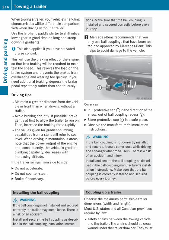
When towing a trailer, your vehicle's handlingcharacteristics will be different in comparisonwith when driving without a trailer.Use the left-hand paddle shifter to shift into alower gear in good time on long and steepdownhill gradients.
i This also applies if you have activatedcruise control.
This will use the braking effect of the engine,so that less braking will be required to main-tain the speed. This relieves the load on thebrake system and prevents the brakes fromoverheating and wearing too quickly. If youneed additional braking, depress the brakepedal repeatedly rather than continuously.
Driving tipsRMaintain a greater distance from the vehi-
cle in front than when driving without atrailer.RAvoid braking abruptly. If possible, brake
gently at first to allow the trailer to run on.Then, increase the braking force rapidly.RThe values given for gradient-climbing
capabilities from a standstill refer to sealevel. When driving in mountainous areas,note that the power output of the engineand, consequently, the vehicle's gradient-climbing capability, decreases withincreasing altitude.
If the trailer swings from side to side:X Do not accelerate.X Do not counter-steer.X Brake if necessary.
Installing the ball coupling
G WARNINGIf the ball coupling is not installed and securedcorrectly the trailer may come loose. There isa risk of an accident.Install and secure the ball coupling as descri-bed in the ball coupling installation instruc-
tions. Make sure that the ball coupling isinstalled and secured correctly before everyjourney.
! Mercedes-Benz recommends that youonly use ball couplings that have been tes-ted and approved by Mercedes-Benz. Thishelps to avoid damage to the vehicle.
Cover capX Pull protective cap : in the direction of the
arrow, out of ball coupling recess ;.X Store protective cap : in a safe place.X Observe the manufacturer's installation
instructions.
G WARNINGIf the ball coupling is not correctly installedand secured, it could come loose while drivingand endanger other road users. There is a riskof an accident and injury.Install and secure the ball coupling as descri-bed in the ball coupling manufacturer's instal-lation instructions. Make sure that the ballcoupling is correctly installed and securedbefore every journey.
Coupling up a trailerObserve the maximum permissible trailerdimensions (width and length).Most U.S. states and all Canadian provincesrequire by law:Rsafety chains between the towing vehicle
and the trailer. The chains should be cross-wound under the trailer drawbar. They must
214 Towing a trailerDr
ivin
g an
d pa
rkin
g
be fastened to the vehicle's trailer cou-pling, not to the bumper or the axle.Leave enough play in the chains to maketight cornering possible.Ra separate brake system for certain types
of trailer.Ra safety switch for braked trailers. Check
the specific legal requirements applicableto your state.If the trailer detaches from the towing vehi-cle, the safety switch applies the trailer'sbrakes.
! Do not connect the trailer's brake system(if featured) to the hydraulic brake systemof the towing vehicle, as the latter is equip-ped with an anti-lock brake system. Doingso will result in a loss of function of thebrake systems of both the vehicle and thetrailer.
i The vehicle's wiring harness features aconnection to the brake indicator lamp.
X Make sure that the automatic transmissionis set to position P.
X Apply the vehicle's parking brake.X Close all doors and the tailgate.X Couple up the trailer.X Establish all electrical connections.
Towing a trailerThere are numerous legal requirements con-cerning the towing of a trailer, e.g. speedrestrictions. Make sure that your car/trailercombination complies with the local regula-tions:Rin your place of residenceRin the location to which you are drivingThe police and local authorities can providereliable information.Observe the following when towing a trailer:RTo gain driving experience and to become
accustomed to the new handling charac-
teristics, you should practice the followingin a traffic-free location:- cornering- stopping- backing upRBefore driving, check:
- the trailer tow hitch- the safety switch for braked trailers- the safety chains- electrical connections- the lights- the wheelsRAdjust the exterior mirrors to provide an
unobstructed view of the rear section of thetrailer.RIf the trailer has electronically controlled
brakes, pull away carefully. Brake manuallyusing the brake controller and checkwhether the brakes function correctly.RSecure any objects on the trailer to prevent
the cargo from slipping when the vehicle isin motion.RWhen you couple up a trailer, check at reg-
ular intervals that the load is firmly secured.If the trailer is equipped with trailer lightsand brakes, check the trailer to ensure thatthese are working.RBear in mind that the handling will be less
stable when towing a trailer than when driv-ing without one. Avoid sudden steeringmovements.RThe vehicle/trailer combination is heavier,
accelerates more slowly, has a decreasedgradient climbing capability and a longerbraking distance.It is more susceptible to side winds andrequires more careful steering.RIf possible, avoid abrupt braking. Depress
the brake pedal moderately at first, so thatthe trailer can activate its own brakes. Thenincrease the pressure on the brake pedal.RIf the automatic transmission repeatedly
shifts between gears on uphill or downhill
Towing a trailer 215
Driv
ing
and
park
ing
Z
gradients, shift to a lower gear using theleft-hand steering wheel paddle shifter.A lower gear and lower speed reduce therisk of engine failure.RWhen driving downhill, shift to a lower gear
to utilize the engine's braking effect.Avoid continuous brake application as thismay overheat the vehicle brakes and, ifinstalled, the trailer brakes.RIf the coolant temperature increases dra-
matically while the air-conditioning systemis switched on, switch off the air-condition-ing system.Coolant heat can additionally be dissipatedby opening the windows and by setting theblower fan and the interior temperature tomaximum.RWhen overtaking, pay particular attention
to the extended length of your vehicle/trailer combination.Due to the length of the vehicle/trailercombination, you require additional roadspace in relation to the vehicle you areovertaking, before you can change back tothe original lane.
Decoupling a trailer
G WARNINGIf you uncouple a trailer with the overrunbrake engaged, you could trap your handbetween the vehicle and the trailer drawbar.There is a risk of injury.Do not uncouple a trailer if the overrun brakeis engaged.
! Do not disconnect a trailer with anengaged overrun brake. Otherwise, yourvehicle could be damaged by the rebound-ing of the overrun brake.
X Make sure that the automatic transmissionis set to position P.
X Apply the vehicle's parking brake.
X Close all doors and the tailgate.X Apply the trailer's parking brake.X Remove the trailer cable and decouple the
trailer.
Permissible trailer loads and drawbarloads
Weight specificationsThe gross trailer weight is calculated by add-ing the weight of the trailer to the weight ofthe load and equipment on the trailer.You will find installing dimensions and loadsunder "Technical data" (Y page 381).
Loading a trailerRWhen loading the trailer, make sure that
neither the permissible gross weight of thetrailer nor the gross vehicle weight isexceeded. The permissible gross vehicleweight is indicated on the identificationplate on the B-pillar on the driver's side ofthe vehicle.You can find the maximum permissible val-ues on the type plates of your vehicle andthe trailer. When calculating how muchweight the vehicle and trailer may carry,pay attention to the respective lowest val-ues.RThe trailer drawbar load on the ball coupling
must be added to the rear axle load to avoidexceeding the permissible gross axleweight. The permissible gross vehicleweight is indicated on the identificationplate on the B-pillar on the driver's side ofthe vehicle.
i Mercedes-Benz recommends a trailerload where the trailer drawbar noseweightaccounts for 8% to 15% of the trailer's per-missible gross weight.
216 Towing a trailerDr
ivin
g an
d pa
rkin
g
i The weight of other accessories, passen-gers and loads reduces:Rthe permissible trailer loadRthe permissible noseweight that your
vehicle can tow
Checking the vehicle and trailer weightRTo ensure compliance of the weight of the
towing vehicle and the trailer with the max-imum permissible values, have the vehicle/trailer combination (towing vehicle includ-ing driver, passenger, load and fully ladentrailer) weighed on a calibrated weigh-bridge.RCheck the gross axle weight rating of the
front and rear axles, the gross weight of thetrailer and trailer drawbar load.
Removing the ball couplingX Observe the manufacturer's installation
instructions.X Press the protective cap into the ball cou-
pling recess.X Make sure that the protective cap is firmly
in place.
Storing the ball couplingX Observe the manufacturer's installation
instructions.Observe the loading guidelines (Y page 274)and the safety notes regarding stowagespaces (Y page 275).
Trailer power supplyThe trailer socket of your vehicle is equippedat the factory with a permanent power supply.The permanent power supply is supplied viatrailer socket pin 4.
! You can connect accessories with a max-imum power consumption of 240 W to thepermanent power supply.You must not charge a trailer battery usingthe power supply.
The trailer's permanent power supply isswitched off in the event of low vehicle supplyvoltage and after six hours at the latest.A qualified specialist workshop can providemore information about installing the trailerelectrics.
Towing a trailer 217
Driv
ing
and
park
ing
Z

218

Useful information ............................ 220Important safety notes ..................... 220Displays and operation ..................... 220Menus and submenus ...................... 223Display messages ............................. 235Warning and indicator lamps in theinstrument cluster ............................ 260
219
On-b
oard
com
pute
r and
dis
play
s

Useful information
i This Operator's Manual describes allmodels and all standard and optional equip-ment of your vehicle available at the time ofpublication of the Operator's Manual.Country-specific differences are possible.Please note that your vehicle may not beequipped with all features described. Thisalso applies to safety-related systems andfunctions.
i Read the information on qualified special-ist workshops (Y page 27).
Important safety notes
G WARNINGIf you operate information systems and com-munication equipment integrated in the vehi-cle while driving, you will be distracted fromtraffic conditions. You could also lose controlof the vehicle. There is a risk of an accident.Only operate the equipment when the trafficsituation permits. If you are not sure that thisis possible, park the vehicle paying attentionto traffic conditions and operate the equip-ment when the vehicle is stationary.
You must observe the legal requirements forthe country in which you are currently drivingwhen operating the on-board computer.
G WARNINGIf the instrument cluster has failed or mal-functioned, you may not recognize functionrestrictions in systems relevant to safety. Theoperating safety of your vehicle may beimpaired. There is a risk of an accident.Drive on carefully. Have the vehicle checkedat a qualified specialist workshop immedi-ately.
The on-board computer only shows messagesor warnings from certain systems in the mul-tifunction display. You should therefore make
sure your vehicle is operating safely at alltimes.If the operating safety of your vehicle isimpaired, pull over as soon as it is safe to doso. Contact a qualified specialist workshop.For an overview, see the instrument panelillustration (Y page 33).
Displays and operation
Coolant temperature display
G WARNINGOpening the hood when the engine is over-heated or when there is a fire in the enginecompartment could expose you to hot gasesor other service products. There is a risk ofinjury.Let an overheated engine cool down beforeopening the hood. If there is a fire in theengine compartment, keep the hood closedand contact the fire department.
The coolant temperature gauge is in theinstrument cluster on the left-hand side.Under normal operating conditions and withthe specified coolant level, the coolant tem-perature may rise to 248 ‡ (120 †).
! A display message is shown if the coolanttemperature is too high.If the coolant temperature is over 248 ‡(120 †), do not continue driving. Theengine will otherwise be damaged.
TachometerThe red band in the tachometer indicates theengine's overrevving range.
! Do not drive in the overrevving range, asthis could damage the engine.
The fuel supply is interrupted to protect theengine when the red band is reached.
220 Displays and operationOn
-boa
rd c
ompu
ter a
nd d
ispl
ays

Outside temperature displayYou should pay special attention to road con-ditions when temperatures are around freez-ing point.Bear in mind that the outside temperaturedisplay indicates the temperature measuredand does not record the road temperature.The outside temperature display is in the mul-tifunction display (Y page 222).Changes in the outside temperature are dis-played after a short delay.
Speedometer with segmentsThe segments in the speedometer indicatewhich speed range is available.RCruise control activated (Y page 175):
The segments light up from the storedspeed to the maximum speed.RDISTRONIC PLUS activated (Y page 176):
One or two segments in the set speedrange light up.RDISTRONIC PLUS detects a vehicle in front
that is driving at a slower speed than thestored speed:The segments between the speed of thevehicle in front and the stored speed lightup.
Operating the on-board computer
Overview
: Multifunction display; Switches on the Voice Control System
(see the separate operating instructions)= Right control panel? Left control panelA Back buttonX To activate the on-board computer: turn
the SmartKey to position 1 in the ignitionlock.
You can control the multifunction display andthe settings in the on-board computer usingthe buttons on the multifunction steeringwheel.
Displays and operation 221
On-b
oard
com
pute
r and
dis
play
s
Z
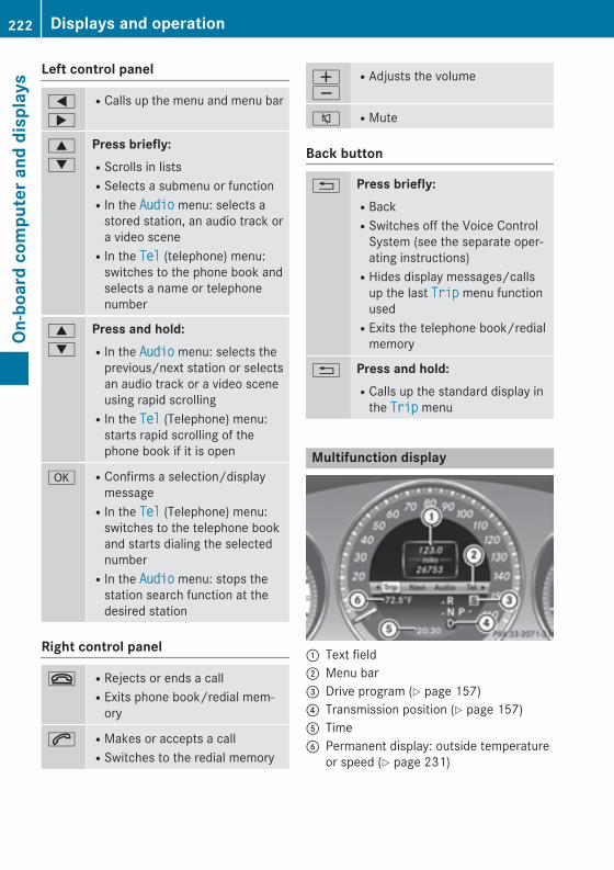
Left control panel
=
;
RCalls up the menu and menu bar
9
:
Press briefly:RScrolls in listsRSelects a submenu or functionRIn the Audio menu: selects a
stored station, an audio track ora video sceneRIn the Tel (telephone) menu:
switches to the phone book andselects a name or telephonenumber
9
:
Press and hold:RIn the Audio menu: selects the
previous/next station or selectsan audio track or a video sceneusing rapid scrollingRIn the Tel (Telephone) menu:
starts rapid scrolling of thephone book if it is open
a RConfirms a selection/displaymessageRIn the Tel (Telephone) menu:
switches to the telephone bookand starts dialing the selectednumberRIn the Audio menu: stops the
station search function at thedesired station
Right control panel
~ RRejects or ends a callRExits phone book/redial mem-
ory
6 RMakes or accepts a callRSwitches to the redial memory
WX
RAdjusts the volume
8 RMute
Back button
% Press briefly:RBackRSwitches off the Voice Control
System (see the separate oper-ating instructions)RHides display messages/calls
up the last Trip menu functionusedRExits the telephone book/redial
memory
% Press and hold:RCalls up the standard display in
the Trip menu
Multifunction display
: Text field; Menu bar= Drive program (Y page 157)? Transmission position (Y page 157)A TimeB Permanent display: outside temperature
or speed (Y page 231)
222 Displays and operationOn
-boa
rd c
ompu
ter a
nd d
ispl
ays
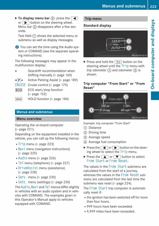
X To display menu bar ;: press the =or ; button on the steering wheel.Menu bar ; disappears after a few sec-onds.Text field : shows the selected menu orsubmenu as well as display messages.
i You can set the time using the Audio sys-tem or COMAND (see the separate operat-ing instructions).
The following messages may appear in themultifunction display:Z Gearshift recommendation when
shifting manually (Y page 160)XjY Active Parking Assist (Y page 189)CRUISE Cruise control (Y page 175)¤ ECO start/stop function
(Y page 152)ë HOLD function (Y page 184)
Menus and submenus
Menu overviewOperating the on-board computer(Y page 221).Depending on the equipment installed in thevehicle, you can call up the following menus:RTrip menu (Y page 223)RNavi menu (navigation instructions)
(Y page 225)RAudio menu (Y page 226)RTel menu (telephone) (Y page 227)RDriveAssist menu (assistance)
(Y page 228)RServ. menu (Y page 230)RSett. menu (settings) (Y page 230)The Audio, Navi and Tel menus differ slightlyin vehicles with an audio system and in vehi-cles with COMAND. The examples given inthis Operator's Manual apply to vehiclesequipped with COMAND.
Trip menu
Standard display
X Press and hold the % button on thesteering wheel until the Trip menu withtrip odometer : and odometer ; isshown.
Trip computer "From Start" or "FromReset"
Example: trip computer "From Start": Distance; Driving time= Average speed? Average fuel consumptionX Press the = or ; button on the steer-
ing wheel to select the Trip menu.X Press the 9 or : button to selectFrom Start or From Reset.
The values in the From Start submenu arecalculated from the start of a journey,whereas the values in the From Reset sub-menu are calculated from the last time thesubmenu was reset (Y page 224).The From Start trip computer is automati-cally reset if:Rthe ignition has been switched off for more
than four hours.R999 hours have been exceeded.R9,999 miles have been exceeded.
Menus and submenus 223
On-b
oard
com
pute
r and
dis
play
s
Z
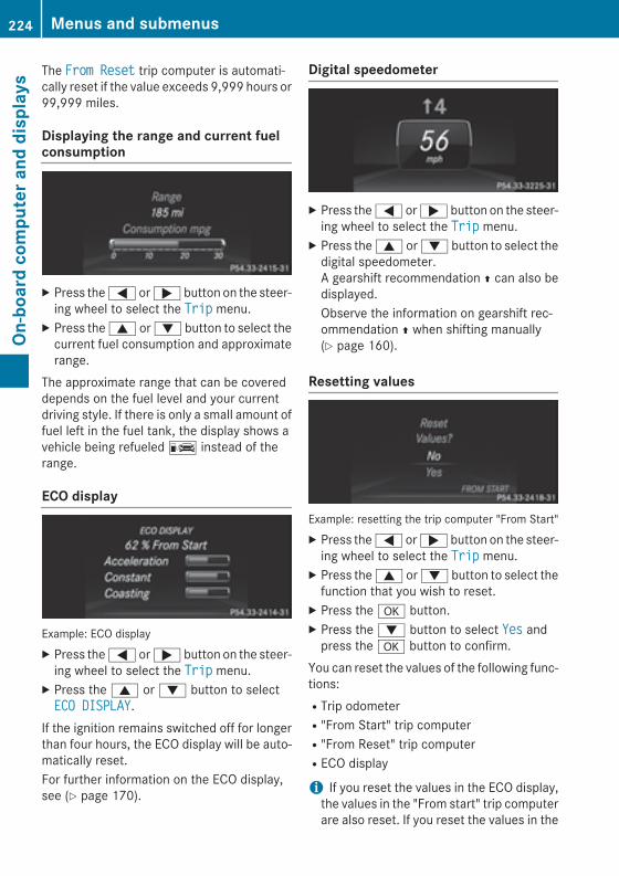
The From Reset trip computer is automati-cally reset if the value exceeds 9,999 hours or99,999 miles.
Displaying the range and current fuelconsumption
X Press the = or ; button on the steer-ing wheel to select the Trip menu.
X Press the 9 or : button to select thecurrent fuel consumption and approximaterange.
The approximate range that can be covereddepends on the fuel level and your currentdriving style. If there is only a small amount offuel left in the fuel tank, the display shows avehicle being refueled C instead of therange.
ECO display
Example: ECO displayX Press the = or ; button on the steer-
ing wheel to select the Trip menu.X Press the 9 or : button to selectECO DISPLAY.
If the ignition remains switched off for longerthan four hours, the ECO display will be auto-matically reset.For further information on the ECO display,see (Y page 170).
Digital speedometer
X Press the = or ; button on the steer-ing wheel to select the Trip menu.
X Press the 9 or : button to select thedigital speedometer.A gearshift recommendation Z can also bedisplayed.Observe the information on gearshift rec-ommendation Z when shifting manually(Y page 160).
Resetting values
Example: resetting the trip computer "From Start"X Press the = or ; button on the steer-
ing wheel to select the Trip menu.X Press the 9 or : button to select the
function that you wish to reset.X Press the a button.X Press the : button to select Yes and
press the a button to confirm.You can reset the values of the following func-tions:RTrip odometerR"From Start" trip computerR"From Reset" trip computerRECO display
i If you reset the values in the ECO display,the values in the "From start" trip computerare also reset. If you reset the values in the
224 Menus and submenusOn
-boa
rd c
ompu
ter a
nd d
ispl
ays
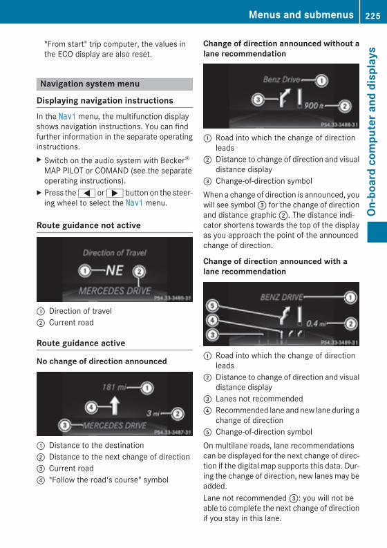
"From start" trip computer, the values inthe ECO display are also reset.
Navigation system menu
Displaying navigation instructionsIn the Navi menu, the multifunction displayshows navigation instructions. You can findfurther information in the separate operatinginstructions.X Switch on the audio system with Becker®
MAP PILOT or COMAND (see the separateoperating instructions).
X Press the = or ; button on the steer-ing wheel to select the Navi menu.
Route guidance not active
: Direction of travel; Current road
Route guidance active
No change of direction announced
: Distance to the destination; Distance to the next change of direction= Current road? "Follow the road's course" symbol
Change of direction announced without alane recommendation
: Road into which the change of directionleads
; Distance to change of direction and visualdistance display
= Change-of-direction symbolWhen a change of direction is announced, youwill see symbol = for the change of directionand distance graphic ;. The distance indi-cator shortens towards the top of the displayas you approach the point of the announcedchange of direction.
Change of direction announced with alane recommendation
: Road into which the change of directionleads
; Distance to change of direction and visualdistance display
= Lanes not recommended? Recommended lane and new lane during a
change of directionA Change-of-direction symbolOn multilane roads, lane recommendationscan be displayed for the next change of direc-tion if the digital map supports this data. Dur-ing the change of direction, new lanes may beadded.Lane not recommended =: you will not beable to complete the next change of directionif you stay in this lane.
Menus and submenus 225
On-b
oard
com
pute
r and
dis
play
s
Z
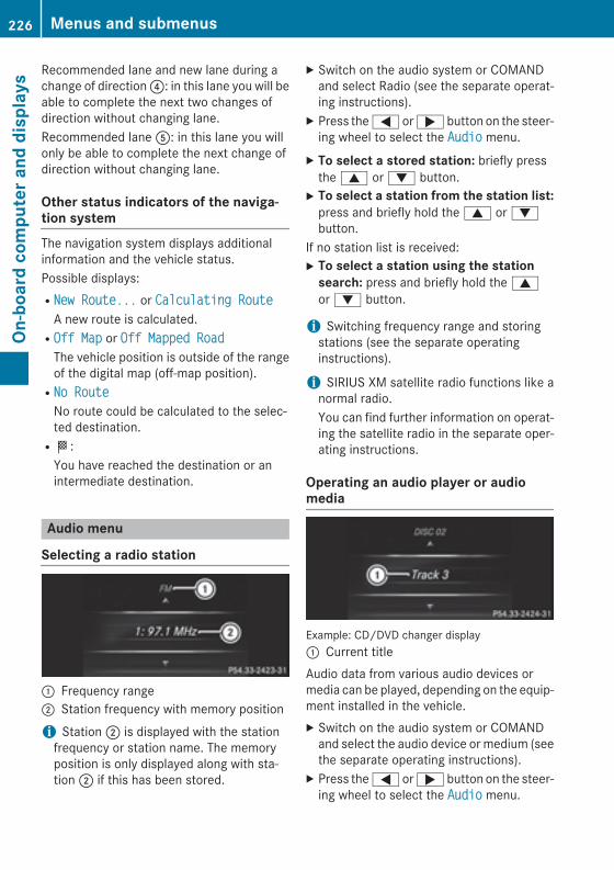
Recommended lane and new lane during achange of direction ?: in this lane you will beable to complete the next two changes ofdirection without changing lane.Recommended lane A: in this lane you willonly be able to complete the next change ofdirection without changing lane.
Other status indicators of the naviga-tion systemThe navigation system displays additionalinformation and the vehicle status.Possible displays:RNew Route... or Calculating Route
A new route is calculated.ROff Map or Off Mapped Road
The vehicle position is outside of the rangeof the digital map (off-map position).RNo Route
No route could be calculated to the selec-ted destination.RO:
You have reached the destination or anintermediate destination.
Audio menu
Selecting a radio station
: Frequency range; Station frequency with memory position
i Station ; is displayed with the stationfrequency or station name. The memoryposition is only displayed along with sta-tion ; if this has been stored.
X Switch on the audio system or COMANDand select Radio (see the separate operat-ing instructions).
X Press the = or ; button on the steer-ing wheel to select the Audio menu.
X To select a stored station: briefly pressthe 9 or : button.
X To select a station from the station list:press and briefly hold the 9 or :button.
If no station list is received:X To select a station using the station
search: press and briefly hold the 9or : button.
i Switching frequency range and storingstations (see the separate operatinginstructions).
i SIRIUS XM satellite radio functions like anormal radio.You can find further information on operat-ing the satellite radio in the separate oper-ating instructions.
Operating an audio player or audiomedia
Example: CD/DVD changer display: Current titleAudio data from various audio devices ormedia can be played, depending on the equip-ment installed in the vehicle.X Switch on the audio system or COMAND
and select the audio device or medium (seethe separate operating instructions).
X Press the = or ; button on the steer-ing wheel to select the Audio menu.
226 Menus and submenusOn
-boa
rd c
ompu
ter a
nd d
ispl
ays
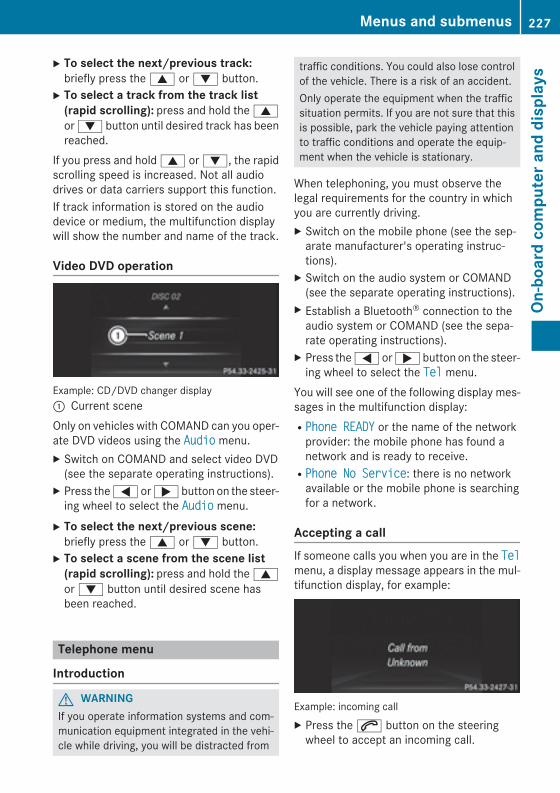
X To select the next/previous track:briefly press the 9 or : button.
X To select a track from the track list (rapid scrolling): press and hold the 9or : button until desired track has beenreached.
If you press and hold 9 or :, the rapidscrolling speed is increased. Not all audiodrives or data carriers support this function.If track information is stored on the audiodevice or medium, the multifunction displaywill show the number and name of the track.
Video DVD operation
Example: CD/DVD changer display: Current sceneOnly on vehicles with COMAND can you oper-ate DVD videos using the Audio menu.X Switch on COMAND and select video DVD
(see the separate operating instructions).X Press the = or ; button on the steer-
ing wheel to select the Audio menu.X To select the next/previous scene:
briefly press the 9 or : button.X To select a scene from the scene list
(rapid scrolling): press and hold the 9or : button until desired scene hasbeen reached.
Telephone menu
Introduction
G WARNINGIf you operate information systems and com-munication equipment integrated in the vehi-cle while driving, you will be distracted from
traffic conditions. You could also lose controlof the vehicle. There is a risk of an accident.Only operate the equipment when the trafficsituation permits. If you are not sure that thisis possible, park the vehicle paying attentionto traffic conditions and operate the equip-ment when the vehicle is stationary.
When telephoning, you must observe thelegal requirements for the country in whichyou are currently driving.X Switch on the mobile phone (see the sep-
arate manufacturer's operating instruc-tions).
X Switch on the audio system or COMAND(see the separate operating instructions).
X Establish a Bluetooth® connection to theaudio system or COMAND (see the sepa-rate operating instructions).
X Press the = or ; button on the steer-ing wheel to select the Tel menu.
You will see one of the following display mes-sages in the multifunction display:RPhone READY or the name of the network
provider: the mobile phone has found anetwork and is ready to receive.RPhone No Service: there is no network
available or the mobile phone is searchingfor a network.
Accepting a callIf someone calls you when you are in the Telmenu, a display message appears in the mul-tifunction display, for example:
Example: incoming callX Press the 6 button on the steering
wheel to accept an incoming call.
Menus and submenus 227
On-b
oard
com
pute
r and
dis
play
s
Z
You can accept a call even if you are not in theTel menu.
Rejecting or ending a callX Press the ~ button on the steering
wheel.You can end or reject a call even if you are notin the Tel menu.
Dialing an entry from the phone bookX Press the = or ; button on the steer-
ing wheel to select the Tel menu.X Press the 9, : or a button to
switch to the phone book.X Authorize access to the phone book on the
phone.X Press the 9 or : button to select the
desired name.orX To begin rapid scrolling: press and hold
the 9 or : button for longer thanone second.Rapid scrolling stops when you release thebutton or reach the end of the list.
X If only one telephone number is stored for a name: press the 6 or a buttonto start dialing.
orX If there is more than one number for a
particular name: press the 6 or abutton to display the numbers.
X Press the 9 or : button to select thenumber you want to dial.
X Press the 6 or a button to start dial-ing.
orX To exit the telephone book: press the~ or % button.
RedialingThe on-board computer saves the last namesor numbers dialed in the redial memory.
X Press the = or ; button on the steer-ing wheel to select the Tel menu.
X Press the 6 button to switch to theredial memory.
X Press the 9 or : button to select thedesired name or number.
X Press the 6 or a button to start dial-ing.
orX If you do not want to make a call: press
the ~ or % button.
Assistance menu
Introduction
Depending on the equipment installed in thevehicle, you have the following options in theDriveAssist menu:RDisplaying the assistance graphic
(Y page 229)RActivating/deactivating PRE-SAFE® Brake
(Y page 229)RActivating/deactivating ATTENTION
ASSIST (Y page 229)RActivating/deactivating Blind Spot Assist
or Active Blind Spot Assist (Y page 229)RActivating/deactivating Lane Keeping
Assist or Active Lane Keeping Assist(Y page 230)
228 Menus and submenusOn
-boa
rd c
ompu
ter a
nd d
ispl
ays
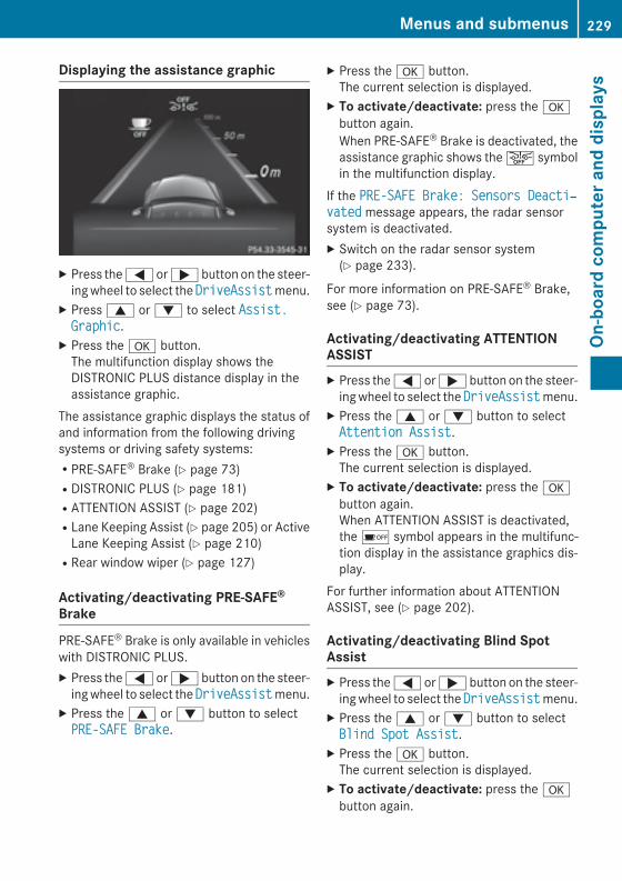
Displaying the assistance graphic
X Press the = or ; button on the steer-ing wheel to select the DriveAssist menu.
X Press 9 or : to select Assist. Graphic.
X Press the a button.The multifunction display shows theDISTRONIC PLUS distance display in theassistance graphic.
The assistance graphic displays the status ofand information from the following drivingsystems or driving safety systems:RPRE-SAFE® Brake (Y page 73)RDISTRONIC PLUS (Y page 181)RATTENTION ASSIST (Y page 202)RLane Keeping Assist (Y page 205) or Active
Lane Keeping Assist (Y page 210)RRear window wiper (Y page 127)
Activating/deactivating PRE-SAFE®
Brake
PRE‑SAFE® Brake is only available in vehicleswith DISTRONIC PLUS.X Press the = or ; button on the steer-
ing wheel to select the DriveAssist menu.X Press the 9 or : button to selectPRE-SAFE Brake.
X Press the a button.The current selection is displayed.
X To activate/deactivate: press the abutton again.When PRE-SAFE® Brake is deactivated, theassistance graphic shows the æ symbolin the multifunction display.
If the PRE-SAFE Brake: Sensors Deacti‐vated message appears, the radar sensorsystem is deactivated.X Switch on the radar sensor system
(Y page 233).
For more information on PRE‑SAFE® Brake,see (Y page 73).
Activating/deactivating ATTENTIONASSISTX Press the = or ; button on the steer-
ing wheel to select the DriveAssist menu.X Press the 9 or : button to selectAttention Assist.
X Press the a button.The current selection is displayed.
X To activate/deactivate: press the abutton again.When ATTENTION ASSIST is deactivated,the é symbol appears in the multifunc-tion display in the assistance graphics dis-play.
For further information about ATTENTIONASSIST, see (Y page 202).
Activating/deactivating Blind SpotAssistX Press the = or ; button on the steer-
ing wheel to select the DriveAssist menu.X Press the 9 or : button to selectBlind Spot Assist.
X Press the a button.The current selection is displayed.
X To activate/deactivate: press the abutton again.
Menus and submenus 229
On-b
oard
com
pute
r and
dis
play
s
Z
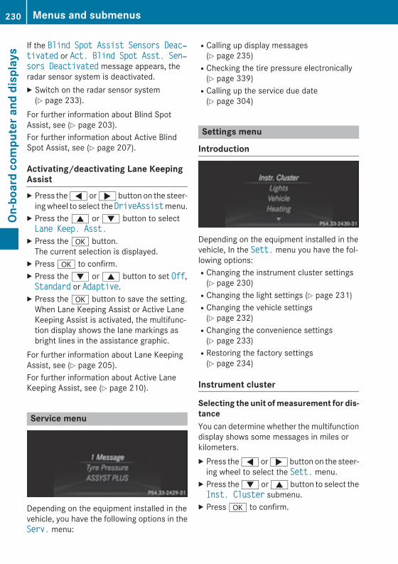
If the Blind Spot Assist Sensors Deac‐tivated or Act. Blind Spot Asst. Sen‐sors Deactivated message appears, theradar sensor system is deactivated.X Switch on the radar sensor system
(Y page 233).For further information about Blind SpotAssist, see (Y page 203).For further information about Active BlindSpot Assist, see (Y page 207).
Activating/deactivating Lane KeepingAssistX Press the = or ; button on the steer-
ing wheel to select the DriveAssist menu.X Press the 9 or : button to selectLane Keep. Asst.
X Press the a button.The current selection is displayed.
X Press a to confirm.X Press the : or 9 button to set Off,Standard or Adaptive.
X Press the a button to save the setting.When Lane Keeping Assist or Active LaneKeeping Assist is activated, the multifunc-tion display shows the lane markings asbright lines in the assistance graphic.
For further information about Lane KeepingAssist, see (Y page 205).For further information about Active LaneKeeping Assist, see (Y page 210).
Service menu
Depending on the equipment installed in thevehicle, you have the following options in theServ. menu:
RCalling up display messages(Y page 235)RChecking the tire pressure electronically
(Y page 339)RCalling up the service due date
(Y page 304)
Settings menu
Introduction
Depending on the equipment installed in thevehicle, In the Sett. menu you have the fol-lowing options:RChanging the instrument cluster settings
(Y page 230)RChanging the light settings (Y page 231)RChanging the vehicle settings
(Y page 232)RChanging the convenience settings
(Y page 233)RRestoring the factory settings
(Y page 234)
Instrument cluster
Selecting the unit of measurement for dis-tanceYou can determine whether the multifunctiondisplay shows some messages in miles orkilometers.X Press the = or ; button on the steer-
ing wheel to select the Sett. menu.X Press the : or 9 button to select theInst. Cluster submenu.
X Press a to confirm.
230 Menus and submenusOn
-boa
rd c
ompu
ter a
nd d
ispl
ays
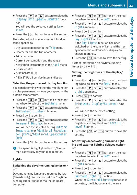
X Press the : or 9 button to select theDisplay Unit Speed-/Odometer func-tion.You will see the selected setting: km ormiles.
X Press the a button to save the setting.The selected unit of measurement for dis-tance applies to:RDigital speedometer in the Trip menuROdometer and the trip odometerRTrip computerRCurrent consumption and the rangeRNavigation instructions in the Navi menuRCruise controlRDISTRONIC PLUSRASSYST PLUS service interval display
Selecting the permanent display functionYou can determine whether the multifunctiondisplay permanently shows your speed or theoutside temperature.X Press the = or ; button on the steer-
ing wheel to select the Settings menu.X Press the : or 9 button to select theInstrument Cluster submenu.
X Press a to confirm.X Press the : or 9 button to select thePermanent Display: function.You will see the selected setting Outside Temperature or Additional Speedome‐ter [km/h]/Additional Speedometer [mph].
X Press the a button to save the setting.
i The speed is highlighted in km/h or inmph conversely to your speedometer.
Lights
Switching the daytime running lamps on/offDaytime running lamps are required by law(Canada only). You cannot set the "daytimerunning lamps" function via the on-boardcomputer.
X Press the = or ; button on the steer-ing wheel to select the Sett. menu.
X Press the : or 9 button to select theLights submenu.
X Press a to confirm.X Press the : or 9 button to select theDay Lights function.If the Day Lights function has beenswitched on, the cone of light and the Wsymbol in the multifunction display areshown in orange.
X Press the a button to save the setting.Further information on daytime runninglamps (Y page 116).
Setting the brightness of the display/switchX Press the = or ; button on the steer-
ing wheel to select the Sett. menu.X Press the : or 9 button to select theLights submenu.
X Press a to confirm.X Press the : or 9 button to select theBrightness Display/Switches: func-tion.You will see the selected setting.
X Press a to confirm.X Press the : or 9 button to adjust the
brightness to any level from Level 1 toLevel 5 (bright).
X Press the a or % button to save thesetting.
Activating/deactivating surround light-ing and exterior lighting delayed switch-offX Press the = or ; button on the steer-
ing wheel to select the Sett. menu.X Press the : or 9 button to select theLights submenu.
X Press a to confirm.X Press the : or 9 button to select theSurround Lighting function.When the Surround Lighting function isactivated, the light cone and the area
Menus and submenus 231
On-b
oard
com
pute
r and
dis
play
s
Z
around the vehicle are displayed in orangein the multifunction display.
X Press the a button to save the setting.
Deactivating delayed switch-off of the exte-rior lighting temporarily:X Before leaving the vehicle, turn the Smart-
Key to position 0 in the ignition lock.X Turn the SmartKey to position 2 in the igni-
tion lock.The exterior lighting delayed switch-off isdeactivated.
Delayed switch-off of the exterior lighting isreactivated the next time you start theengine.If you have activated the Surround Light‐ing function and the light switch is set toÃ, the following functions are activatedwhen it is dark:Rsurround lighting: the exterior lighting
remains lit for 40 seconds after unlockingwith the SmartKey. If you start the engine,the surround lighting is switched off andautomatic headlamp mode is activated(Y page 116).Rexterior lighting delayed switch-off: the
exterior lighting remains lit for 60 secondsafter the engine is switched off. If you closeall the doors and the tailgate, the exteriorlighting goes off after 5 seconds.
i Depending on your vehicle's equipment,when the surround lighting and delayedswitch-off exterior lighting are on, the fol-lowing light up:RParking lampsRFront fog lampsRLow-beam headlampsRDaytime running lampsRSide marker lampsRSurround lighting in the exterior mirrors
Activating/deactivating the interior light-ing delayed switch-offIf you activate the Interior Lighting Delay function, the interior lighting remains
on for 20 seconds after you remove theSmartKey from the ignition lock.X Press the = or ; button on the steer-
ing wheel to select the Sett menu.X Press the : or 9 button to select theLights submenu.
X Press a to confirm.X Press the : or 9 button to select theInterior Lighting Delay function.If the Interior Lighting Delay functionhas been switched on, the vehicle interior isdisplayed in orange in the multifunctiondisplay.
X Press the a button to save the setting.
Vehicle
Activating/deactivating the automaticdoor locking mechanismX Press the = or ; button on the steer-
ing wheel to select the Sett. menu.X Press the : or 9 button to select theVehicle submenu.
X Press a to confirm.X Press the : or 9 button to select theAuto. Door Locks function.When the Auto. Door Locks function isactivated, the vehicle doors are displayedin orange in the multifunction display.
X Press the a button to save the setting.If you activate the Auto. Door Locks func-tion, the vehicle is centrally locked above aspeed of around 9 mph (15 km/h).For further information on the automatic lock-ing feature, see (Y page 86).
Activating/deactivating the acousticlocking verification signalIf you switch on the Acoustic Lock function,an acoustic signal sounds when you lock thevehicle.X Press the = or ; button on the steer-
ing wheel to select the Sett. menu.X Press the : or 9 button to select theVehicle submenu.
232 Menus and submenusOn
-boa
rd c
ompu
ter a
nd d
ispl
ays
X Press a to confirm.X Press the : or 9 button to select theAcoustic Lock function.If the Acoustic Lock function is activated,the & symbol in the multifunction dis-play lights up orange.
X Press the a button to save the setting.
Activating/deactivating the radar sensorsystemX Press the = or ; button on the steer-
ing wheel to select the Sett. menu.X Press the : or 9 button to select theVehicle submenu.
X Press a to confirm.X Press the 9 or : button to selectRadar Sensor (See Oper. Manual):.You will see the selected setting: Enabledor Disabled.
X Press the a button to save the setting.The following systems are switched off whenthe radar sensor system is deactivated:RDISTRONIC PLUS (Y page 176)RBAS PLUS (Y page 69)RPRE-SAFE® Brake (Y page 73)RBlind Spot Assist (Y page 203)RActive Blind Spot Assist (Y page 207)
Convenience
Activating/deactivating the EASY-ENTRY/EXIT featureG WARNINGWhen the EASY-ENTRY/EXIT feature adjuststhe steering wheel, you and other vehicleoccupants – particularly children – couldbecome trapped. There is a risk of injury.While the EASY-ENTRY/EXIT feature is mak-ing adjustments, make sure that no one hasany body parts in the sweep of the steeringwheel.
If somebody becomes trapped:Rpress one of the memory function position
buttons, orRmove the switch for steering wheel adjust-
ment in the opposite direction to that inwhich the steering wheel is moving.
The adjustment process is stopped.
X Press the = or ; button on the steer-ing wheel to select the Sett. menu.
X Press the : or 9 button to select theConvenience submenu.
X Press a to confirm.X Press the : or 9 button to select theEasy Entry/Exit function.If the Easy Entry/Exit function is activa-ted, the vehicle steering wheel is displayedin orange in the multifunction display.
X Press the a button to save the setting.Further information on the EASY-ENTRY/EXITfeature (Y page 108).
Switching the belt adjustment on/offX Press the = or ; button on the steer-
ing wheel to select the Sett. menu.X Press the : or 9 button to select theConvenience submenu.
X Press a to confirm.X Press the : or 9 button to select theBelt Adjustment function.When the Belt Adjustment function isactivated, the vehicle seat belt is displayedin orange in the multifunction display.
X Press the a button to save the setting.For further information on belt adjustment,see (Y page 59).
Switching the fold-in mirrors when lock-ing feature on/offThis function is only available in Canada.This function is only available when the vehi-cle is equipped with the electrical fold-in func-tion.When you switch on the Auto. Mirror Folding function, the exterior mirrors are
Menus and submenus 233
On-b
oard
com
pute
r and
dis
play
s
Z
folded in when the vehicle is locked. If youunlock the vehicle and then open the driver'sor front-passenger door, the exterior mirrorsfold out again.X Press the = or ; button on the steer-
ing wheel to select the Sett. menu.X Press the : or 9 button to select theConvenience submenu.
X Press a to confirm.X Press the : or 9 button to select theAuto. Mirror Folding function.If the Auto. Mirror Folding function isswitched on, the vehicle's exterior mirror isdisplayed in orange in the multifunctiondisplay.
X Press the a button to save the setting.If you have switched the Auto. Mirror Folding function on and you fold the exteriormirrors in using the button on the door(Y page 110), they will not fold out automat-ically. The exterior mirrors can then only befolded out using the button on the door.
Restoring the factory settingsX Press the = or ; button on the steer-
ing wheel to select the Sett. menu.X Press the : or 9 button to select theFactory Setting submenu.
X Press a to confirm.The Reset All Settings? messageappears.
X Press the : or 9 button to select Noor Yes.
X Press the a button to confirm the selec-tion.If you have selected Yes, the multifunctiondisplay shows a confirmation message.
For safety reasons, the Day Lights functionin the Lights submenu is only reset if thevehicle is stationary.
234 Menus and submenusOn
-boa
rd c
ompu
ter a
nd d
ispl
ays
Display messages
General notesDisplay messages appear in the multifunction display.Display messages with graphic displays may be shown in simplified form in the Operator'sManual and may therefore differ from the multifunction display.Please respond in accordance with the display messages and follow the additional notes in thisOperator's Manual.Certain display messages are accompanied by an audible warning tone or a continuous tone.When the ignition is switched off, all display messages are deleted, apart from some high-priority display messages. Once the causes of the high-priority display messages have beenrectified, the corresponding display messages are also deleted.When you stop and park the vehicle, please observe the notes on the HOLD function(Y page 184) and parking (Y page 168).
Hiding display messagesX Press the a or % button on the steering wheel to hide the display message.
The display message is cleared.The multifunction display shows high-priority display messages in red. Some high-priority dis-play messages cannot be hidden.The multifunction display shows these messages continuously until the causes for the mes-sages have been remedied.
Message memoryThe message memory allows you to call up previous display messages.X Press the = or ; button on the steering wheel to select the Serv. menu.
If there are display messages, the multifunction display shows 2 messages, for example.X Press the 9 or : button to select the entry, e.g. 2 messages.X Press a to confirm.X Press the 9 or : button to scroll through the display messages.
Display messages 235
On-b
oard
com
pute
r and
dis
play
s
Z
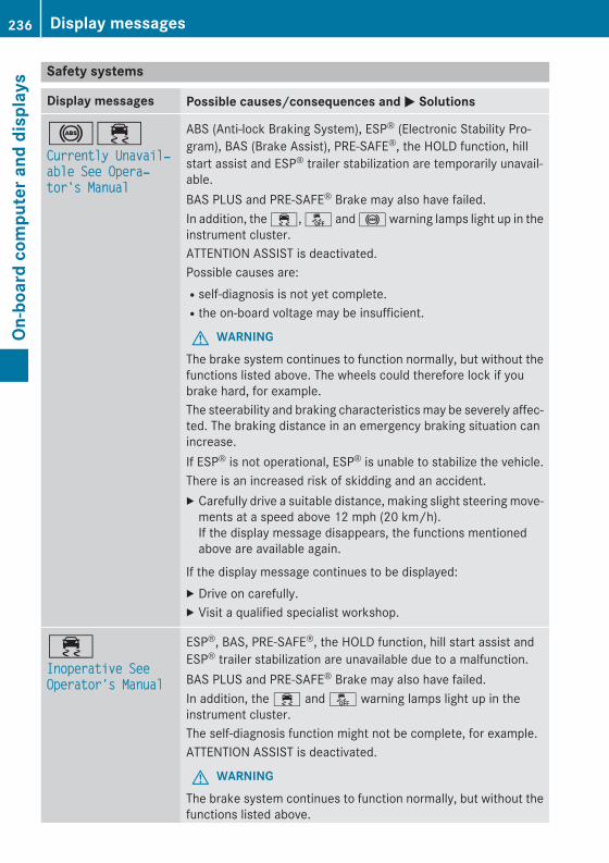
Safety systems
Display messages Possible causes/consequences and M Solutions
!÷Currently Unavail‐able See Opera‐tor's Manual
ABS (Anti-lock Braking System), ESP® (Electronic Stability Pro-gram), BAS (Brake Assist), PRE-SAFE®, the HOLD function, hillstart assist and ESP® trailer stabilization are temporarily unavail-able.BAS PLUS and PRE‑SAFE® Brake may also have failed.In addition, the ÷, å and ! warning lamps light up in theinstrument cluster.ATTENTION ASSIST is deactivated.Possible causes are:Rself-diagnosis is not yet complete.Rthe on-board voltage may be insufficient.
G WARNINGThe brake system continues to function normally, but without thefunctions listed above. The wheels could therefore lock if youbrake hard, for example.The steerability and braking characteristics may be severely affec-ted. The braking distance in an emergency braking situation canincrease.If ESP® is not operational, ESP® is unable to stabilize the vehicle.There is an increased risk of skidding and an accident.X Carefully drive a suitable distance, making slight steering move-
ments at a speed above 12 mph (20 km/h).If the display message disappears, the functions mentionedabove are available again.
If the display message continues to be displayed:X Drive on carefully.X Visit a qualified specialist workshop.
÷Inoperative See Operator's Manual
ESP®, BAS, PRE-SAFE®, the HOLD function, hill start assist andESP® trailer stabilization are unavailable due to a malfunction.BAS PLUS and PRE‑SAFE® Brake may also have failed.In addition, the ÷ and å warning lamps light up in theinstrument cluster.The self-diagnosis function might not be complete, for example.ATTENTION ASSIST is deactivated.
G WARNINGThe brake system continues to function normally, but without thefunctions listed above.
236 Display messagesOn
-boa
rd c
ompu
ter a
nd d
ispl
ays
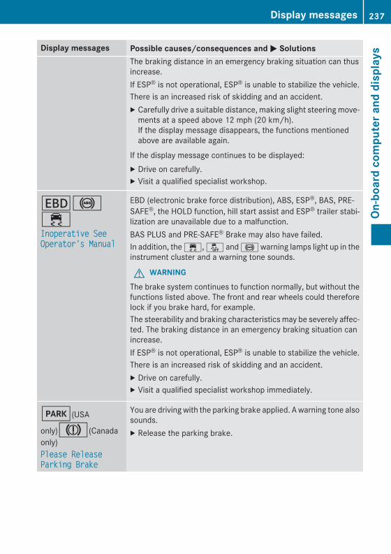
Display messages Possible causes/consequences and M SolutionsThe braking distance in an emergency braking situation can thusincrease.If ESP® is not operational, ESP® is unable to stabilize the vehicle.There is an increased risk of skidding and an accident.X Carefully drive a suitable distance, making slight steering move-
ments at a speed above 12 mph (20 km/h).If the display message disappears, the functions mentionedabove are available again.
If the display message continues to be displayed:X Drive on carefully.X Visit a qualified specialist workshop.
T!÷Inoperative See Operator's Manual
EBD (electronic brake force distribution), ABS, ESP®, BAS, PRE-SAFE®, the HOLD function, hill start assist and ESP® trailer stabi-lization are unavailable due to a malfunction.BAS PLUS and PRE‑SAFE® Brake may also have failed.In addition, the ÷, å and ! warning lamps light up in theinstrument cluster and a warning tone sounds.
G WARNINGThe brake system continues to function normally, but without thefunctions listed above. The front and rear wheels could thereforelock if you brake hard, for example.The steerability and braking characteristics may be severely affec-ted. The braking distance in an emergency braking situation canincrease.If ESP® is not operational, ESP® is unable to stabilize the vehicle.There is an increased risk of skidding and an accident.X Drive on carefully.X Visit a qualified specialist workshop immediately.
F(USA
only)J(Canadaonly)Please Release Parking Brake
You are driving with the parking brake applied. A warning tone alsosounds.X Release the parking brake.
Display messages 237
On-b
oard
com
pute
r and
dis
play
s
Z

Display messages Possible causes/consequences and M Solutions
$(USA
only)J(Canadaonly)Check Brake Fluid Level
There is not enough brake fluid in the brake fluid reservoir.In addition, the $ (USA only)/J (Canada only) warninglamp lights up in the instrument cluster and a warning tonesounds.
G WARNINGThe braking effect may be impaired.There is a risk of an accident.X Pull over and stop the vehicle safely as soon as possible, paying
attention to road and traffic conditions. Do not continue drivingunder any circumstances.
X Secure the vehicle against rolling away (Y page 168).X Consult a qualified specialist workshop.X Do not add brake fluid. This does not correct the malfunction.
#Check Brake Pad Wear
The brake pads/linings have reached their wear limit.X Visit a qualified specialist workshop.
G Inoperative
One or more main features of the mbrace system are malfunc-tioning.X Have the mbrace system checked immediately at a qualified
specialist workshop.
PRE-SAFEInoperative See Operator's Manual
Important functions of PRE-SAFE® have failed. All other occupantsafety systems, e.g. air bags, remain available.X Visit a qualified specialist workshop immediately.
238 Display messagesOn
-boa
rd c
ompu
ter a
nd d
ispl
ays
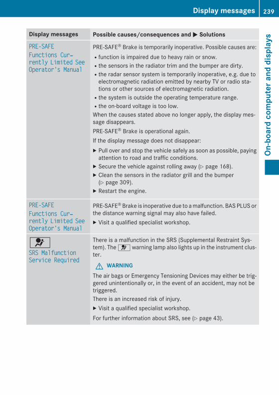
Display messages Possible causes/consequences and M Solutions
PRE-SAFEFunctions Cur‐rently Limited See Operator's Manual
PRE-SAFE® Brake is temporarily inoperative. Possible causes are:Rfunction is impaired due to heavy rain or snow.Rthe sensors in the radiator trim and the bumper are dirty.Rthe radar sensor system is temporarily inoperative, e.g. due to
electromagnetic radiation emitted by nearby TV or radio sta-tions or other sources of electromagnetic radiation.Rthe system is outside the operating temperature range.Rthe on-board voltage is too low.When the causes stated above no longer apply, the display mes-sage disappears.PRE‑SAFE® Brake is operational again.If the display message does not disappear:X Pull over and stop the vehicle safely as soon as possible, paying
attention to road and traffic conditions.X Secure the vehicle against rolling away (Y page 168).X Clean the sensors in the radiator grill and the bumper
(Y page 309).X Restart the engine.
PRE-SAFEFunctions Cur‐rently Limited See Operator's Manual
PRE-SAFE® Brake is inoperative due to a malfunction. BAS PLUS orthe distance warning signal may also have failed.X Visit a qualified specialist workshop.
6SRS Malfunction Service Required
There is a malfunction in the SRS (Supplemental Restraint Sys-tem). The 6 warning lamp also lights up in the instrument clus-ter.
G WARNINGThe air bags or Emergency Tensioning Devices may either be trig-gered unintentionally or, in the event of an accident, may not betriggered.There is an increased risk of injury.X Visit a qualified specialist workshop.For further information about SRS, see (Y page 43).
Display messages 239
On-b
oard
com
pute
r and
dis
play
s
Z
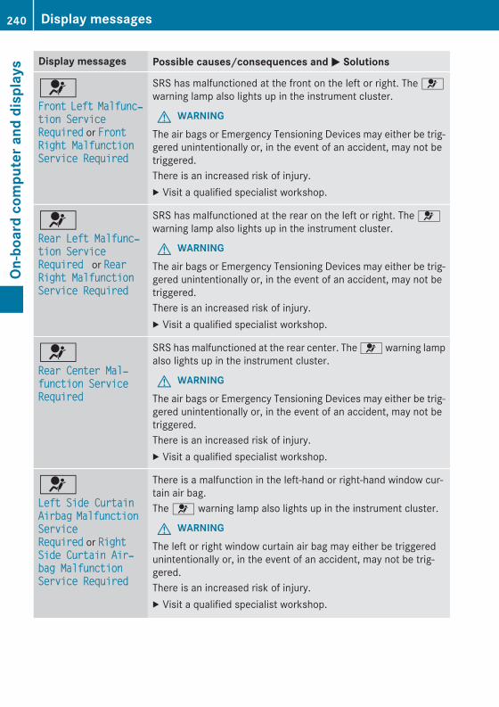
Display messages Possible causes/consequences and M Solutions
6Front Left Malfunc‐tion Service Required or Front Right Malfunction Service Required
SRS has malfunctioned at the front on the left or right. The 6warning lamp also lights up in the instrument cluster.
G WARNINGThe air bags or Emergency Tensioning Devices may either be trig-gered unintentionally or, in the event of an accident, may not betriggered.There is an increased risk of injury.X Visit a qualified specialist workshop.
6Rear Left Malfunc‐tion Service Required or Rear Right Malfunction Service Required
SRS has malfunctioned at the rear on the left or right. The 6warning lamp also lights up in the instrument cluster.
G WARNINGThe air bags or Emergency Tensioning Devices may either be trig-gered unintentionally or, in the event of an accident, may not betriggered.There is an increased risk of injury.X Visit a qualified specialist workshop.
6Rear Center Mal‐function Service Required
SRS has malfunctioned at the rear center. The 6 warning lampalso lights up in the instrument cluster.
G WARNINGThe air bags or Emergency Tensioning Devices may either be trig-gered unintentionally or, in the event of an accident, may not betriggered.There is an increased risk of injury.X Visit a qualified specialist workshop.
6Left Side Curtain Airbag Malfunction Service Required or Right Side Curtain Air‐bag Malfunction Service Required
There is a malfunction in the left-hand or right-hand window cur-tain air bag.The 6 warning lamp also lights up in the instrument cluster.
G WARNINGThe left or right window curtain air bag may either be triggeredunintentionally or, in the event of an accident, may not be trig-gered.There is an increased risk of injury.X Visit a qualified specialist workshop.
240 Display messagesOn
-boa
rd c
ompu
ter a
nd d
ispl
ays
Display messages Possible causes/consequences and M Solutions
Front Passenger Airbag DisabledSee Operator's Man‐ual
The front-passenger air bag is deactivated during the journey, eventhough:Ran adult
orRa person of the corresponding stature is on the front-passenger
seatIf additional forces are applied to the seat, the system may inter-pret the occupant's weight as lower than it actually is.
G WARNINGThe front-passenger air bag does not deploy during an accident.There is an increased risk of injury.X Pull over and stop the vehicle safely as soon as possible, paying
attention to road and traffic conditions.X Secure the vehicle against rolling away (Y page 168).X Switch the ignition off.X Have the occupant get out of the vehicle.X Keep the seat unoccupied, close the front-passenger door and
switch on the ignition.X Observe the PASSENGER AIR BAG OFF indicator lamp in the
center console and the multifunction display and check the fol-lowing:
Seat unoccupied and ignition switched on:Rthe PASSENGER AIR BAG OFF indicator lamp must then light up
and remain lit. If the indicator lamp is on, OCS has disabled thefront-passenger front air bag (Y page 49)Rthe Front Passenger Airbag Enabled See Operator's Manual or Front Passenger Airbag Disabled See Oper‐ator's Manual display messages must not be shown in themultifunction display.
X Wait for a period of at least 60 seconds until the necessary sys-tem checks have been completed.
X Make sure that the display messages do not appear in the mul-tifunction display.
If these conditions are fulfilled, the front-passenger seat can beoccupied again. Whether the PASSENGER AIR BAG OFF indicatorlamp remains lit or goes out depends on how OCS classifies theoccupant.If the conditions are not fulfilled, the system is not operating cor-rectly.X Visit a qualified specialist workshop immediately.
Display messages 241
On-b
oard
com
pute
r and
dis
play
s
Z
Display messages Possible causes/consequences and M SolutionsFor further information about the Occupant Classification System,see (Y page 49).
Front Passenger Airbag EnabledSee Operator's Man‐ual
The front-passenger air bag is enabled during the journey, eventhough:Ra child, a small adult or an object weighing less than the sys-
tem's weight threshold is located on the front-passenger seatorRthe front-passenger seat is unoccupiedThe system may detect objects or forces applying additionalweight on the seat.
G WARNINGThe air bag may deploy unintentionally.There is an increased risk of injury.X Pull over and stop the vehicle safely as soon as possible, paying
attention to road and traffic conditions.X Secure the vehicle against rolling away (Y page 168).X Switch the ignition off.X Open the front-passenger door.X Remove the child and the child restraint system from the front-
passenger seat.X Make sure that there are no objects on the seat adding to the
weight.The system may otherwise detect the additional weight andinterpret the seat occupant's weight as greater than it actuallyis.
X Keep the seat unoccupied, close the front-passenger door andswitch on the ignition.
X Observe the PASSENGER AIR BAG OFF indicator lamp in thecenter console and the multifunction display and check the fol-lowing:
Seat unoccupied and ignition switched on:Rthe PASSENGER AIR BAG OFF indicator lamp must then light up
and remain lit. If the indicator lamp is on, OCS (Occupant Clas-sification System) has disabled the front-passenger front air bag(Y page 49)Rthe Front Passenger Airbag Enabled See Operator's Manual or Front Passenger Airbag Disabled See Oper‐ator's Manual display messages must not be shown in themultifunction display.
242 Display messagesOn
-boa
rd c
ompu
ter a
nd d
ispl
ays
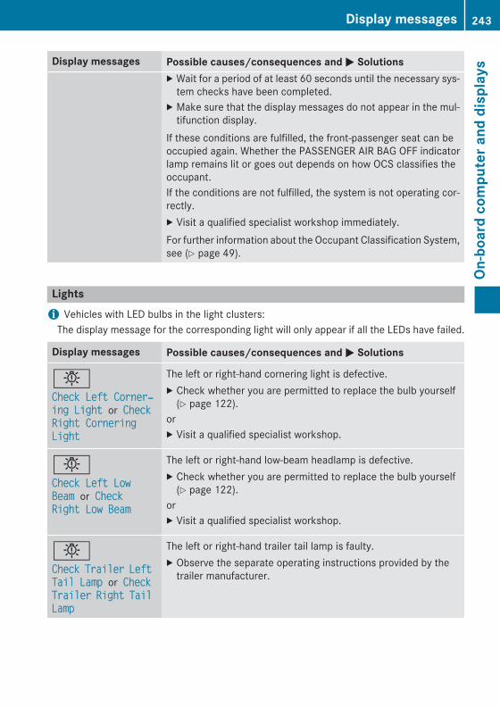
Display messages Possible causes/consequences and M SolutionsX Wait for a period of at least 60 seconds until the necessary sys-
tem checks have been completed.X Make sure that the display messages do not appear in the mul-
tifunction display.If these conditions are fulfilled, the front-passenger seat can beoccupied again. Whether the PASSENGER AIR BAG OFF indicatorlamp remains lit or goes out depends on how OCS classifies theoccupant.If the conditions are not fulfilled, the system is not operating cor-rectly.X Visit a qualified specialist workshop immediately.For further information about the Occupant Classification System,see (Y page 49).
Lightsi Vehicles with LED bulbs in the light clusters:
The display message for the corresponding light will only appear if all the LEDs have failed.
Display messages Possible causes/consequences and M Solutions
bCheck Left Corner‐ing Light or Check Right Cornering Light
The left or right-hand cornering light is defective.X Check whether you are permitted to replace the bulb yourself
(Y page 122).orX Visit a qualified specialist workshop.
bCheck Left Low Beam or Check Right Low Beam
The left or right-hand low-beam headlamp is defective.X Check whether you are permitted to replace the bulb yourself
(Y page 122).orX Visit a qualified specialist workshop.
bCheck Trailer Left Tail Lamp or Check Trailer Right Tail Lamp
The left or right-hand trailer tail lamp is faulty.X Observe the separate operating instructions provided by the
trailer manufacturer.
Display messages 243
On-b
oard
com
pute
r and
dis
play
s
Z
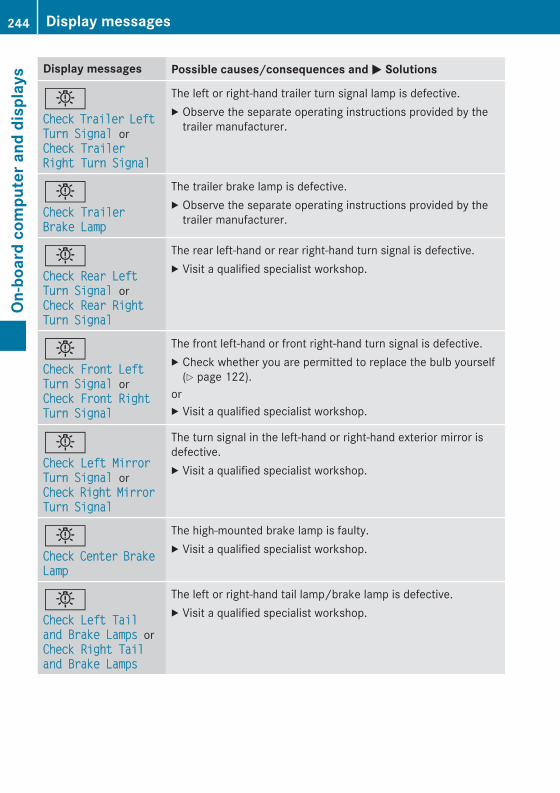
Display messages Possible causes/consequences and M Solutions
bCheck Trailer Left Turn Signal or Check Trailer Right Turn Signal
The left or right-hand trailer turn signal lamp is defective.X Observe the separate operating instructions provided by the
trailer manufacturer.
bCheck Trailer Brake Lamp
The trailer brake lamp is defective.X Observe the separate operating instructions provided by the
trailer manufacturer.
bCheck Rear Left Turn Signal or Check Rear Right Turn Signal
The rear left-hand or rear right-hand turn signal is defective.X Visit a qualified specialist workshop.
bCheck Front Left Turn Signal or Check Front Right Turn Signal
The front left-hand or front right-hand turn signal is defective.X Check whether you are permitted to replace the bulb yourself
(Y page 122).orX Visit a qualified specialist workshop.
bCheck Left Mirror Turn Signal or Check Right Mirror Turn Signal
The turn signal in the left-hand or right-hand exterior mirror isdefective.X Visit a qualified specialist workshop.
bCheck Center Brake Lamp
The high-mounted brake lamp is faulty.X Visit a qualified specialist workshop.
bCheck Left Tail and Brake Lamps or Check Right Tail and Brake Lamps
The left or right-hand tail lamp/brake lamp is defective.X Visit a qualified specialist workshop.
244 Display messagesOn
-boa
rd c
ompu
ter a
nd d
ispl
ays
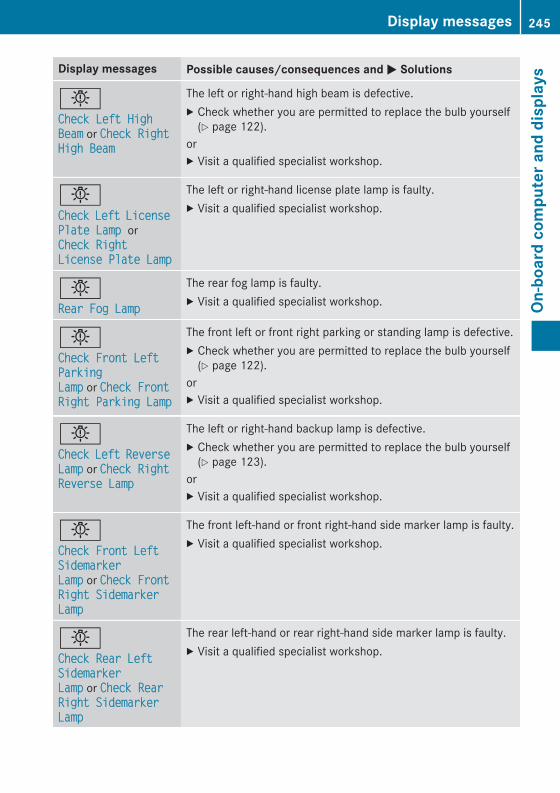
Display messages Possible causes/consequences and M Solutions
bCheck Left High Beam or Check Right High Beam
The left or right-hand high beam is defective.X Check whether you are permitted to replace the bulb yourself
(Y page 122).orX Visit a qualified specialist workshop.
bCheck Left License Plate Lamp or Check Right License Plate Lamp
The left or right-hand license plate lamp is faulty.X Visit a qualified specialist workshop.
bRear Fog Lamp
The rear fog lamp is faulty.X Visit a qualified specialist workshop.
bCheck Front Left Parking Lamp or Check Front Right Parking Lamp
The front left or front right parking or standing lamp is defective.X Check whether you are permitted to replace the bulb yourself
(Y page 122).orX Visit a qualified specialist workshop.
bCheck Left Reverse Lamp or Check Right Reverse Lamp
The left or right-hand backup lamp is defective.X Check whether you are permitted to replace the bulb yourself
(Y page 123).orX Visit a qualified specialist workshop.
bCheck Front Left Sidemarker Lamp or Check Front Right Sidemarker Lamp
The front left-hand or front right-hand side marker lamp is faulty.X Visit a qualified specialist workshop.
bCheck Rear Left Sidemarker Lamp or Check Rear Right Sidemarker Lamp
The rear left-hand or rear right-hand side marker lamp is faulty.X Visit a qualified specialist workshop.
Display messages 245
On-b
oard
com
pute
r and
dis
play
s
Z
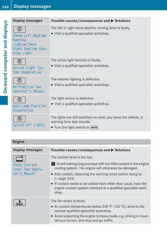
Display messages Possible causes/consequences and M Solutions
bCheck Left Daytime Running Light or Check Right Daytime Run‐ning Light
The left or right-hand daytime running lamp is faulty.X Visit a qualified specialist workshop.
bActive Light Sys‐tem Inoperative
The active light function is faulty.X Visit a qualified specialist workshop.
bMalfunction See Operator's Manual
The exterior lighting is defective.X Visit a qualified specialist workshop.
bAuto Lamp Function Inoperative
The light sensor is defective.X Visit a qualified specialist workshop.
bSwitch Off Lights
The lights are still switched on when you leave the vehicle. Awarning tone also sounds.X Turn the light switch to Ã.
Engine
Display messages Possible causes/consequences and M Solutions
+Check Coolant Level See Opera‐tor's Manual
The coolant level is too low.
! Avoid making long journeys with too little coolant in the enginecooling system. The engine will otherwise be damaged.
X Add coolant, observing the warning notes before doing so(Y page 303).
X If coolant needs to be added more often than usual, have theengine coolant system checked at a qualified specialist work-shop.
? The fan motor is faulty.X At coolant temperatures below 248 ‡ (120 †), drive to the
nearest qualified specialist workshop.X Avoid subjecting the engine to heavy loads, e.g. driving in moun-
tainous terrain, and stop-and-go traffic.
246 Display messagesOn
-boa
rd c
ompu
ter a
nd d
ispl
ays
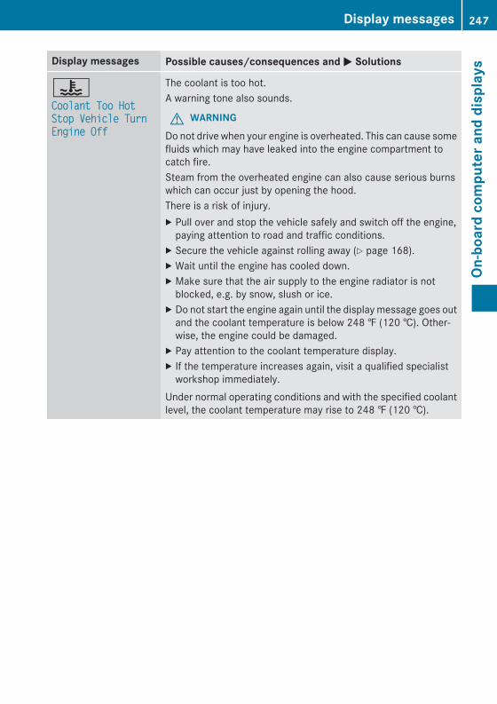
Display messages Possible causes/consequences and M Solutions
?Coolant Too Hot Stop Vehicle Turn Engine Off
The coolant is too hot.A warning tone also sounds.
G WARNINGDo not drive when your engine is overheated. This can cause somefluids which may have leaked into the engine compartment tocatch fire.Steam from the overheated engine can also cause serious burnswhich can occur just by opening the hood.There is a risk of injury.X Pull over and stop the vehicle safely and switch off the engine,
paying attention to road and traffic conditions.X Secure the vehicle against rolling away (Y page 168).X Wait until the engine has cooled down.X Make sure that the air supply to the engine radiator is not
blocked, e.g. by snow, slush or ice.X Do not start the engine again until the display message goes out
and the coolant temperature is below 248 ‡ (120 †). Other-wise, the engine could be damaged.
X Pay attention to the coolant temperature display.X If the temperature increases again, visit a qualified specialist
workshop immediately.Under normal operating conditions and with the specified coolantlevel, the coolant temperature may rise to 248 ‡ (120 †).
Display messages 247
On-b
oard
com
pute
r and
dis
play
s
Z
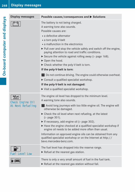
Display messages Possible causes/consequences and M Solutions
# The battery is not being charged.A warning tone also sounds.Possible causes are:Ra defective alternatorRa torn poly-V-beltRa malfunction in the electronicsX Pull over and stop the vehicle safely and switch off the engine,
paying attention to road and traffic conditions.X Secure the vehicle against rolling away (Y page 168).X Open the hood.X Check whether the poly-V-belt is torn.If the poly-V-belt is torn:
! Do not continue driving. The engine could otherwise overheat.X Consult a qualified specialist workshop.If the poly-V-belt is not damaged:X Visit a qualified specialist workshop.
4Check Engine Oil At Next Refueling
The engine oil level has dropped to the minimum level.A warning tone also sounds.
! Avoid long journeys with too little engine oil. The engine willotherwise be damaged.
X Check the oil level when next refueling, at the latest(Y page 301).
X If necessary, add engine oil (Y page 302).X Have the engine checked at a qualified specialist workshop if
engine oil needs to be added more often than usual.Information on approved engine oils can be obtained from anyqualified specialist workshop or on the Internet at http://bevo.mercedes-benz.com.
8Fuel Level Low
The fuel level has dropped into the reserve range.X Refuel at the nearest gas station.
C There is only a very small amount of fuel in the fuel tank.X Refuel at the nearest gas station without fail.
248 Display messagesOn
-boa
rd c
ompu
ter a
nd d
ispl
ays
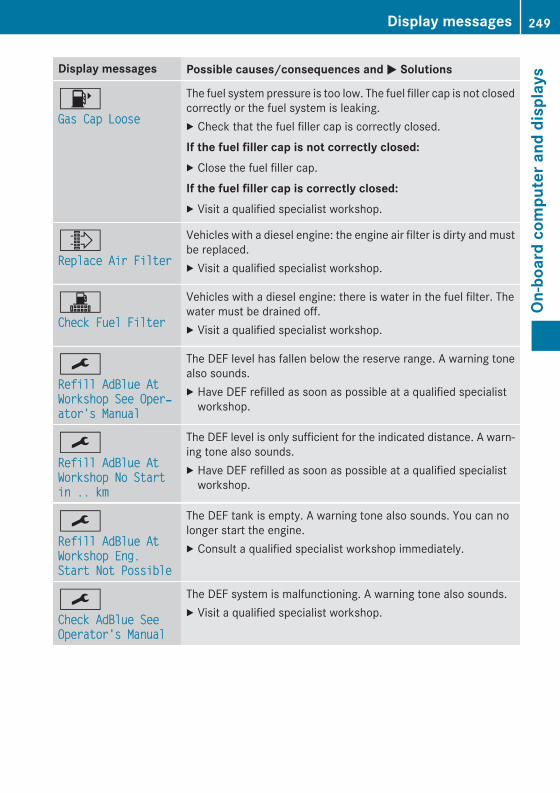
Display messages Possible causes/consequences and M Solutions
8Gas Cap Loose
The fuel system pressure is too low. The fuel filler cap is not closedcorrectly or the fuel system is leaking.X Check that the fuel filler cap is correctly closed.If the fuel filler cap is not correctly closed:X Close the fuel filler cap.If the fuel filler cap is correctly closed:X Visit a qualified specialist workshop.
¸Replace Air Filter
Vehicles with a diesel engine: the engine air filter is dirty and mustbe replaced.X Visit a qualified specialist workshop.
!Check Fuel Filter
Vehicles with a diesel engine: there is water in the fuel filter. Thewater must be drained off.X Visit a qualified specialist workshop.
¯Refill AdBlue At Workshop See Oper‐ator's Manual
The DEF level has fallen below the reserve range. A warning tonealso sounds.X Have DEF refilled as soon as possible at a qualified specialist
workshop.
¯Refill AdBlue At Workshop No Start in .. km
The DEF level is only sufficient for the indicated distance. A warn-ing tone also sounds.X Have DEF refilled as soon as possible at a qualified specialist
workshop.
¯Refill AdBlue At Workshop Eng. Start Not Possible
The DEF tank is empty. A warning tone also sounds. You can nolonger start the engine.X Consult a qualified specialist workshop immediately.
¯Check AdBlue See Operator's Manual
The DEF system is malfunctioning. A warning tone also sounds.X Visit a qualified specialist workshop.
Display messages 249
On-b
oard
com
pute
r and
dis
play
s
Z

Display messages Possible causes/consequences and M Solutions
¯Eng. Start Not Pos‐sible In ..km
The DEF system is malfunctioning. A warning tone also sounds.X Visit a qualified specialist workshop immediately.
¯Eng. Start Not Pos‐sible
The DEF system is malfunctioning. A warning tone also sounds.You can no longer start the engine.X Consult a qualified specialist workshop immediately.
Driving systems
Display messages Possible causes/consequences and M Solutions
ÀAttention Assist: Take a Break!
Based on certain criteria, ATTENTION ASSIST has detected fatigueor a lack of concentration on the part of the driver. A warning tonealso sounds.X If necessary, take a break.During long journeys, take regular breaks in good time so you getenough rest.
ÀAttention Assist Inoperative
ATTENTION ASSIST is inoperative.X Visit a qualified specialist workshop.
ëOff
The HOLD function is deactivated. The vehicle is skidding.A warning tone also sounds.X Reactivate the HOLD function later (Y page 184).
The HOLD function is deactivated. When the brake pedal is firmlydepressed, an activation condition is not fulfilled.A warning tone also sounds.X Check the activation conditions for the HOLD function
(Y page 184).
Radar Sensors Deac‐tivated See Opera‐tor's Manual
The radar sensor system is deactivated.X Switch on the radar sensor system (Y page 233).
250 Display messagesOn
-boa
rd c
ompu
ter a
nd d
ispl
ays
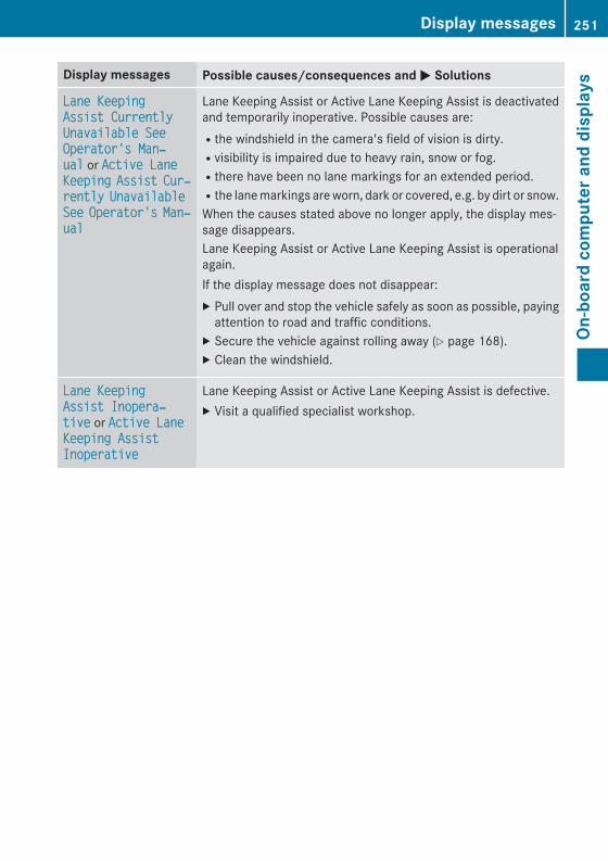
Display messages Possible causes/consequences and M Solutions
Lane Keeping Assist Currently Unavailable See Operator's Man‐ual or Active Lane Keeping Assist Cur‐rently Unavailable See Operator's Man‐ual
Lane Keeping Assist or Active Lane Keeping Assist is deactivatedand temporarily inoperative. Possible causes are:Rthe windshield in the camera's field of vision is dirty.Rvisibility is impaired due to heavy rain, snow or fog.Rthere have been no lane markings for an extended period.Rthe lane markings are worn, dark or covered, e.g. by dirt or snow.When the causes stated above no longer apply, the display mes-sage disappears.Lane Keeping Assist or Active Lane Keeping Assist is operationalagain.If the display message does not disappear:X Pull over and stop the vehicle safely as soon as possible, paying
attention to road and traffic conditions.X Secure the vehicle against rolling away (Y page 168).X Clean the windshield.
Lane Keeping Assist Inopera‐tive or Active Lane Keeping Assist Inoperative
Lane Keeping Assist or Active Lane Keeping Assist is defective.X Visit a qualified specialist workshop.
Display messages 251
On-b
oard
com
pute
r and
dis
play
s
Z
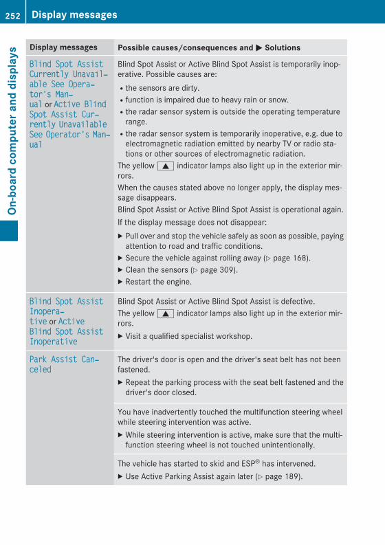
Display messages Possible causes/consequences and M Solutions
Blind Spot Assist Currently Unavail‐able See Opera‐tor's Man‐ual or Active Blind Spot Assist Cur‐rently Unavailable See Operator's Man‐ual
Blind Spot Assist or Active Blind Spot Assist is temporarily inop-erative. Possible causes are:Rthe sensors are dirty.Rfunction is impaired due to heavy rain or snow.Rthe radar sensor system is outside the operating temperature
range.Rthe radar sensor system is temporarily inoperative, e.g. due to
electromagnetic radiation emitted by nearby TV or radio sta-tions or other sources of electromagnetic radiation.
The yellow 9 indicator lamps also light up in the exterior mir-rors.When the causes stated above no longer apply, the display mes-sage disappears.Blind Spot Assist or Active Blind Spot Assist is operational again.If the display message does not disappear:X Pull over and stop the vehicle safely as soon as possible, paying
attention to road and traffic conditions.X Secure the vehicle against rolling away (Y page 168).X Clean the sensors (Y page 309).X Restart the engine.
Blind Spot Assist Inopera‐tive or Active Blind Spot Assist Inoperative
Blind Spot Assist or Active Blind Spot Assist is defective.The yellow 9 indicator lamps also light up in the exterior mir-rors.X Visit a qualified specialist workshop.
Park Assist Can‐celed
The driver's door is open and the driver's seat belt has not beenfastened.X Repeat the parking process with the seat belt fastened and the
driver's door closed.
You have inadvertently touched the multifunction steering wheelwhile steering intervention was active.X While steering intervention is active, make sure that the multi-
function steering wheel is not touched unintentionally.
The vehicle has started to skid and ESP® has intervened.X Use Active Parking Assist again later (Y page 189).
252 Display messagesOn
-boa
rd c
ompu
ter a
nd d
ispl
ays
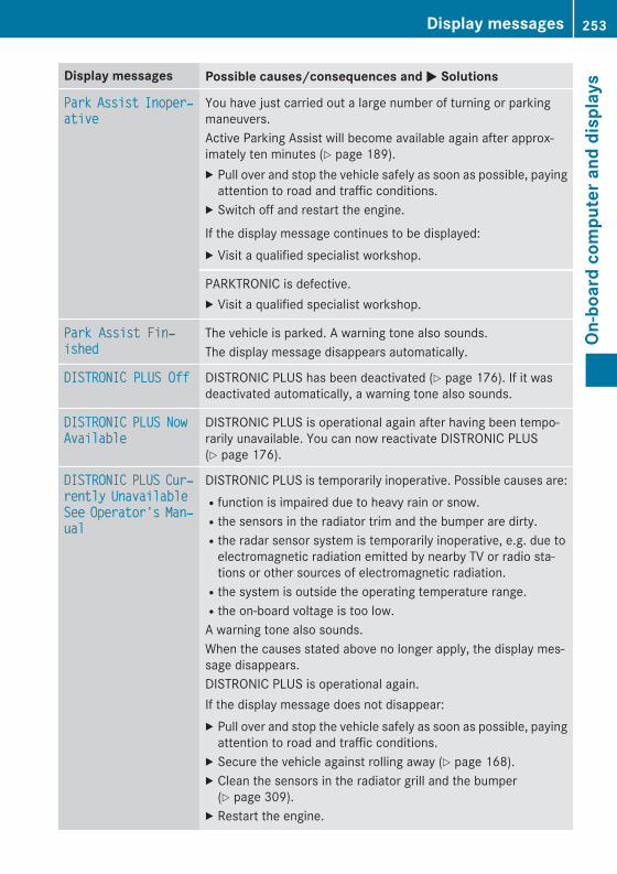
Display messages Possible causes/consequences and M Solutions
Park Assist Inoper‐ative
You have just carried out a large number of turning or parkingmaneuvers.Active Parking Assist will become available again after approx-imately ten minutes (Y page 189).X Pull over and stop the vehicle safely as soon as possible, paying
attention to road and traffic conditions.X Switch off and restart the engine.
If the display message continues to be displayed:X Visit a qualified specialist workshop.
PARKTRONIC is defective.X Visit a qualified specialist workshop.
Park Assist Fin‐ished
The vehicle is parked. A warning tone also sounds.The display message disappears automatically.
DISTRONIC PLUS Off DISTRONIC PLUS has been deactivated (Y page 176). If it wasdeactivated automatically, a warning tone also sounds.
DISTRONIC PLUS Now Available
DISTRONIC PLUS is operational again after having been tempo-rarily unavailable. You can now reactivate DISTRONIC PLUS(Y page 176).
DISTRONIC PLUS Cur‐rently Unavailable See Operator's Man‐ual
DISTRONIC PLUS is temporarily inoperative. Possible causes are:Rfunction is impaired due to heavy rain or snow.Rthe sensors in the radiator trim and the bumper are dirty.Rthe radar sensor system is temporarily inoperative, e.g. due to
electromagnetic radiation emitted by nearby TV or radio sta-tions or other sources of electromagnetic radiation.Rthe system is outside the operating temperature range.Rthe on-board voltage is too low.A warning tone also sounds.When the causes stated above no longer apply, the display mes-sage disappears.DISTRONIC PLUS is operational again.If the display message does not disappear:X Pull over and stop the vehicle safely as soon as possible, paying
attention to road and traffic conditions.X Secure the vehicle against rolling away (Y page 168).X Clean the sensors in the radiator grill and the bumper
(Y page 309).X Restart the engine.
Display messages 253
On-b
oard
com
pute
r and
dis
play
s
Z
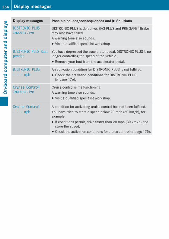
Display messages Possible causes/consequences and M Solutions
DISTRONIC PLUS Inoperative
DISTRONIC PLUS is defective. BAS PLUS and PRE‑SAFE® Brakemay also have failed.A warning tone also sounds.X Visit a qualified specialist workshop.
DISTRONIC PLUS Sus‐pended
You have depressed the accelerator pedal. DISTRONIC PLUS is nolonger controlling the speed of the vehicle.X Remove your foot from the accelerator pedal.
DISTRONIC PLUS- - - mph
An activation condition for DISTRONIC PLUS is not fulfilled.X Check the activation conditions for DISTRONIC PLUS
(Y page 176).
Cruise Control Inoperative
Cruise control is malfunctioning.A warning tone also sounds.X Visit a qualified specialist workshop.
Cruise Control- - - mph
A condition for activating cruise control has not been fulfilled.You have tried to store a speed below 20 mph (30 km/h), forexample.X If conditions permit, drive faster than 20 mph (30 km/h) and
store the speed.X Check the activation conditions for cruise control (Y page 175).
254 Display messagesOn
-boa
rd c
ompu
ter a
nd d
ispl
ays
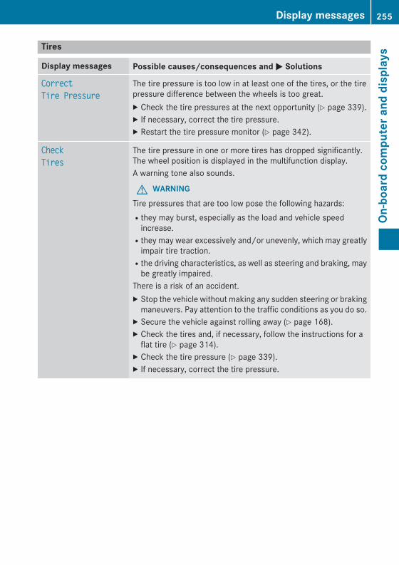
Tires
Display messages Possible causes/consequences and M Solutions
CorrectTire Pressure
The tire pressure is too low in at least one of the tires, or the tirepressure difference between the wheels is too great.X Check the tire pressures at the next opportunity (Y page 339).X If necessary, correct the tire pressure.X Restart the tire pressure monitor (Y page 342).
CheckTires
The tire pressure in one or more tires has dropped significantly.The wheel position is displayed in the multifunction display.A warning tone also sounds.
G WARNINGTire pressures that are too low pose the following hazards:Rthey may burst, especially as the load and vehicle speed
increase.Rthey may wear excessively and/or unevenly, which may greatly
impair tire traction.Rthe driving characteristics, as well as steering and braking, may
be greatly impaired.There is a risk of an accident.X Stop the vehicle without making any sudden steering or braking
maneuvers. Pay attention to the traffic conditions as you do so.X Secure the vehicle against rolling away (Y page 168).X Check the tires and, if necessary, follow the instructions for a
flat tire (Y page 314).X Check the tire pressure (Y page 339).X If necessary, correct the tire pressure.
Display messages 255
On-b
oard
com
pute
r and
dis
play
s
Z

Display messages Possible causes/consequences and M Solutions
WarningTire Malfunction
The tire pressure in one or more tires has dropped suddenly. Thewheel position is shown in the multifunction display.
G WARNINGDriving with a flat tire poses a risk of the following hazards:Ra flat tire affects the ability to steer or brake the vehicle.Ryou could lose control of the vehicle.Rcontinued driving with a flat tire will cause excessive heat build-
up and possibly a fire.There is a risk of an accident.X Stop the vehicle without making any sudden steering or braking
maneuvers. Pay attention to the traffic conditions as you do so.X Secure the vehicle against rolling away (Y page 168).X Check the tires and, if necessary, follow the instructions for a
flat tire (Y page 314).
Tire Press. MonitorCurrently Unavail‐able
Because there is interference from a strong source of radio waves,no signals from the tire pressure sensors are detected. The tirepressure monitor is temporarily malfunctioning.X Drive on.
The tire pressure monitor restarts automatically as soon as theproblem has been resolved.
TirePress. Sen‐sor(s) Missing
There is no signal from the tire pressure sensor of one or severalwheels. The pressure of the affected tire is not displayed in themultifunction display.X Have the faulty tire pressure sensor replaced at a qualified spe-
cialist workshop.
Tire Pressure Mon‐itor Inoperative No Wheel Sensors
The wheels mounted do not have a suitable tire pressure sensor.The tire pressure monitor is deactivated.X Mount wheels with suitable tire pressure sensors.
The tire pressure monitor is activated automatically after drivingfor a few minutes.
Tire pressure mon‐itorInoperative
The tire pressure monitor is faulty.X Visit a qualified specialist workshop.
256 Display messagesOn
-boa
rd c
ompu
ter a
nd d
ispl
ays
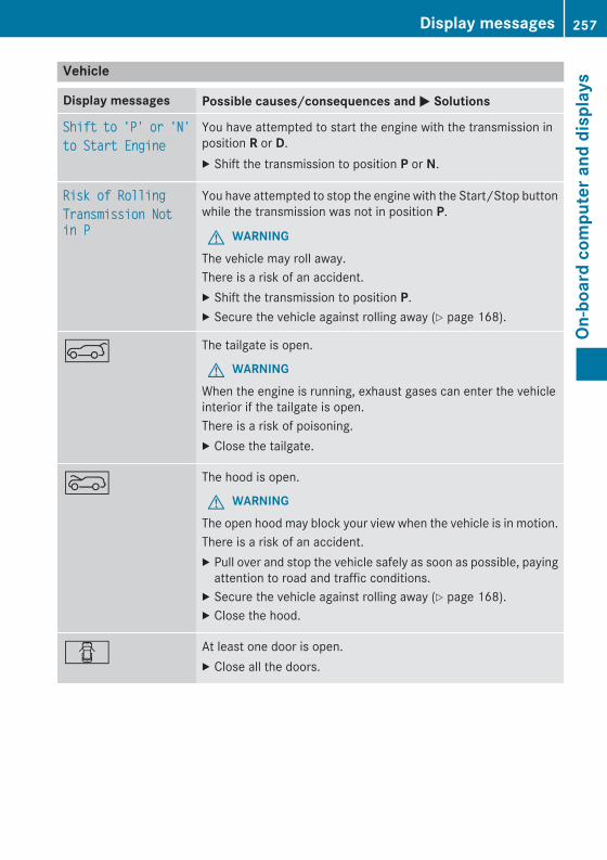
Vehicle
Display messages Possible causes/consequences and M Solutions
Shift to 'P' or 'N'to Start Engine
You have attempted to start the engine with the transmission inposition R or D.X Shift the transmission to position P or N.
Risk of RollingTransmission Not in P
You have attempted to stop the engine with the Start/Stop buttonwhile the transmission was not in position P.
G WARNINGThe vehicle may roll away.There is a risk of an accident.X Shift the transmission to position P.X Secure the vehicle against rolling away (Y page 168).
A The tailgate is open.
G WARNINGWhen the engine is running, exhaust gases can enter the vehicleinterior if the tailgate is open.There is a risk of poisoning.X Close the tailgate.
? The hood is open.
G WARNINGThe open hood may block your view when the vehicle is in motion.There is a risk of an accident.X Pull over and stop the vehicle safely as soon as possible, paying
attention to road and traffic conditions.X Secure the vehicle against rolling away (Y page 168).X Close the hood.
C At least one door is open.X Close all the doors.
Display messages 257
On-b
oard
com
pute
r and
dis
play
s
Z
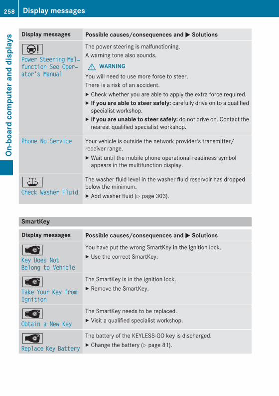
Display messages Possible causes/consequences and M Solutions
ÐPower Steering Mal‐function See Oper‐ator's Manual
The power steering is malfunctioning.A warning tone also sounds.
G WARNINGYou will need to use more force to steer.There is a risk of an accident.X Check whether you are able to apply the extra force required.X If you are able to steer safely: carefully drive on to a qualified
specialist workshop.X If you are unable to steer safely: do not drive on. Contact the
nearest qualified specialist workshop.
Phone No Service Your vehicle is outside the network provider's transmitter/receiver range.X Wait until the mobile phone operational readiness symbol
appears in the multifunction display.
¥Check Washer Fluid
The washer fluid level in the washer fluid reservoir has droppedbelow the minimum.X Add washer fluid (Y page 303).
SmartKey
Display messages Possible causes/consequences and M Solutions
ÂKey Does Not Belong to Vehicle
You have put the wrong SmartKey in the ignition lock.X Use the correct SmartKey.
ÂTake Your Key from Ignition
The SmartKey is in the ignition lock.X Remove the SmartKey.
ÂObtain a New Key
The SmartKey needs to be replaced.X Visit a qualified specialist workshop.
ÂReplace Key Battery
The battery of the KEYLESS-GO key is discharged.X Change the battery (Y page 81).
258 Display messagesOn
-boa
rd c
ompu
ter a
nd d
ispl
ays
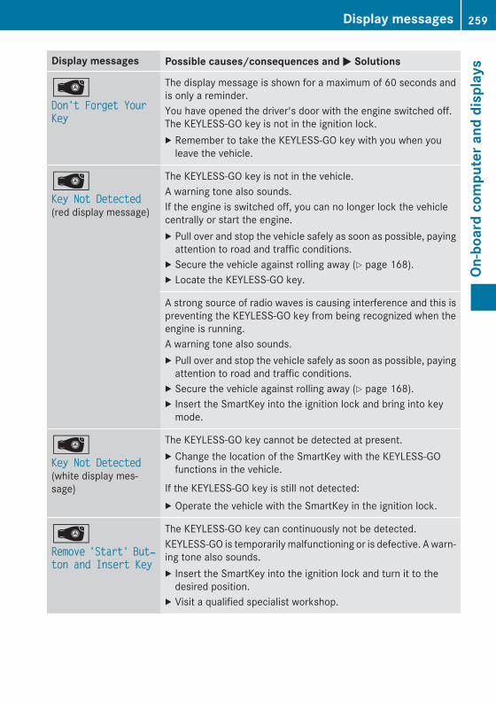
Display messages Possible causes/consequences and M Solutions
ÂDon't Forget Your Key
The display message is shown for a maximum of 60 seconds andis only a reminder.You have opened the driver's door with the engine switched off.The KEYLESS-GO key is not in the ignition lock.X Remember to take the KEYLESS-GO key with you when you
leave the vehicle.
ÂKey Not Detected (red display message)
The KEYLESS-GO key is not in the vehicle.A warning tone also sounds.If the engine is switched off, you can no longer lock the vehiclecentrally or start the engine.X Pull over and stop the vehicle safely as soon as possible, paying
attention to road and traffic conditions.X Secure the vehicle against rolling away (Y page 168).X Locate the KEYLESS-GO key.
A strong source of radio waves is causing interference and this ispreventing the KEYLESS-GO key from being recognized when theengine is running.A warning tone also sounds.X Pull over and stop the vehicle safely as soon as possible, paying
attention to road and traffic conditions.X Secure the vehicle against rolling away (Y page 168).X Insert the SmartKey into the ignition lock and bring into key
mode.
ÂKey Not Detected (white display mes-sage)
The KEYLESS-GO key cannot be detected at present.X Change the location of the SmartKey with the KEYLESS-GO
functions in the vehicle.
If the KEYLESS-GO key is still not detected:X Operate the vehicle with the SmartKey in the ignition lock.
ÂRemove 'Start' But‐ton and Insert Key
The KEYLESS-GO key can continuously not be detected.KEYLESS-GO is temporarily malfunctioning or is defective. A warn-ing tone also sounds.X Insert the SmartKey into the ignition lock and turn it to the
desired position.X Visit a qualified specialist workshop.
Display messages 259
On-b
oard
com
pute
r and
dis
play
s
Z
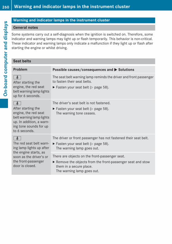
Warning and indicator lamps in the instrument cluster
General notesSome systems carry out a self-diagnosis when the ignition is switched on. Therefore, someindicator and warning lamps may light up or flash temporarily. This behavior is non-critical.These indicator and warning lamps only indicate a malfunction if they light up or flash afterstarting the engine or whilst driving.
Seat belts
Problem Possible causes/consequences and M Solutions
ü
After starting theengine, the red seatbelt warning lamp lightsup for 6 seconds.
The seat belt warning lamp reminds the driver and front passengerto fasten their seat belts.X Fasten your seat belt (Y page 58).
ü
After starting theengine, the red seatbelt warning lamp lightsup. In addition, a warn-ing tone sounds for upto 6 seconds.
The driver's seat belt is not fastened.X Fasten your seat belt (Y page 58).
The warning tone ceases.
ü
The red seat belt warn-ing lamp lights up afterthe engine starts, assoon as the driver's orthe front-passengerdoor is closed.
The driver or front passenger has not fastened their seat belt.X Fasten your seat belt (Y page 58).
The warning lamp goes out.
There are objects on the front-passenger seat.X Remove the objects from the front-passenger seat and stow
them in a secure place.The warning lamp goes out.
260 Warning and indicator lamps in the instrument clusterOn
-boa
rd c
ompu
ter a
nd d
ispl
ays
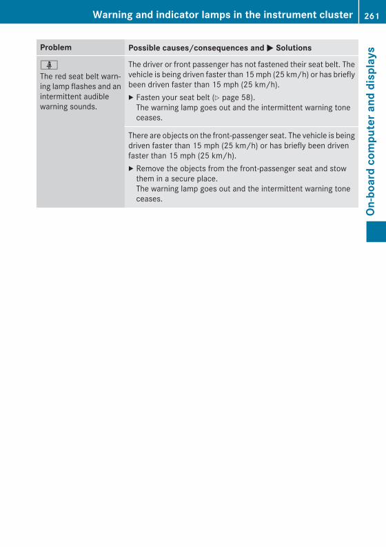
Problem Possible causes/consequences and M Solutions
ü
The red seat belt warn-ing lamp flashes and anintermittent audiblewarning sounds.
The driver or front passenger has not fastened their seat belt. Thevehicle is being driven faster than 15 mph (25 km/h) or has brieflybeen driven faster than 15 mph (25 km/h).X Fasten your seat belt (Y page 58).
The warning lamp goes out and the intermittent warning toneceases.
There are objects on the front-passenger seat. The vehicle is beingdriven faster than 15 mph (25 km/h) or has briefly been drivenfaster than 15 mph (25 km/h).X Remove the objects from the front-passenger seat and stow
them in a secure place.The warning lamp goes out and the intermittent warning toneceases.
Warning and indicator lamps in the instrument cluster 261
On-b
oard
com
pute
r and
dis
play
s
Z

Safety systems
Problem Possible causes/consequences and M Solutions
$ (USA only)J (Canada only)The red brake systemwarning lamp comes onwhile the engine is run-ning. A warning tonealso sounds.
There is not enough brake fluid in the brake fluid reservoir.
G WARNINGThe braking effect may be impaired.There is a risk of an accident.X Pull over and stop the vehicle safely as soon as possible, paying
attention to road and traffic conditions. Do not continue drivingunder any circumstances.
X Secure the vehicle against rolling away (Y page 168).X Do not add brake fluid. Adding more will not remedy the mal-
function.X Consult a qualified specialist workshop.X Observe the additional display messages in the multifunction
display.
!
The yellow ABS warninglamp is lit while theengine is running.
ABS (Anti-lock Braking System) is deactivated due to a malfunc-tion. BAS (Brake Assist), BAS PLUS, ESP® (Electronic StabilityProgram), PRE‑SAFE®, PRE‑SAFE® Brake, the HOLD function, hillstart assist and ESP® trailer stabilization are therefore also deac-tivated, for example.ATTENTION ASSIST is deactivated.
G WARNINGThe brake system continues to function normally, but without thefunctions listed above. The wheels could therefore lock if youbrake hard, for example.The steerability and braking characteristics may be severely affec-ted. The braking distance in an emergency braking situation canincrease.If ESP® is not operational, ESP® is unable to stabilize the vehicle.There is an increased risk of skidding and an accident.X Observe the additional display messages in the multifunction
display.X Drive on carefully.X Visit a qualified specialist workshop.If the ABS control unit is faulty, there is also a possibility that othersystems, such as the navigation system or the automatic trans-mission, will not be available.
262 Warning and indicator lamps in the instrument clusterOn
-boa
rd c
ompu
ter a
nd d
ispl
ays
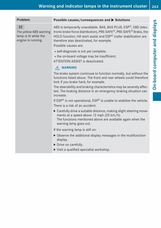
Problem Possible causes/consequences and M Solutions
!
The yellow ABS warninglamp is lit while theengine is running.
ABS is temporarily unavailable. BAS, BAS PLUS, ESP®, EBD (elec-tronic brake force distribution), PRE‑SAFE®, PRE‑SAFE® Brake, theHOLD function, hill start assist and ESP® trailer stabilization aretherefore also deactivated, for example.Possible causes are:Rself-diagnosis is not yet complete.Rthe on-board voltage may be insufficient.ATTENTION ASSIST is deactivated.
G WARNINGThe brake system continues to function normally, but without thefunctions listed above. The front and rear wheels could thereforelock if you brake hard, for example.The steerability and braking characteristics may be severely affec-ted. The braking distance in an emergency braking situation canincrease.If ESP® is not operational, ESP® is unable to stabilize the vehicle.There is a risk of an accident.X Carefully drive a suitable distance, making slight steering move-
ments at a speed above 12 mph (20 km/h).The functions mentioned above are available again when thewarning lamp goes out.
If the warning lamp is still on:X Observe the additional display messages in the multifunction
display.X Drive on carefully.X Visit a qualified specialist workshop.
Warning and indicator lamps in the instrument cluster 263
On-b
oard
com
pute
r and
dis
play
s
Z
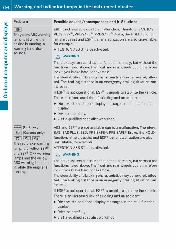
Problem Possible causes/consequences and M Solutions
!
The yellow ABS warninglamp is lit while theengine is running. Awarning tone alsosounds.
EBD is not available due to a malfunction. Therefore, BAS, BASPLUS, ESP®, PRE-SAFE®, PRE-SAFE® Brake, the HOLD function,hill start assist and ESP® trailer stabilization are also unavailable,for example.ATTENTION ASSIST is deactivated.
G WARNINGThe brake system continues to function normally, but without thefunctions listed above. The front and rear wheels could thereforelock if you brake hard, for example.The steerability and braking characteristics may be severely affec-ted. The braking distance in an emergency braking situation canincrease.If ESP® is not operational, ESP® is unable to stabilize the vehicle.There is an increased risk of skidding and an accident.X Observe the additional display messages in the multifunction
display.X Drive on carefully.X Visit a qualified specialist workshop.
$ (USA only)J (Canada only)÷ å !The red brake warninglamp, the yellow ESP®
and ESP® OFF warninglamps and the yellowABS warning lamp arelit while the engine isrunning.
ABS and ESP® are not available due to a malfunction. Therefore,BAS, BAS PLUS, EBD, PRE-SAFE®, PRE-SAFE® Brake, the HOLDfunction, hill start assist and ESP® trailer stabilization are alsounavailable, for example.ATTENTION ASSIST is deactivated.
G WARNINGThe brake system continues to function normally, but without thefunctions listed above. The front and rear wheels could thereforelock if you brake hard, for example.The steerability and braking characteristics may be severely affec-ted. The braking distance in an emergency braking situation canincrease.If ESP® is not operational, ESP® is unable to stabilize the vehicle.There is an increased risk of skidding and an accident.X Observe the additional display messages in the multifunction
display.X Drive on carefully.X Visit a qualified specialist workshop.
264 Warning and indicator lamps in the instrument clusterOn
-boa
rd c
ompu
ter a
nd d
ispl
ays
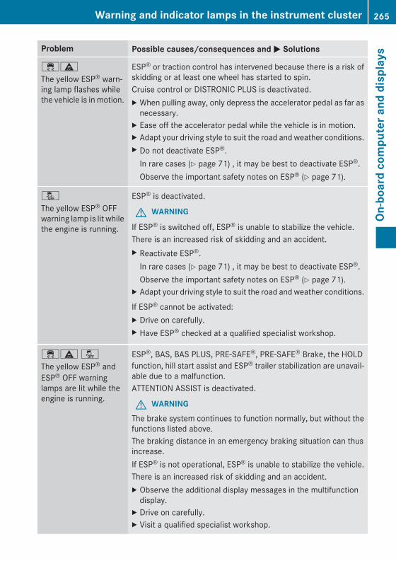
Problem Possible causes/consequences and M Solutions
֊
The yellow ESP® warn-ing lamp flashes whilethe vehicle is in motion.
ESP® or traction control has intervened because there is a risk ofskidding or at least one wheel has started to spin.Cruise control or DISTRONIC PLUS is deactivated.X When pulling away, only depress the accelerator pedal as far as
necessary.X Ease off the accelerator pedal while the vehicle is in motion.X Adapt your driving style to suit the road and weather conditions.X Do not deactivate ESP®.
In rare cases (Y page 71) , it may be best to deactivate ESP®.Observe the important safety notes on ESP® (Y page 71).
å
The yellow ESP® OFFwarning lamp is lit whilethe engine is running.
ESP® is deactivated.
G WARNING
If ESP® is switched off, ESP® is unable to stabilize the vehicle.There is an increased risk of skidding and an accident.X Reactivate ESP®.
In rare cases (Y page 71) , it may be best to deactivate ESP®.Observe the important safety notes on ESP® (Y page 71).
X Adapt your driving style to suit the road and weather conditions.
If ESP® cannot be activated:X Drive on carefully.X Have ESP® checked at a qualified specialist workshop.
÷ä åThe yellow ESP® andESP® OFF warninglamps are lit while theengine is running.
ESP®, BAS, BAS PLUS, PRE‑SAFE®, PRE‑SAFE® Brake, the HOLDfunction, hill start assist and ESP® trailer stabilization are unavail-able due to a malfunction.ATTENTION ASSIST is deactivated.
G WARNINGThe brake system continues to function normally, but without thefunctions listed above.The braking distance in an emergency braking situation can thusincrease.If ESP® is not operational, ESP® is unable to stabilize the vehicle.There is an increased risk of skidding and an accident.X Observe the additional display messages in the multifunction
display.X Drive on carefully.X Visit a qualified specialist workshop.
Warning and indicator lamps in the instrument cluster 265
On-b
oard
com
pute
r and
dis
play
s
Z
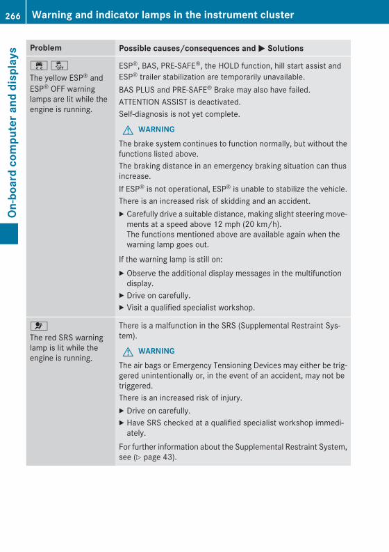
Problem Possible causes/consequences and M Solutions
÷ åThe yellow ESP® andESP® OFF warninglamps are lit while theengine is running.
ESP®, BAS, PRE-SAFE®, the HOLD function, hill start assist andESP® trailer stabilization are temporarily unavailable.BAS PLUS and PRE‑SAFE® Brake may also have failed.ATTENTION ASSIST is deactivated.Self-diagnosis is not yet complete.
G WARNINGThe brake system continues to function normally, but without thefunctions listed above.The braking distance in an emergency braking situation can thusincrease.If ESP® is not operational, ESP® is unable to stabilize the vehicle.There is an increased risk of skidding and an accident.X Carefully drive a suitable distance, making slight steering move-
ments at a speed above 12 mph (20 km/h).The functions mentioned above are available again when thewarning lamp goes out.
If the warning lamp is still on:X Observe the additional display messages in the multifunction
display.X Drive on carefully.X Visit a qualified specialist workshop.
6
The red SRS warninglamp is lit while theengine is running.
There is a malfunction in the SRS (Supplemental Restraint Sys-tem).
G WARNINGThe air bags or Emergency Tensioning Devices may either be trig-gered unintentionally or, in the event of an accident, may not betriggered.There is an increased risk of injury.X Drive on carefully.X Have SRS checked at a qualified specialist workshop immedi-
ately.For further information about the Supplemental Restraint System,see (Y page 43).
266 Warning and indicator lamps in the instrument clusterOn
-boa
rd c
ompu
ter a
nd d
ispl
ays
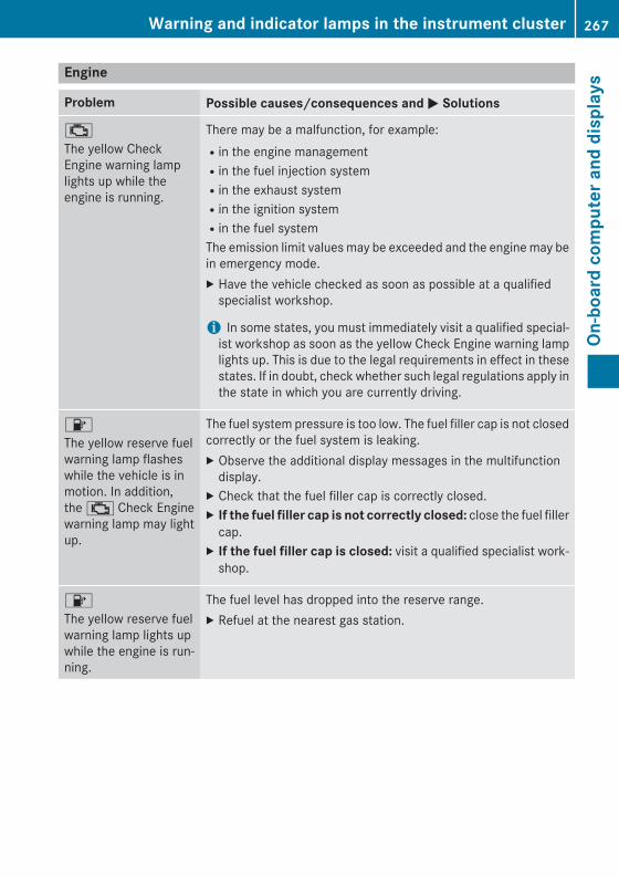
Engine
Problem Possible causes/consequences and M Solutions
;
The yellow CheckEngine warning lamplights up while theengine is running.
There may be a malfunction, for example:Rin the engine managementRin the fuel injection systemRin the exhaust systemRin the ignition systemRin the fuel systemThe emission limit values may be exceeded and the engine may bein emergency mode.X Have the vehicle checked as soon as possible at a qualified
specialist workshop.
i In some states, you must immediately visit a qualified special-ist workshop as soon as the yellow Check Engine warning lamplights up. This is due to the legal requirements in effect in thesestates. If in doubt, check whether such legal regulations apply inthe state in which you are currently driving.
8
The yellow reserve fuelwarning lamp flasheswhile the vehicle is inmotion. In addition,the ; Check Enginewarning lamp may lightup.
The fuel system pressure is too low. The fuel filler cap is not closedcorrectly or the fuel system is leaking.X Observe the additional display messages in the multifunction
display.X Check that the fuel filler cap is correctly closed.X If the fuel filler cap is not correctly closed: close the fuel filler
cap.X If the fuel filler cap is closed: visit a qualified specialist work-
shop.
8
The yellow reserve fuelwarning lamp lights upwhile the engine is run-ning.
The fuel level has dropped into the reserve range.X Refuel at the nearest gas station.
Warning and indicator lamps in the instrument cluster 267
On-b
oard
com
pute
r and
dis
play
s
Z
Problem Possible causes/consequences and M Solutions
?
The red coolant warn-ing lamp lights up whilethe engine is runningand the coolant tem-perature gauge is at thestart of the scale.
The temperature sensor for the coolant temperature gauge isdefective.The coolant temperature is no longer being monitored. There is arisk of engine damage if the coolant temperature is too high.X Pull over and stop the vehicle safely and switch off the engine,
paying attention to road and traffic conditions. Do not continuedriving under any circumstances.
X Secure the vehicle against rolling away (Y page 168).X Consult a qualified specialist workshop.
268 Warning and indicator lamps in the instrument clusterOn
-boa
rd c
ompu
ter a
nd d
ispl
ays
Problem Possible causes/consequences and M Solutions
?
The red coolant warn-ing lamp comes onwhile the engine is run-ning.
The coolant level is too low.If the coolant level is correct, the airflow to the engine radiator maybe blocked or the electric engine radiator fan may be malfunc-tioning.The coolant is too hot and the engine is no longer being cooledsufficiently.X Observe the additional display messages in the multifunction
display.X Pull over and stop the vehicle safely and switch off the engine,
paying attention to road and traffic conditions.X Secure the vehicle against rolling away (Y page 168).X Wait until the engine has cooled down.X Make sure that the air supply to the engine radiator is not
blocked, e.g. by snow, slush or ice.X Check the coolant level and add coolant (Y page 303). Observe
the warning notes.X If you need to add coolant more often than usual, have the
engine coolant system checked.X At coolant temperatures below 248 ‡ (120 †), drive to the
nearest qualified specialist workshop.X Avoid subjecting the engine to heavy loads, e.g. driving in moun-
tainous terrain, and stop-and-go traffic.
?
The red coolant warn-ing lamp comes onwhile the engine is run-ning. A warning tonealso sounds.
The coolant temperature has exceeded 248 ‡ (120 †). The air-flow to the engine radiator may be blocked or the coolant level maybe too low.
G WARNINGThe engine is not being cooled sufficiently and may be damaged.Do not drive when your engine is overheated. This can cause somefluids which may have leaked into the engine compartment tocatch fire.Steam from the overheated engine can also cause serious burnswhich can occur just by opening the hood.There is a risk of injury.X Observe the additional display messages in the multifunction
display.X Pull over and stop the vehicle safely and switch off the engine,
paying attention to road and traffic conditions.X Secure the vehicle against rolling away (Y page 168).X Wait until the engine has cooled down.
Warning and indicator lamps in the instrument cluster 269
On-b
oard
com
pute
r and
dis
play
s
Z
Problem Possible causes/consequences and M SolutionsX Make sure that the air supply to the engine radiator is not
blocked, e.g. by snow, slush or ice.X Check the coolant level and add coolant (Y page 303). Observe
the warning notes.X If you need to add coolant more often than usual, have the
engine coolant system checked.X At coolant temperatures below 248 ‡ (120 †), drive to the
nearest qualified specialist workshop.X Avoid subjecting the engine to heavy loads, e.g. driving in moun-
tainous terrain, and stop-and-go traffic.
Driving systems
Problem Possible causes/consequences and M Solutions
·
The red distance warn-ing lamp lights up whilethe vehicle is in motion.A warning tone alsosounds.
G WARNINGYou are approaching a vehicle or a stationary obstacle in your lineof travel at too high a speed.There is a risk of an accident.X Be prepared to brake immediately.X Pay careful attention to the traffic situation. You may have to
brake or take evasive action.More information about DISTRONIC PLUS (Y page 176) andPRE‑SAFE® Brake (Y page 73).
270 Warning and indicator lamps in the instrument clusterOn
-boa
rd c
ompu
ter a
nd d
ispl
ays
Tires
Problem Possible causes/consequences and M Solutions
h
The yellow tire pressuremonitor warning lamp(pressure loss/malfunction) is lit.
The tire pressure monitor has detected a loss of pressure in atleast one of the tires.
G WARNINGWith tire pressures which are too low, there is a risk of the fol-lowing hazards:Rthey may burst, especially as the load and vehicle speed
increase.Rthey may wear excessively and/or unevenly, which may greatly
impair tire traction.Rthe driving characteristics, as well as steering and braking, may
be greatly impaired.There is a risk of an accident.
X Stop the vehicle without making any sudden steering or brakingmaneuvers. Pay attention to the traffic conditions as you do so.
X Secure the vehicle against rolling away (Y page 168).X Observe the additional display messages in the multifunction
display.X Check the tires and, if necessary, follow the instructions for a
flat tire (Y page 314).X Check the tire pressure (Y page 339).X If necessary, correct the tire pressure.
h
The yellow tire pressuremonitor warning lamp(pressure loss/malfunction) flashes forapproximately oneminute and thenremains lit.
The tire pressure monitor is faulty.
G WARNINGThe system is possibly unable to recognize or register low tirepressure.There is a risk of an accident.X Observe the additional display messages in the multifunction
display.X Visit a qualified specialist workshop.
Warning and indicator lamps in the instrument cluster 271
On-b
oard
com
pute
r and
dis
play
s
Z

272

Useful information ............................ 274Loading guidelines ............................ 274Stowage areas ................................... 275Features ............................................. 282
273
Stow
age
and
feat
ures
Useful information
i This Operator's Manual describes allmodels and all standard and optional equip-ment of your vehicle available at the time ofpublication of the Operator's Manual.Country-specific differences are possible.Please note that your vehicle may not beequipped with all features described. Thisalso applies to safety-related systems andfunctions.
i Read the information on qualified special-ist workshops (Y page 27).
Loading guidelines
G WARNINGIf objects, luggage or loads are not secured ornot secured sufficiently, they could slip, tipover or be flung around and thereby hit vehicleoccupants. There is a risk of injury, particu-larly in the event of sudden braking or a sud-den change in direction.Always store objects so that they cannot beflung around. Secure objects, luggage orloads against slipping or tipping before thejourney.
G WARNINGCombustion engines emit poisonous exhaustgases such as carbon monoxide. If the tailgateis open when the engine is running, particu-larly if the vehicle is moving, exhaust fumescould enter the passenger compartment.There is a risk of poisoning.Turn off the engine before opening the tail-gate. Never drive with the tailgate open.
G WARNINGThe exhaust tail pipe and tail pipe trim canbecome very hot. If you come into contactwith these parts of the vehicle, you could burnyourself. There is a risk of injury.Always be particularly careful around theexhaust tail pipe and the tail pipe trim. Allow
these components to cool down before touch-ing them.
The gross vehicle weight (GVW) is the vehicleweight including fuel, vehicle tool kit, sparewheel, installed accessories, vehicle occu-pants and luggage/cargo.The gross load limit and the gross vehicleweight rating (GVWR) for your vehicle mustnever be exceeded. The gross load limit andthe GVWR are specified on the vehicle iden-tification plate on the B-pillar of the driver'sdoor (Y page 343).The load must also be distributed so that theweight on each axle never exceeds the grossaxle weight rating (GAWR) for the front andrear axles. The specifications for GVWR andGAWR are on the vehicle identification plateon the B-pillar of the driver's door(Y page 343).Further information can be found in the"Loading the vehicle" section (Y page 343).The handling characteristics of a laden vehi-cle are dependent on the distribution of theload within the vehicle. For this reason, youshould observe the following notes whentransporting a load:RThe cargo compartment is the preferred
place to carry objects.RPosition heavy loads as far forwards as pos-
sible and as low down in the cargo com-partment as possible.RThe load must not protrude above the
upper edge of the seat backrests.RAlways place the load against the rear or
front seat backrests. Make sure that theseat backrests are securely locked intoplace.RAlways place the load behind unoccupied
seats if possible.RUse the cargo tie-down rings and the parcel
nets to transport loads and luggage.RUse cargo tie-down rings and fastening
materials appropriate for the weight andsize of the load.
274 Loading guidelinesSt
owag
e an
d fe
atur
es
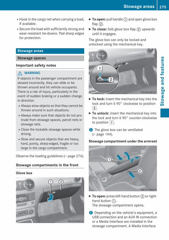
RHook in the cargo net when carrying a load,if available.RSecure the load with sufficiently strong and
wear-resistant tie-downs. Pad sharp edgesfor protection.
Stowage areas
Stowage spaces
Important safety notes
G WARNINGIf objects in the passenger compartment arestowed incorrectly, they can slide or bethrown around and hit vehicle occupants.There is a risk of injury, particularly in theevent of sudden braking or a sudden changein direction.RAlways stow objects so that they cannot be
thrown around in such situations.RAlways make sure that objects do not pro-
trude from stowage spaces, parcel nets orstowage nets.RClose the lockable stowage spaces while
driving.RStow and secure objects that are heavy,
hard, pointy, sharp-edged, fragile or toolarge in the cargo compartment.
Observe the loading guidelines (Y page 274).
Stowage compartments in the front
Glove box
X To open: pull handle : and open glove boxflap ;.
X To close: fold glove box flap ; upwardsuntil it engages.
The glove box can only be locked andunlocked using the mechanical key.
X To lock: insert the mechanical key into thelock and turn it 90° clockwise to position2.
X To unlock: insert the mechanical key intothe lock and turn it 90° counter-clockwiseto position 1.
i The glove box can be ventilated(Y page 144).
Stowage compartment under the armrest
X To open: press left-hand button ; or right-hand button :.The stowage compartment opens.
i Depending on the vehicle's equipment, aUSB connection and an AUX IN connectionor a Media Interface are installed in thestowage compartment. A Media Interface
Stowage areas 275
Stow
age
and
feat
ures
Z
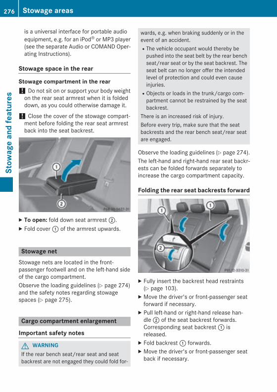
is a universal interface for portable audioequipment, e.g. for an iPod® or MP3 player(see the separate Audio or COMAND Oper-ating Instructions).
Stowage space in the rear
Stowage compartment in the rear! Do not sit on or support your body weight
on the rear seat armrest when it is foldeddown, as you could otherwise damage it.
! Close the cover of the stowage compart-ment before folding the rear seat armrestback into the seat backrest.
X To open: fold down seat armrest ;.X Fold cover : of the armrest upwards.
Stowage netStowage nets are located in the front-passenger footwell and on the left-hand sideof the cargo compartment.Observe the loading guidelines (Y page 274)and the safety notes regarding stowagespaces (Y page 275).
Cargo compartment enlargement
Important safety notes
G WARNINGIf the rear bench seat/rear seat and seatbackrest are not engaged they could fold for-
wards, e.g. when braking suddenly or in theevent of an accident.RThe vehicle occupant would thereby be
pushed into the seat belt by the rear benchseat/rear seat or by the seat backrest. Theseat belt can no longer offer the intendedlevel of protection and could even causeinjuries.RObjects or loads in the trunk/cargo com-
partment cannot be restrained by the seatbackrest.
There is an increased risk of injury.Before every trip, make sure that the seatbackrests and the rear bench seat/rear seatare engaged.
Observe the loading guidelines (Y page 274).The left-hand and right-hand rear seat backr-ests can be folded forwards separately toincrease the cargo compartment capacity.
Folding the rear seat backrests forward
X Fully insert the backrest head restraints(Y page 103).
X Move the driver's or front-passenger seatforward if necessary.
X Pull left-hand or right-hand release han-dle ; of the seat backrest forwards.Corresponding seat backrest : isreleased.
X Fold backrest : forwards.X Move the driver's or front-passenger seat
back if necessary.
276 Stowage areasSt
owag
e an
d fe
atur
es
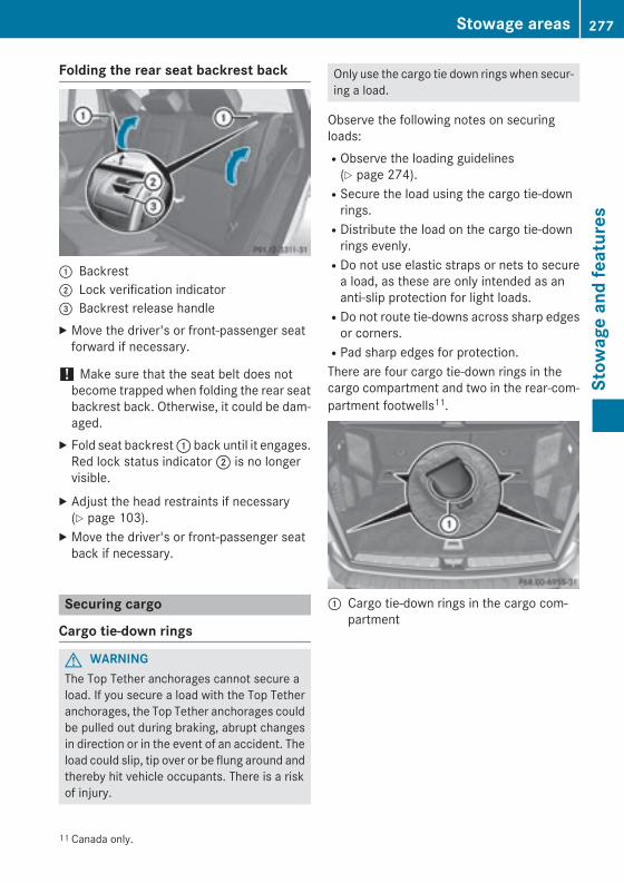
Folding the rear seat backrest back
: Backrest; Lock verification indicator= Backrest release handleX Move the driver's or front-passenger seat
forward if necessary.
! Make sure that the seat belt does notbecome trapped when folding the rear seatbackrest back. Otherwise, it could be dam-aged.
X Fold seat backrest : back until it engages.Red lock status indicator ; is no longervisible.
X Adjust the head restraints if necessary(Y page 103).
X Move the driver's or front-passenger seatback if necessary.
Securing cargo
Cargo tie-down rings
G WARNINGThe Top Tether anchorages cannot secure aload. If you secure a load with the Top Tetheranchorages, the Top Tether anchorages couldbe pulled out during braking, abrupt changesin direction or in the event of an accident. Theload could slip, tip over or be flung around andthereby hit vehicle occupants. There is a riskof injury.
Only use the cargo tie down rings when secur-ing a load.
Observe the following notes on securingloads:RObserve the loading guidelines
(Y page 274).RSecure the load using the cargo tie-down
rings.RDistribute the load on the cargo tie-down
rings evenly.RDo not use elastic straps or nets to secure
a load, as these are only intended as ananti-slip protection for light loads.RDo not route tie-downs across sharp edges
or corners.RPad sharp edges for protection.There are four cargo tie-down rings in thecargo compartment and two in the rear-com-partment footwells11.
: Cargo tie-down rings in the cargo com-partment
11 Canada only.
Stowage areas 277
Stow
age
and
feat
ures
Z
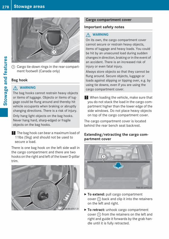
: Cargo tie-down rings in the rear-compart-ment footwell (Canada only)
Bag hook
G WARNINGThe bag hooks cannot restrain heavy objectsor items of luggage. Objects or items of lug-gage could be flung around and thereby hitvehicle occupants when braking or abruptlychanging directions. There is a risk of injury.Only hang light objects on the bag hooks.Never hang hard, sharp-edged or fragileobjects on the bag hooks.
! The bag hook can bear a maximum load of11lbs (5kg) and should not be used tosecure a load.
There is one bag hook on the left side wall inthe cargo compartment and there are twohooks on the right and left of the lower D-pillartrim.
Cargo compartment cover
Important safety notes
G WARNINGOn its own, the cargo compartment covercannot secure or restrain heavy objects,items of luggage and heavy loads. You couldbe hit by an unsecured load during suddenchanges in direction, braking or in the event ofan accident. There is an increased risk ofinjury or even fatal injury.Always store objects so that they cannot beflung around. Secure objects, luggage orloads against slipping or tipping over, e.g. byusing tie downs, even if you are using thecargo compartment cover.
! When loading the vehicle, make sure thatyou do not stack the load in the cargo com-partment higher than the lower edge of theside windows. Do not place heavy objectson top of the cargo compartment cover.
The cargo compartment cover is locatedbehind the rear bench seat backrest.
Extending/retracting the cargo com-partment cover
X To extend: pull cargo compartmentcover : back and clip it into the retainerson the left and right.
X To retract: unhook cargo compartmentcover : from the retainers on the left andright and guide it forwards by the grab han-dle until it is fully retracted.
278 Stowage areasSt
owag
e an
d fe
atur
es
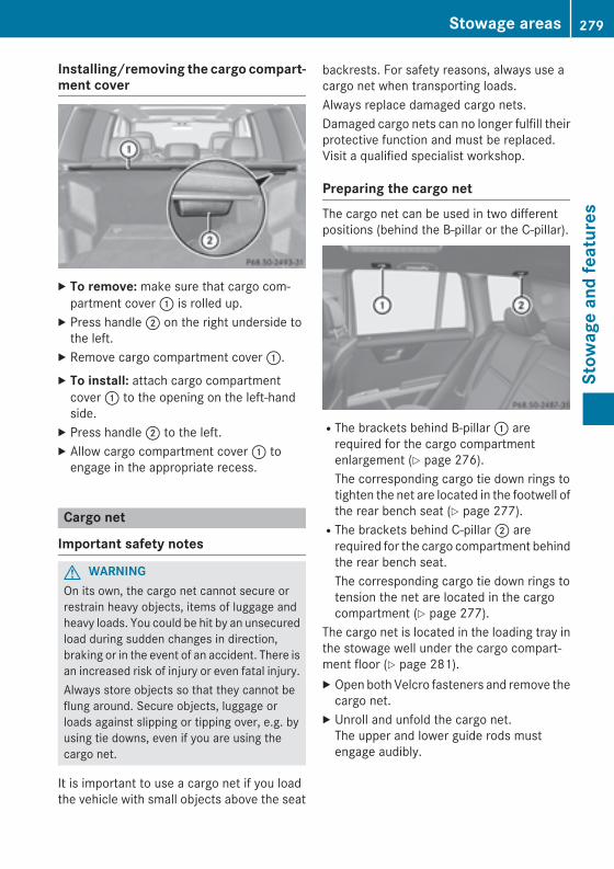
Installing/removing the cargo compart-ment cover
X To remove: make sure that cargo com-partment cover : is rolled up.
X Press handle ; on the right underside tothe left.
X Remove cargo compartment cover :.X To install: attach cargo compartment
cover : to the opening on the left-handside.
X Press handle ; to the left.X Allow cargo compartment cover : to
engage in the appropriate recess.
Cargo net
Important safety notes
G WARNINGOn its own, the cargo net cannot secure orrestrain heavy objects, items of luggage andheavy loads. You could be hit by an unsecuredload during sudden changes in direction,braking or in the event of an accident. There isan increased risk of injury or even fatal injury.Always store objects so that they cannot beflung around. Secure objects, luggage orloads against slipping or tipping over, e.g. byusing tie downs, even if you are using thecargo net.
It is important to use a cargo net if you loadthe vehicle with small objects above the seat
backrests. For safety reasons, always use acargo net when transporting loads.Always replace damaged cargo nets.Damaged cargo nets can no longer fulfill theirprotective function and must be replaced.Visit a qualified specialist workshop.
Preparing the cargo netThe cargo net can be used in two differentpositions (behind the B-pillar or the C-pillar).
RThe brackets behind B-pillar : arerequired for the cargo compartmentenlargement (Y page 276).The corresponding cargo tie down rings totighten the net are located in the footwell ofthe rear bench seat (Y page 277).RThe brackets behind C‑pillar ; are
required for the cargo compartment behindthe rear bench seat.The corresponding cargo tie down rings totension the net are located in the cargocompartment (Y page 277).
The cargo net is located in the loading tray inthe stowage well under the cargo compart-ment floor (Y page 281).X Open both Velcro fasteners and remove the
cargo net.X Unroll and unfold the cargo net.
The upper and lower guide rods mustengage audibly.
Stowage areas 279
Stow
age
and
feat
ures
Z
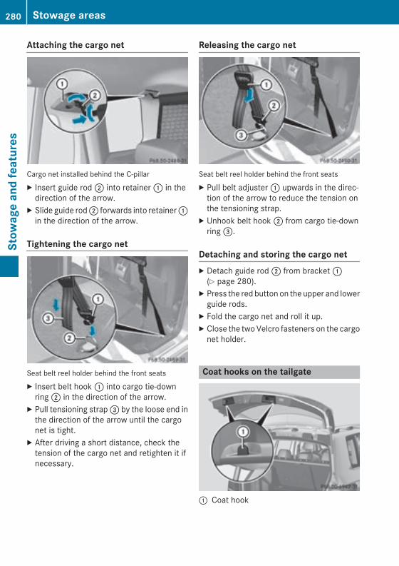
Attaching the cargo net
Cargo net installed behind the C-pillarX Insert guide rod ; into retainer : in the
direction of the arrow.X Slide guide rod ; forwards into retainer :
in the direction of the arrow.
Tightening the cargo net
Seat belt reel holder behind the front seatsX Insert belt hook : into cargo tie-down
ring ; in the direction of the arrow.X Pull tensioning strap = by the loose end in
the direction of the arrow until the cargonet is tight.
X After driving a short distance, check thetension of the cargo net and retighten it ifnecessary.
Releasing the cargo net
Seat belt reel holder behind the front seatsX Pull belt adjuster : upwards in the direc-
tion of the arrow to reduce the tension onthe tensioning strap.
X Unhook belt hook ; from cargo tie-downring =.
Detaching and storing the cargo netX Detach guide rod ; from bracket :
(Y page 280).X Press the red button on the upper and lower
guide rods.X Fold the cargo net and roll it up.X Close the two Velcro fasteners on the cargo
net holder.
Coat hooks on the tailgate
: Coat hook
280 Stowage areasSt
owag
e an
d fe
atur
es
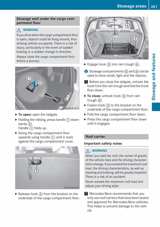
Stowage well under the cargo com-partment floor
G WARNINGIf you drive when the cargo compartment flooris open, objects could be flung around, thusstriking vehicle occupants. There is a risk ofinjury, particularly in the event of suddenbraking or a sudden change in direction.Always close the cargo compartment floorbefore a journey.
X To open: open the tailgate.X Holding the ribbing, press handle : down-
wards ;.Handle : folds up.
X Swing the cargo compartment floorupwards using handle : until it restsagainst the cargo compartment cover.
X Release hook = from the bracket on theunderside of the cargo compartment floor.
X Engage hook = into rain trough ?.
i Stowage compartments A and B can beused to stow small, light and flat objects.
! Before you close the tailgate, unhook thehook from the rain trough and fold the trunkfloor down.
X To close: unhook hook = from raintrough ?.
X Fasten hook = to the bracket on theunderside of the cargo compartment floor.
X Fold the cargo compartment floor down.X Press the cargo compartment floor down
until it engages.
Roof carrier
Important safety notes
G WARNINGWhen you load the roof, the center of gravityof the vehicle rises and the driving character-istics change. If you exceed the maximum roofload, the driving characteristics, as well assteering and braking, will be greatly impaired.There is a risk of an accident.Never exceed the maximum roof load andadjust your driving style.
! Mercedes-Benz recommends that youonly use roof carriers that have been testedand approved for Mercedes-Benz vehicles.This helps to prevent damage to the vehi-cle.
Stowage areas 281
Stow
age
and
feat
ures
Z
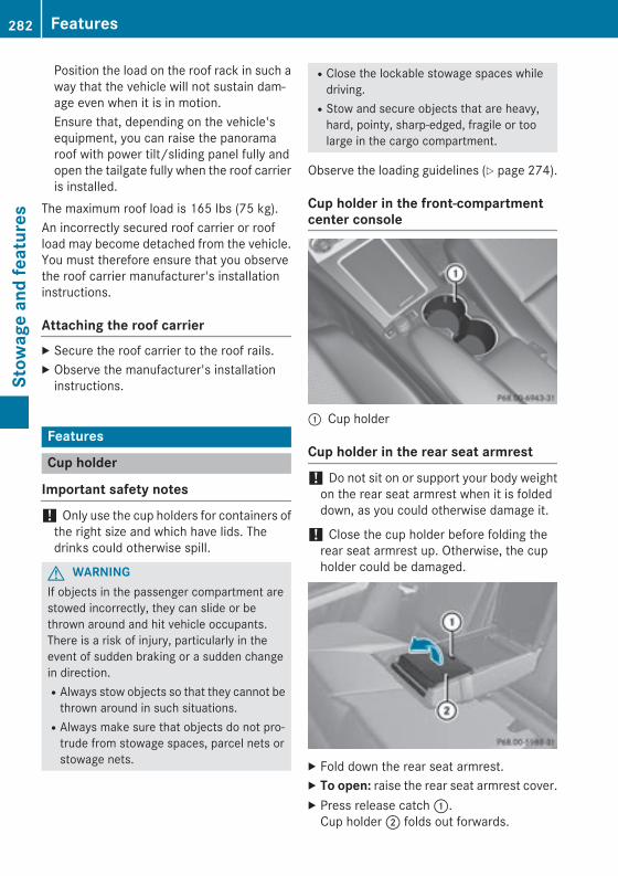
Position the load on the roof rack in such away that the vehicle will not sustain dam-age even when it is in motion.Ensure that, depending on the vehicle'sequipment, you can raise the panoramaroof with power tilt/sliding panel fully andopen the tailgate fully when the roof carrieris installed.
The maximum roof load is 165 lbs (75 kg).An incorrectly secured roof carrier or roofload may become detached from the vehicle.You must therefore ensure that you observethe roof carrier manufacturer's installationinstructions.
Attaching the roof carrierX Secure the roof carrier to the roof rails.X Observe the manufacturer's installation
instructions.
Features
Cup holder
Important safety notes
! Only use the cup holders for containers ofthe right size and which have lids. Thedrinks could otherwise spill.
G WARNINGIf objects in the passenger compartment arestowed incorrectly, they can slide or bethrown around and hit vehicle occupants.There is a risk of injury, particularly in theevent of sudden braking or a sudden changein direction.RAlways stow objects so that they cannot be
thrown around in such situations.RAlways make sure that objects do not pro-
trude from stowage spaces, parcel nets orstowage nets.
RClose the lockable stowage spaces whiledriving.RStow and secure objects that are heavy,
hard, pointy, sharp-edged, fragile or toolarge in the cargo compartment.
Observe the loading guidelines (Y page 274).
Cup holder in the front-compartmentcenter console
: Cup holder
Cup holder in the rear seat armrest
! Do not sit on or support your body weighton the rear seat armrest when it is foldeddown, as you could otherwise damage it.
! Close the cup holder before folding therear seat armrest up. Otherwise, the cupholder could be damaged.
X Fold down the rear seat armrest.X To open: raise the rear seat armrest cover.X Press release catch :.
Cup holder ; folds out forwards.
282 FeaturesSt
owag
e an
d fe
atur
es
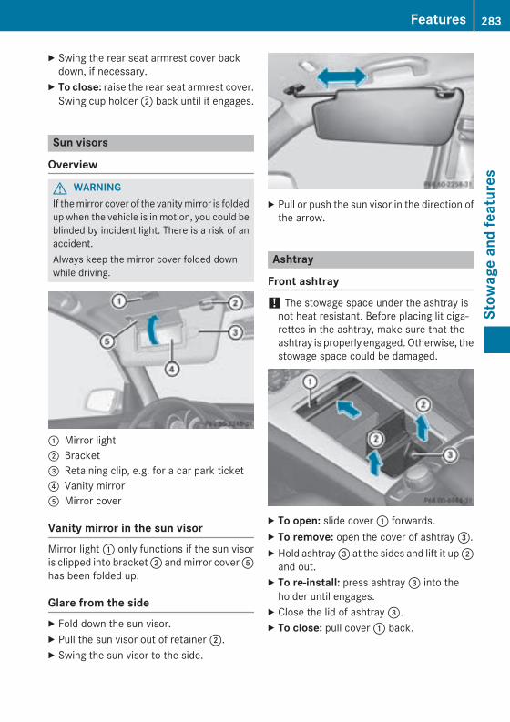
X Swing the rear seat armrest cover backdown, if necessary.
X To close: raise the rear seat armrest cover.Swing cup holder ; back until it engages.
Sun visors
Overview
G WARNINGIf the mirror cover of the vanity mirror is foldedup when the vehicle is in motion, you could beblinded by incident light. There is a risk of anaccident.Always keep the mirror cover folded downwhile driving.
: Mirror light; Bracket= Retaining clip, e.g. for a car park ticket? Vanity mirrorA Mirror cover
Vanity mirror in the sun visorMirror light : only functions if the sun visoris clipped into bracket ; and mirror cover Ahas been folded up.
Glare from the sideX Fold down the sun visor.X Pull the sun visor out of retainer ;.X Swing the sun visor to the side.
X Pull or push the sun visor in the direction ofthe arrow.
Ashtray
Front ashtray
! The stowage space under the ashtray isnot heat resistant. Before placing lit ciga-rettes in the ashtray, make sure that theashtray is properly engaged. Otherwise, thestowage space could be damaged.
X To open: slide cover : forwards.X To remove: open the cover of ashtray =.X Hold ashtray = at the sides and lift it up ;
and out.X To re-install: press ashtray = into the
holder until engages.X Close the lid of ashtray =.X To close: pull cover : back.
Features 283
Stow
age
and
feat
ures
Z
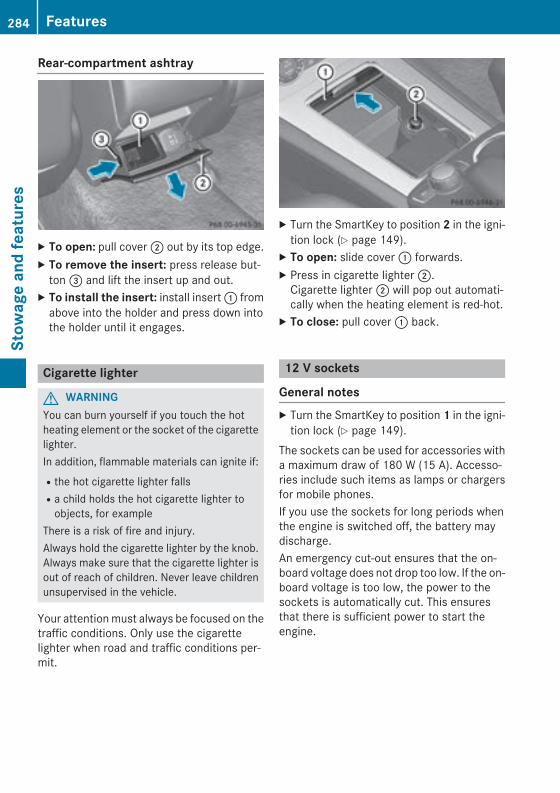
Rear-compartment ashtray
X To open: pull cover ; out by its top edge.X To remove the insert: press release but-
ton = and lift the insert up and out.X To install the insert: install insert : from
above into the holder and press down intothe holder until it engages.
Cigarette lighter
G WARNINGYou can burn yourself if you touch the hotheating element or the socket of the cigarettelighter.In addition, flammable materials can ignite if:Rthe hot cigarette lighter fallsRa child holds the hot cigarette lighter to
objects, for exampleThere is a risk of fire and injury.Always hold the cigarette lighter by the knob.Always make sure that the cigarette lighter isout of reach of children. Never leave childrenunsupervised in the vehicle.
Your attention must always be focused on thetraffic conditions. Only use the cigarettelighter when road and traffic conditions per-mit.
X Turn the SmartKey to position 2 in the igni-tion lock (Y page 149).
X To open: slide cover : forwards.X Press in cigarette lighter ;.
Cigarette lighter ; will pop out automati-cally when the heating element is red-hot.
X To close: pull cover : back.
12 V sockets
General notesX Turn the SmartKey to position 1 in the igni-
tion lock (Y page 149).The sockets can be used for accessories witha maximum draw of 180 W (15 A). Accesso-ries include such items as lamps or chargersfor mobile phones.If you use the sockets for long periods whenthe engine is switched off, the battery maydischarge.An emergency cut-out ensures that the on-board voltage does not drop too low. If the on-board voltage is too low, the power to thesockets is automatically cut. This ensuresthat there is sufficient power to start theengine.
284 FeaturesSt
owag
e an
d fe
atur
es
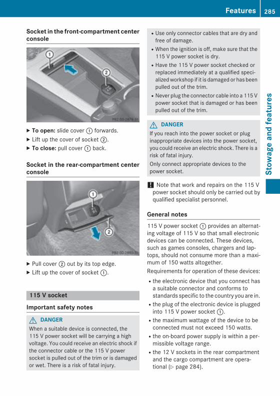
Socket in the front-compartment centerconsole
X To open: slide cover : forwards.X Lift up the cover of socket ;.X To close: pull cover : back.
Socket in the rear-compartment centerconsole
X Pull cover ; out by its top edge.X Lift up the cover of socket :.
115 V socket
Important safety notes
G DANGERWhen a suitable device is connected, the115 V power socket will be carrying a highvoltage. You could receive an electric shock ifthe connector cable or the 115 V powersocket is pulled out of the trim or is damagedor wet. There is a risk of fatal injury.
RUse only connector cables that are dry andfree of damage.RWhen the ignition is off, make sure that the
115 V power socket is dry.RHave the 115 V power socket checked or
replaced immediately at a qualified speci-alized workshop if it is damaged or has beenpulled out of the trim.RNever plug the connector cable into a 115 V
power socket that is damaged or has beenpulled out of the trim.
G DANGERIf you reach into the power socket or pluginappropriate devices into the power socket,you could receive an electric shock. There is arisk of fatal injury.Only connect appropriate devices to thepower socket.
! Note that work and repairs on the 115 Vpower socket should only be carried out byqualified specialist personnel.
General notes115 V power socket : provides an alternat-ing voltage of 115 V so that small electronicdevices can be connected. These devices,such as games consoles, chargers and lap-tops, should not consume more than a maxi-mum of 150 watts altogether.Requirements for operation of these devices:Rthe electronic device that you connect has
a suitable connector and conforms tostandards specific to the country you are in.Rthe plug of the electronic device is plugged
into 115 V power socket :.Rthe maximum wattage of the device to be
connected must not exceed 150 watts.Rthe on-board power supply is within a per-
missible voltage range.Rthe 12 V sockets in the rear compartment
and the cargo compartment are opera-tional (Y page 284).
Features 285
Stow
age
and
feat
ures
Z
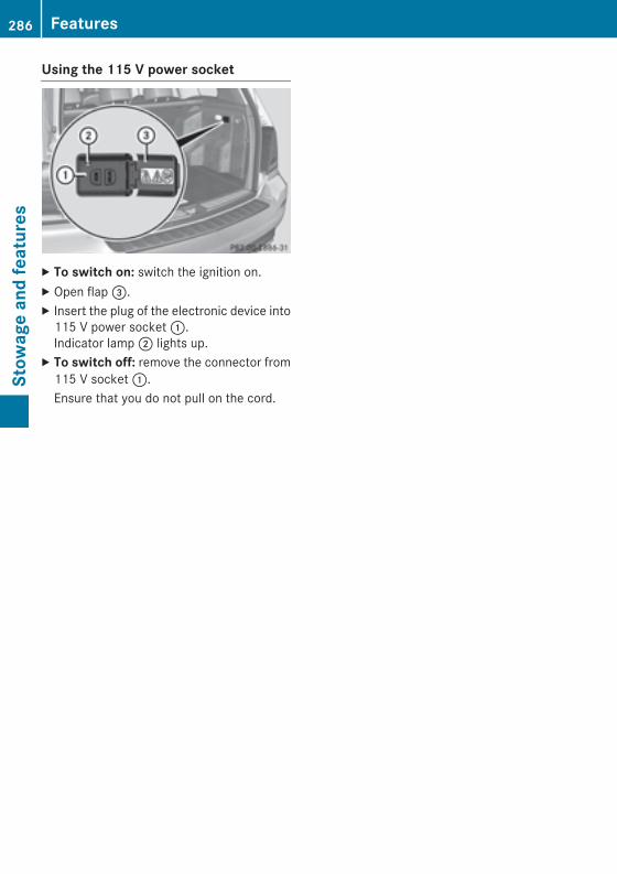
Using the 115 V power socket
X To switch on: switch the ignition on.X Open flap =.X Insert the plug of the electronic device into
115 V power socket :.Indicator lamp ; lights up.
X To switch off: remove the connector from115 V socket :.Ensure that you do not pull on the cord.
286 FeaturesSt
owag
e an
d fe
atur
es
Problems with the 115 V power socket
Problem Possible causes/consequences and M Solutions
The warning lamp onthe 115 V power socketis not lit.
The on-board voltage is too low because the battery is too weak.X Start the engine.orX Charge the battery (Y page 321).
If the indicator lamp still does not light up:X Visit a qualified specialist workshop.
The temperature of the DC/AC converter is temporarily too high.X Remove the electronic device connector from the 115 V socket.X Let the DC/AC converter cool down.
If the indicator lamp still does not light up after cooling down theconverter:X Visit a qualified specialist workshop.
You have connected a small electronic device that has a constantnominal power of less than 150 W, but a very high switch-on cur-rent. This device will not work. If you connect such a device, the115 V power socket will not supply it with power.X Connect a suitable device.
mbrace
General notesYou must have a license agreement to acti-vate the mbrace service. Make sure that yoursystem is activated and operational. To log in,press the ï MB Info call button. If any ofthe steps mentioned are not carried out, thesystem may not be activated.If you have questions about the activation,contact one of the following telephone hot-lines:RUSA: Mercedes-Benz Customer Assistance
Center at 1-800-FOR-MERCedes(1-800-367-6372) or 1-866-990-9007RCanada: Customer Service at
1-888-923-8367
Shortly after successfully registering with theservice, a user ID and password will be sent toyou by post.USA only: you can use this password to logonto the mbrace area under "Owners Online"at http://www.mbusa.com.The system is available if:Rit has been activated and is operationalRthe corresponding mobile phone network is
available for transmitting data to the Cus-tomer CenterRa service subscription is availableRthe starter battery is sufficiently charged
i Determining the location of the vehicle ona map is only possible if:RGPS reception is available.Rthe vehicle position can be forwarded to
the Customer Assistance Center.
Features 287
Stow
age
and
feat
ures
Z
The mbrace systemTo adjust the volume during a call, proceed asfollows:X Press the W or X button on the mul-
tifunction steering wheel.orX Use the volume controller of the audio sys-
tem/COMAND.The system offers various services, e.g.:RAutomatic and manual emergency callRRoadside Assistance callRMB Info callUSA only: you can find information and adescription of all available features under"Owners Online" at http://www.mbusa.com.
System self-testAfter you have switched on the ignition, thesystem carries out a self-diagnosis.A malfunction in the system has been detec-ted if one of the following occurs:RThe indicator lamp in the SOS button does
not come on during the system self-test.RThe indicator lamp in the F Roadside
Assistance button does not light up duringself-diagnosis of the system.RThe indicator lamp in the ï MB Info call
button does not light up during self-diag-nosis of the system.RThe indicator lamp in one or more of the
following buttons continues to light up redafter the system self-diagnosis:- SOS button- F Roadside Assistance call button- ï MB Info call buttonRAfter the system self-diagnosis, the Inop‐erative or Service Not Activatedmessage appears in the multifunction dis-play.
If a malfunction is indicated as outlinedabove, the system may not operate as expec-ted. In the event of an emergency, help willhave to be summoned by other means.
Have the system checked at the nearestauthorized Mercedes-Benz Center or contactthe following service hotlines:RUSA: Mercedes-Benz Customer Assistance
Center at 1-800-FOR-MERCedes(1-800-367-6372) or 1-866-990-9007RCanada: Customer Service at
1-888-923-8367
Emergency call
Important safety notesG WARNINGIt can be dangerous to remain in the vehicle,even if you have pressed the SOS button in anemergency if:Ryou see smoke inside or outside of the vehi-
cle, e.g. if there is a fire after an accidentRthe vehicle is on a dangerous section of
roadRthe vehicle is not visible or cannot easily be
seen by other road users, particularly whendark or in poor visibility conditions
There is a risk of an accident and injury.Leave the vehicle immediately in this or simi-lar situations as soon as it is safe to do so.Move to a safe location along with other vehi-cle occupants. In such situations, secure thevehicle in accordance with national regula-tions, e. g. with a warning triangle.
You must have a license agreement to acti-vate the mbrace service. Make sure that yoursystem is activated and operational. To reg-ister, press the ï MB Info call button. Ifany of the steps mentioned are not carriedout, the system may not be activated.If you have questions about the activation,contact one of the following telephone hot-lines:RUSA: Mercedes-Benz Customer Assistance
Center at 1-800-FOR-MERCedes(1-800-367-6372) or 1-866-990-9007RCanada: Customer Service at
1-888-923-8367
288 FeaturesSt
owag
e an
d fe
atur
es

General notesAn emergency call is dialed automatically if anair bag or Emergency Tensioning Device istriggered.
i You cannot end an automatically trig-gered emergency call yourself.
An emergency call can also be initiated man-ually.As soon as the emergency call has been ini-tiated, the indicator lamp in the SOS buttonflashes. The multifunction display shows theConnecting Call message.The audio output is muted.Once the connection has been made, theCall Connected message appears in themultifunction display.All important information on the emergency istransmitted, for example:Rcurrent location of the vehicle (as deter-
mined by the GPS system)Rvehicle identification numberRinformation on the severity of the accidentShortly after the emergency call has been ini-tiated, a voice connection is automaticallyestablished between the Customer Assis-tance Center and the vehicle occupants.RIf the vehicle occupants respond, the
Mercedes-Benz Customer Assistance Cen-ter attempts to get more information on theemergency.RIf there is no response from the vehicle
occupants, an ambulance is immediatelysent to the vehicle.
If no voice connection can be established tothe Mercedes-Benz Customer AssistanceCenter, the system has been unable to initiatean emergency call.This can occur, for example, if the relevantmobile phone network is not available. Theindicator lamp in the SOS button flashes con-tinuously.The Call Failed message appears in themultifunction display and must be confirmed.
In this case, summon assistance by othermeans.
Making an emergency call
X To initiate an emergency call manually:press cover : briefly to open.
X Press SOS button ; briefly.The indicator lamp in SOS button ;flashes until the emergency call is conclu-ded.
X Wait for a voice connection to theMercedes-Benz Customer Assistance Cen-ter.
X After the emergency call, close cover :.
i If the mobile phone network is unavaila-ble, mbrace will not be able to make theemergency call. If you leave the vehicleimmediately after pressing the SOS button,you will not know whether mbrace placedthe emergency call. In this case, alwayssummon assistance by other means.
Roadside Assistance button
Features 289
Stow
age
and
feat
ures
Z
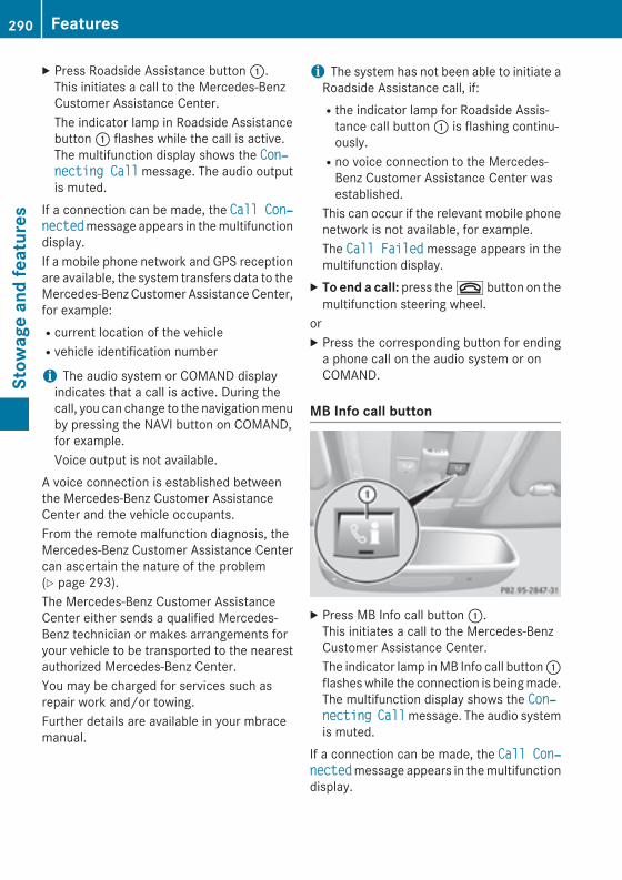
X Press Roadside Assistance button :.This initiates a call to the Mercedes-BenzCustomer Assistance Center.The indicator lamp in Roadside Assistancebutton : flashes while the call is active.The multifunction display shows the Con‐necting Call message. The audio outputis muted.
If a connection can be made, the Call Con‐nected message appears in the multifunctiondisplay.If a mobile phone network and GPS receptionare available, the system transfers data to theMercedes-Benz Customer Assistance Center,for example:Rcurrent location of the vehicleRvehicle identification number
i The audio system or COMAND displayindicates that a call is active. During thecall, you can change to the navigation menuby pressing the NAVI button on COMAND,for example.Voice output is not available.
A voice connection is established betweenthe Mercedes-Benz Customer AssistanceCenter and the vehicle occupants.From the remote malfunction diagnosis, theMercedes-Benz Customer Assistance Centercan ascertain the nature of the problem(Y page 293).The Mercedes-Benz Customer AssistanceCenter either sends a qualified Mercedes-Benz technician or makes arrangements foryour vehicle to be transported to the nearestauthorized Mercedes-Benz Center.You may be charged for services such asrepair work and/or towing.Further details are available in your mbracemanual.
i The system has not been able to initiate aRoadside Assistance call, if:Rthe indicator lamp for Roadside Assis-
tance call button : is flashing continu-ously.Rno voice connection to the Mercedes-
Benz Customer Assistance Center wasestablished.
This can occur if the relevant mobile phonenetwork is not available, for example.The Call Failed message appears in themultifunction display.
X To end a call: press the ~ button on themultifunction steering wheel.
orX Press the corresponding button for ending
a phone call on the audio system or onCOMAND.
MB Info call button
X Press MB Info call button :.This initiates a call to the Mercedes-BenzCustomer Assistance Center.The indicator lamp in MB Info call button :flashes while the connection is being made.The multifunction display shows the Con‐necting Call message. The audio systemis muted.
If a connection can be made, the Call Con‐nected message appears in the multifunctiondisplay.
290 FeaturesSt
owag
e an
d fe
atur
es
If a mobile phone network and GPS receptionare available, the system transfers data to theMercedes-Benz Customer Assistance Center,for example:Rcurrent location of the vehicleRvehicle identification number
i The audio system or COMAND displayindicates that a call is active. During thecall, you can change to the navigation menuby pressing the NAVI button on COMAND,for example.Voice output is not available.
A voice connection is established betweenthe Mercedes-Benz Customer AssistanceCenter and the vehicle occupants.You receive information about operating yourvehicle, about the nearest authorizedMercedes-Benz Center and about other prod-ucts and services from Mercedes-Benz.USA only: you can find further information onthe mbrace system under "Owners Online" athttp://www.mbusa.com.
i The system has not been able to initiatean MB Info call, if:Rthe indicator lamp in MB Info call but-
ton : is flashing continuously.Rno voice connection to the Mercedes-
Benz Customer Assistance Center wasestablished.
This can occur if the relevant mobile phonenetwork is not available, for example.The Call Failed message appears in themultifunction display.
X To end a call: press the ~ button on themultifunction steering wheel.
orX Press the corresponding button for ending
a phone call on the audio system or onCOMAND.
Call priorityWhen service calls are active, e.g. RoadsideAssistance or MB Info calls, an emergencycall can still be initiated. In this case, an emer-gency call will take priority and override allother active calls.The indicator lamp of the respective buttonflashes until the call is ended.An emergency call can only be terminated bythe Mercedes-Benz Customer AssistanceCenter.All other calls can be ended by pressing:Rthe ~ button on the multifunction steer-
ing wheelRthe corresponding button on the audio sys-
tem or on COMAND for ending a telephonecall
i When a call is initiated, the audio systemis muted. The mobile phone is no longerconnected to COMAND. However, if youwant to use your mobile phone, do so onlywhen the vehicle is stationary and in a safelocation.
Downloading destinations in COMAND
Downloading destinationsDownloading destinations gives you accessto a database with over 15 million points ofinterest (POIs). These can be downloaded onthe navigation system in your vehicle. If youknow the destination, the address can bedownloaded. Alternatively, you can obtain thelocation of Points of Interest (POIs)/impor-tant destinations in the vicinity.Furthermore, you can download routes withup to 20 way points.You are prompted to confirm route guidanceto the address entered.The system calculates the route and subse-quently starts the route guidance with theaddress entered.
i If you select No, the address can be savedin the address book.
Features 291
Stow
age
and
feat
ures
Z
i The destination download function isavailable if the relevant mobile phone net-work is available and data transfer is pos-sible.
i The destination download function canonly be used if the vehicle is equipped witha navigation system.
Route AssistanceThis service is part of the mbrace PLUS Pack-age and cannot be purchased separately.
i You can also use the Route Assistancefunction if your vehicle is not equipped witha navigation system.
Within the framework of this service, youreceive a professional and reliable form ofnavigation support without having to leaveyour vehicle.The customer service representative finds asuitable route depending on your vehicle'scurrent position and the desired destination.You will then be guided live through the cur-rent route section.
Search & Send"Search & Send" is a destination entry ser-vice. You can find further information on"Search & Send" in the separate COMANDoperating instructions.
Vehicle remote openingYou can use the vehicle remote opening if youhave unintentionally locked your vehicle anda replacement SmartKey is not available.The vehicle can be opened by the Mercedes-Benz Customer Assistance Center.The vehicle can be immediately openedremotely within four days of the ignition beingturned off. After this time, the remote unlock-ing may be delayed by 15 to 60 minutes. After30 days, the vehicle can no longer be openedremotely.X Contact the following service hotlines:
RUSA: Mercedes-Benz Customer Assis-tance Center at 1-800-FOR-MERCedes(1-800-367-6372) or 1-866-990-9007RCanada: Customer Service at
1-888-923-8367You will be asked for your password.
X Return to your vehicle at the time agreedupon with the Mercedes-Benz CustomerAssistance Center.
USA only: alternatively, the vehicle can beopened via:Rthe Internet, under the "Owners Online"
sectionRthe telephone application (e. g. for iPhone®,
Android)To do this, you will need your identificationnumber and password.
i Vehicle remote opening is only possible ifthe corresponding mobile phone network isaccessible.
Vehicle remote closingThe valet locking feature can be used whenyou have forgotten to lock the vehicle and youare no longer nearby.The vehicle can then be locked by theMercedes-Benz Customer Assistance Center.The vehicle can be immediately remotelylocked within four days of the ignition beingturned off. After this time, remote closing maybe delayed by 15 to 60 minutes. After 30 daysthe vehicle can no longer be locked remotely.X Contact the following service hotlines:RUSA: Mercedes-Benz Customer Assis-
tance Center at 1-800-FOR-MERCedes(1-800-367-6372) or 1-866-990-9007RCanada: Customer Service at
1-888-923-8367You will be asked for your password.
The next time you are inside the vehicle andyou switch on the ignition, the Doors Locked Remotely message appears in themultifunction display.
292 FeaturesSt
owag
e an
d fe
atur
es
USA only: alternatively, the vehicle can belocked via:Rthe Internet, under the "Owners Online"
sectionRthe telephone application (e. g. for iPhone®,
Android)To do this, you will need your identificationnumber and password.
i The vehicle remote closing feature isavailable when the relevant mobile phonenetwork is available and data connection ispossible.
Stolen vehicle recovery serviceIf your vehicle has been stolen:X Notify the police.
The police will issue a numbered incidentreport.
X This number will be forwarded to theMercedes-Benz Customer Assistance Cen-ter together with your PIN.The Mercedes-Benz Customer AssistanceCenter then tries to locate the system. TheMercedes-Benz Customer Assistance Cen-ter contacts you and the local law enforce-ment agency if the vehicle is located.However, only the law enforcement agencyis informed of the location of the vehicle.
i If the anti-theft alarm system is activatedfor longer than 30 seconds, the Mercedes-Benz Customer Assistance Center is auto-matically notified.
Vehicle Health CheckWith the Vehicle Health Check, the CustomerAssistance Center can provide improved sup-port for problems with your vehicle. During anexisting call, vehicle data is transferred to theCustomer Assistance Center. The customerservice representative can use the receiveddata to decide what kind of assistance isrequired. You are then, for example, guided tothe nearest authorized Mercedes-Benz Cen-ter or a recovery vehicle is called.
If vehicle data needs to be transferred duringan MB Info call or a Roadside Assistance call,this is initiated by the Customer AssistanceCenter. You will see the Roadside Assis‐tance Connected message in the COMANDdisplay. If the vehicle remote malfunctiondiagnosis can be started, the Request for vehicle diagnosis received. Start vehicle diagnosis? message appears inthe display.X Confirm the message with Yes.X When the Vehicle Diagnosis Please start ignition message appears, turnthe SmartKey to position 2 in the ignitionlock (Y page 149).
X When the Please follow the instruc‐tions received by phone and move your vehicle to a safe positionmessage appears, follow the customer ser-vice representative's instructions.The message in the display disappears.If you select Cancel the remote malfunc-tion diagnosis is canceled completely.The vehicle operating state check begins.You will see the Vehicle diagnosis activated message.
When the diagnosis is completed, the Trans‐fer vehicle diagnostics data (Voice connection may be interrupted dur‐ing data transfer) message appears. Thevehicle data can now be sent to the CustomerAssistance center.X Press OK to confirm the message.
The voice connection with the CustomerAssistance Center is terminated.You will see the Vehicle diagnosis: Transferring data... message.The vehicle data is sent to the CustomerAssistance Center.
Depending on what the customer service rep-resentative agreed with you, the voice con-nection is re-established after the transfer iscomplete. If necessary, you will be contactedat a later time by another means, e.g. by e-mail or phone.
Features 293
Stow
age
and
feat
ures
Z
Another function of the Vehicle Health Checkis the transfer of service data to the CustomerAssistance Center. If a service is overdue, theCOMAND display shows a message aboutvarious special offers at your workshop.USA only: this information can also be calledup under "Owners Online" at http://www.mbusa.com.Information on the data stored in the vehicle(Y page 28).Information on Roadside Assistance(Y page 24).
Downloading routesDownloading routes allows you to transferand save predefined routes in the navigationsystem. To do this, an SD memory card mustbe inserted into the COMAND system. If noSD memory card is inserted, you must insertthe card into the card slot on the COMANDsystem before saving.A route can be prepared and sent either by acustomer service representative or via thembrace portal on the Internet.Each route can include up to 20 way points.Once a route has been received by the navi-gation system, you will see the <route name> has been saved to memory card. Do you want to start route guidance?message in the COMAND display. The route issaved to the SD memory card.X To start route guidance: select Yes.
An overview of the route is shown in thedisplay.
i If you select No, the saved route can becalled up later via the navigation menu.
X Select Start.Route guidance is started.
i Downloaded and saved data can be calledup again in COMAND.You can find further information in the sep-arate COMAND Operating Instructions.
Speed alertYou can define the upper speed limit, whichmust not be exceeded by the vehicle.If this selected speed is exceeded by the vehi-cle, a message will be sent to the CustomerAssistance Center. The Customer AssistanceCenter then forwards this information to you.You can select the way in which you receivethis information beforehand. Possible optionsinclude text message, e-mail or an automatedcall.The data you receive contains the followinginformation:Rthe location where the speed limit was
exceededRthe time at which the speed limit was
exceededRthe selected speed limit which was excee-
ded
Geo fencingGeo fencing allows you to select areas whichthe vehicle should not enter or leave. You willbe informed if the vehicle crosses the boun-daries of the selected areas. You can selectthe way in which you receive this informationbeforehand. Possible options include textmessage, e-mail or an automated call.The area can be determined as either a circleor a polygon with a maximum of ten corners.You can specify up to ten areas simultane-ously. Different settings are possible for eacharea.USA only: these settings can be called upunder "Owners Online" at http://www.mbusa.com.Alternatively, you can trigger an MB Info calland inform the customer service representa-tive that you wish to activate geo fencing.Currently inactive areas can be activated bytext message.
294 FeaturesSt
owag
e an
d fe
atur
es
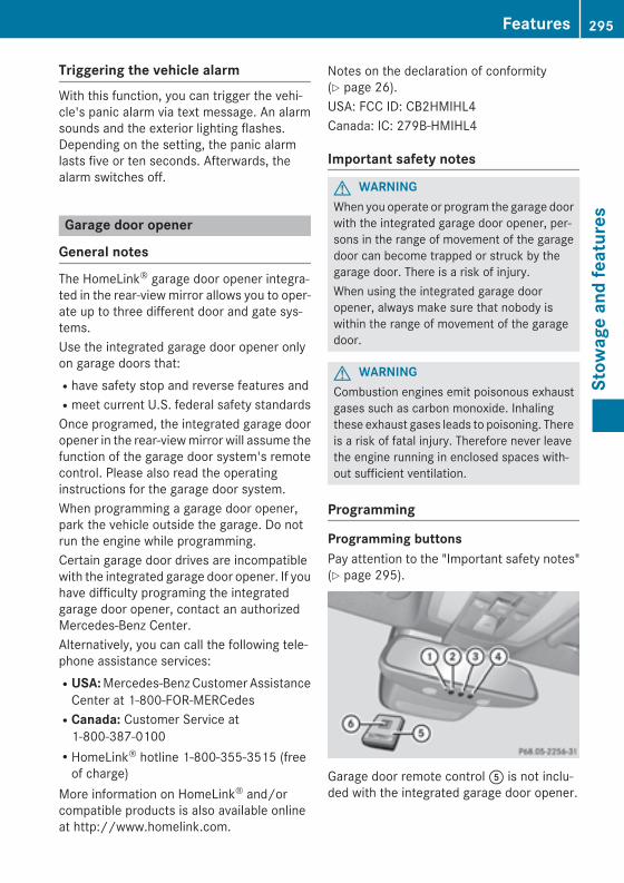
Triggering the vehicle alarmWith this function, you can trigger the vehi-cle's panic alarm via text message. An alarmsounds and the exterior lighting flashes.Depending on the setting, the panic alarmlasts five or ten seconds. Afterwards, thealarm switches off.
Garage door opener
General notes
The HomeLink® garage door opener integra-ted in the rear-view mirror allows you to oper-ate up to three different door and gate sys-tems.Use the integrated garage door opener onlyon garage doors that:Rhave safety stop and reverse features andRmeet current U.S. federal safety standardsOnce programed, the integrated garage dooropener in the rear-view mirror will assume thefunction of the garage door system's remotecontrol. Please also read the operatinginstructions for the garage door system.When programming a garage door opener,park the vehicle outside the garage. Do notrun the engine while programming.Certain garage door drives are incompatiblewith the integrated garage door opener. If youhave difficulty programing the integratedgarage door opener, contact an authorizedMercedes-Benz Center.Alternatively, you can call the following tele-phone assistance services:RUSA: Mercedes-Benz Customer Assistance
Center at 1-800-FOR-MERCedesRCanada: Customer Service at
1-800-387-0100RHomeLink® hotline 1-800-355-3515 (free
of charge)More information on HomeLink® and/orcompatible products is also available onlineat http://www.homelink.com.
Notes on the declaration of conformity(Y page 26).USA: FCC ID: CB2HMIHL4Canada: IC: 279B-HMIHL4
Important safety notes
G WARNINGWhen you operate or program the garage doorwith the integrated garage door opener, per-sons in the range of movement of the garagedoor can become trapped or struck by thegarage door. There is a risk of injury.When using the integrated garage dooropener, always make sure that nobody iswithin the range of movement of the garagedoor.
G WARNINGCombustion engines emit poisonous exhaustgases such as carbon monoxide. Inhalingthese exhaust gases leads to poisoning. Thereis a risk of fatal injury. Therefore never leavethe engine running in enclosed spaces with-out sufficient ventilation.
Programming
Programming buttonsPay attention to the "Important safety notes"(Y page 295).
Garage door remote control A is not inclu-ded with the integrated garage door opener.
Features 295
Stow
age
and
feat
ures
Z
X Turn the SmartKey to position 2 in the igni-tion lock (Y page 149).
X Select one of buttons ; to ? to use tocontrol the garage door drive.
X To start programming mode: press andhold one of buttons ; to ? on the inte-grated garage door opener.The garage door opener is now in program-ming mode. After a short time, indicatorlamp : lights up yellow.Indicator lamp : lights up yellow as soonas button ;, = or ? is programmed forthe first time. If the selected button hasalready been programmed, indicatorlamp : will only light up yellow after tenseconds have elapsed.
X Release button ;, = or ?. Indicatorlamp : flashes yellow.
X To program the remote control: pointgarage door remote control A towardsbuttons ; to ? on the rear-view mirror ata distance of 2 to 8 inches (5 to 20 cm).
X Press and hold button B on remote controlA until indicator lamp : lights up green.When indicator lamp : lights up green:programming is finished.When indicator lamp : flashes green: pro-gramming was successful. The next step isto synchronize the rolling code(Y page 296).
X Release button B on remote control A forthe garage door drive system.If indicator lamp : lights up red: repeat theprograming procedure for the correspond-ing button on the rear-view mirror. Whendoing so, vary the distance between remotecontrol A and the rear-view mirror.The required distance between remotecontrol A and the integrated garage dooropener depends on the garage door drivesystem. Several attempts might be neces-sary. You should test every position for atleast 25 seconds before trying anotherposition.
Synchronizing the rolling codePay attention to the "Important safety notes"(Y page 295).If the garage door system uses a rolling code,you will also have to synchronize the garagedoor system with the integrated garage dooropener in the rear-view mirror. To do this youwill need to use the programming button onthe door drive control panel. The program-ming button may be positioned at differentlocations depending on the manufacturer. Itis usually located on the door drive unit on thegarage ceiling.Familiarize yourself with the garage doordrive operating instructions, e.g. under "Pro-gramming of additional remote controls",before carrying out the following steps.Your vehicle must be within reach of thegarage door or gate opener drive. Make surethat neither your vehicle nor any persons/objects are present within the sweep of thedoor or gate.X Turn the SmartKey to position 2 in the igni-
tion lock (Y page 149).X Get out of the vehicle.X Press the programming button on the door
drive unit.Usually, you now have 30 seconds to ini-tiate the next step.
X Get into the vehicle.X Press previously programmed button ;,= or ? on the integrated garage dooropener until the door closes.The rolling code synchronization is thencomplete.
Notes on programming the remote con-trolCanadian radio frequency laws require a"break" (or interruption) of the transmissionsignals after broadcasting for a few seconds.Therefore, these signals may not last longenough for the integrated garage dooropener. The signal is not recognized duringprogramming. Comparable with Canadian
296 FeaturesSt
owag
e an
d fe
atur
es
law, some U.S. garage door openers also fea-ture a "break".Proceed as follows:Rif you live in CanadaRif you have difficulties programming the
garage door opener (regardless of whereyou live) when using the programmingsteps
X Press and hold one of buttons ; to ? onthe integrated garage door opener.After a short time, indicator lamp : lightsup yellow.
X Release the button.Indicator lamp : flashes yellow.
X Press button B of garage door remotecontrol A for two seconds, then release itfor two seconds.
X Press button B again for two seconds.X Repeat this sequence on button B of
remote control A until indicator lamp :lights up green.When indicator lamp : lights up green:programming is finished.When indicator lamp : flashes green: pro-gramming was successful. The next step isto synchronize the rolling code.
X Release button B of remote control A ofthe garage door drive.If indicator lamp : lights up red: repeat theprogramming process for the correspond-ing button on the rear-view mirror. Whendoing so, vary the distance between remotecontrol A and the rear-view mirror.The required distance between remotecontrol A and the integrated garage dooropener depends on the garage door drivesystem. Several attempts might be neces-sary. You should test every position for atleast 25 seconds before trying anotherposition.
Problems when programmingIf you are experiencing problems programingthe integrated garage door opener on therear-view mirror, take note of the followinginstructions:RCheck the transmitter frequency used by
garage door drive remote control A andwhether it is supported. The transmitterfrequency can usually be found on the backof the garage door drive remote control.The integrated garage door opener is com-patible with devices that have units whichoperate in the frequency range of 280 to433 MHz.RReplace the batteries in garage door
remote control A. This increases the like-lihood that garage door remote control Awill transmit a strong and precise signal tothe integrated garage door opener.RWhen programming, hold remote controlA at varying distances and angles from thebutton which you are programming. Try var-ious angles at a distance between 2and12 inches (5to 30 cm) or at the same anglebut at varying distances.RIf another remote control is available for the
same garage door drive, repeat the sameprogramming steps with this remote con-trol. Before performing these steps, makesure that new batteries have been installedin garage door drive remote control A.RNote that some remote controls only trans-
mit for a limited amount of time (the indi-cator lamp on the remote control goes out).Press button B on remote control A againbefore transmission ends.RAlign the antenna cable of the garage door
opener unit. This can improve signal recep-tion/transmission.
Opening/closing the garage doorAfter it has been programmed, the integratedgarage door opener performs the function ofthe garage door system remote control.
Features 297
Stow
age
and
feat
ures
Z
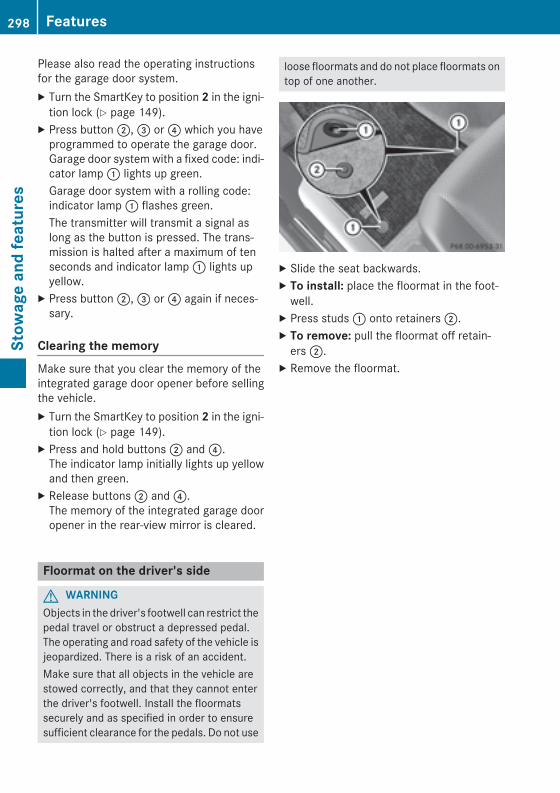
Please also read the operating instructionsfor the garage door system.X Turn the SmartKey to position 2 in the igni-
tion lock (Y page 149).X Press button ;, = or ? which you have
programmed to operate the garage door.Garage door system with a fixed code: indi-cator lamp : lights up green.Garage door system with a rolling code:indicator lamp : flashes green.The transmitter will transmit a signal aslong as the button is pressed. The trans-mission is halted after a maximum of tenseconds and indicator lamp : lights upyellow.
X Press button ;, = or ? again if neces-sary.
Clearing the memoryMake sure that you clear the memory of theintegrated garage door opener before sellingthe vehicle.X Turn the SmartKey to position 2 in the igni-
tion lock (Y page 149).X Press and hold buttons ; and ?.
The indicator lamp initially lights up yellowand then green.
X Release buttons ; and ?.The memory of the integrated garage dooropener in the rear-view mirror is cleared.
Floormat on the driver's side
G WARNINGObjects in the driver's footwell can restrict thepedal travel or obstruct a depressed pedal.The operating and road safety of the vehicle isjeopardized. There is a risk of an accident.Make sure that all objects in the vehicle arestowed correctly, and that they cannot enterthe driver's footwell. Install the floormatssecurely and as specified in order to ensuresufficient clearance for the pedals. Do not use
loose floormats and do not place floormats ontop of one another.
X Slide the seat backwards.X To install: place the floormat in the foot-
well.X Press studs : onto retainers ;.X To remove: pull the floormat off retain-
ers ;.X Remove the floormat.
298 FeaturesSt
owag
e an
d fe
atur
es

Useful information ............................ 300Engine compartment ........................ 300ASSYST PLUS .................................... 304Care .................................................... 305
299
Mai
nten
ance
and
car
e
Useful information
i This Operator's Manual describes allmodels and all standard and optional equip-ment of your vehicle available at the time ofpublication of the Operator's Manual.Country-specific differences are possible.Please note that your vehicle may not beequipped with all features described. Thisalso applies to safety-related systems andfunctions.
i Read the information on qualified special-ist workshops (Y page 27).
Engine compartment
Hood
Important safety notes
G WARNINGIf the hood is unlatched, it may open up whenthe vehicle is in motion and block your view.There is a risk of an accident.Never unlatch the hood while driving. Beforeevery trip, ensure that the hood is locked.
G WARNINGWhen opening and closing the hood, it maysuddenly fall into the closed position. There isa risk of injury to persons within range ofmovement of the hood.Open and close the hood only when no one iswithin its range of movement.
G WARNINGOpening the hood when the engine is over-heated or when there is a fire in the enginecompartment could expose you to hot gasesor other service products. There is a risk ofinjury.Let an overheated engine cool down beforeopening the hood. If there is a fire in theengine compartment, keep the hood closedand contact the fire department.
G WARNINGThe engine compartment contains movingcomponents. Certain components, such asthe radiator fan, may continue to run or startagain suddenly when the ignition is off. Thereis a risk of injury.If you need to do any work inside the enginecompartment:Rswitch off the ignitionRnever reach into the area where there is a
risk of danger from moving components,such as the fan rotation areaRremove jewelry and watchesRkeep items of clothing and hair, for exam-
ple, away from moving parts
G WARNINGThe ignition system and the fuel injection sys-tem work under high voltage. If you touchcomponents which are under voltage, youcould get an electric shock. There is a risk ofinjury.Never touch components of the ignition sys-tem or fuel injection system when the ignitionis switched on.
Opening the hood
G WARNINGCertain components in the engine compart-ment, such as the engine, radiator and partsof the exhaust system, can become very hot.Working in the engine compartment poses arisk of injury.Where possible, let the engine cool down andtouch only the components described in thefollowing.
G WARNINGWhen the hood is open and the windshieldwipers are set in motion, you can be injured bythe wiper linkage. There is a risk of injury.Always switch off the windshield wipers andthe ignition before opening the hood.
300 Engine compartmentM
aint
enan
ce a
nd c
are

! Make sure that the windshield wipers arenot folded away from the windshield. Youcould otherwise damage the windshieldwipers or the hood.
X Make sure that the windshield wipers areturned off.
X Pull release lever : on the hood.The hood is released.
X Reach into the gap, pull hood catch han-dle ; up and lift the hood.If you lift the hood by approximately 15 in(40 cm), the hood is opened and held openautomatically by the gas-filled strut.
Closing the hoodX Lower the hood and let it fall from a height
of approximately 8 in (20 cm).X Check that the hood has engaged properly.
If the hood can be raised slightly, it is notproperly engaged. Open it again and closeit with a little more force.
Engine oil
General notes on the oil levelDepending on your driving style, the vehicleconsumes up to 0.9 US qt (0.8 liters) of oil per600 miles (1,000 km). The oil consumptionmay be higher than this when the vehicle isnew or if you frequently drive at high enginespeeds.Depending on the engine, the oil dipstick maybe in a different location.When checking the oil level:Rpark the vehicle on a level surface.Rthe engine should be switched off for
approximately five minutes if the engine isat normal operating temperature.Rif the engine is not at normal operating
temperature, e.g. if the engine was onlystarted briefly, wait about 30 minutesbefore carrying out the measurement.
Checking the oil level using the oil dip-stick
G WARNINGCertain components in the engine compart-ment, such as the engine, radiator and partsof the exhaust system, can become very hot.Working in the engine compartment poses arisk of injury.Where possible, let the engine cool down andtouch only the components described in thefollowing.
Example: vehicles with a gasoline engine
Engine compartment 301
Mai
nten
ance
and
car
e
Z
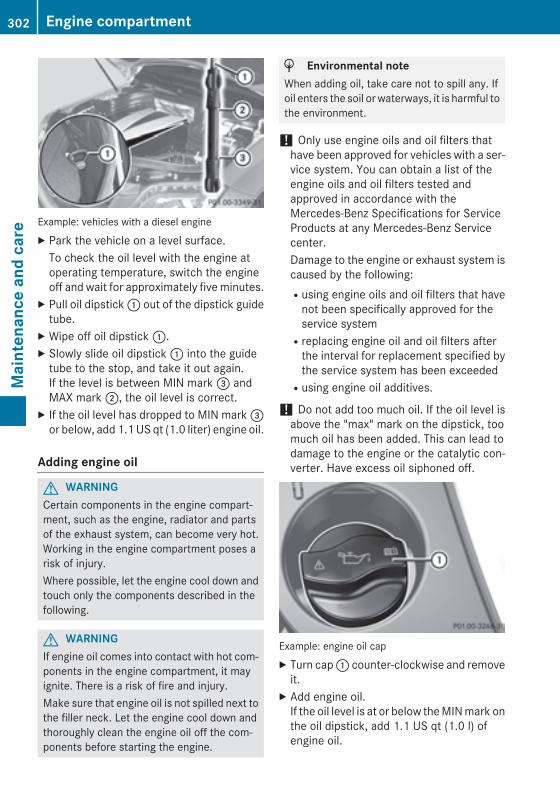
Example: vehicles with a diesel engineX Park the vehicle on a level surface.
To check the oil level with the engine atoperating temperature, switch the engineoff and wait for approximately five minutes.
X Pull oil dipstick : out of the dipstick guidetube.
X Wipe off oil dipstick :.X Slowly slide oil dipstick : into the guide
tube to the stop, and take it out again.If the level is between MIN mark = andMAX mark ;, the oil level is correct.
X If the oil level has dropped to MIN mark =or below, add 1.1 US qt (1.0 liter) engine oil.
Adding engine oil
G WARNINGCertain components in the engine compart-ment, such as the engine, radiator and partsof the exhaust system, can become very hot.Working in the engine compartment poses arisk of injury.Where possible, let the engine cool down andtouch only the components described in thefollowing.
G WARNINGIf engine oil comes into contact with hot com-ponents in the engine compartment, it mayignite. There is a risk of fire and injury.Make sure that engine oil is not spilled next tothe filler neck. Let the engine cool down andthoroughly clean the engine oil off the com-ponents before starting the engine.
H Environmental noteWhen adding oil, take care not to spill any. Ifoil enters the soil or waterways, it is harmful tothe environment.
! Only use engine oils and oil filters thathave been approved for vehicles with a ser-vice system. You can obtain a list of theengine oils and oil filters tested andapproved in accordance with theMercedes-Benz Specifications for ServiceProducts at any Mercedes-Benz Servicecenter.Damage to the engine or exhaust system iscaused by the following:Rusing engine oils and oil filters that have
not been specifically approved for theservice systemRreplacing engine oil and oil filters after
the interval for replacement specified bythe service system has been exceededRusing engine oil additives.
! Do not add too much oil. If the oil level isabove the "max" mark on the dipstick, toomuch oil has been added. This can lead todamage to the engine or the catalytic con-verter. Have excess oil siphoned off.
Example: engine oil capX Turn cap : counter-clockwise and remove
it.X Add engine oil.
If the oil level is at or below the MIN mark onthe oil dipstick, add 1.1 US qt (1.0 l) ofengine oil.
302 Engine compartmentM
aint
enan
ce a
nd c
are
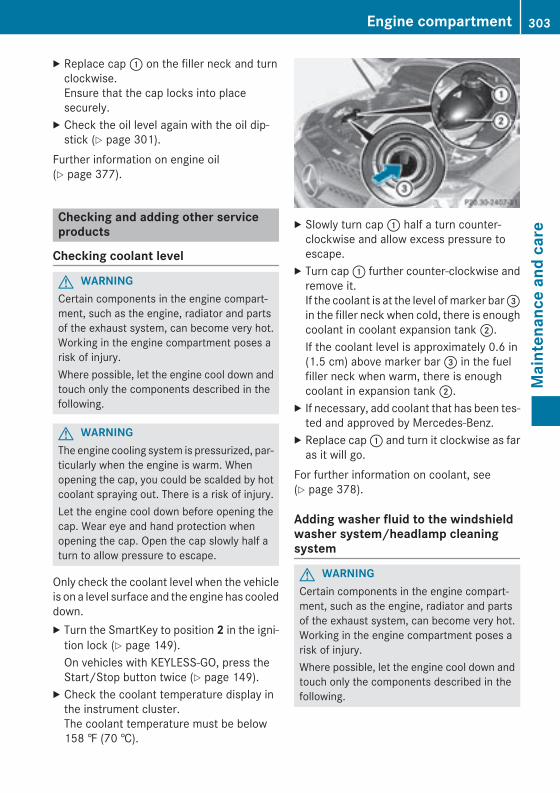
X Replace cap : on the filler neck and turnclockwise.Ensure that the cap locks into placesecurely.
X Check the oil level again with the oil dip-stick (Y page 301).
Further information on engine oil(Y page 377).
Checking and adding other serviceproducts
Checking coolant level
G WARNINGCertain components in the engine compart-ment, such as the engine, radiator and partsof the exhaust system, can become very hot.Working in the engine compartment poses arisk of injury.Where possible, let the engine cool down andtouch only the components described in thefollowing.
G WARNINGThe engine cooling system is pressurized, par-ticularly when the engine is warm. Whenopening the cap, you could be scalded by hotcoolant spraying out. There is a risk of injury.Let the engine cool down before opening thecap. Wear eye and hand protection whenopening the cap. Open the cap slowly half aturn to allow pressure to escape.
Only check the coolant level when the vehicleis on a level surface and the engine has cooleddown.X Turn the SmartKey to position 2 in the igni-
tion lock (Y page 149).On vehicles with KEYLESS-GO, press theStart/Stop button twice (Y page 149).
X Check the coolant temperature display inthe instrument cluster.The coolant temperature must be below158 ‡ (70 †).
X Slowly turn cap : half a turn counter-clockwise and allow excess pressure toescape.
X Turn cap : further counter-clockwise andremove it.If the coolant is at the level of marker bar =in the filler neck when cold, there is enoughcoolant in coolant expansion tank ;.If the coolant level is approximately 0.6 in(1.5 cm) above marker bar = in the fuelfiller neck when warm, there is enoughcoolant in expansion tank ;.
X If necessary, add coolant that has been tes-ted and approved by Mercedes-Benz.
X Replace cap : and turn it clockwise as faras it will go.
For further information on coolant, see(Y page 378).
Adding washer fluid to the windshieldwasher system/headlamp cleaningsystem
G WARNINGCertain components in the engine compart-ment, such as the engine, radiator and partsof the exhaust system, can become very hot.Working in the engine compartment poses arisk of injury.Where possible, let the engine cool down andtouch only the components described in thefollowing.
Engine compartment 303
Mai
nten
ance
and
car
e
Z
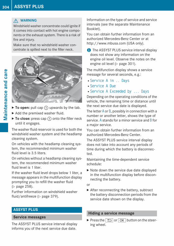
G WARNINGWindshield washer concentrate could ignite ifit comes into contact with hot engine compo-nents or the exhaust system. There is a risk offire and injury.Make sure that no windshield washer con-centrate is spilled next to the filler neck.
X To open: pull cap : upwards by the tab.X Add the premixed washer fluid.X To close: press cap : onto the filler neck
until it engages.The washer fluid reservoir is used for both thewindshield washer system and the headlampcleaning system.On vehicles with the headlamp cleaning sys-tem, the recommended minimum washerfluid level is 3.5 liters.On vehicles without a headlamp cleaning sys-tem, the recommended minimum washerfluid level is 1 liter.If the washer fluid level drops below 1 liter, amessage appears in the multifunction displayprompting you to refill the washer fluid(Y page 258).Further information on windshield washerfluid/antifreeze (Y page 379).
ASSYST PLUS
Service messagesThe ASSYST PLUS service interval displayinforms you of the next service due date.
Information on the type of service and serviceintervals (see the separate MaintenanceBooklet).You can obtain further information from anauthorized Mercedes-Benz Center or athttp://www.mbusa.com (USA only).
i The ASSYST PLUS service interval displaydoes not show any information on theengine oil level. Observe the notes on theengine oil level (Y page 301).
The multifunction display shows a servicemessage for several seconds, e.g.:RService A in .. DaysRService A DueRService A Exceeded by ... DaysDepending on the operating conditions of thevehicle, the remaining time or distance untilthe next service due date is displayed.The letter A or B, possibly in connection with anumber or another letter, shows the type ofservice. A stands for a minor service and B fora major service.You can obtain further information from anauthorized Mercedes-Benz Center.The ASSYST PLUS service interval displaydoes not take into account any periods oftime during which the battery is disconnec-ted.Maintaining the time-dependent serviceschedule:X Note down the service due date displayed
in the multifunction display before discon-necting the battery.
orX After reconnecting the battery, subtract
the battery disconnection periods from theservice date shown on the display.
Hiding a service messageX Press the % or a button on the steer-
ing wheel.
304 ASSYST PLUSM
aint
enan
ce a
nd c
are
Displaying service messagesX Switch on the ignition.X Press the = or ; button on the steer-
ing wheel to select the Serv. menu.X Press the 9 or : button to select theASSYST PLUS submenu and confirm bypressing the a button.The service due date appears in the multi-function display.
Information about Service
Resetting the ASSYST PLUS serviceinterval display
! If the ASSYST PLUS service interval dis-play has been inadvertently reset, this set-ting can be corrected at a qualified special-ist workshop.Have service work carried out as describedin the Maintenance Booklet. This may oth-erwise lead to increased wear and damageto the major assemblies or the vehicle.
A qualified specialist workshop, e.g. anauthorized Mercedes-Benz Center, will resetthe ASSYST PLUS service interval displayafter the service work has been carried out.You can also obtain further information onmaintenance work, for example.
Special service requirementsThe specified maintenance interval takes onlythe normal operation of the vehicle intoaccount. Under arduous operating conditionsor increased load on the vehicle, mainte-nance work must be carried out more fre-quently, for example:Rregular city driving with frequent intermedi-
ate stopsRif the vehicle is primarily used to travel
short distances
Ruse in mountainous terrain or on poor roadsurfacesRif the engine is often left idling for long peri-
odsUnder these or similar conditions, have, forexample, the air filter, engine oil and oil filterreplaced or changed more frequently. Underarduous operating conditions, the tires mustbe checked more often. Further informationcan be obtained at a qualified specialist work-shop, e.g. an authorized Mercedes-Benz Cen-ter.
Driving abroadAn extensive Mercedes-Benz Service networkis also available in other countries. You canobtain further information from any author-ized Mercedes-Benz Center.
Care
General notes! For cleaning your vehicle, do not use any
of the following:Rdry, rough or hard clothsRabrasive cleaning agentsRsolventsRcleaning agents containing solventsDo not scrub.Do not touch the surfaces or protectivefilms with hard objects, e.g. a ring or icescraper. You could otherwise scratch ordamage the surfaces and protective film.
H Environmental noteDispose of empty packaging and cleaningcloths in an environmentally responsible man-ner.
! Do not park the vehicle for an extendedperiod straight after cleaning it, particularlyafter having cleaned the wheels with wheelcleaner. Wheel cleaners could causeincreased corrosion of the brake discs andbrake pads/linings. For this reason, you
Care 305
Mai
nten
ance
and
car
e
Z
should drive for a few minutes after clean-ing. Braking heats the brake discs and thebrake pads/linings, thus drying them. Thevehicle can then be parked.
Regular care of your vehicle is a condition forretaining the quality in the long term.Use care products and cleaning agents rec-ommended and approved by Mercedes-Benz.
Exterior care
Automatic car wash
G WARNINGBraking efficiency is reduced after washingthe vehicle. There is a risk of an accident.After the vehicle has been washed, brakecarefully while paying attention to the trafficconditions until full braking power is restored.
! If DISTRONIC PLUS or the HOLD functionis activated, the vehicle brakes automati-cally in certain situations. To prevent dam-age to the vehicle, deactivate DISTRONICPLUS and the HOLD function in the follow-ing or other similar situations:Rwhen towing the vehicleRin the car wash
! Never clean your vehicle in a TouchlessAutomatic Car Wash as these use specialcleaning agents. These cleaning agents candamage the paintwork or plastic parts.
! Make sure that the automatic transmis-sion is in position N when washing yourvehicle in a tow-through car wash. The vehi-cle could be damaged if the transmission isin another position.
! Make sure that:Rthe side windows and the sliding sunroof
are fully closed.Rthe ventilation/heating is switched off
(the OFF button has been pressed).Rthe windshield wiper switch is in position
0.
Otherwise, the vehicle might be damaged.You can wash the vehicle in an automatic carwash from the very start.If the vehicle is very dirty, pre-wash it beforecleaning it in an automatic car wash.After using an automatic car wash, wipe offwax from the windshield and the wiperblades. This will prevent smears and reducewiping noises caused by residue on the wind-shield.
Washing by handIn some countries, washing by hand is onlyallowed at specially equipped washing bays.Observe the legal requirements in all coun-tries concerned.X Do not use hot water and do not wash the
vehicle in direct sunlight.X Use a soft sponge to clean.X Use a mild cleaning agent, such as a car
shampoo approved by Mercedes-Benz.X Thoroughly hose down the vehicle with a
gentle jet of water.X Do not point the water jet directly towards
the air inlet.X Use plenty of water and rinse out the
sponge frequently.X Rinse the vehicle with clean water and dry
thoroughly with a chamois.X Do not let the cleaning agent dry on the
paintwork.When using the vehicle in winter, remove alltraces of road salt deposits carefully and assoon as possible.
Power washers
G WARNINGThe water jet from a circular jet nozzle (dirtblasters) can cause invisible exterior damageto the tires or chassis components. Compo-nents damaged in this way may fail unexpect-edly. There is a risk of an accident.
306 CareM
aint
enan
ce a
nd c
are
Do not use power washers with circular jetnozzles to clean the vehicle. Have damagedtires or chassis components replaced imme-diately.
! Always maintain a distance of at least11.8 in (30 cm) between the vehicle and thepower washer nozzle. Information aboutthe correct distance is available from theequipment manufacturer.Move the power washer nozzle aroundwhen cleaning your vehicle.Do not aim directly at any of the following:RtiresRdoor gaps, roof gaps, joints, etc.Relectrical componentsRbatteryRconnectorsRlightsRsealsRtrimRventilation slotsDamaged seals or electrical componentscan lead to leaks or failures.
Cleaning the wheels
G WARNINGThe water jet from a circular jet nozzle (dirtblasters) can cause invisible exterior damageto the tires or chassis components. Compo-nents damaged in this way may fail unexpect-edly. There is a risk of an accident.Do not use power washers with circular jetnozzles to clean the vehicle. Have damagedtires or chassis components replaced imme-diately.
! Do not use acidic wheel cleaning productsto remove brake dust. This could damagewheel bolts and brake components.
! Do not park the vehicle for an extendedperiod straight after cleaning it, particularlyafter having cleaned the wheels with wheelcleaner. Wheel cleaners could cause
increased corrosion of the brake discs andbrake pads/linings. For this reason, youshould drive for a few minutes after clean-ing. Braking heats the brake discs and thebrake pads/linings, thus drying them. Thevehicle can then be parked.
Cleaning the paintworkScratches, corrosive deposits, areas affectedby corrosion and damage caused by inade-quate care cannot always be completelyrepaired. In such cases, visit a qualified spe-cialist workshop.X Remove dirt immediately, where possible,
while avoiding rubbing too hard.X Soak insect remains with insect remover
and rinse off the treated areas afterwards.X Soak bird droppings with water and rinse
off the treated areas afterwards.X Remove coolant, brake fluid, tree resin,
oils, fuels and greases by rubbing gentlywith a cloth soaked in petroleum ether orlighter fluid.
X Use tar remover to remove tar stains.X Use silicone remover to remove wax.
! Do not affix:RstickersRfilmsRmagnetic plates or similar itemsto painted surfaces. You could otherwisedamage the paintwork.
If water no longer forms "beads" on the paintsurface, use the paint care products recom-mended and approved by Mercedes-Benz.This is the case approximately every three tofive months, depending on the climate con-ditions and the care product used.If the dirt has penetrated the paint surface orif the paintwork has become dull, then thepaintwork should be cleaned. Use the clean-ing product Paint Cleaner, which has beenapproved by Mercedes-Benz.Do not use these care products in the sun oron the hood while the hood is hot.
Care 307
Mai
nten
ance
and
car
e
Z
X Use a suitable touch-up stick, e.g. MBTouch-Up Stick, to repair slight damage tothe paintwork quickly and provisionally.
Matte finish careIf your vehicle has a clear matte finish,observe the following instructions in order toavoid damage to the paintwork due to incor-rect care.These notes also apply to light alloy wheelswith a clear matte finish.
! Never polish the vehicle or the light alloywheels. Polishing causes the finish toshine.
! The following may cause the paint tobecome shiny and thus reduce the matteeffect:RVigorous rubbing with unsuitable mate-
rials.RFrequent use of car washes.RWashing the vehicle in direct sunlight.
! Never use paint cleaner, buffing or pol-ishing products, or gloss preserver, e.g.wax. These products are only suitable forhigh-gloss surfaces. Their use on vehicleswith matte finish leads to considerable sur-face damage (shiny, spotted areas).Always have paintwork repairs carried outat a qualified specialist workshop.
! Do not use wash programs with a hot waxtreatment under any circumstances.
i The vehicle should preferably be washedby hand using a soft sponge, car shampooand plenty of water.
i Use only insect remover and car shampoofrom the range of approved Mercedes-Benzcare products.
Cleaning the windows
G WARNINGYou could become trapped by the windshieldwipers if they start moving while cleaning the
windshield or wiper blades. There is a risk ofinjury.Always switch off the windshield wipers andthe ignition before cleaning the windshield orwiper blades.
! Only fold the windshield wipers away fromthe windshield when vertical. Otherwise,you will damage the hood.
! Do not use dry cloths, abrasive products,solvents or cleaning agents containing sol-vents to clean the inside of the windows. Donot touch the insides of the windows withhard objects, e.g. an ice scraper or ring.There is otherwise a risk of damaging thewindows.
! Clean the water drainage channels of thewindshield and the rear window at regularintervals. Deposits such as leaves, petalsand pollen may under certain circumstan-ces prevent water from draining away. Thiscan lead to corrosion damage and damageto electronic components.
X Clean the inside and outside of the win-dows with a damp cloth and a cleaningproduct that is recommended andapproved by Mercedes-Benz.
Cleaning wiper blades
G WARNINGYou could become trapped by the windshieldwipers if they start moving while cleaning thewindshield or wiper blades. There is a risk ofinjury.Always switch off the windshield wipers andthe ignition before cleaning the windshield orwiper blades.
! Only fold the windshield wipers away fromthe windshield when vertical. Otherwise,you will damage the hood.
! Do not pull the wiper blade. Otherwise,the wiper blade could be damaged.
308 CareM
aint
enan
ce a
nd c
are
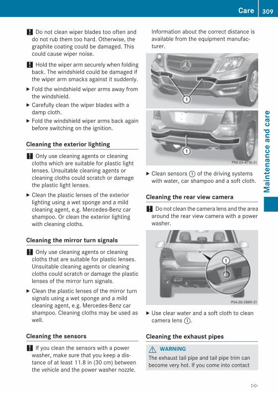
! Do not clean wiper blades too often anddo not rub them too hard. Otherwise, thegraphite coating could be damaged. Thiscould cause wiper noise.
! Hold the wiper arm securely when foldingback. The windshield could be damaged ifthe wiper arm smacks against it suddenly.
X Fold the windshield wiper arms away fromthe windshield.
X Carefully clean the wiper blades with adamp cloth.
X Fold the windshield wiper arms back againbefore switching on the ignition.
Cleaning the exterior lighting
! Only use cleaning agents or cleaningcloths which are suitable for plastic lightlenses. Unsuitable cleaning agents orcleaning cloths could scratch or damagethe plastic light lenses.
X Clean the plastic lenses of the exteriorlighting using a wet sponge and a mildcleaning agent, e.g. Mercedes-Benz carshampoo. Or clean the exterior lightingwith cleaning cloths.
Cleaning the mirror turn signals
! Only use cleaning agents or cleaningcloths that are suitable for plastic lenses.Unsuitable cleaning agents or cleaningcloths could scratch or damage the plasticlenses of the mirror turn signals.
X Clean the plastic lenses of the mirror turnsignals using a wet sponge and a mildcleaning agent, e.g. Mercedes-Benz carshampoo. Cleaning cloths may be used aswell.
Cleaning the sensors
! If you clean the sensors with a powerwasher, make sure that you keep a dis-tance of at least 11.8 in (30 cm) betweenthe vehicle and the power washer nozzle.
Information about the correct distance isavailable from the equipment manufac-turer.
X Clean sensors : of the driving systemswith water, car shampoo and a soft cloth.
Cleaning the rear view camera
! Do not clean the camera lens and the areaaround the rear view camera with a powerwasher.
X Use clear water and a soft cloth to cleancamera lens :.
Cleaning the exhaust pipes
G WARNINGThe exhaust tail pipe and tail pipe trim canbecome very hot. If you come into contact
Care 309
Mai
nten
ance
and
car
e
Z
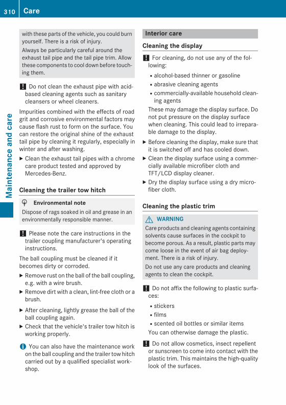
with these parts of the vehicle, you could burnyourself. There is a risk of injury.Always be particularly careful around theexhaust tail pipe and the tail pipe trim. Allowthese components to cool down before touch-ing them.
! Do not clean the exhaust pipe with acid-based cleaning agents such as sanitarycleansers or wheel cleaners.
Impurities combined with the effects of roadgrit and corrosive environmental factors maycause flash rust to form on the surface. Youcan restore the original shine of the exhausttail pipe by cleaning it regularly, especially inwinter and after washing.X Clean the exhaust tail pipes with a chrome
care product tested and approved byMercedes-Benz.
Cleaning the trailer tow hitch
H Environmental noteDispose of rags soaked in oil and grease in anenvironmentally responsible manner.
! Please note the care instructions in thetrailer coupling manufacturer's operatinginstructions.
The ball coupling must be cleaned if itbecomes dirty or corroded.X Remove rust on the ball of the ball coupling,
e.g. with a wire brush.X Remove dirt with a clean, lint-free cloth or a
brush.X After cleaning, lightly grease the ball of the
ball coupling again.X Check that the vehicle's trailer tow hitch is
working properly.
i You can also have the maintenance workon the ball coupling and the trailer tow hitchcarried out by a qualified specialist work-shop.
Interior care
Cleaning the display
! For cleaning, do not use any of the fol-lowing:Ralcohol-based thinner or gasolineRabrasive cleaning agentsRcommercially-available household clean-
ing agentsThese may damage the display surface. Donot put pressure on the display surfacewhen cleaning. This could lead to irrepara-ble damage to the display.
X Before cleaning the display, make sure thatit is switched off and has cooled down.
X Clean the display surface using a commer-cially available microfiber cloth andTFT/LCD display cleaner.
X Dry the display surface using a dry micro-fiber cloth.
Cleaning the plastic trim
G WARNINGCare products and cleaning agents containingsolvents cause surfaces in the cockpit tobecome porous. As a result, plastic parts maycome loose in the event of air bag deploy-ment. There is a risk of injury.Do not use any care products and cleaningagents to clean the cockpit.
! Do not affix the following to plastic surfa-ces:RstickersRfilmsRscented oil bottles or similar itemsYou can otherwise damage the plastic.
! Do not allow cosmetics, insect repellentor sunscreen to come into contact with theplastic trim. This maintains the high-qualitylook of the surfaces.
310 CareM
aint
enan
ce a
nd c
are
X Wipe the plastic trim with a damp, lint-freecloth, e.g. a microfiber cloth.
X Heavy soiling: use care and cleaning prod-ucts recommended and approved byMercedes-Benz.The surface may change color temporarily.Wait until the surface is dry again.
Cleaning the steering wheel and gear orselector leverX Thoroughly wipe with a damp cloth or use
leather care agents that have been recom-mended and approved by Mercedes-Benz.
Cleaning genuine wood and trim ele-ments
! Do not use solvent-based cleaning agentssuch as tar remover, wheel cleaners, pol-ishes or waxes. There is otherwise a risk ofdamaging the surface.
! Do not use chrome polish on trim pieces.The trim pieces have a chrome look but aremostly made of anodized aluminum andcan lose their shine if chrome polish isused. Use a damp, lint-free cloth insteadwhen cleaning the trim pieces.If the chrome-plated trim pieces are verydirty, you can use a chrome polish. If youare unsure as to whether the trim piecesare chrome-plated or not, consult anauthorized Mercedes-Benz Center.
X Wipe the wooden trim and trim pieces witha damp, lint-free cloth, e.g. a microfibercloth.
X Heavy soiling: use car care and cleaningproducts recommended and approved byMercedes-Benz.
Cleaning the seat covers
General notes! Do not use microfiber cloths to clean gen-
uine leather, artificial leather or DINAMICA
covers. If used often, these can damage thecover.
i Note that regular care is essential toensure that the appearance and comfort ofthe covers is retained over time.
Genuine leather seat coversLeather is a natural product.It exhibits natural surface characteristics, forexample:Rdifferences in the textureRmarks caused by growth and injuryRslight nuances of colorThese are characteristics of leather and notmaterial defects.
! To retain the natural appearance of theleather, observe the following cleaninginstructions:RClean genuine leather covers carefully
with a damp cloth and then wipe the cov-ers down with a dry cloth.RMake sure that the leather does not
become soaked. It may otherwisebecome rough and cracked.ROnly use leather care agents that have
been tested and approved by Mercedes-Benz. You can obtain these from a quali-fied specialist workshop.
Seat covers of other materials! Observe the following when cleaning:Rclean artificial leather covers with a cloth
moistened with a solution containing 1%detergent (e.g. dish washing liquid).Rclean cloth covers with a microfiber cloth
moistened with a solution containing 1%detergent (e.g. dish washing liquid). Rubcarefully and always wipe entire seat sec-tions to avoid leaving visible lines. Leavethe seat to dry afterwards. Cleaningresults depend on the type of dirt andhow long it has been there.Rclean DINAMICA covers with a damp
cloth. Make sure that you wipe entire
Care 311
Mai
nten
ance
and
car
e
Z
seat sections to avoid leaving visiblelines.
Cleaning the seat belts
G WARNINGSeat belts can become severely weakened ifbleached or dyed. This could cause the seatbelts to tear or fail, for instance, in the event ofan accident. This poses an increased risk ofinjury or fatal injury.Never bleach or dye the seat belts.
! Do not clean the seat belts using chemicalcleaning agents. Do not dry the seat beltsby heating at temperatures above 176 ‡(80 †) or in direct sunlight.
X Use clean, lukewarm water and soap solu-tion.
Cleaning the headliner and carpetsX Headliner: if it is very dirty, use a soft brush
or a cleaning agent recommended andapproved by Mercedes-Benz.
X Carpets: use the carpet and textile clean-ing agents recommended and approved byMercedes-Benz.
312 CareM
aint
enan
ce a
nd c
are

Useful information ............................ 314Where will I find...? ........................... 314Flat tire .............................................. 314Battery (vehicle) ................................ 319Jump-starting .................................... 323Towing and tow-starting .................. 325Fuses .................................................. 328
313
Road
side
Ass
ista
nce
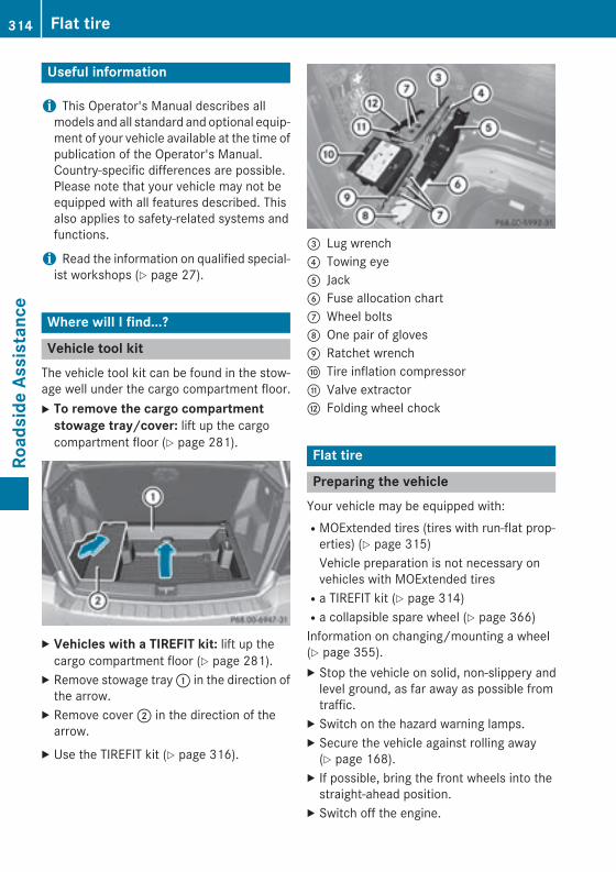
Useful information
i This Operator's Manual describes allmodels and all standard and optional equip-ment of your vehicle available at the time ofpublication of the Operator's Manual.Country-specific differences are possible.Please note that your vehicle may not beequipped with all features described. Thisalso applies to safety-related systems andfunctions.
i Read the information on qualified special-ist workshops (Y page 27).
Where will I find...?
Vehicle tool kitThe vehicle tool kit can be found in the stow-age well under the cargo compartment floor.X To remove the cargo compartment
stowage tray/cover: lift up the cargocompartment floor (Y page 281).
X Vehicles with a TIREFIT kit: lift up thecargo compartment floor (Y page 281).
X Remove stowage tray : in the direction ofthe arrow.
X Remove cover ; in the direction of thearrow.
X Use the TIREFIT kit (Y page 316).
= Lug wrench? Towing eyeA JackB Fuse allocation chartC Wheel boltsD One pair of glovesE Ratchet wrenchF Tire inflation compressorG Valve extractorH Folding wheel chock
Flat tire
Preparing the vehicleYour vehicle may be equipped with:RMOExtended tires (tires with run-flat prop-
erties) (Y page 315)Vehicle preparation is not necessary onvehicles with MOExtended tiresRa TIREFIT kit (Y page 314)Ra collapsible spare wheel (Y page 366)Information on changing/mounting a wheel(Y page 355).X Stop the vehicle on solid, non-slippery and
level ground, as far away as possible fromtraffic.
X Switch on the hazard warning lamps.X Secure the vehicle against rolling away
(Y page 168).X If possible, bring the front wheels into the
straight-ahead position.X Switch off the engine.
314 Flat tireRo
adsi
de A
ssis
tanc
e
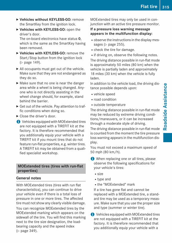
X Vehicles without KEYLESS-GO: removethe SmartKey from the ignition lock.
X Vehicles with KEYLESS-GO: open thedriver's door.The on-board electronics have status 0,which is the same as the SmartKey havingbeen removed.
X Vehicles with KEYLESS-GO: remove theStart/Stop button from the ignition lock(Y page 149).
X All occupants must get out of the vehicle.Make sure that they are not endangered asthey do so.
X Make sure that no one is near the dangerarea while a wheel is being changed. Any-one who is not directly assisting in thewheel change should, for example, standbehind the barrier.
X Get out of the vehicle. Pay attention to traf-fic conditions when doing so.
X Close the driver's door.i Vehicles equipped with MOExtended tires
are not equipped with a TIREFIT kit at thefactory. It is therefore recommended thatyou additionally equip your vehicle with aTIREFIT kit if you mount tires that do notfeature run-flat properties, e.g. winter tires.A TIREFIT kit may be obtained from a quali-fied specialist workshop.
MOExtended tires (tires with run-flatproperties)
General notesWith MOExtended tires (tires with run flatcharacteristics), you can continue to driveyour vehicle even if there is a total loss ofpressure in one or more tires. The affectedtire must not show any clearly visible damage.You can recognize MOExtended tires by theMOExtended marking which appears on thesidewall of the tire. You will find this markingnext to the tire size designation, the load-bearing capacity and the speed index(Y page 349).
MOExtended tires may only be used in con-junction with an active tire pressure monitor.If a pressure loss warning message appears in the multifunction display:Robserve the instructions in the display mes-
sages (Y page 255).Rcheck the tire for damage.Rif driving on, observe the following notes.The driving distance possible in run-flat modeis approximately 50 miles (80 km) when thevehicle is partially laden and approximately18 miles (30 km) when the vehicle is fullyladen.In addition to the vehicle load, the driving dis-tance possible depends upon:Rvehicle speedRroad conditionRoutside temperatureThe driving distance possible in run-flat modemay be reduced by extreme driving condi-tions/maneuvers, or it can be increasedthrough a moderate style of driving.The driving distance possible in run-flat modeis counted from the moment the tire pressureloss warning appears in the multifunction dis-play.You must not exceed a maximum speed of50 mph (80 km/h).
i When replacing one or all tires, pleaseobserve the following specifications foryour vehicle's tires:RsizeRtype andRthe "MOExtended" markIf a tire has gone flat and cannot bereplaced with a MOExtended tire, a stand-ard tire may be used as a temporary meas-ure. Make sure that you use the proper sizeand type (summer or winter tire).
i Vehicles equipped with MOExtended tiresare not equipped with a TIREFIT kit at thefactory. It is therefore recommended thatyou additionally equip your vehicle with a
Flat tire 315
Road
side
Ass
ista
nce

TIREFIT kit if you mount tires that do notfeature run-flat properties, e.g. winter tires.A TIREFIT kit may be obtained from a quali-fied specialist workshop.
Important safety notes
G WARNINGWhen driving in emergency mode, the drivingcharacteristics deteriorate, e.g. when corner-ing, accelerating quickly and when braking.There is a risk of an accident.Do not exceed the stated maximum speed.Avoid abrupt steering and driving maneuvers,and driving over obstacles (curbs, potholes,off-road). This applies in particular to a ladenvehicle.Stop driving in emergency mode if:Ryou hear banging noises.Rthe vehicle starts to shake.Ryou see smoke and smell rubber.RESP® is intervening constantly.Rthere are tears in the sidewalls of the tire.After driving in emergency mode, have thewheel rims checked at a qualified specialistworkshop with regard to their further use. Thedefective tire must be replaced in every case.
TIREFIT kit
Important safety notesTIREFIT is a tire sealant.You can use TIREFIT to seal punctures of up to0.16 in (4 mm), particularly those in the tiretread. You can use TIREFIT at outside tem-peratures down to Ò4 ‡ (Ò20 †).
G WARNINGIn the following situations, the tire sealant isunable to provide sufficient breakdown assis-tance, as it is unable to seal the tire properly:Rthere are cuts or punctures in the tire larger
than those mentioned above.Rthe wheel rim is damaged.Ryou have driven at very low tire pressures or
on a flat tire.There is a risk of an accident.Do not drive the vehicle. Contact a qualifiedspecialist workshop.
G WARNINGThe tire sealant is harmful and causes irrita-tion. It must not come into contact with yourskin, eyes or clothing or be swallowed. Do notinhale TIREFIT fumes. Keep tire sealant awayfrom children. There is a risk of injury.If you come into contact with the tire sealant,observe the following:RRinse off the tire sealant from your skin
immediately with water.RIf the tire sealant comes into contact with
your eyes, immediately rinse them thor-oughly with clean water.RIf tire sealant is swallowed, immediately
rinse your mouth out thoroughly and drinkplenty of water. Do not induce vomiting,and seek medical attention immediately.RImmediately change out of clothing which
has come into contact with tire sealant.RIf an allergic reaction occurs, seek medical
attention immediately.
! Do not operate the tire inflation compres-sor for longer than eight minutes at a timewithout a break. It may otherwise overheat.The tire inflation compressor can be oper-ated again once it has cooled down.
Comply with the manufacturer’s safetyinstructions on the sticker on the tire inflationcompressor.
316 Flat tireRo
adsi
de A
ssis
tanc
e
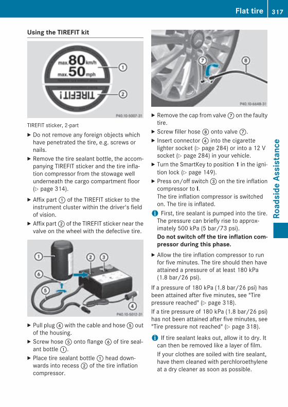
Using the TIREFIT kit
TIREFIT sticker, 2-partX Do not remove any foreign objects which
have penetrated the tire, e.g. screws ornails.
X Remove the tire sealant bottle, the accom-panying TIREFIT sticker and the tire infla-tion compressor from the stowage wellunderneath the cargo compartment floor(Y page 314).
X Affix part : of the TIREFIT sticker to theinstrument cluster within the driver's fieldof vision.
X Affix part ; of the TIREFIT sticker near thevalve on the wheel with the defective tire.
X Pull plug ? with the cable and hose A outof the housing.
X Screw hose A onto flange B of tire seal-ant bottle :.
X Place tire sealant bottle : head down-wards into recess ; of the tire inflationcompressor.
X Remove the cap from valve C on the faultytire.
X Screw filler hose D onto valve C.X Insert connector ? into the cigarette
lighter socket (Y page 284) or into a 12 Vsocket (Y page 284) in your vehicle.
X Turn the SmartKey to position 1 in the igni-tion lock (Y page 149).
X Press on/off switch = on the tire inflationcompressor to I.The tire inflation compressor is switchedon. The tire is inflated.
i First, tire sealant is pumped into the tire.The pressure can briefly rise to approx-imately 500 kPa (5 bar/73 psi).Do not switch off the tire inflation com-pressor during this phase.
X Allow the tire inflation compressor to runfor five minutes. The tire should then haveattained a pressure of at least 180 kPa(1.8 bar/26 psi).
If a pressure of 180 kPa (1.8 bar/26 psi) hasbeen attained after five minutes, see "Tirepressure reached" (Y page 318).If a tire pressure of 180 kPa (1.8 bar/26 psi)has not been attained after five minutes, see"Tire pressure not reached" (Y page 318).
i If tire sealant leaks out, allow it to dry. Itcan then be removed like a layer of film.If your clothes are soiled with tire sealant,have them cleaned with perchloroethyleneat a dry cleaner as soon as possible.
Flat tire 317
Road
side
Ass
ista
nce
Z
Tire pressure not reachedIf a pressure of 180 kPa (1.8 bar/26 psi) hasnot been attained after five minutes:X Switch off the tire inflation compressor.X Unscrew the filler hose from the valve of
the faulty tire.X Very slowly drive forwards or back up
approximately 30 ft (10 m).X Pump up the tire again.
After a maximum of five minutes the tirepressure must be at least 180 kPa (1.8 bar/26 psi).
G WARNINGIf the required tire pressure is not reachedafter the specified time, the tire is too badlydamaged. The tire sealant cannot repair thetire in this instance. Damaged tires and a tirepressure that is too low can significantlyimpair the vehicle's braking and driving char-acteristics. There is a risk of accident.Do not continue driving. Contact a qualifiedspecialist workshop.
Tire pressure reachedIf a tire pressure of 180 kPa (1.8 bar/26 psi)has been attained after five minutes:X Switch off the tire inflation compressor.X Unscrew the filler hose from the valve of
the faulty tire.
! After use, excess tire sealant may run outof the filler hose. This could cause stains.Therefore, place the filler hose in the plasticbag that contained the TIREFIT kit.
X Stow the tire sealant bottle and the tireinflation compressor.
X Pull away immediately.
G WARNINGA tire temporarily sealed with tire sealantimpairs the driving characteristics and is notsuitable for higher speeds. There is a risk ofaccident.
You should therefore adapt your driving styleaccordingly and drive carefully. Do not exceedthe specified maximum speed with a tire thathas been repaired using tire sealant.
The maximum speed for a tire sealed with tiresealant is 50 mph (80 km/h). The upper partof the TIREFIT sticker must be affixed to theinstrument cluster in the driver's field ofvision.X Stop after driving for approximately ten
minutes and check the tire pressure withthe tire inflation compressor.The tire pressure must now be at least130 kPa (1.3 bar/19 psi).
G WARNINGIf the required tire pressure is not reachedafter driving for a short period, the tire is toobadly damaged. The tire sealant cannot repairthe tire in this instance. Damaged tires and atire pressure that is too low can significantlyimpair the vehicle's braking and driving char-acteristics. There is a risk of accident.Do not continue driving. Contact a qualifiedspecialist workshop.
i In cases such as the one mentionedabove, contact an authorized Mercedes-Benz Center. Or call 1-800-FOR-MERCedes(in the USA) or 1-800-387-0100 (in Can-ada).
X Correct the tire pressure if it is still at least130 kPa (1.3 bar/19 psi). See the Tire andLoading Information placard on the driver'sside B-pillar or the tire pressure table in thefuel filler flap for values.
X To increase the tire pressure: switch onthe tire inflation compressor.
318 Flat tireRo
adsi
de A
ssis
tanc
e
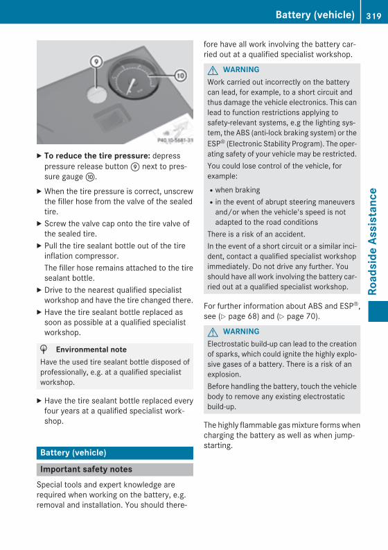
X To reduce the tire pressure: depresspressure release button E next to pres-sure gauge F.
X When the tire pressure is correct, unscrewthe filler hose from the valve of the sealedtire.
X Screw the valve cap onto the tire valve ofthe sealed tire.
X Pull the tire sealant bottle out of the tireinflation compressor.The filler hose remains attached to the tiresealant bottle.
X Drive to the nearest qualified specialistworkshop and have the tire changed there.
X Have the tire sealant bottle replaced assoon as possible at a qualified specialistworkshop.
H Environmental noteHave the used tire sealant bottle disposed ofprofessionally, e.g. at a qualified specialistworkshop.
X Have the tire sealant bottle replaced everyfour years at a qualified specialist work-shop.
Battery (vehicle)
Important safety notesSpecial tools and expert knowledge arerequired when working on the battery, e.g.removal and installation. You should there-
fore have all work involving the battery car-ried out at a qualified specialist workshop.
G WARNINGWork carried out incorrectly on the batterycan lead, for example, to a short circuit andthus damage the vehicle electronics. This canlead to function restrictions applying tosafety-relevant systems, e.g the lighting sys-tem, the ABS (anti-lock braking system) or theESP® (Electronic Stability Program). The oper-ating safety of your vehicle may be restricted.You could lose control of the vehicle, forexample:Rwhen brakingRin the event of abrupt steering maneuvers
and/or when the vehicle's speed is notadapted to the road conditions
There is a risk of an accident.In the event of a short circuit or a similar inci-dent, contact a qualified specialist workshopimmediately. Do not drive any further. Youshould have all work involving the battery car-ried out at a qualified specialist workshop.
For further information about ABS and ESP®,see (Y page 68) and (Y page 70).
G WARNINGElectrostatic build-up can lead to the creationof sparks, which could ignite the highly explo-sive gases of a battery. There is a risk of anexplosion.Before handling the battery, touch the vehiclebody to remove any existing electrostaticbuild-up.
The highly flammable gas mixture forms whencharging the battery as well as when jump-starting.
Battery (vehicle) 319
Road
side
Ass
ista
nce
Z
Always make sure that neither you nor thebattery is electrostatically charged. A build-up of electrostatic charge can be caused, forexample:Rby wearing clothing made from synthetic
fibersRdue to friction between clothing and seatsRif you push or pull the battery across the
carpet or other synthetic materialsRif you wipe the battery with a cloth
G WARNINGBattery acid is caustic. There is a risk of injury.Avoid contact with skin, eyes or clothing. Donot inhale any battery gases. Do not lean overthe battery. Keep children away from batter-ies. Wash away battery acid immediately withplenty of clean water and seek medical atten-tion.
G WARNINGDuring the charging process, a battery produ-ces hydrogen gas. If a short circuit occurs orsparks are created, the hydrogen gas canignite. There is a risk of an explosion.RMake sure that the positive terminal of a
connected battery does not come into con-tact with vehicle parts.RNever place metal objects or tools on a bat-
tery.RIt is important that you observe the descri-
bed order of the battery terminals whenconnecting and disconnecting a battery.RWhen jump-starting, make sure that the
battery poles with identical polarity areconnected.RIt is particularly important to observe the
described order when connecting and dis-connecting the jumper cables.RNever connect or disconnect the battery
terminals while the engine is running.
G WARNINGDuring charging and jump-starting, explosivegases can escape from the battery. There is arisk of an explosion.Particularly avoid fire, open flames, creatingsparks and smoking. Ensure there is sufficientventilation while charging and jump-starting.Do not lean over a battery.
H Environmental noteBatteries contain dangeroussubstances. It is against thelaw to dispose of them withthe household rubbish. Theymust be collected separatelyand recycled to protect theenvironment.Dispose of batteries in anenvironmentally friendlymanner. Take dischargedbatteries to a qualified spe-cialist workshop or a specialcollection point for used bat-teries.
! Have the battery checked regularly at aqualified specialist workshop.Observe the service intervals in the Main-tenance Booklet or contact a qualified spe-cialist workshop for more information.
! You should have all work involving thebattery carried out at a qualified specialistworkshop. In the exceptional case that it isnecessary for you to disconnect the batteryyourself, make sure that:Ryou switch off the engine and remove the
SmartKey. On vehicles with KEYLESS-GO, ensure that the ignition is switchedoff. Check that all the indicator lamps inthe instrument cluster are off. Otherwise,electronic components, such as thealternator, may be damaged.Ryou first remove the negative terminal
clamp and then the positive terminalclamp. Never swap the terminal clamps.
320 Battery (vehicle)Ro
adsi
de A
ssis
tanc
e
Otherwise, the vehicle's electronic sys-tem may be damaged.Rthe transmission is locked in position P
after disconnecting the battery. The vehi-cle is secured against rolling away. Youcan then no longer move the vehicle.
The battery and the cover of the positiveterminal clamp must be installed securelyduring operation.
Comply with safety precautions and take pro-tective measures when handling batteries.
Risk of explosion.
Fire, open flames and smoking areprohibited when handling the bat-tery. Avoid creating sparks.
Battery acid is caustic. Avoid con-tact with skin, eyes or clothing.Wear suitable protective clothing,especially gloves, apron and face-guard.Rinse any acid spills immediatelywith clear water. Contact a physi-cian if necessary.Wear eye protection.
Keep children away.
Observe this Operator's Manual.
In order for the battery to achieve the maxi-mum possible service life, it must always besufficiently charged.Have the battery condition of charge checkedmore frequently if you use the vehicle mainlyfor short trips or if you leave it standing idlefor a lengthy period. Consult a qualified spe-
cialist workshop if you wish to leave yourvehicle parked for a long period of time.Like other batteries, the vehicle battery maydischarge over time if you do not use thevehicle. In this case, have the battery discon-nected at a qualified specialist workshop. Youcan also charge the battery with a chargerrecommended by Mercedes-Benz. Contact aqualified specialist workshop for further infor-mation.
i Remove the SmartKey if you park thevehicle and do not require any electricalconsumers. The vehicle will then use verylittle energy, thus conserving batterypower.
i If the power supply has been interrupted,e.g. if you reconnect the battery, you willhave to:Rset the clock; see the separate operating
instructions.On vehicles with COMAND and a naviga-tion system, the clock is set automati-cally.Rreset the panorama roof with power tilt/
sliding panel. (Y page 97)Rreset the function for folding the exterior
mirrors in/out automatically by foldingthe mirrors out once (Y page 110)12.
Charging the battery
G WARNINGDuring charging and jump-starting, explosivegases can escape from the battery. There is arisk of an explosion.Particularly avoid fire, open flames, creatingsparks and smoking. Ensure there is sufficientventilation while charging and jump-starting.Do not lean over a battery.
G WARNINGBattery acid is caustic. There is a risk of injury.
12 This function is only available in vehicles for Canada.
Battery (vehicle) 321
Road
side
Ass
ista
nce
Z
Avoid contact with skin, eyes or clothing. Donot inhale any battery gases. Do not lean overthe battery. Keep children away from batter-ies. Wash away battery acid immediately withplenty of clean water and seek medical atten-tion.
G WARNINGA discharged battery can freeze at tempera-tures below freezing point. When jump-start-ing the vehicle or charging the battery, gasescan escape from the battery. There is a risk ofan explosion.Allow the frozen battery to thaw out beforecharging it or jump-starting.
! Only charge the installed battery with abattery charger which has been tested andapproved by Mercedes-Benz. These batterychargers allow the battery to be chargedwhile still installed in the vehicle.
! Only use battery chargers with a maxi-mum charging voltage of 14.8 V.
! Only charge the battery using the jump-starting connection point.
The jump-starting connection point is in theengine compartment (Y page 323).X Open the hood.X Connect the battery charger to the positive
terminal and ground point in the sameorder as when connecting the donor bat-tery in the jump-starting procedure(Y page 323).
X Read the battery charger's operatinginstructions before charging the battery.
322 Battery (vehicle)Ro
adsi
de A
ssis
tanc
e
Jump-starting
For the jump-starting procedure, use only the jump-starting connection point, consisting of apositive terminal and a ground point, in the engine compartment.
G WARNINGBattery acid is caustic. There is a risk of injury.Avoid contact with skin, eyes or clothing. Do not inhale any battery gases. Do not lean over thebattery. Keep children away from batteries. Wash away battery acid immediately with plenty ofclean water and seek medical attention.
G WARNINGDuring charging and jump-starting, explosive gases can escape from the battery. There is a riskof an explosion.Particularly avoid fire, open flames, creating sparks and smoking. Ensure there is sufficient ven-tilation while charging and jump-starting. Do not lean over a battery.
G WARNINGDuring the charging process, a battery produces hydrogen gas. If a short circuit occurs or sparksare created, the hydrogen gas can ignite. There is a risk of an explosion.RMake sure that the positive terminal of a connected battery does not come into contact with
vehicle parts.RNever place metal objects or tools on a battery.RIt is important that you observe the described order of the battery terminals when connecting
and disconnecting a battery.RWhen jump-starting, make sure that the battery poles with identical polarity are connected.RIt is particularly important to observe the described order when connecting and disconnecting
the jumper cables.RNever connect or disconnect the battery terminals while the engine is running.
G WARNINGNon-combusted fuel can collect in the exhaust system and ignite. There is a risk of fire. Avoidrepeated and lengthy starting attempts.
! Vehicles with a gasoline engine: avoid repeated and lengthy starting attempts. Other-wise, the catalytic converter could be damaged by non-combusted fuel.
Do not start the vehicle using a rapid charging device. If your vehicle's battery is discharged,the engine can be jump-started from another vehicle or from a second battery using jumpercables. Observe the following points:RThe battery is not accessible in all vehicles. If the other vehicle's battery is not accessible,
jump-start the vehicle using a second battery or a jump-starting device.RVehicles with a gasoline engine: only jump-start the vehicle when the engine and exhaust
system are cold.RDo not start the engine if the battery is frozen. Let the battery thaw first.RJump-starting may only be performed from batteries with a nominal voltage of 12 V.
Jump-starting 323
Road
side
Ass
ista
nce
Z
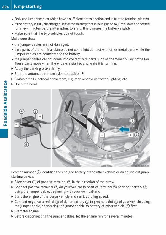
ROnly use jumper cables which have a sufficient cross-section and insulated terminal clamps.RIf the battery is fully discharged, leave the battery that is being used to jump-start connected
for a few minutes before attempting to start. This charges the battery slightly.RMake sure that the two vehicles do not touch.Make sure that:Rthe jumper cables are not damaged.Rbare parts of the terminal clamp do not come into contact with other metal parts while the
jumper cables are connected to the battery.Rthe jumper cables cannot come into contact with parts such as the V-belt pulley or the fan.
These parts move when the engine is started and while it is running.X Apply the parking brake firmly.X Shift the automatic transmission to position P.X Switch off all electrical consumers, e.g. rear window defroster, lighting, etc.X Open the hood.
Position number B identifies the charged battery of the other vehicle or an equivalent jump-starting device.X Slide cover : of positive terminal ; in the direction of the arrow.X Connect positive terminal ; on your vehicle to positive terminal = of donor battery B
using the jumper cable, beginning with your own battery.X Start the engine of the donor vehicle and run it at idling speed.X Connect negative terminal ? of donor battery B to ground point A of your vehicle using
the jumper cable, connecting the jumper cable to battery of other vehicle B first.X Start the engine.X Before disconnecting the jumper cables, let the engine run for several minutes.
324 Jump-startingRo
adsi
de A
ssis
tanc
e
X First, remove the jumper cables from ground point A and negative terminal ?, then frompositive clamp ; and positive terminal =. Begin each time at the contacts on your ownvehicle first.
X Close cover : of positive terminal ; after removing the jumper cables.X Have the battery checked at a qualified specialist workshop.
i Jump-starting is not considered to be a normal operating condition.
i Jumper cables and further information regarding jump-starting can be obtained at anyqualified specialist workshop.
Towing and tow-starting
Important safety notes
G WARNINGYou can no longer steer the vehicle if thesteering wheel lock has been engaged. Thereis a risk of an accident.Always switch off the ignition when towing thevehicle with a tow cable or a tow bar.
G WARNINGWhen towing or tow-starting another vehicleand its weight is greater than the permissiblegross weight of your vehicle, the:Rthe towing eye could detach itselfRthe vehicle/trailer combination could roll-
over.There is a risk of an accident.When towing or tow-starting another vehicle,its weight should not be greater than the per-missible gross weight of your vehicle.
Details on the permissible gross vehicleweight of your vehicle can be found on thevehicle identification plate (Y page 372).
! If DISTRONIC PLUS or the HOLD functionis activated, the vehicle brakes automati-cally in certain situations.
To prevent damage to the vehicle, deacti-vate DISTRONIC PLUS and the HOLD func-tion in the following or other similar situa-tions:Rwhen towing the vehicleRin the car wash
! The vehicle can be towed a maximum of30 miles (50km). The towing speed of30 mph (50 km/h) must not be exceeded.If the vehicle has to be towed more than30 miles (50km), the entire vehicle must beraised and transported.
! Only secure the tow rope or tow bar at thetowing eyes. Otherwise, the vehicle couldbe damaged.
! Do not use the towing eyes for recoverypurposes as this could damage the vehicle.If in doubt, recover the vehicle with a crane.
! When towing, pull away slowly andsmoothly. If the tractive power is too high,the vehicles could be damaged.
! Do not tow with sling-type equipment.This could damage the vehicle.
! On vehicles with KEYLESS-GO, use theSmartKey instead of the Start/Stop but-ton. Turn the SmartKey to position 2 in theignition lock and shift the automatic trans-mission to N. Then, turn the SmartKey backto 0 and leave it in the ignition lock.
It is better to have the vehicle transportedthan to have it towed away.
Towing and tow-starting 325
Road
side
Ass
ista
nce
Z
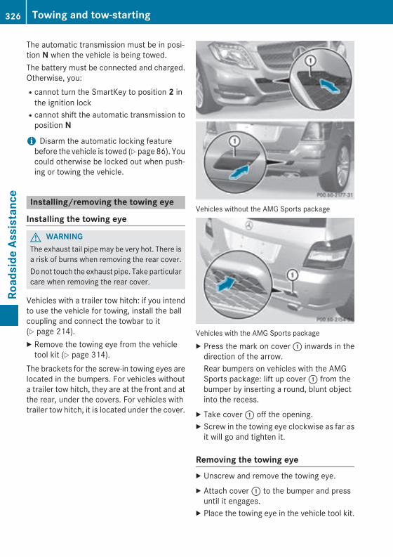
The automatic transmission must be in posi-tion N when the vehicle is being towed.The battery must be connected and charged.Otherwise, you:Rcannot turn the SmartKey to position 2 in
the ignition lockRcannot shift the automatic transmission to
position N
i Disarm the automatic locking featurebefore the vehicle is towed (Y page 86). Youcould otherwise be locked out when push-ing or towing the vehicle.
Installing/removing the towing eye
Installing the towing eye
G WARNINGThe exhaust tail pipe may be very hot. There isa risk of burns when removing the rear cover.Do not touch the exhaust pipe. Take particularcare when removing the rear cover.
Vehicles with a trailer tow hitch: if you intendto use the vehicle for towing, install the ballcoupling and connect the towbar to it(Y page 214).X Remove the towing eye from the vehicle
tool kit (Y page 314).The brackets for the screw-in towing eyes arelocated in the bumpers. For vehicles withouta trailer tow hitch, they are at the front and atthe rear, under the covers. For vehicles withtrailer tow hitch, it is located under the cover.
Vehicles without the AMG Sports package
Vehicles with the AMG Sports packageX Press the mark on cover : inwards in the
direction of the arrow.Rear bumpers on vehicles with the AMGSports package: lift up cover : from thebumper by inserting a round, blunt objectinto the recess.
X Take cover : off the opening.X Screw in the towing eye clockwise as far as
it will go and tighten it.
Removing the towing eyeX Unscrew and remove the towing eye.X Attach cover : to the bumper and press
until it engages.X Place the towing eye in the vehicle tool kit.
326 Towing and tow-startingRo
adsi
de A
ssis
tanc
e
Towing a vehicle with both axles onthe ground
It is important that you observe the safetyinstructions when towing away your vehicle(Y page 325).X Switch on the hazard warning lamps
(Y page 119).i When towing with the hazard warning
lamps switched on, use the combinationswitch as usual to signal a change of direc-tion. In this case, only the indicator lampsfor the direction of travel flash. After reset-ting the combination switch, the hazardwarning lamp starts flashing again.
X Turn the SmartKey to position 2 in the igni-tion lock.
X When the vehicle is stationary, depress thebrake pedal and keep it depressed.
X Shift the automatic transmission to posi-tion N.
X Release the brake pedal.X Release the parking brake.
Towing the vehicle with the rear axleraised
Only possible for vehicles without 4MATIC.When towing your vehicle with the rear axleraised, it is important that you observe thesafety instructions (Y page 325).
! The ignition must be switched off if youare towing the vehicle with the rear axleraised. Intervention by ESP® could other-wise damage the brake system.
X Bring the front wheels into the straight-ahead position.
X Switch on the hazard warning lamps(Y page 119).
X Turn the SmartKey to position 0 in the igni-tion lock and remove the SmartKey fromthe ignition lock.
X When leaving the vehicle, take the Smart-Key or the KEYLESS-GO key with you.
Transporting the vehicleThe towing eyes or trailer tow hitch can beused to pull the vehicle onto a trailer or trans-porter if you wish to transport it.X Turn the SmartKey to position 2 in the igni-
tion lock.X Shift the automatic transmission to posi-
tion N.
As soon as the vehicle has been loaded:X Prevent the vehicle from rolling away by
applying the parking brake.X Shift the automatic transmission to posi-
tion P.X Turn the SmartKey to position 0 in the igni-
tion lock and remove the SmartKey fromthe ignition lock.
X Secure the vehicle.
! You may only secure the vehicle by thewheels, not by parts of the vehicle such asaxle or steering components. Otherwise,the vehicle could be damaged.
Notes on 4MATIC vehicles! Vehicles with 4MATIC must not be towed
with either the front or the rear axle raised,as doing so will damage the transmission.
If the vehicle has transmission damage ordamage to the front or rear axle, have it trans-ported on a transporter or trailer.In the event of damage to the electrical systemIf the battery is defective, the automatictransmission will be locked in position P. Toshift the automatic transmission to positionN, you must provide power to the vehicle's
Towing and tow-starting 327
Road
side
Ass
ista
nce
Z
electrical system in the same way as whenjump-starting (Y page 323).Have the vehicle transported on a transporteror trailer.
Tow-starting (emergency enginestarting)
! Vehicles with automatic transmissionmust not be started by tow-starting. Thiscould otherwise damage the transmission.
You can find information on "Jump-starting" at(Y page 323).
Fuses
Important safety notes
G WARNINGIf you manipulate or bridge a faulty fuse or ifyou replace it with a fuse with a higher amper-age, the electric cables could be overloaded.This could result in a fire. There is a risk of anaccident and injury.Always replace faulty fuses with the specifiednew fuses having the correct amperage.
! Only use fuses that have been approvedfor Mercedes-Benz vehicles and whichhave the correct fuse rating for the systemconcerned. Otherwise, components or sys-tems could be damaged.
The fuses in your vehicle serve to close downfaulty circuits. If a fuse blows, all the compo-nents on the circuit and their functions stopoperating.Blown fuses must be replaced with fuses ofthe same rating, which you can recognize bythe color and value. The fuse ratings are listedin the fuse allocation chart.If a newly inserted fuse also blows, have thecause traced and rectified at a qualified spe-cialist workshop, e.g. an authorizedMercedes-Benz Center.
Before changing a fuseX Secure the vehicle against rolling away
(Y page 168).X Switch off all electrical consumers.X Turn the SmartKey to position 0 in the igni-
tion lock and remove it (Y page 149).orX On vehicles with KEYLESS-GO, make sure
the ignition is switched off (Y page 149).All indicator lamps in the instrument clustermust be off.The fuses are located in various fuse boxes:RFuse box on the driver's side of the dash-
boardRFuse box in the engine compartment on the
left-hand side of the vehicle, when viewedin the direction of travelRFuse box in the stowage well under the
cargo compartment floor on the right-handside of the vehicle, when viewed in thedirection of travel
The fuse allocation chart is in the vehicle toolkit which is located in the stowage compart-ment under the cargo compartment floor(Y page 314).
Dashboard fuse box! Do not use a pointed object such as a
screwdriver to open the cover in the dash-board. You could damage the dashboard orthe cover.
! Make sure that no moisture can enter thefuse box when the cover is open.
! When closing the cover, make sure that itis lying correctly on the fuse box. Moistureseeping in or dirt could otherwise impairthe operation of the fuses.
328 FusesRo
adsi
de A
ssis
tanc
e
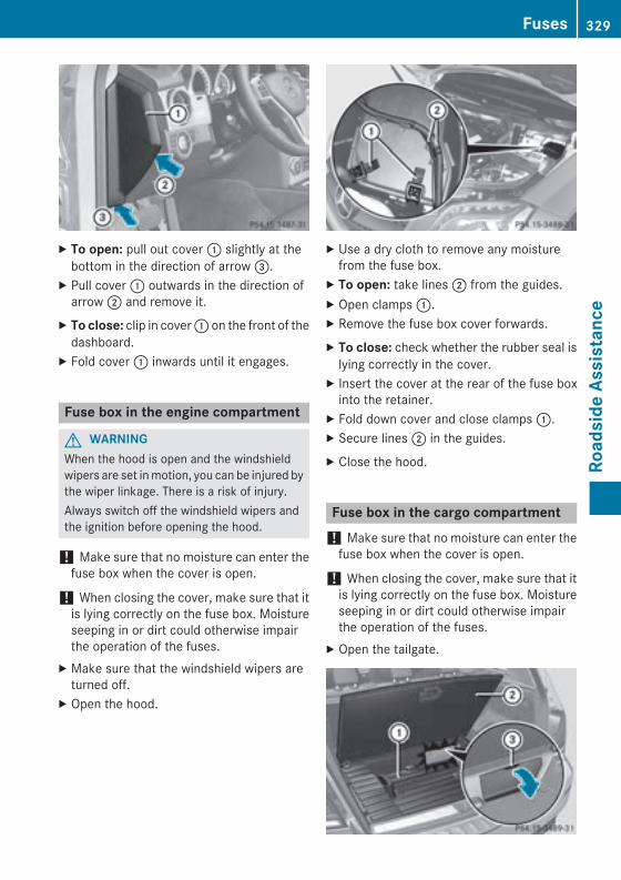
X To open: pull out cover : slightly at thebottom in the direction of arrow =.
X Pull cover : outwards in the direction ofarrow ; and remove it.
X To close: clip in cover : on the front of thedashboard.
X Fold cover : inwards until it engages.
Fuse box in the engine compartment
G WARNINGWhen the hood is open and the windshieldwipers are set in motion, you can be injured bythe wiper linkage. There is a risk of injury.Always switch off the windshield wipers andthe ignition before opening the hood.
! Make sure that no moisture can enter thefuse box when the cover is open.
! When closing the cover, make sure that itis lying correctly on the fuse box. Moistureseeping in or dirt could otherwise impairthe operation of the fuses.
X Make sure that the windshield wipers areturned off.
X Open the hood.
X Use a dry cloth to remove any moisturefrom the fuse box.
X To open: take lines ; from the guides.X Open clamps :.X Remove the fuse box cover forwards.X To close: check whether the rubber seal is
lying correctly in the cover.X Insert the cover at the rear of the fuse box
into the retainer.X Fold down cover and close clamps :.X Secure lines ; in the guides.X Close the hood.
Fuse box in the cargo compartment! Make sure that no moisture can enter the
fuse box when the cover is open.
! When closing the cover, make sure that itis lying correctly on the fuse box. Moistureseeping in or dirt could otherwise impairthe operation of the fuses.
X Open the tailgate.
Fuses 329
Road
side
Ass
ista
nce
Z

X To open: lift up cargo compartmentfloor ;(Y page 281).
X Remove stowage compartment :.X Open cover = of fuse box downwards.
330 FusesRo
adsi
de A
ssis
tanc
e

Useful information ............................ 332Important safety notes ..................... 332Operation ........................................... 332Winter operation ............................... 334Tire pressure ..................................... 336Loading the vehicle .......................... 343Maximum load rating ....................... 346Uniform Tire Quality GradingStandards .......................................... 347Tire labeling ....................................... 348Definition of terms for tires andloading ............................................... 352Changing a wheel .............................. 355Mounting a wheel ............................. 356Wheel and tire combinations ........... 360Emergency spare wheel ................... 366
331
Whe
els
and
tires
Useful information
i This Operator's Manual describes allmodels and all standard and optional equip-ment of your vehicle available at the time ofpublication of the Operator's Manual.Country-specific differences are possible.Please note that your vehicle may not beequipped with all features described. Thisalso applies to safety-related systems andfunctions.
i Read the information on qualified special-ist workshops (Y page 27).
Important safety notes
G WARNINGIf wheels and tires of the wrong size are used,the wheel brakes or suspension componentsmay be damaged. There is a risk of an acci-dent.Always replace wheels and tires with thosethat fulfill the specifications of the originalpart.When replacing wheels, make sure to use thecorrect:RdesignationRmodelWhen replacing tires, make sure to use thecorrect:RdesignationRmanufacturerRmodel
G WARNINGA flat tire severely impairs the driving, steer-ing and braking characteristics of the vehicle.There is a risk of accident.Tires without run-flat characteristics:Rdo not drive with a flat tire.Rimmediately replace the flat tire with your
emergency spare wheel or spare wheel, orconsult a qualified specialist workshop.
Tires with run-flat characteristics:Rpay attention to the information and warn-
ing notices on MOExtended tires (tires withrun-flat characteristics).
Accessories that are not approved for yourvehicle by Mercedes-Benz or are not beingused correctly can impair the operatingsafety.Before purchasing and using non-approvedaccessories, visit a qualified specialist work-shop and inquire about:RsuitabilityRlegal stipulationsRfactory recommendationsInformation on the sizes and types of wheelsand tires for your vehicle can be found in the"Wheel/tire combination" section(Y page 360).Information on tire pressure can be found:Ron the vehicle's Tire and Loading Informa-
tion placard on the B-pillar (Y page 343)Ron the tire pressure label on the fuel filler
flap (Y page 164)Runder "Tire pressure" (Y page 336)
Operation
Information on drivingRCheck the tire pressure when the vehicle is
heavily laden and adjust prior to a trip.RWhile driving, pay attention to vibrations,
noises and unusual handling characteris-tics, e.g. pulling to one side. This may indi-cate that the wheels or tires are damaged.If you suspect that a tire is defective,reduce your speed immediately. Stop thevehicle as soon as possible to check thewheels and tires for damage. Hidden tiredamage could also be causing the unusualhandling characteristics. If you find no
332 OperationW
heel
s an
d tir
es
signs of damage, have the tires and wheelschecked at a qualified specialist workshop.RWhen parking your vehicle, make sure that
the tires do not get deformed by the curb orother obstacles. If it is necessary to driveover curbs, speed humps or similar eleva-tions, try to do so slowly and at an obtuseangle. Otherwise, the tires, particularly thesidewalls, may be damaged.
Regular checking of wheels and tires
G WARNINGDamaged tires can cause tire inflation pres-sure loss. As a result, you could lose control ofyour vehicle. There is a risk of accident.Check the tires regularly for signs of damageand replace any damaged tires immediately.
RRegularly check the wheels and tires ofyour vehicle for damage at least once amonth, as well as after driving off-road oron rough roads. Damaged wheels cancause a loss of tire pressure. Pay particularattention to damage such as:- cuts in the tires- punctures- tears in the tires- bulges on tires- deformation or severe corrosion on
wheelsRRegularly check the tire tread depth and
the condition of the tread across the wholewidth of the tire (Y page 333). If necessary,turn the front wheels to full lock in order toinspect the inner side of the tire surface.RAll wheels must have a valve cap to protect
the valve against dirt and moisture. Do notmount anything onto the valve other thanthe standard valve cap or other valve capsapproved by Mercedes-Benz for your vehi-cle. Do not use any other valve caps or sys-
tems, e.g. tire pressure monitoring sys-tems.RRegularly check the pressure of all the tires
particularly prior to long trips. Adjust thetire pressure as necessary (Y page 336).
Observe the notes on the emergency sparewheel (Y page 366).The service life of tires depends, among otherthings, on the following factors:RDriving styleRTire pressureRDistance covered
Notes on tire tread
G WARNINGInsufficient tire tread will reduce tire traction.The tire is no longer able to dissipate water.This means that on wet road surfaces, the riskof hydroplaning increases, in particular wherespeed is not adapted to suit the driving con-ditions. There is a risk of accident.If the tire pressure is too high or too low, tiresmay exhibit different levels of wear at differ-ent locations on the tire tread. Thus, youshould regularly check the tread depth andthe condition of the tread across the entirewidth of all tires.Minimum tire tread depth for:RSummer tires: â in (3 mm)RM+S tires: ã in (4 mm)For safety reasons, replace the tires beforethe legally prescribed limit for the minimumtire tread depth is reached.
Operation 333
Whe
els
and
tires
Z
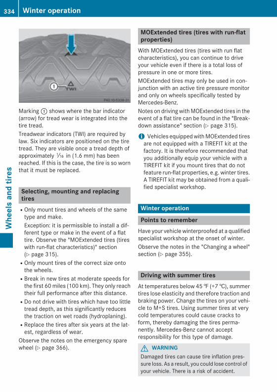
Marking : shows where the bar indicator(arrow) for tread wear is integrated into thetire tread.Treadwear indicators (TWI) are required bylaw. Six indicators are positioned on the tiretread. They are visible once a tread depth ofapproximately á in (1.6 mm) has beenreached. If this is the case, the tire is so wornthat it must be replaced.
Selecting, mounting and replacingtiresROnly mount tires and wheels of the same
type and make.Exception: it is permissible to install a dif-ferent type or make in the event of a flattire. Observe the "MOExtended tires (tireswith run-flat characteristics)" section(Y page 315).ROnly mount tires of the correct size onto
the wheels.RBreak in new tires at moderate speeds for
the first 60 miles (100 km). They only reachtheir full performance after this distance.RDo not drive with tires which have too little
tread depth, as this significantly reducesthe traction on wet roads (hydroplaning).RReplace the tires after six years at the lat-
est, regardless of wear.Observe the notes on the emergency sparewheel (Y page 366).
MOExtended tires (tires with run-flatproperties)
With MOExtended tires (tires with run flatcharacteristics), you can continue to driveyour vehicle even if there is a total loss ofpressure in one or more tires.MOExtended tires may only be used in con-junction with an active tire pressure monitorand only on wheels specifically tested byMercedes-Benz.Notes on driving with MOExtended tires in theevent of a flat tire can be found in the "Break-down assistance" section (Y page 315).
i Vehicles equipped with MOExtended tiresare not equipped with a TIREFIT kit at thefactory. It is therefore recommended thatyou additionally equip your vehicle with aTIREFIT kit if you mount tires that do notfeature run-flat properties, e.g. winter tires.A TIREFIT kit may be obtained from a quali-fied specialist workshop.
Winter operation
Points to rememberHave your vehicle winterproofed at a qualifiedspecialist workshop at the onset of winter.Observe the notes in the "Changing a wheel"section (Y page 355).
Driving with summer tiresAt temperatures below 45 ‡ (+7 †), summertires lose elasticity and therefore traction andbraking power. Change the tires on your vehi-cle to M+S tires. Using summer tires at verycold temperatures could cause cracks toform, thereby damaging the tires perma-nently. Mercedes-Benz cannot acceptresponsibility for this type of damage.
G WARNINGDamaged tires can cause tire inflation pres-sure loss. As a result, you could lose control ofyour vehicle. There is a risk of accident.
334 Winter operationW
heel
s an
d tir
es

Check the tires regularly for signs of damageand replace any damaged tires immediately.
M+S tires
G WARNINGM+S tires with a tire tread depth of less thanã in (4 mm) are not suitable for use in winterand do not provide sufficient traction. There isa risk of an accident.M+S tires with a tread depth of less than ã in(4 mm) must be replaced immediately.
At temperatures below 45 ‡ (+7 †), use win-ter tires or all-season tires. Both types of tireare identified by the M+S marking.Only winter tires bearing the i snowflakesymbol in addition to the M+S marking pro-vide the best possible grip in wintry road con-ditions. Only these tires will allow drivingsafety systems such as ABS and ESP® tofunction optimally in winter. These tires havebeen developed specifically for driving insnow.Use M+S tires of the same make and tread onall wheels to maintain safe handling charac-teristics.Always observe the maximum permissiblespeed specified for the M+S tires you havemounted.When you have mounted M+S tires:X Check the tire pressures (Y page 339).X Restart the tire pressure monitor
(Y page 339).For more information on driving with theemergency spare wheel, see (Y page 366).
Snow chains
G WARNINGIf snow chains are installed to the frontwheels, they may drag against the vehiclebody or chassis components. This could
cause damage to the vehicle or the tires.There is a risk of an accident.To avoid hazardous situations:Rnever install snow chains to the front
wheelsRalways install snow chains in pairs to the
rear wheels.
! On some tire sizes there is not enoughspace for snow chains. To avoid damage tothe vehicle or tires, observe the "Wheel andtire combinations" section under "Tires andwheels".
! Vehicles with steel wheels: if youmount snow chains on steel wheels, youmay damage the hub caps. Remove the hubcaps from the relevant wheels beforemounting the snow chains.
For safety reasons, Mercedes-Benz recom-mends that you only use snow chains thathave been specially approved for your vehicleby Mercedes-Benz, or are of a correspondingstandard of quality. For more information,please contact a qualified specialist work-shop.If you intend to mount snow chains, pleasebear the following points in mind:RSnow chains may not be mounted on all
wheel/tire combinations. Permissiblewheel-tire combinations (Y page 360).ROnly use snow chains when driving on
roads completely covered by snow.Remove the snow chains as soon as possi-ble when you come to a road that is notsnow-covered.RLocal regulations may restrict the use of
snow chains. Observe the appropriate reg-ulations if you wish to mount snow chains.RDo not exceed the maximum permissible
speed of 30 mph (50 km/h).
i You may wish to deactivate ESP®
(Y page 71) when pulling away with snowchains installed. You can thereby allow thewheels to spin in a controlled manner, ach-
Winter operation 335
Whe
els
and
tires
Z

ieving an increased driving force (cuttingaction).
For more information on driving with theemergency spare wheel, see (Y page 366).
Tire pressure
Tire pressure specificationsOperation with a trailer: the applicablevalue for the rear tires is the maximum tirepressure value stated in the table inside thefuel filler flap.Use a suitable pressure gauge to check thetire pressure. The outer appearance of a tiredoes not permit any reliable conclusion aboutthe tire pressure. You can also check the tirepressure using the on-board computer.
G WARNINGUnderinflated or overinflated tires pose thefollowing risks:Rthe tires may burst, especially as the load
and vehicle speed increase.Rthe tires may wear excessively and/or
unevenly, which may greatly impair tiretraction.Rthe driving characteristics, as well as steer-
ing and braking, may be greatly impaired.There is a risk of an accident.Follow recommended tire inflation pressuresand check the pressure of all the tires includ-ing the spare wheel:Rmonthly, at leastRif the load changesRbefore beginning a long journeyRunder different operating conditions, e.g.
off-road drivingIf necessary, correct the tire pressure.
The recommended tire pressures for the tiresmounted at the factory can be found on thelabels described here.
1.) Tire and Loading Information placardon the B-pillar on the driver's side of the vehi-cle (Y page 343).The Tire and Loading Information placard con-tains the recommended tire pressures forcold tires on a fully loaded vehicle and for themaximum permissible vehicle speed.
i The specifications given on the followingTire and Loading Information placard areexamples. Tire pressure specifications arevehicle-specific and may deviate from thedata shown here. The tire pressures appli-cable to your vehicle can be found on theTire and Loading Information placard onyour vehicle.
: Recommended tire pressuresOption 2) Tire pressure table on the inside ofthe fuel filler flap.The tire pressure table contains the recom-mended pressures for cold tires for variousoperating conditions, i.e. differing load andspeed conditions.
i Specifications shown in the examples oftire pressure tables are for illustration pur-poses only. Tire pressure specifications arevehicle-specific and may deviate from thedata shown here. Tire pressure specifica-tions applicable to your vehicle are locatedin your vehicle's tire pressure table.
336 Tire pressureW
heel
s an
d tir
es
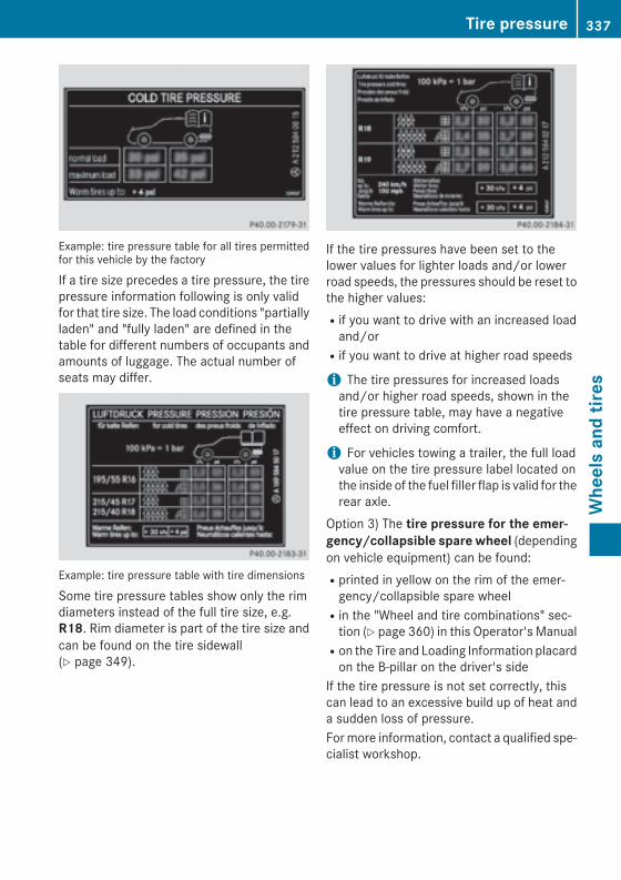
Example: tire pressure table for all tires permittedfor this vehicle by the factory
If a tire size precedes a tire pressure, the tirepressure information following is only validfor that tire size. The load conditions "partiallyladen" and "fully laden" are defined in thetable for different numbers of occupants andamounts of luggage. The actual number ofseats may differ.
Example: tire pressure table with tire dimensions
Some tire pressure tables show only the rimdiameters instead of the full tire size, e.g.R18. Rim diameter is part of the tire size andcan be found on the tire sidewall(Y page 349).
If the tire pressures have been set to thelower values for lighter loads and/or lowerroad speeds, the pressures should be reset tothe higher values:Rif you want to drive with an increased load
and/orRif you want to drive at higher road speeds
i The tire pressures for increased loadsand/or higher road speeds, shown in thetire pressure table, may have a negativeeffect on driving comfort.
i For vehicles towing a trailer, the full loadvalue on the tire pressure label located onthe inside of the fuel filler flap is valid for therear axle.
Option 3) The tire pressure for the emer-gency/collapsible spare wheel (dependingon vehicle equipment) can be found:Rprinted in yellow on the rim of the emer-
gency/collapsible spare wheelRin the "Wheel and tire combinations" sec-
tion (Y page 360) in this Operator's ManualRon the Tire and Loading Information placard
on the B-pillar on the driver's sideIf the tire pressure is not set correctly, thiscan lead to an excessive build up of heat anda sudden loss of pressure.For more information, contact a qualified spe-cialist workshop.
Tire pressure 337
Whe
els
and
tires
Z
Important notes on tire pressure
G WARNINGIf the tire pressure drops repeatedly, thewheel, valve or tire may be damaged. Tirepressure that is too low may result in a tireblow-out. There is a risk of an accident.RCheck the tire for foreign objects.RCheck whether the wheel is losing air or the
valve is leaking.If you are unable to rectify the damage, con-tact a qualified specialist workshop.
G WARNINGIf you fit unsuitable accessories onto tirevalves, the tire valves may be overloaded andmalfunction, which can cause tire pressureloss. Due to their design, retrofitted tire pres-sure monitors keep the tire valve open. Thiscan also result in tire pressure loss. There is arisk of an accident.Only screw the standard valve cap or othervalve caps approved by Mercedes-Benz foryour vehicle onto the tire valve.
To test tire pressure, use a suitable tire pres-sure gauge. The outer appearance of a tiredoes not permit any reliable conclusion aboutthe tire pressure. On vehicles equipped withthe electronic tire pressure monitor, the tirepressure can be checked in the on-boardcomputer.The tire temperature and pressure increasewhen the vehicle is in motion. This is depend-ent on the driving speed and the load.Therefore, you should only correct tire pres-sures when the tires are cold.The tires are cold:Rif the vehicle has been parked without
direct sunlight on the tires for at least threehours andRif the vehicle has not been driven further
than 1 mile (1.6 km)The tire temperature changes depending onthe outside temperature, the vehicle speedand the tire load. If the tire temperature
changes by 18 ‡ (10 †), the tire pressurechanges by approximately 10 kPa (0.1 bar/1.5 psi). Take this into account when check-ing the pressure of warm tires. Only correctthe tire pressure if it is too low for the currentoperating conditions. If you check the tirepressure when the tires are warm, the result-ing value will be higher than if the tires werecold. This is normal. Do not reduce the tirepressure to the value specified for cold tires.The tire pressure would otherwise be too low.Observe the recommended tire pressures forcold tires:Ron the Tire and Loading Information placard
on the B-pillar on the driver's sideRin the tire pressure table on the inside of the
fuel filler flapRprinted in yellow on the rim of the emer-
gency/collapsible spare wheel (dependingon vehicle equipment)
Underinflated or overinflated tires
Underinflation
G WARNINGTires with pressure that is too low can over-heat and burst as a consequence. In addition,they also suffer from excessive and/or irreg-ular wear, which can severely impair the brak-ing properties and the driving characteristics.There is a risk of an accident.Avoid tire pressures that are too low in all thetires, including the spare wheel.
Underinflated tires may:Rwear quickly and unevenlyRhave an adverse effect on fuel consumptionRoverheat, leading to tire defectsRhave an adverse effect on handling charac-
teristics
338 Tire pressureW
heel
s an
d tir
es
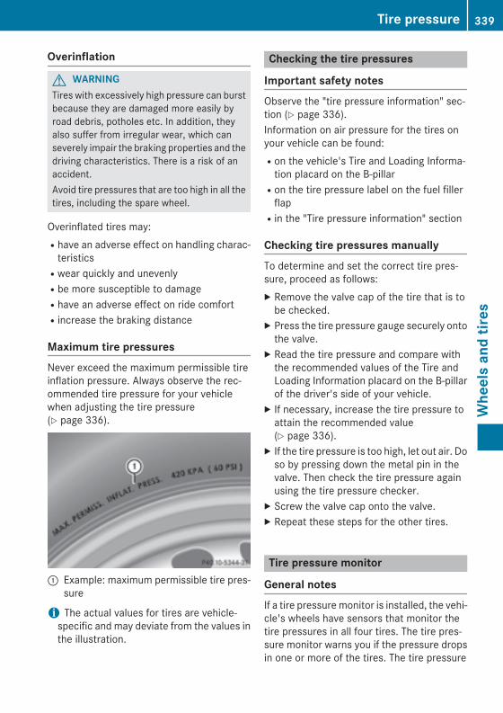
Overinflation
G WARNINGTires with excessively high pressure can burstbecause they are damaged more easily byroad debris, potholes etc. In addition, theyalso suffer from irregular wear, which canseverely impair the braking properties and thedriving characteristics. There is a risk of anaccident.Avoid tire pressures that are too high in all thetires, including the spare wheel.
Overinflated tires may:Rhave an adverse effect on handling charac-
teristicsRwear quickly and unevenlyRbe more susceptible to damageRhave an adverse effect on ride comfortRincrease the braking distance
Maximum tire pressuresNever exceed the maximum permissible tireinflation pressure. Always observe the rec-ommended tire pressure for your vehiclewhen adjusting the tire pressure(Y page 336).
: Example: maximum permissible tire pres-sure
i The actual values for tires are vehicle-specific and may deviate from the values inthe illustration.
Checking the tire pressures
Important safety notesObserve the "tire pressure information" sec-tion (Y page 336).Information on air pressure for the tires onyour vehicle can be found:Ron the vehicle's Tire and Loading Informa-
tion placard on the B-pillarRon the tire pressure label on the fuel filler
flapRin the "Tire pressure information" section
Checking tire pressures manuallyTo determine and set the correct tire pres-sure, proceed as follows:X Remove the valve cap of the tire that is to
be checked.X Press the tire pressure gauge securely onto
the valve.X Read the tire pressure and compare with
the recommended values of the Tire andLoading Information placard on the B-pillarof the driver's side of your vehicle.
X If necessary, increase the tire pressure toattain the recommended value(Y page 336).
X If the tire pressure is too high, let out air. Doso by pressing down the metal pin in thevalve. Then check the tire pressure againusing the tire pressure checker.
X Screw the valve cap onto the valve.X Repeat these steps for the other tires.
Tire pressure monitor
General notesIf a tire pressure monitor is installed, the vehi-cle's wheels have sensors that monitor thetire pressures in all four tires. The tire pres-sure monitor warns you if the pressure dropsin one or more of the tires. The tire pressure
Tire pressure 339
Whe
els
and
tires
Z

monitor only functions if the correspondingsensors are installed on all wheels.Information on tire pressures is displayed inthe multifunction display. After a few minutesof driving, the current tire pressure of eachtire is shown in the Service menu of the mul-tifunction display.
Example: current tire pressure display
For information on the message display, referto the "Checking the tire pressure electroni-cally" section (Y page 341).
Important safety notes
G WARNINGEach tire, including the spare (if provided),should be checked at least once a monthwhen cold and inflated to the pressure rec-ommended by the vehicle manufacturer onthe Tire and Loading Information placard onthe driver's door B-pillar or the tire pressurelabel on the inside of the fuel filler flap. If yourvehicle has tires of a different size than thesize indicated on the Tire and Loading Infor-mation placard or the tire pressure label, youshould determine the proper tire pressure forthose tires.As an added safety feature, your vehicle hasbeen equipped with a tire pressure monitoringsystem (TPMS) that illuminates a low tire pres-sure telltale when one or more of your tiresare significantly underinflated. Accordingly,when the low tire pressure telltale illuminates,you should stop and check your tires as soonas possible, and inflate them to the properpressure. Driving on a significantly underin-flated tire causes the tire to overheat and canlead to tire failure. Underinflation alsoreduces fuel efficiency and tire tread life, and
may affect the vehicle's handling and stop-ping ability.Please note that the TPMS is not a substitutefor proper tire maintenance, and it is the driv-er's responsibility to maintain correct tirepressure, even if underinflation has notreached the level to trigger illumination of theTPMS low tire pressure telltale.Your vehicle has also been equipped with aTPMS malfunction indicator to indicate if thesystem is not operating properly. The TPMSmalfunction indicator is combined with thelow tire pressure telltale. When the systemdetects a malfunction, the warning lamp willflash for approximately a minute and thenremain continuously illuminated. Thissequence will be repeated every time the vehi-cle is started as long as the malfunctionexists.When the malfunction indicator is illuminated,the system may not be able to detect or signallow tire pressure as intended. TPMS malfunc-tions may occur for a variety of reasons,including the installation of incompatiblereplacement or alternate tires or wheels onthe vehicle that prevent the TPMS from func-tioning properly. Always check the TPMS mal-function telltale after replacing one or moretires or wheels on your vehicle to ensure thatthe replacement or alternate tires and wheelsallow the TPMS to continue to function prop-erly.
It is the driver's responsibility to set the tirepressure to that recommended for cold tireswhich is suitable for the operating situation(Y page 336). Note that the correct tire pres-sure for the current operating situation mustfirst be taught-in to the tire pressure monitor.If there is a substantial loss of pressure, thewarning threshold for the warning message isaligned to the reference values taught-in.Restart the tire pressure monitor after adjust-ing the pressure of the cold tires(Y page 342). The current pressures aresaved as new reference values. As a result, a
340 Tire pressureW
heel
s an
d tir
es
warning message will appear if the tire pres-sure drops significantly.The tire pressure monitor does not warn youof an incorrectly set tire pressure. Observethe notes on the recommended tire pressure(Y page 336).The tire pressure monitor is not able to warnyou of a sudden loss of pressure, e.g. if thetire is penetrated by a foreign object. In theevent of a sudden loss of pressure, bring thevehicle to a halt by braking carefully. Avoidabrupt steering maneuvers.The tire pressure monitor has a yellow warn-ing lamp in the instrument cluster for indicat-ing a pressure loss or malfunction. Whetherthe warning lamp flashes or lights up indi-cates whether a tire pressure is too low or thetire pressure monitor is malfunctioning:Rif the warning lamp is lit continuously, the
tire pressure on one or more tires is signif-icantly too low. The tire pressure monitor isnot malfunctioning.Rif the warning lamp flashes for around a
minute and then remains lit constantly, thetire pressure monitor is malfunctioning.
i In addition to the warning lamp, a mes-sage appears in the multifunction display.Observe the information on display mes-sages (Y page 255).
It may take up to ten minutes for a malfunc-tion of the tire pressure monitor to be indica-ted. A malfunction will be indicated by the tirepressure warning lamp flashing for approx-imately one minute and then remaining lit.When the malfunction has been rectified, thetire pressure warning lamp goes out after afew minutes of driving.The tire pressure values indicated by the on-board computer may differ from those meas-ured at a gas station with a pressure gauge.The tire pressures shown by the on-boardcomputer refer to those measured at sealevel. At high altitudes, the tire pressure val-ues indicated by a pressure gauge are higherthan those shown by the on-board computer.In this case, do not reduce the tire pressures.
The operation of the tire pressure monitor canbe affected by interference from radio trans-mitting equipment (e.g. radio headphones,two-way radios) that may be being operatedin or near the vehicle.
Checking the tire pressure electroni-callyX Make sure that the SmartKey is in position
2 in the ignition lock (Y page 149).X Press the = or ; button on the steer-
ing wheel to select the Service menu.X Press the 9 or : button to selectTire Pressure.
X Press the a button.The current tire pressure of each tire isshown in the multifunction display.
If the vehicle has been parked for over20 minutes, the Tire pressures will be displayed after driving a few minutes message appears.After a teach-in process, the tire pressuremonitor automatically detects new wheels ornew sensors. As long as a clear allocation ofthe tire pressure value to the individualwheels is not possible, the Tire Pressure Monitor Active display message is showninstead of the tire pressure display. The tirepressures are already being monitored.
i If an emergency spare wheel is mounted,the system may continue to show the tirepressure of the wheel that has beenremoved for a few minutes. If this occurs,note that the value displayed for the posi-tion where the spare wheel is mounted isnot the same as the current tire pressure ofthe emergency spare wheel.
Tire pressure 341
Whe
els
and
tires
Z
Tire pressure monitor warning mes-sagesIf the tire pressure monitor detects a pressureloss in one or more tires, a warning messageis shown in the multifunction display and theyellow tire pressure monitor warning lampcomes on.RIf the Correct Tire Pressure message
appears in the multifunction display, thetire pressure in at least one tire is too lowand must be corrected at the next oppor-tunity.RIf the Check Tires message appears in the
multifunction display, the tire pressure inone or more tires has dropped significantlyand the tires must be checked.RIf the Warning Tire Malfunction mes-
sage appears in the multifunction display,the tire pressure in one or more tires hasdropped suddenly and the tires must bechecked.
Observe the instructions and safety notes inthe display messages in the "Tires" section(Y page 255).
i If the wheel positions on the vehicle arerotated, the tire pressures may be dis-played for the wrong positions for a shorttime. This is rectified after a few minutes ofdriving, and the tire pressures are displayedfor the correct positions.
Restarting the tire pressure monitorWhen you restart the tire pressure monitor, allexisting warning messages are deleted andthe warning lamps go out. The monitor usesthe currently set tire pressures as the refer-ence values for monitoring. In most cases, thetire pressure monitor will automaticallydetect the new reference values after youhave changed the tire pressure. However, youcan also define reference values manually asdescribed here. The tire pressure monitorthen monitors the new tire pressure values.X Set the tire pressure to the value recom-
mended for the corresponding driving sit-
uation on the Tire and Loading Informationplacard on the driver's sideB-pillar (Y page 336).Additional tire pressure values for differentloads can also be found on the tire pressuretable on the inside of the fuel filler flap(Y page 336).
X Make sure that the tire pressure is correcton all four wheels.
X Make sure that the SmartKey is in position2 in the ignition lock.
X Press the = or ; button on the steer-ing wheel to select the Service menu.
X Press the 9 or : button to selectTire Pressure.
X Press the a button.The multifunction display shows the cur-rent tire pressure for the individual tires orthe Tire pressures will be dis‐played after driving a few minutesmessage.
X Press the : button.The Use Current Pressures as New Reference Values message appears inthe multifunction display.
If you wish to confirm the restart:X Press the a button.
The Tire Press. Monitor Restartedmessage appears in the multifunction dis-play.After driving for a few minutes, the systemchecks whether the current tire pressuresare within the specified range. The new tirepressures are then accepted as referencevalues and monitored.
If you wish to cancel the restart:X Press the % button.
The tire pressure values stored at the lastrestart will continue to be monitored.
342 Tire pressureW
heel
s an
d tir
es
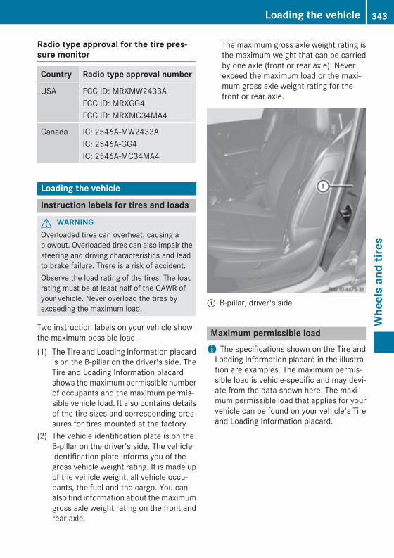
Radio type approval for the tire pres-sure monitor
Country Radio type approval number
USA FCC ID: MRXMW2433AFCC ID: MRXGG4FCC ID: MRXMC34MA4
Canada IC: 2546A-MW2433AIC: 2546A-GG4IC: 2546A-MC34MA4
Loading the vehicle
Instruction labels for tires and loads
G WARNINGOverloaded tires can overheat, causing ablowout. Overloaded tires can also impair thesteering and driving characteristics and leadto brake failure. There is a risk of accident.Observe the load rating of the tires. The loadrating must be at least half of the GAWR ofyour vehicle. Never overload the tires byexceeding the maximum load.
Two instruction labels on your vehicle showthe maximum possible load.(1) The Tire and Loading Information placard
is on the B-pillar on the driver's side. TheTire and Loading Information placardshows the maximum permissible numberof occupants and the maximum permis-sible vehicle load. It also contains detailsof the tire sizes and corresponding pres-sures for tires mounted at the factory.
(2) The vehicle identification plate is on theB-pillar on the driver's side. The vehicleidentification plate informs you of thegross vehicle weight rating. It is made upof the vehicle weight, all vehicle occu-pants, the fuel and the cargo. You canalso find information about the maximumgross axle weight rating on the front andrear axle.
The maximum gross axle weight rating isthe maximum weight that can be carriedby one axle (front or rear axle). Neverexceed the maximum load or the maxi-mum gross axle weight rating for thefront or rear axle.
: B-pillar, driver's side
Maximum permissible loadi The specifications shown on the Tire and
Loading Information placard in the illustra-tion are examples. The maximum permis-sible load is vehicle-specific and may devi-ate from the data shown here. The maxi-mum permissible load that applies for yourvehicle can be found on your vehicle's Tireand Loading Information placard.
Loading the vehicle 343
Whe
els
and
tires
Z
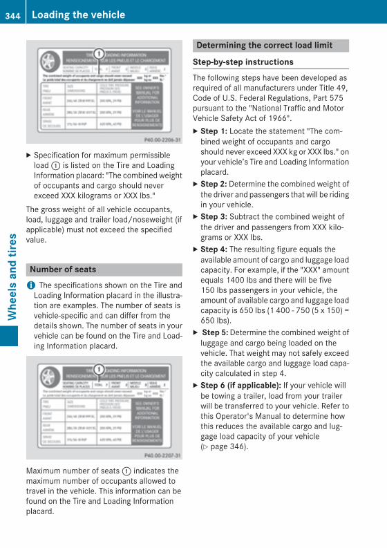
X Specification for maximum permissibleload : is listed on the Tire and LoadingInformation placard: "The combined weightof occupants and cargo should neverexceed XXX kilograms or XXX lbs."
The gross weight of all vehicle occupants,load, luggage and trailer load/noseweight (ifapplicable) must not exceed the specifiedvalue.
Number of seatsi The specifications shown on the Tire and
Loading Information placard in the illustra-tion are examples. The number of seats isvehicle-specific and can differ from thedetails shown. The number of seats in yourvehicle can be found on the Tire and Load-ing Information placard.
Maximum number of seats : indicates themaximum number of occupants allowed totravel in the vehicle. This information can befound on the Tire and Loading Informationplacard.
Determining the correct load limit
Step-by-step instructionsThe following steps have been developed asrequired of all manufacturers under Title 49,Code of U.S. Federal Regulations, Part 575pursuant to the "National Traffic and MotorVehicle Safety Act of 1966".X Step 1: Locate the statement "The com-
bined weight of occupants and cargoshould never exceed XXX kg or XXX lbs." onyour vehicle’s Tire and Loading Informationplacard.
X Step 2: Determine the combined weight ofthe driver and passengers that will be ridingin your vehicle.
X Step 3: Subtract the combined weight ofthe driver and passengers from XXX kilo-grams or XXX lbs.
X Step 4: The resulting figure equals theavailable amount of cargo and luggage loadcapacity. For example, if the "XXX" amountequals 1400 lbs and there will be five150 lbs passengers in your vehicle, theamount of available cargo and luggage loadcapacity is 650 lbs (1 400 - 750 (5 x 150) =650 lbs).
X Step 5: Determine the combined weight ofluggage and cargo being loaded on thevehicle. That weight may not safely exceedthe available cargo and luggage load capa-city calculated in step 4.
X Step 6 (if applicable): If your vehicle willbe towing a trailer, load from your trailerwill be transferred to your vehicle. Refer tothis Operator's Manual to determine howthis reduces the available cargo and lug-gage load capacity of your vehicle(Y page 346).
344 Loading the vehicleW
heel
s an
d tir
es
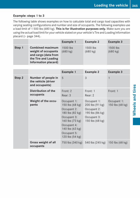
Example: steps 1 to 3The following table shows examples on how to calculate total and cargo load capacities withvarying seating configurations and number and size of occupants. The following examples usea load limit of 1 500 lbs (680 kg). This is for illustration purposes only. Make sure you areusing the actual load limit for your vehicle stated on your vehicle's Tire and Loading Informationplacard (Y page 344).
Example 1 Example 2 Example 3
Step 1 Combined maximum weight of occupants and cargo (data from the Tire and Loading Information placard)
1500 lbs(680 kg)
1500 lbs(680 kg)
1500 lbs(680 kg)
Example 1 Example 2 Example 3
Step 2 Number of people in the vehicle (driver and occupants)
5 3 1
Distribution of the occupants
Front: 2Rear: 3
Front: 1Rear: 2
Front: 1
Weight of the occu-pants
Occupant 1:150 lbs (68 kg)Occupant 2:180 lbs (82 kg)Occupant 3:160 lbs (73 kg)Occupant 4:140 lbs (63 kg)Occupant 5:120 lbs (54 kg)
Occupant 1:200 lbs (91 kg)Occupant 2:190 lbs (86 kg)Occupant 3:150 lbs (68 kg)
Occupant 1:150 lbs (68 kg)
Gross weight of all occupants
750 lbs (340 kg) 540 lbs (245 kg) 150 lbs (68 kg)
Loading the vehicle 345
Whe
els
and
tires
Z
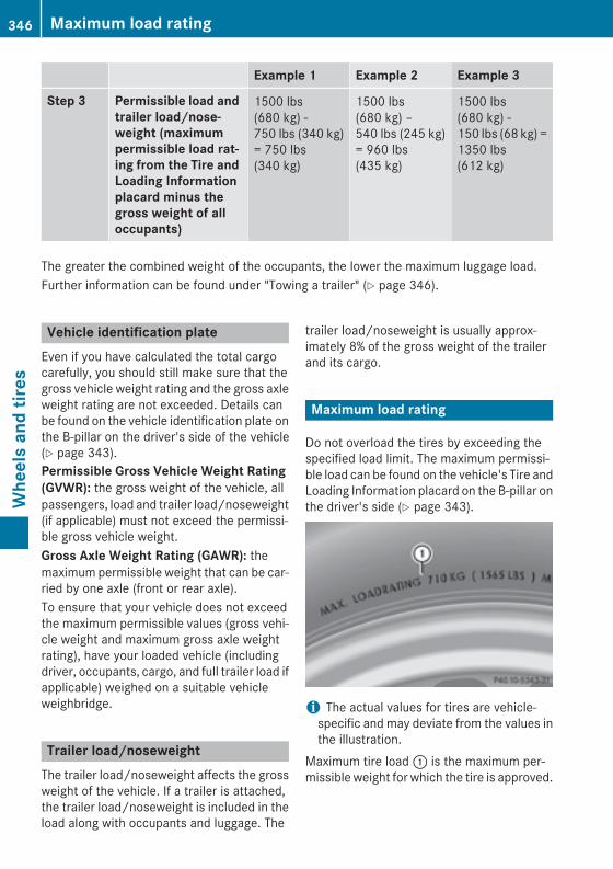
Example 1 Example 2 Example 3
Step 3 Permissible load and trailer load/nose-weight (maximum permissible load rat-ing from the Tire and Loading Information placard minus the gross weight of all occupants)
1500 lbs(680 kg) -750 lbs (340 kg)= 750 lbs(340 kg)
1500 lbs(680 kg) –540 lbs (245 kg)= 960 lbs(435 kg)
1500 lbs(680 kg) -150 lbs (68 kg) =1350 lbs(612 kg)
The greater the combined weight of the occupants, the lower the maximum luggage load.Further information can be found under "Towing a trailer" (Y page 346).
Vehicle identification plateEven if you have calculated the total cargocarefully, you should still make sure that thegross vehicle weight rating and the gross axleweight rating are not exceeded. Details canbe found on the vehicle identification plate onthe B-pillar on the driver's side of the vehicle(Y page 343).Permissible Gross Vehicle Weight Rating (GVWR): the gross weight of the vehicle, allpassengers, load and trailer load/noseweight(if applicable) must not exceed the permissi-ble gross vehicle weight.Gross Axle Weight Rating (GAWR): themaximum permissible weight that can be car-ried by one axle (front or rear axle).To ensure that your vehicle does not exceedthe maximum permissible values (gross vehi-cle weight and maximum gross axle weightrating), have your loaded vehicle (includingdriver, occupants, cargo, and full trailer load ifapplicable) weighed on a suitable vehicleweighbridge.
Trailer load/noseweightThe trailer load/noseweight affects the grossweight of the vehicle. If a trailer is attached,the trailer load/noseweight is included in theload along with occupants and luggage. The
trailer load/noseweight is usually approx-imately 8% of the gross weight of the trailerand its cargo.
Maximum load rating
Do not overload the tires by exceeding thespecified load limit. The maximum permissi-ble load can be found on the vehicle's Tire andLoading Information placard on the B-pillar onthe driver's side (Y page 343).
i The actual values for tires are vehicle-specific and may deviate from the values inthe illustration.
Maximum tire load : is the maximum per-missible weight for which the tire is approved.
346 Maximum load ratingW
heel
s an
d tir
es
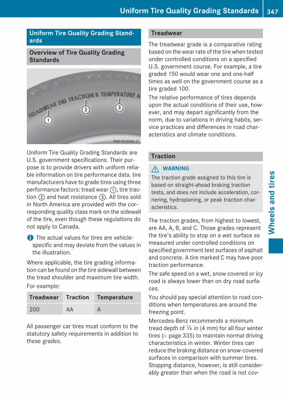
Uniform Tire Quality Grading Stand-ards
Overview of Tire Quality GradingStandards
Uniform Tire Quality Grading Standards areU.S. government specifications. Their pur-pose is to provide drivers with uniform relia-ble information on tire performance data. tiremanufacturers have to grade tires using threeperformance factors: tread wear :, tire trac-tion ; and heat resistance =. All tires soldin North America are provided with the cor-responding quality class mark on the sidewallof the tire, even though these regulations donot apply to Canada.
i The actual values for tires are vehicle-specific and may deviate from the values inthe illustration.
Where applicable, the tire grading informa-tion can be found on the tire sidewall betweenthe tread shoulder and maximum tire width.For example:
Treadwear Traction Temperature
200 AA A
All passenger car tires must conform to thestatutory safety requirements in addition tothese grades.
TreadwearThe treadwear grade is a comparative ratingbased on the wear rate of the tire when testedunder controlled conditions on a specifiedU.S. government course. For example, a tiregraded 150 would wear one and one-halftimes as well on the government course as atire graded 100.The relative performance of tires dependsupon the actual conditions of their use, how-ever, and may depart significantly from thenorm, due to variations in driving habits, ser-vice practices and differences in road char-acteristics and climate conditions.
Traction
G WARNINGThe traction grade assigned to this tire isbased on straight-ahead braking tractiontests, and does not include acceleration, cor-nering, hydroplaning, or peak traction char-acteristics.
The traction grades, from highest to lowest,are AA, A, B, and C. Those grades representthe tire's ability to stop on a wet surface asmeasured under controlled conditions onspecified government test surfaces of asphaltand concrete. A tire marked C may have poortraction performance.The safe speed on a wet, snow covered or icyroad is always lower than on dry road surfa-ces.You should pay special attention to road con-ditions when temperatures are around thefreezing point.Mercedes-Benz recommends a minimumtread depth of ã in (4 mm) for all four wintertires (Y page 335) to maintain normal drivingcharacteristics in winter. Winter tires canreduce the braking distance on snow-coveredsurfaces in comparison with summer tires.Stopping distance, however, is still consider-ably greater than when the road is not cov-
Uniform Tire Quality Grading Standards 347
Whe
els
and
tires
Z
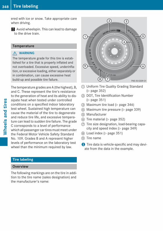
ered with ice or snow. Take appropriate carewhen driving.
! Avoid wheelspin. This can lead to damageto the drive train.
Temperature
G WARNINGThe temperature grade for this tire is estab-lished for a tire that is properly inflated andnot overloaded. Excessive speed, underinfla-tion, or excessive loading, either separately orin combination, can cause excessive heatbuild-up and possible tire failure.
The temperature grades are A (the highest), B,and C. These represent the tire's resistanceto the generation of heat and its ability to dis-sipate heat when tested under controlledconditions on a specified indoor laboratorytest wheel. Sustained high temperature cancause the material of the tire to degenerateand reduce tire life, and excessive tempera-ture can lead to sudden tire failure. The gradeC corresponds to a level of performancewhich all passenger car tires must meet underthe Federal Motor Vehicle Safety StandardNo. 109. Grades B and A represent higherlevels of performance on the laboratory testwheel than the minimum required by law.
Tire labeling
OverviewThe following markings are on the tire in addi-tion to the tire name (sales designation) andthe manufacturer's name:
: Uniform Tire Quality Grading Standard(Y page 352)
; DOT, Tire Identification Number(Y page 351)
= Maximum tire load (Y page 346)? Maximum tire pressure (Y page 339)A ManufacturerB Tire material (Y page 352)C Tire size designation, load-bearing capa-
city and speed index (Y page 349)D Load index (Y page 351)E Tire name
i Tire data is vehicle-specific and may devi-ate from the data in the example.
348 Tire labelingW
heel
s an
d tir
es
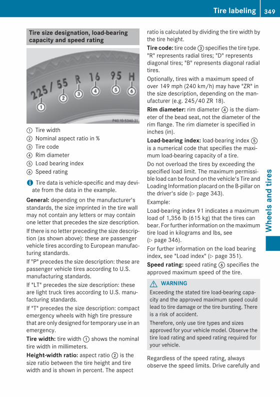
Tire size designation, load-bearingcapacity and speed rating
: Tire width; Nominal aspect ratio in %= Tire code? Rim diameterA Load bearing indexB Speed rating
i Tire data is vehicle-specific and may devi-ate from the data in the example.
General: depending on the manufacturer'sstandards, the size imprinted in the tire wallmay not contain any letters or may containone letter that precedes the size description.If there is no letter preceding the size descrip-tion (as shown above): these are passengervehicle tires according to European manufac-turing standards.If "P" precedes the size description: these arepassenger vehicle tires according to U.S.manufacturing standards.If "LT" precedes the size description: theseare light truck tires according to U.S. manu-facturing standards.If "T" precedes the size description: compactemergency wheels with high tire pressurethat are only designed for temporary use in anemergency.Tire width: tire width : shows the nominaltire width in millimeters.Height-width ratio: aspect ratio ; is thesize ratio between the tire height and tirewidth and is shown in percent. The aspect
ratio is calculated by dividing the tire width bythe tire height.Tire code: tire code = specifies the tire type."R" represents radial tires; "D" representsdiagonal tires; "B" represents diagonal radialtires.Optionally, tires with a maximum speed ofover 149 mph (240 km/h) may have "ZR" inthe size description, depending on the man-ufacturer (e.g. 245/40 ZR 18).Rim diameter: rim diameter ? is the diam-eter of the bead seat, not the diameter of therim flange. The rim diameter is specified ininches (in).Load-bearing index: load-bearing index Ais a numerical code that specifies the maxi-mum load-bearing capacity of a tire.Do not overload the tires by exceeding thespecified load limit. The maximum permissi-ble load can be found on the vehicle's Tire andLoading Information placard on the B-pillar onthe driver's side (Y page 343).Example:Load-bearing index 91 indicates a maximumload of 1,356 lb (615 kg) that the tires canbear. For further information on the maximumtire load in kilograms and lbs, see(Y page 346).For further information on the load bearingindex, see "Load index" (Y page 351).Speed rating: speed rating B specifies theapproved maximum speed of the tire.
G WARNINGExceeding the stated tire load-bearing capa-city and the approved maximum speed couldlead to tire damage or the tire bursting. Thereis a risk of accident.Therefore, only use tire types and sizesapproved for your vehicle model. Observe thetire load rating and speed rating required foryour vehicle.
Regardless of the speed rating, alwaysobserve the speed limits. Drive carefully and
Tire labeling 349
Whe
els
and
tires
Z
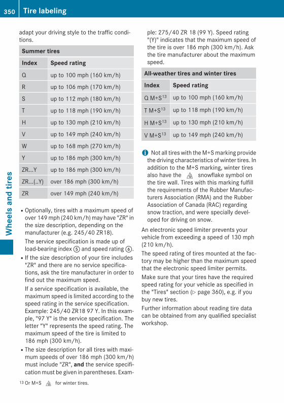
adapt your driving style to the traffic condi-tions.
Summer tires
Index Speed rating
Q up to 100 mph (160 km/h)
R up to 106 mph (170 km/h)
S up to 112 mph (180 km/h)
T up to 118 mph (190 km/h)
H up to 130 mph (210 km/h)
V up to 149 mph (240 km/h)
W up to 168 mph (270 km/h)
Y up to 186 mph (300 km/h)
ZR...Y up to 186 mph (300 km/h)
ZR...(..Y) over 186 mph (300 km/h)
ZR over 149 mph (240 km/h)
ROptionally, tires with a maximum speed ofover 149 mph (240 km/h) may have "ZR" inthe size description, depending on themanufacturer (e.g. 245/40 ZR18).The service specification is made up ofload-bearing index A and speed rating B.RIf the size description of your tire includes
"ZR" and there are no service specifica-tions, ask the tire manufacturer in order tofind out the maximum speed.If a service specification is available, themaximum speed is limited according to thespeed rating in the service specification.Example: 245/40 ZR18 97 Y. In this exam-ple, "97 Y" is the service specification. Theletter "Y" represents the speed rating. Themaximum speed of the tire is limited to186 mph (300 km/h).RThe size description for all tires with maxi-
mum speeds of over 186 mph (300 km/h)must include "ZR", and the service specifi-cation must be given in parentheses. Exam-
ple: 275/40 ZR 18 (99 Y). Speed rating"(Y)" indicates that the maximum speed ofthe tire is over 186 mph (300 km/h). Askthe tire manufacturer about the maximumspeed.
All-weather tires and winter tires
Index Speed rating
Q M+S13 up to 100 mph (160 km/h)
T M+S13 up to 118 mph (190 km/h)
H M+S13 up to 130 mph (210 km/h)
V M+S13 up to 149 mph (240 km/h)
i Not all tires with the M+S marking providethe driving characteristics of winter tires. Inaddition to the M+S marking, winter tiresalso have the i snowflake symbol onthe tire wall. Tires with this marking fulfillthe requirements of the Rubber Manufac-turers Association (RMA) and the RubberAssociation of Canada (RAC) regardingsnow traction, and were specially devel-oped for driving on snow.
An electronic speed limiter prevents yourvehicle from exceeding a speed of 130 mph(210 km/h).The speed rating of tires mounted at the fac-tory may be higher than the maximum speedthat the electronic speed limiter permits.Make sure that your tires have the requiredspeed rating for your vehicle as specified inthe "Tires" section (Y page 360), e.g. if youbuy new tires.Further information about reading tire datacan be obtained from any qualified specialistworkshop.
13 Or M+S i for winter tires.
350 Tire labelingW
heel
s an
d tir
es
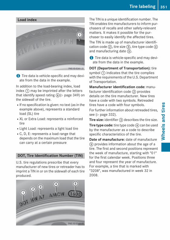
Load index
i Tire data is vehicle-specific and may devi-ate from the data in the example.
In addition to the load-bearing index, loadindex : may be imprinted after the lettersthat identify speed rating B(Y page 349) onthe sidewall of the tire.RIf no specification is given: no text (as in the
example above), represents a standardload (SL) tireRXL or Extra Load: represents a reinforced
tireRLight Load: represents a light load tireRC, D, E: represents a load range that
depends on the maximum load that the tirecan carry at a certain pressure
DOT, Tire Identification Number (TIN)U.S. tire regulations prescribe that everymanufacturer of new tires or retreader has toimprint a TIN in or on the sidewall of each tireproduced.
The TIN is a unique identification number. TheTIN enables tire manufacturers to inform pur-chasers of recalls and other safety-relevantmatters. It makes it possible for the pur-chaser to easily identify the affected tires.The TIN is made up of manufacturer identifi-cation code ;, tire size =, tire type code ?and manufacturing date A.
i Tire data is vehicle-specific and may devi-ate from the data in the example.
DOT (Department of Transportation): tiresymbol : indicates that the tire complieswith the requirements of the U.S. Departmentof Transportation.Manufacturer identification code: manu-facturer identification code ; providesdetails on the tire manufacturer. New tireshave a code with two symbols. Retreadedtires have a code with four symbols.For further information about retreaded tires,see (Y page 332).Tire size: identifier = describes the tire size.Tire type code: tire type code ? can be usedby the manufacturer as a code to describespecific characteristics of the tire.Date of manufacture: date of manufactureA provides information about the age of atire. The first and second positions representthe week of manufacture, starting with "01"for the first calendar week. Positions threeand four represent the year of manufacture.For example, a tire that is marked with"3208", was manufactured in week 32 in2008.
Tire labeling 351
Whe
els
and
tires
Z
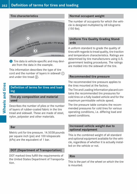
Tire characteristics
i Tire data is vehicle-specific and may devi-ate from the data in the example.
This information describes the type of tirecord and the number of layers in sidewall :and under tire tread ;.
Definition of terms for tires and load-ing
Tire ply composition and materialused
Describes the number of plies or the numberof layers of rubber-coated fabric in the tiretread and sidewall. These are made of steel,nylon, polyester and other materials.
BarMetric unit for tire pressure. 14.5038 poundsper square inch (psi) and 100 kilopascals(kPa) are the equivalent of 1 bar.
DOT (Department of Transportation)DOT marked tires fulfill the requirements ofthe United States Department of Transporta-tion.
Normal occupant weightThe number of occupants for which the vehi-cle is designed multiplied by 68 kilograms(150 lbs).
Uniform Tire Quality Grading Stand-ards
A uniform standard to grade the quality oftires with regards to tread quality, tire tractionand temperature characteristics. Ratings aredetermined by tire manufacturers using U.S.government testing procedures. The ratingsare molded into the sidewall of the tire.
Recommended tire pressureThe recommended tire pressure applies tothe tires mounted at the factory.The Tire and Loading Information placard con-tains the recommended tire pressures forcold tires on a fully loaded vehicle and for themaximum permissible vehicle speed.The tire pressure table contains the recom-mended pressures for cold tires for variousoperating conditions, i.e. differing load andspeed conditions.
Increased vehicle weight due tooptional equipment
This is the combined weight of all standardand optional equipment available for the vehi-cle, regardless of whether it is actually instal-led on the vehicle or not.
RimThis is the part of the wheel on which the tireis mounted.
352 Definition of terms for tires and loadingW
heel
s an
d tir
es
GAWR (Gross Axle Weight Rating)The GAWR is the maximum gross axle weightrating. The actual load on an axle must neverexceed the gross axle weight rating. Thegross axle weight rating can be found on thevehicle identification plate on the B-pillar onthe driver's side.
Speed ratingThe speed rating is part of the tire identifica-tion. It specifies the speed range for which thetire is approved.
GTW (Gross Trailer Weight)The GTW is the weight of a trailer including theweight of the load, luggage, accessories etc.on the trailer.
GVW (Gross Vehicle Weight)The gross vehicle weight includes the weightof the vehicle including fuel, tools, the sparewheel, accessories installed, occupants, lug-gage and the drawbar noseweight, if applica-ble. The gross vehicle weight must not exceedthe gross vehicle weight rating GVWR asspecified on the vehicle identification plate onthe B-pillar on the driver's side.
GVWR (Gross Vehicle Weight Rating)The GVWR is the maximum permissible grossweight of a fully loaded vehicle (the weight ofthe vehicle including all accessories, occu-pants, fuel, luggage and the drawbar nose-weight, if applicable). The gross vehicleweight rating is specified on the vehicle iden-tification plate on the B-pillar on the driver'sside.
Maximum loaded vehicle weightThe maximum weight is the sum of the curbweight of the vehicle, the weight of the acces-sories, the total load limit and the weight ofthe optional equipment installed at the fac-tory.
Kilopascal (kPa)Metric unit for tire pressure. 6.9 kPa corre-sponds to 1 psi. Another unit for tire pressureis bar. 100 kilopascals (kPa) are the equiva-lent of 1 bar.
Load indexIn addition to the load-bearing index, the loadindex may also be imprinted on the sidewall ofthe tire. This specifies the load-bearing capa-city more precisely.
Curb weightThe weight of a vehicle with standard equip-ment including the maximum capacity of fuel,oil and coolant. It also includes the air-condi-tioning system and optional equipment ifthese are installed in the vehicle, but does notinclude passengers or luggage.
Maximum load ratingThe maximum load rating in kilograms orpounds is the maximum weight for which atire is approved.
Maximum permissible tire pressureMaximum permissible tire pressure for onetire.
Definition of terms for tires and loading 353
Whe
els
and
tires
Z

Maximum load on one tireMaximum load on one tire. This is calculatedby dividing the maximum axle load of one axleby two.
PSI (pounds per square inch)A standard unit of measure for tire pressure.
Aspect ratioRelationship between tire height and tirewidth in percent.
Tire pressureThis is pressure inside the tire applying anoutward force to each square inch of the tire'ssurface. The tire pressure is specified inpounds per square inch (psi), in kilopascal(kPa) or in bar. The tire pressure should onlybe corrected when the tires are cold.
Tire pressure of cold tiresThe tires are cold:Rif the vehicle has been parked without
direct sunlight on the tires for at least threehours andRif the vehicle has not been driven further
than 1 mile (1.6 km)
TreadThe part of the tire that comes into contactwith the road.
BeadThe tire bead ensures that the tire sitssecurely on the wheel. There are several steelwires in the bead to prevent the tire fromcoming loose from the wheel rim.
SidewallThe part of the tire between the tread and thebead.
Weight of optional extrasThe combined weight of those optional extrasthat weigh more than the replaced standardparts and more than 2.3 kg (5 lbs). Theseoptional extras, such as high-performancebrakes, level control, a roof rack or a high-performance battery, are not included in thecurb weight and the weight of the accesso-ries.
TIN (Tire Identification Number)This is a unique identifier which can be usedby a tire manufacturer to identify tires, forexample for a product recall, and thus identifythe purchasers. The TIN is made up of themanufacturer's identity code, tire size, tiretype code and the manufacturing date.
Load bearing indexThe load bearing index (also load index) is acode that contains the maximum load bearingcapacity of a tire.
TractionTraction is the result of friction between thetires and the road surface.
TWR (Tongue Weight Rating)The TWR specifies the maximum permissibleweight that the ball coupling of the trailer towhitch can support.
354 Definition of terms for tires and loadingW
heel
s an
d tir
es
Treadwear indicatorsNarrow bars (tread wear bars) that are dis-tributed over the tire tread. If the tire tread islevel with the bars, the wear limit of á in(1.6 mm) has been reached.
Occupant distributionThe distribution of occupants in a vehicle attheir designated seating positions.
Total load limitNominal load and luggage load plus 68 kg(150 lbs) multiplied by the number of seats inthe vehicle.
Changing a wheel
Flat tireYou can find information on what to do in theevent of a flat tire in the "Flat tire" section(Y page 314).Information on driving with MOExtended tiresin the event of a flat tire can be found under"MOExtended tires (tires with run-flat char-acteristics" (Y page 315).
Rotating the wheels
G WARNINGInterchanging the front and rear wheels mayseverely impair the driving characteristics ifthe wheels or tires have different dimensions.The wheel brakes or suspension componentsmay also be damaged. There is a risk of acci-dent.Rotate front and rear wheels only if the wheelsand tires are of the same dimensions.
! On vehicles equipped with a tire pressuremonitor, electronic components are loca-ted in the wheel.
Tire-mounting tools should not be usednear the valve. This could damage the elec-tronic components.Only have tires changed at a qualified spe-cialist workshop.
Always observe the instructions and safetynotes in the "Mounting a wheel" section(Y page 356).The wear patterns on the front and rear tiresdiffer, depending on the operating conditions.Rotate the wheels before a clear wear patternhas formed on the tires. Front tires typicallywear more on the shoulders and the rear tiresin the center.If your vehicle's tire configuration allows, youcan rotate the wheels according to the inter-vals in the tire manufacturer's warranty bookin your vehicle documents. If no warrantybook is available, the tires should be rotatedevery 3,000 to 6,000 miles (5,000 to10,000 km), or earlier if tire wear requires. Donot change the direction of wheel rotation.Clean the contact surfaces of the wheel andthe brake disc thoroughly every time a wheelis rotated. Check the tire pressure and reac-tivate the tire pressure monitor if necessary.Information on changing tires and mountingthe spare wheel (Y page 355).
Direction of rotationTires with a specified direction of rotationhave additional benefits, e.g. if there is a riskof hydroplaning. These advantages can onlybe gained if the tires are installed correspond-ing to the direction of rotation.An arrow on the sidewall of the tire indicatesits correct direction of rotation.
Storing wheelsStore wheels that are not being used in a cool,dry and preferably dark place. Protect thetires from oil, grease, gasoline and diesel.
Changing a wheel 355
Whe
els
and
tires
Z
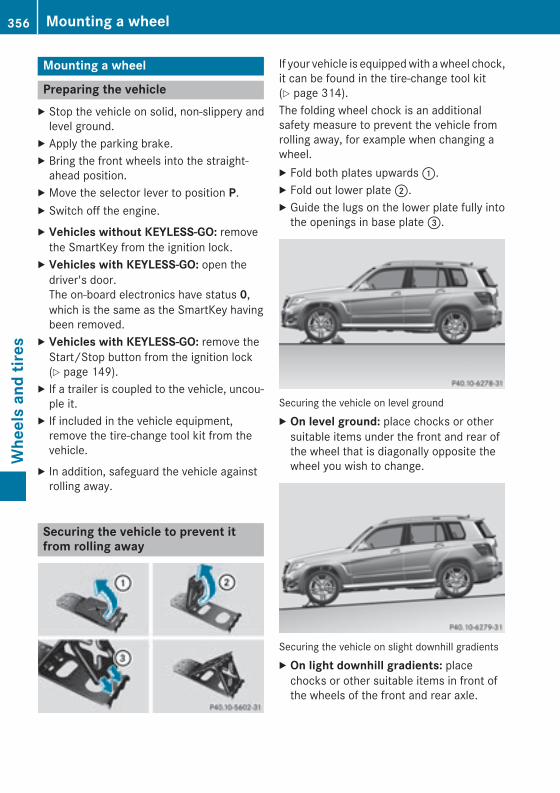
Mounting a wheel
Preparing the vehicleX Stop the vehicle on solid, non-slippery and
level ground.X Apply the parking brake.X Bring the front wheels into the straight-
ahead position.X Move the selector lever to position P.X Switch off the engine.X Vehicles without KEYLESS-GO: remove
the SmartKey from the ignition lock.X Vehicles with KEYLESS-GO: open the
driver's door.The on-board electronics have status 0,which is the same as the SmartKey havingbeen removed.
X Vehicles with KEYLESS-GO: remove theStart/Stop button from the ignition lock(Y page 149).
X If a trailer is coupled to the vehicle, uncou-ple it.
X If included in the vehicle equipment,remove the tire-change tool kit from thevehicle.
X In addition, safeguard the vehicle againstrolling away.
Securing the vehicle to prevent itfrom rolling away
If your vehicle is equipped with a wheel chock,it can be found in the tire-change tool kit(Y page 314).The folding wheel chock is an additionalsafety measure to prevent the vehicle fromrolling away, for example when changing awheel.X Fold both plates upwards :.X Fold out lower plate ;.X Guide the lugs on the lower plate fully into
the openings in base plate =.
Securing the vehicle on level groundX On level ground: place chocks or other
suitable items under the front and rear ofthe wheel that is diagonally opposite thewheel you wish to change.
Securing the vehicle on slight downhill gradientsX On light downhill gradients: place
chocks or other suitable items in front ofthe wheels of the front and rear axle.
356 Mounting a wheelW
heel
s an
d tir
es
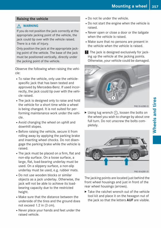
Raising the vehicle
G WARNINGIf you do not position the jack correctly at theappropriate jacking point of the vehicle, thejack could tip over with the vehicle raised.There is a risk of injury.Only position the jack at the appropriate jack-ing point of the vehicle. The base of the jackmust be positioned vertically, directly underthe jacking point of the vehicle.
Observe the following when raising the vehi-cle:RTo raise the vehicle, only use the vehicle-
specific jack that has been tested andapproved by Mercedes-Benz. If used incor-rectly, the jack could tip over with the vehi-cle raised.RThe jack is designed only to raise and hold
the vehicle for a short time while a wheelis being changed. It is not suited for per-forming maintenance work under the vehi-cle.RAvoid changing the wheel on uphill and
downhill slopes.RBefore raising the vehicle, secure it from
rolling away by applying the parking brakeand inserting wheel chocks. Do not disen-gage the parking brake while the vehicle israised.RThe jack must be placed on a firm, flat and
non-slip surface. On a loose surface, alarge, flat, load-bearing underlay must beused. On a slippery surface, a non-slipunderlay must be used, e.g. rubber mats.RDo not use wooden blocks or similar
objects as a jack underlay. Otherwise, thejack will not be able to achieve its load-bearing capacity due to the restrictedheight.RMake sure that the distance between the
underside of the tires and the ground doesnot exceed 1.2 in (3 cm).RNever place your hands and feet under the
raised vehicle.
RDo not lie under the vehicle.RDo not start the engine when the vehicle is
raised.RNever open or close a door or the tailgate
when the vehicle is raised.RMake sure that no persons are present in
the vehicle when the vehicle is raised.
! The jack is designed exclusively for jack-ing up the vehicle at the jacking points.Otherwise, your vehicle could be damaged.
X Using lug wrench :, loosen the bolts onthe wheel you wish to change by about onefull turn. Do not unscrew the bolts com-pletely.
The jacking points are located just behind thefront wheel housings and just in front of therear wheel housings (arrows).X Take the ratchet wrench out of the vehicle
tool kit and place it on the hexagon nut ofthe jack so that the letters AUF are visible.
Mounting a wheel 357
Whe
els
and
tires
Z
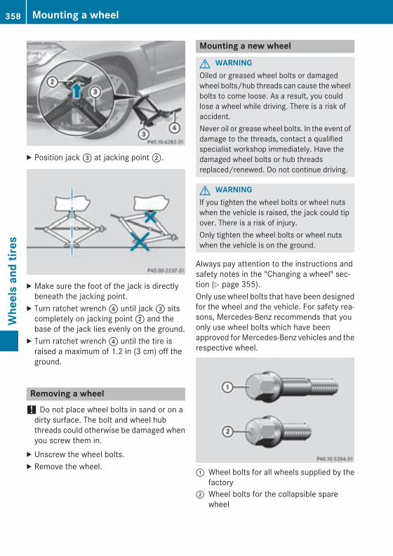
X Position jack = at jacking point ;.
X Make sure the foot of the jack is directlybeneath the jacking point.
X Turn ratchet wrench ? until jack = sitscompletely on jacking point ; and thebase of the jack lies evenly on the ground.
X Turn ratchet wrench ? until the tire israised a maximum of 1.2 in (3 cm) off theground.
Removing a wheel! Do not place wheel bolts in sand or on a
dirty surface. The bolt and wheel hubthreads could otherwise be damaged whenyou screw them in.
X Unscrew the wheel bolts.X Remove the wheel.
Mounting a new wheel
G WARNINGOiled or greased wheel bolts or damagedwheel bolts/hub threads can cause the wheelbolts to come loose. As a result, you couldlose a wheel while driving. There is a risk ofaccident.Never oil or grease wheel bolts. In the event ofdamage to the threads, contact a qualifiedspecialist workshop immediately. Have thedamaged wheel bolts or hub threadsreplaced/renewed. Do not continue driving.
G WARNINGIf you tighten the wheel bolts or wheel nutswhen the vehicle is raised, the jack could tipover. There is a risk of injury.Only tighten the wheel bolts or wheel nutswhen the vehicle is on the ground.
Always pay attention to the instructions andsafety notes in the "Changing a wheel" sec-tion (Y page 355).Only use wheel bolts that have been designedfor the wheel and the vehicle. For safety rea-sons, Mercedes-Benz recommends that youonly use wheel bolts which have beenapproved for Mercedes-Benz vehicles and therespective wheel.
: Wheel bolts for all wheels supplied by thefactory
; Wheel bolts for the collapsible sparewheel
358 Mounting a wheelW
heel
s an
d tir
es
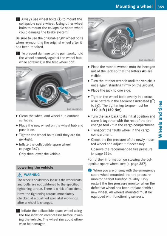
! Always use wheel bolts ; to mount thecollapsible spare wheel. Using other wheelbolts to mount the collapsible spare wheelcould damage the brake system.
Be sure to use the original-length wheel boltswhen re-mounting the original wheel after ithas been repaired.
! To prevent damage to the paintwork, holdthe wheel securely against the wheel hubwhile screwing in the first wheel bolt.
X Clean the wheel and wheel hub contactsurfaces.
X Place the new wheel on the wheel hub andpush it on.
X Tighten the wheel bolts until they are fin-ger-tight.
X Inflate the collapsible spare wheel(Y page 367).Only then lower the vehicle.
Lowering the vehicle
G WARNINGThe wheels could work loose if the wheel nutsand bolts are not tightened to the specifiedtightening torque. There is a risk of accident.Have the tightening torque immediatelychecked at a qualified specialist workshopafter a wheel is changed.
! Inflate the collapsible spare wheel usingthe tire inflation compressor before lower-ing the vehicle. The wheel rim could other-wise be damaged.
X Place the ratchet wrench onto the hexagonnut of the jack so that the letters AB arevisible.
X Turn the ratchet wrench until the vehicle isonce again standing firmly on the ground.
X Place the jack to one side.X Tighten the wheel bolts evenly in a cross-
wise pattern in the sequence indicated (:to A). The tightening torque must be110 lb-ft (150 Nm).
X Turn the jack back to its initial position andstore it together with the rest of the tire-change tool kit in the cargo compartment.
X Transport the faulty wheel in the cargocompartment.
X Check the tire pressure of the newly moun-ted wheel and adjust it if necessary.Observe the recommended tire pressure(Y page 336).
For further information on stowing the col-lapsible spare wheel, see (Y page 367).
i When you are driving with the emergencyspare wheel mounted, the tire pressuremonitor cannot function reliably. Onlyrestart the tire pressure monitor when thedefective wheel has been replaced with anew wheel. All wheels mounted must beequipped with functioning sensors.
Mounting a wheel 359
Whe
els
and
tires
Z
Wheel and tire combinations
General notes! For safety reasons, Mercedes-Benz rec-
ommends that you only use tires andwheels which have been approved byMercedes-Benz specifically for your vehi-cle.These tires have been specially adapted foruse with the control systems, such as ABSor ESP®, and are marked as follows:RMO = Mercedes-Benz OriginalRMOE = Mercedes-Benz Original Extended
(tires featuring run-flat characteristics)RMO1 = Mercedes-Benz Original (only cer-
tain AMG tires)Mercedes-Benz Original Extended tiresmay only be used on wheels that have beenspecifically approved by Mercedes-Benz.Only use tires, wheels or accessories tes-ted and approved by Mercedes-Benz. Cer-tain characteristics, e.g. handling, vehiclenoise emissions or fuel consumption, mayotherwise be adversely affected. In addi-tion, when driving with a load, tire dimen-sion variations could cause the tires tocome into contact with the bodywork andaxle components. This could result in dam-age to the tires or the vehicle.Mercedes-Benz accepts no liability fordamage resulting from the use of tires,wheels or accessories other than those tes-ted and approved.Information on tires, wheels and approvedcombinations can be obtained from anyqualified specialist workshop.
Overview of abbreviations used in the follow-ing tire tables:RBA: both axlesRFA: front axleRRA: rear axle
The recommended pressures for variousoperating conditions can be found:Ron the Tire and Loading Information placard
with the recommended tire pressures onthe B-pillar on the driver's sideRin the tire pressure table on the inside of the
fuel filler flapObserve the notes on recommended tirepressures under various operating conditions(Y page 336).Check tire pressures regularly, and only whenthe tires are cold. Comply with the mainte-nance recommendations of the tire manufac-turer in the vehicle document wallet.Notes on the vehicle equipment – alwaysequip the vehicle with:Rtires of the same size on a given axle (left/
right)Rthe same type of tires at a given time (sum-
mer tires, winter tires, MOExtended tires)Exception: it is permissible to install a dif-ferent type or make in the event of a flattire. Observe the "MOExtended tires (tireswith run-flat characteristics" section(Y page 315).
Vehicles equipped with MOExtended tires arenot equipped with a TIREFIT kit at the factory.It is therefore recommended that you addi-tionally equip your vehicle with a TIREFIT kit ifyou mount tires that do not feature run-flatproperties, e.g. winter tires. A TIREFIT kit maybe obtained from a qualified specialist work-shop.
i Not all wheel and tire combinations areavailable at the factory for all countries.
i The following pages contain informationon approved wheel rims and tire sizes forequipping your vehicle with winter tires.Winter tires are not available at the factoryas standard equipment or optional extras.If you want to equip your vehicle withapproved winter tires, it may be necessaryto obtain wheel rims in the correspondingsize. The size of the approved winter tiresmay differ from the standard tires. This is
360 Wheel and tire combinationsW
heel
s an
d tir
es
dependent on the model and the equip-ment installed at the factory.The tires and wheel rims, as well as furtherinformation, can be obtained at a qualifiedspecialist workshop.
Wheel and tire combinations 361
Whe
els
and
tires
Z
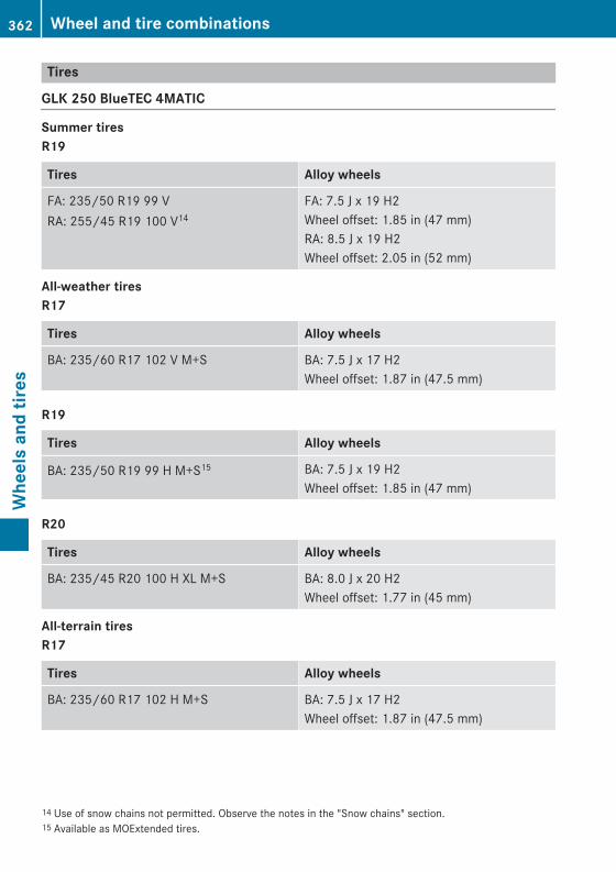
Tires
GLK 250 BlueTEC 4MATIC
Summer tiresR19
Tires Alloy wheels
FA: 235/50 R19 99 VRA: 255/45 R19 100 V14
FA: 7.5 J x 19 H2Wheel offset: 1.85 in (47 mm)RA: 8.5 J x 19 H2Wheel offset: 2.05 in (52 mm)
All-weather tiresR17
Tires Alloy wheels
BA: 235/60 R17 102 V M+S BA: 7.5 J x 17 H2Wheel offset: 1.87 in (47.5 mm)
R19
Tires Alloy wheels
BA: 235/50 R19 99 H M+S15 BA: 7.5 J x 19 H2Wheel offset: 1.85 in (47 mm)
R20
Tires Alloy wheels
BA: 235/45 R20 100 H XL M+S BA: 8.0 J x 20 H2Wheel offset: 1.77 in (45 mm)
All-terrain tiresR17
Tires Alloy wheels
BA: 235/60 R17 102 H M+S BA: 7.5 J x 17 H2Wheel offset: 1.87 in (47.5 mm)
14 Use of snow chains not permitted. Observe the notes in the "Snow chains" section.15 Available as MOExtended tires.
362 Wheel and tire combinationsW
heel
s an
d tir
es
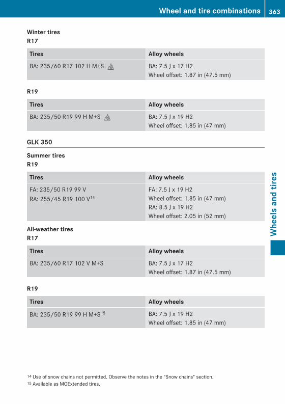
Winter tiresR17
Tires Alloy wheels
BA: 235/60 R17 102 H M+Si BA: 7.5 J x 17 H2Wheel offset: 1.87 in (47.5 mm)
R19
Tires Alloy wheels
BA: 235/50 R19 99 H M+Si BA: 7.5 J x 19 H2Wheel offset: 1.85 in (47 mm)
GLK 350
Summer tiresR19
Tires Alloy wheels
FA: 235/50 R19 99 VRA: 255/45 R19 100 V14
FA: 7.5 J x 19 H2Wheel offset: 1.85 in (47 mm)RA: 8.5 J x 19 H2Wheel offset: 2.05 in (52 mm)
All-weather tiresR17
Tires Alloy wheels
BA: 235/60 R17 102 V M+S BA: 7.5 J x 17 H2Wheel offset: 1.87 in (47.5 mm)
R19
Tires Alloy wheels
BA: 235/50 R19 99 H M+S15 BA: 7.5 J x 19 H2Wheel offset: 1.85 in (47 mm)
14 Use of snow chains not permitted. Observe the notes in the "Snow chains" section.15 Available as MOExtended tires.
Wheel and tire combinations 363
Whe
els
and
tires
Z
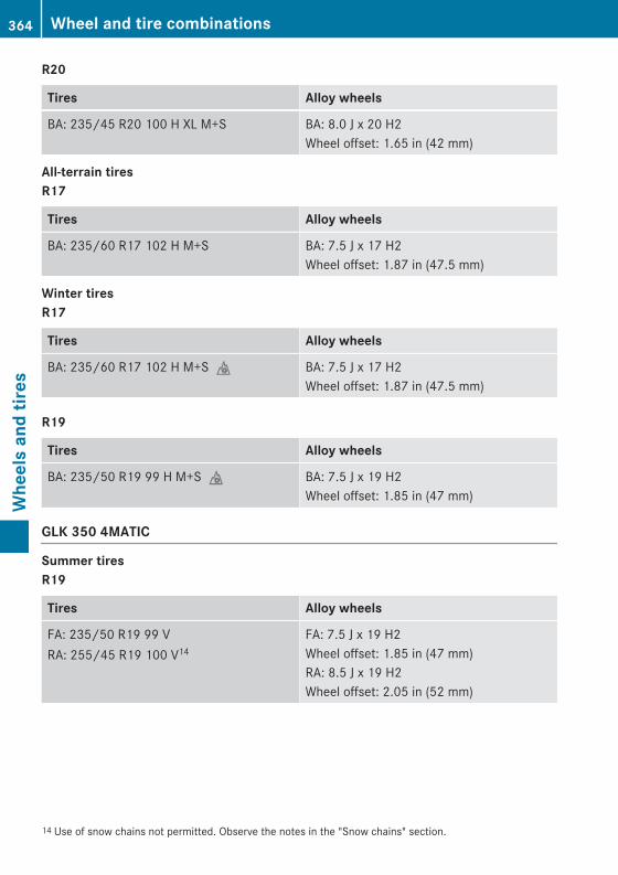
R20
Tires Alloy wheels
BA: 235/45 R20 100 H XL M+S BA: 8.0 J x 20 H2Wheel offset: 1.65 in (42 mm)
All-terrain tiresR17
Tires Alloy wheels
BA: 235/60 R17 102 H M+S BA: 7.5 J x 17 H2Wheel offset: 1.87 in (47.5 mm)
Winter tiresR17
Tires Alloy wheels
BA: 235/60 R17 102 H M+Si BA: 7.5 J x 17 H2Wheel offset: 1.87 in (47.5 mm)
R19
Tires Alloy wheels
BA: 235/50 R19 99 H M+Si BA: 7.5 J x 19 H2Wheel offset: 1.85 in (47 mm)
GLK 350 4MATIC
Summer tiresR19
Tires Alloy wheels
FA: 235/50 R19 99 VRA: 255/45 R19 100 V14
FA: 7.5 J x 19 H2Wheel offset: 1.85 in (47 mm)RA: 8.5 J x 19 H2Wheel offset: 2.05 in (52 mm)
14 Use of snow chains not permitted. Observe the notes in the "Snow chains" section.
364 Wheel and tire combinationsW
heel
s an
d tir
es
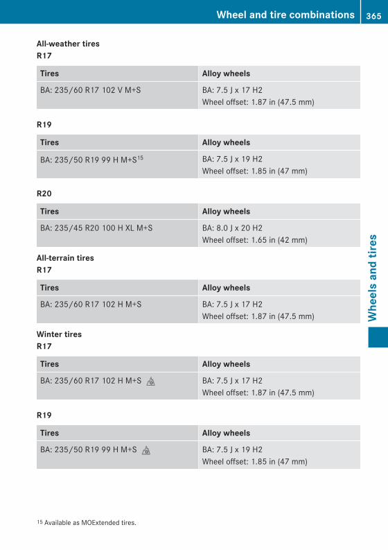
All-weather tiresR17
Tires Alloy wheels
BA: 235/60 R17 102 V M+S BA: 7.5 J x 17 H2Wheel offset: 1.87 in (47.5 mm)
R19
Tires Alloy wheels
BA: 235/50 R19 99 H M+S15 BA: 7.5 J x 19 H2Wheel offset: 1.85 in (47 mm)
R20
Tires Alloy wheels
BA: 235/45 R20 100 H XL M+S BA: 8.0 J x 20 H2Wheel offset: 1.65 in (42 mm)
All-terrain tiresR17
Tires Alloy wheels
BA: 235/60 R17 102 H M+S BA: 7.5 J x 17 H2Wheel offset: 1.87 in (47.5 mm)
Winter tiresR17
Tires Alloy wheels
BA: 235/60 R17 102 H M+Si BA: 7.5 J x 17 H2Wheel offset: 1.87 in (47.5 mm)
R19
Tires Alloy wheels
BA: 235/50 R19 99 H M+Si BA: 7.5 J x 19 H2Wheel offset: 1.85 in (47 mm)
15 Available as MOExtended tires.
Wheel and tire combinations 365
Whe
els
and
tires
Z
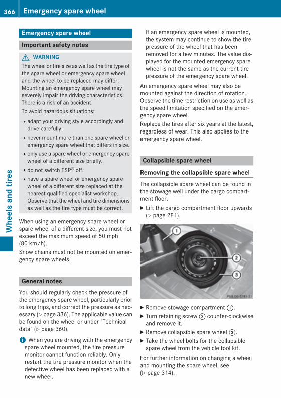
Emergency spare wheel
Important safety notes
G WARNINGThe wheel or tire size as well as the tire type ofthe spare wheel or emergency spare wheeland the wheel to be replaced may differ.Mounting an emergency spare wheel mayseverely impair the driving characteristics.There is a risk of an accident.To avoid hazardous situations:Radapt your driving style accordingly and
drive carefully.Rnever mount more than one spare wheel or
emergency spare wheel that differs in size.Ronly use a spare wheel or emergency spare
wheel of a different size briefly.Rdo not switch ESP® off.Rhave a spare wheel or emergency spare
wheel of a different size replaced at thenearest qualified specialist workshop.Observe that the wheel and tire dimensionsas well as the tire type must be correct.
When using an emergency spare wheel orspare wheel of a different size, you must notexceed the maximum speed of 50 mph(80 km/h).Snow chains must not be mounted on emer-gency spare wheels.
General notesYou should regularly check the pressure ofthe emergency spare wheel, particularly priorto long trips, and correct the pressure as nec-essary (Y page 336). The applicable value canbe found on the wheel or under "Technicaldata" (Y page 360).
i When you are driving with the emergencyspare wheel mounted, the tire pressuremonitor cannot function reliably. Onlyrestart the tire pressure monitor when thedefective wheel has been replaced with anew wheel.
If an emergency spare wheel is mounted,the system may continue to show the tirepressure of the wheel that has beenremoved for a few minutes. The value dis-played for the mounted emergency sparewheel is not the same as the current tirepressure of the emergency spare wheel.
An emergency spare wheel may also bemounted against the direction of rotation.Observe the time restriction on use as well asthe speed limitation specified on the emer-gency spare wheel.Replace the tires after six years at the latest,regardless of wear. This also applies to theemergency spare wheel.
Collapsible spare wheel
Removing the collapsible spare wheelThe collapsible spare wheel can be found inthe stowage well under the cargo compart-ment floor.X Lift the cargo compartment floor upwards
(Y page 281).
X Remove stowage compartment :.X Turn retaining screw ; counter-clockwise
and remove it.X Remove collapsible spare wheel =.X Take the wheel bolts for the collapsible
spare wheel from the vehicle tool kit.For further information on changing a wheeland mounting the spare wheel, see(Y page 314).
366 Emergency spare wheelW
heel
s an
d tir
es
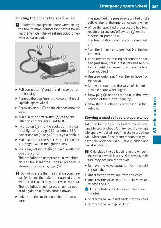
Inflating the collapsible spare wheel
! Inflate the collapsible spare wheel usingthe tire inflation compressor before lower-ing the vehicle. The wheel rim could other-wise be damaged.
X Pull connector ? and the air hose out ofthe housing.
X Remove the cap from the valve on the col-lapsible spare wheel.
X Screw union nut : on the air hose onto thevalve.
X Make sure on/off switch A of the tireinflation compressor is set to 0.
X Insert plug ? into the socket of the ciga-rette lighter (Y page 284) or into a 12 Vpower socket (Y page 284) in your vehicle.
X Make sure that the SmartKey is in position1(Y page 149) in the ignition lock.
X Press on/off switch A on the tire inflationcompressor to I.The tire inflation compressor is switchedon. The tire is inflated. The tire pressure isshown on pressure gauge =.
! Do not operate the tire inflation compres-sor for longer than eight minutes at a timewithout a break. It may otherwise overheat.The tire inflation compressor can be oper-ated again once it has cooled down.
X Inflate the tire to the specified tire pres-sure.
The specified tire pressure is printed on theyellow label of the emergency spare wheel.
X When the specified tire pressure has beenreached, press on/off switch A on theelectric air pump to 0.The tire inflation compressor is switchedoff.
X Turn the SmartKey to position 0 in the igni-tion lock.
X If the tire pressure is higher than the speci-fied pressure, press pressure release but-ton ; until the correct tire pressure hasbeen reached.
X Unscrew union nut : on the air hose fromthe valve.
X Screw the cap onto the valve of the col-lapsible spare wheel again.
X Stow plug ? and the air hose in the lowersection of the blower housing.
X Stow the tire inflation compressor in thevehicle.
Stowing a used collapsible spare wheelTake the following steps to stow a used col-lapsible spare wheel. Otherwise, the collaps-ible spare wheel will not fit in the spare wheelwell. Mercedes-Benz recommends that youhave this work carried out at a qualified spe-cialist workshop.
! Only place the collapsible spare wheel inthe vehicle when it is dry. Otherwise, mois-ture may get into the vehicle.
X Remove the valve extractor from the vehi-cle tool kit.
X Unscrew the valve cap from the valve.X Unscrew the valve insert from the valve and
release the air.i Fully deflating the tires can take a few
minutes.X Screw the valve insert back into the valve.X Screw the valve cap back on.
Emergency spare wheel 367
Whe
els
and
tires
Z
X Place the valve extractor back into the vehi-cle tool kit.
X Stow the collapsible spare wheel in theemergency spare wheel well under thecargo compartment and fasten in place.
368 Emergency spare wheelW
heel
s an
d tir
es
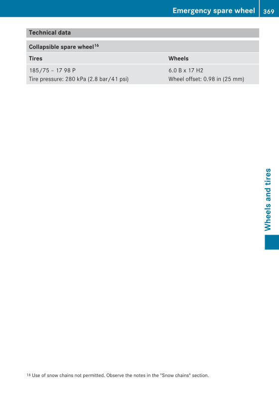
Technical data
Collapsible spare wheel16
Tires Wheels
185/75 – 17 98 PTire pressure: 280 kPa (2.8 bar/41 psi)
6.0 B x 17 H2Wheel offset: 0.98 in (25 mm)
16 Use of snow chains not permitted. Observe the notes in the "Snow chains" section.
Emergency spare wheel 369
Whe
els
and
tires
Z

370

Useful information ............................ 372Information regarding technicaldata .................................................... 372Identification plates ......................... 372Service products and filling capaci-ties ..................................................... 373Vehicle data ....................................... 380Trailer tow hitch ................................ 381
371
Tech
nica
l dat
a
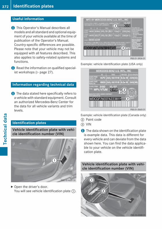
Useful information
i This Operator's Manual describes allmodels and all standard and optional equip-ment of your vehicle available at the time ofpublication of the Operator's Manual.Country-specific differences are possible.Please note that your vehicle may not beequipped with all features described. Thisalso applies to safety-related systems andfunctions.
i Read the information on qualified special-ist workshops (Y page 27).
Information regarding technical data
i The data stated here specifically refers toa vehicle with standard equipment. Consultan authorized Mercedes-Benz Center forthe data for all vehicle variants and trimlevels.
Identification plates
Vehicle identification plate with vehi-cle identification number (VIN)
X Open the driver's door.You will see vehicle identification plate :.
Example: vehicle identification plate (USA only)
Example: vehicle identification plate (Canada only); Paint code= VIN
i The data shown on the identification plateis example data. This data is different forevery vehicle and can deviate from the datashown here. You can find the data applica-ble to your vehicle on the vehicle identifi-cation plate.
Vehicle identification plate with vehi-cle identification number (VIN)
372 Identification platesTe
chni
cal d
ata
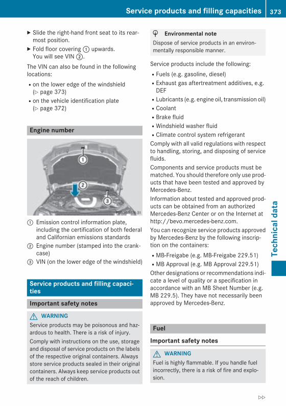
X Slide the right-hand front seat to its rear-most position.
X Fold floor covering : upwards.You will see VIN ;.
The VIN can also be found in the followinglocations:Ron the lower edge of the windshield
(Y page 373)Ron the vehicle identification plate
(Y page 372)
Engine number
: Emission control information plate,including the certification of both federaland Californian emissions standards
; Engine number (stamped into the crank-case)
= VIN (on the lower edge of the windshield)
Service products and filling capaci-ties
Important safety notes
G WARNINGService products may be poisonous and haz-ardous to health. There is a risk of injury.Comply with instructions on the use, storageand disposal of service products on the labelsof the respective original containers. Alwaysstore service products sealed in their originalcontainers. Always keep service products outof the reach of children.
H Environmental noteDispose of service products in an environ-mentally responsible manner.
Service products include the following:RFuels (e.g. gasoline, diesel)RExhaust gas aftertreatment additives, e.g.
DEFRLubricants (e.g. engine oil, transmission oil)RCoolantRBrake fluidRWindshield washer fluidRClimate control system refrigerantComply with all valid regulations with respectto handling, storing, and disposing of servicefluids.Components and service products must bematched. You should therefore only use prod-ucts that have been tested and approved byMercedes-Benz.Information about tested and approved prod-ucts can be obtained from an authorizedMercedes-Benz Center or on the Internet athttp://bevo.mercedes-benz.com.You can recognize service products approvedby Mercedes-Benz by the following inscrip-tion on the containers:RMB-Freigabe (e.g. MB-Freigabe 229.51)RMB Approval (e.g. MB Approval 229.51)Other designations or recommendations indi-cate a level of quality or a specification inaccordance with an MB Sheet Number (e.g.MB 229.5). They have not necessarily beenapproved by Mercedes-Benz.
Fuel
Important safety notes
G WARNINGFuel is highly flammable. If you handle fuelincorrectly, there is a risk of fire and explo-sion.
Service products and filling capacities 373
Tech
nica
l dat
a
Z
You must avoid fire, open flames, creatingsparks and smoking. Switch off the engineand, if applicable, the auxiliary heating beforerefueling.
G WARNINGFuel is poisonous and hazardous to health.There is a risk of injury.You must make sure that fuel does not comeinto contact with your skin, eyes or clothingand that it is not swallowed. Do not inhale fuelvapors. Keep fuel away from children.If you or others come into contact with fuel,observe the following:RWash away fuel from skin immediately
using soap and water.RIf fuel comes into contact with your eyes,
immediately rinse them thoroughly withclean water. Seek medical assistance with-out delay.RIf fuel is swallowed, seek medical assis-
tance without delay. Do not induce vomit-ing.RImmediately change out of clothing which
has come into contact with fuel.
Tank capacity
Model Total capa-city
All models 17.4 US gal(66.0 l)
Model Of whichreserve
All models Approx.2.1 US gal
(8.0 l)
Gasoline
Fuel grade! Do not use diesel to refuel vehicles with a
gasoline engine. Do not switch on the igni-tion if you accidentally refuel with thewrong fuel. Otherwise, the fuel will enterthe fuel system. Even small amounts of thewrong fuel could result in damage to thefuel system and the engine. Notify a quali-fied specialist workshop and have the fueltank and fuel lines drained completely.
! Only refuel using unleaded premiumgrade gasoline with at least 91 AKI/95 RON.
! Only use the fuel recommended. Operat-ing the vehicle with other fuels can lead toengine failure.
! Do not use the following:RE85 (gasoline with 85% ethanol)RE100 (100% ethanol)RM15 (gasoline with 15% methanol)RM30 (gasoline with 30% methanol)RM85 (gasoline with 85% methanol)RM100 (100% methanol)RGasoline with metalliferous additivesRDieselDo not mix such fuels with the fuel recom-mended for your vehicle. Do not use addi-tives. Otherwise, engine damage mayoccur. This does not include cleaning addi-tives for the removal and prevention of res-idue build-up. Gasoline may only be mixedwith cleaning additives recommended byMercedes-Benz; see "Additives". You canobtain further information from any author-ized Mercedes-Benz Center.
! To ensure the longevity and full perform-ance of the engine, only premium-gradeunleaded gasoline must be used.
374 Service products and filling capacitiesTe
chni
cal d
ata
If standard unleaded gasoline is unavaila-ble and you have to refuel with unleadedgasoline of a lower grade, observe the fol-lowing precautions:ROnly fill the fuel tank to half full with reg-
ular unleaded gasoline and fill the restwith premium-grade unleaded gasolineas soon as possible.RDo not drive at the maximum speed.RAvoid sudden acceleration and engine
speeds over 3,000 rpm.You will usually find information about the fuelgrade on the pump. If you cannot find thelabel on the pump, ask the staff for assis-tance.
i For further information, consult a quali-fied specialist workshop or visithttp://www.mbusa.com (USA only).
i E10 fuel contains up to 10% bioethanol.Your vehicle is E10-compatible. You canrefuel your vehicle using E10 fuel.
As a temporary measure, if the recommendedfuel is not available, you may also use regularunleaded gasoline with an octane rating of87 AKI/91 RON. This may reduce engine per-formance and increase fuel consumption.Avoid driving at full throttle and sudden accel-eration. Never refuel using fuel with a lowerAKI.Information on refueling (Y page 162).
Additives! Operating the engine with fuel additives
added later can lead to engine failure. Donot mix fuel additives with fuel. This doesnot include additives for the removal andprevention of residue buildup. gasolinemust only be mixed with additives recom-mended by Mercedes-Benz. Comply withthe instructions for use on the productlabel. More information about recommen-ded additives can be obtained from anyauthorized Mercedes-Benz Center.
Mercedes-Benz recommends that you usebranded fuels that have additives.
The quality of the fuel available in some coun-tries may not be sufficient. Residue couldbuild up in the injection system as a result. Insuch cases, and in consultation with anauthorized Mercedes-Benz Center, the gaso-line may be mixed with the cleaning additiverecommended by Mercedes-Benz. You mustobserve the notes and mixing ratios specifiedon the container.
Diesel
Fuel gradeG WARNINGIf you mix diesel fuel with gasoline, the flashpoint is lower than that of pure diesel fuel.When the engine is running, exhaust systemcomponents could overheat without beingnoticed. There is a risk of fire.Never refuel with gasoline. Never mix gasolinewith diesel fuel.
! Only use commercially available vehicularULTRA-LOW SULFUR DIESEL FUEL (ULSD,15 ppm maximum sulfur content) thatmeets the ASTM D975 standard. If you donot refuel with ULSD, you may damage theBlueTEC exhaust gas aftertreatment sys-tem of the vehicle.
! Do not use gasoline to refuel vehicles witha diesel engine. Do not mix diesel fuel withgasoline, kerosene or paraffin. This mayotherwise result in damage to the fuel sys-tem and engine.
You will usually find information about the fuelgrade on the pump. If you cannot find thelabel on the pump, ask the staff for assis-tance.
i For further information, consult a quali-fied specialist workshop or visithttp://www.mbusa.com (USA only).
Information on refueling (Y page 162).
Service products and filling capacities 375
Tech
nica
l dat
a
Z
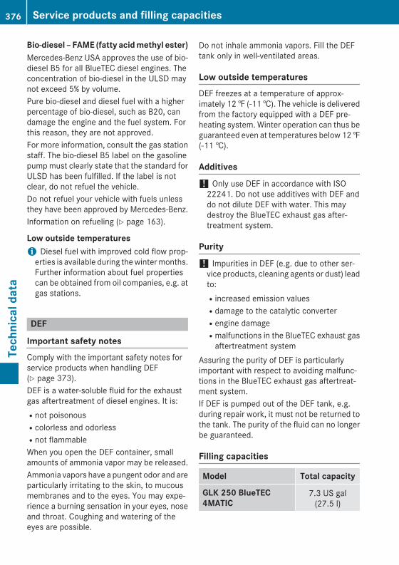
Bio-diesel – FAME (fatty acid methyl ester)Mercedes-Benz USA approves the use of bio-diesel B5 for all BlueTEC diesel engines. Theconcentration of bio-diesel in the ULSD maynot exceed 5% by volume.Pure bio-diesel and diesel fuel with a higherpercentage of bio-diesel, such as B20, candamage the engine and the fuel system. Forthis reason, they are not approved.For more information, consult the gas stationstaff. The bio-diesel B5 label on the gasolinepump must clearly state that the standard forULSD has been fulfilled. If the label is notclear, do not refuel the vehicle.Do not refuel your vehicle with fuels unlessthey have been approved by Mercedes-Benz.Information on refueling (Y page 163).
Low outside temperaturesi Diesel fuel with improved cold flow prop-
erties is available during the winter months.Further information about fuel propertiescan be obtained from oil companies, e.g. atgas stations.
DEF
Important safety notesComply with the important safety notes forservice products when handling DEF(Y page 373).DEF is a water-soluble fluid for the exhaustgas aftertreatment of diesel engines. It is:Rnot poisonousRcolorless and odorlessRnot flammableWhen you open the DEF container, smallamounts of ammonia vapor may be released.Ammonia vapors have a pungent odor and areparticularly irritating to the skin, to mucousmembranes and to the eyes. You may expe-rience a burning sensation in your eyes, noseand throat. Coughing and watering of theeyes are possible.
Do not inhale ammonia vapors. Fill the DEFtank only in well-ventilated areas.
Low outside temperaturesDEF freezes at a temperature of approx-imately 12 ‡ (-11 †). The vehicle is deliveredfrom the factory equipped with a DEF pre-heating system. Winter operation can thus beguaranteed even at temperatures below 12 ‡(-11 †).
Additives
! Only use DEF in accordance with ISO22241. Do not use additives with DEF anddo not dilute DEF with water. This maydestroy the BlueTEC exhaust gas after-treatment system.
Purity
! Impurities in DEF (e.g. due to other ser-vice products, cleaning agents or dust) leadto:Rincreased emission valuesRdamage to the catalytic converterRengine damageRmalfunctions in the BlueTEC exhaust gas
aftertreatment systemAssuring the purity of DEF is particularlyimportant with respect to avoiding malfunc-tions in the BlueTEC exhaust gas aftertreat-ment system.If DEF is pumped out of the DEF tank, e.g.during repair work, it must not be returned tothe tank. The purity of the fluid can no longerbe guaranteed.
Filling capacities
Model Total capacity
GLK 250 BlueTEC 4MATIC
7.3 US gal(27.5 l)
376 Service products and filling capacitiesTe
chni
cal d
ata
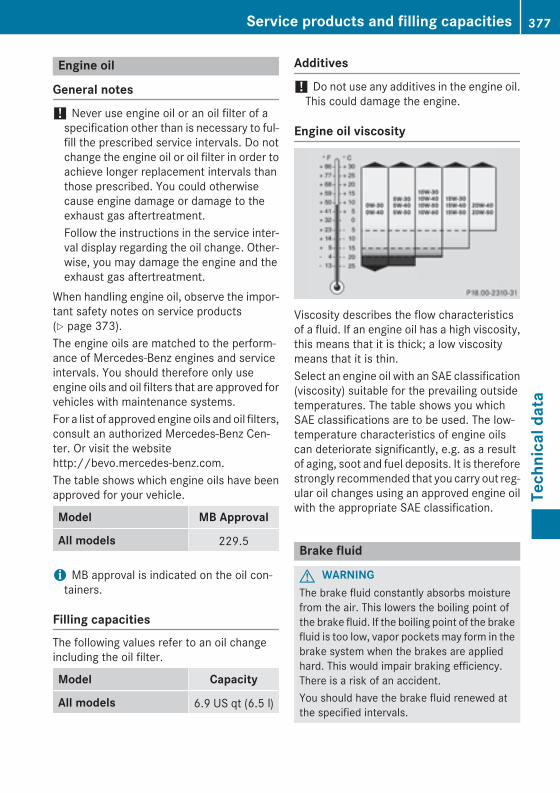
Engine oil
General notes
! Never use engine oil or an oil filter of aspecification other than is necessary to ful-fill the prescribed service intervals. Do notchange the engine oil or oil filter in order toachieve longer replacement intervals thanthose prescribed. You could otherwisecause engine damage or damage to theexhaust gas aftertreatment.Follow the instructions in the service inter-val display regarding the oil change. Other-wise, you may damage the engine and theexhaust gas aftertreatment.
When handling engine oil, observe the impor-tant safety notes on service products(Y page 373).The engine oils are matched to the perform-ance of Mercedes-Benz engines and serviceintervals. You should therefore only useengine oils and oil filters that are approved forvehicles with maintenance systems.For a list of approved engine oils and oil filters,consult an authorized Mercedes-Benz Cen-ter. Or visit the websitehttp://bevo.mercedes-benz.com.The table shows which engine oils have beenapproved for your vehicle.
Model MB Approval
All models 229.5
i MB approval is indicated on the oil con-tainers.
Filling capacitiesThe following values refer to an oil changeincluding the oil filter.
Model Capacity
All models 6.9 US qt (6.5 l)
Additives
! Do not use any additives in the engine oil.This could damage the engine.
Engine oil viscosity
Viscosity describes the flow characteristicsof a fluid. If an engine oil has a high viscosity,this means that it is thick; a low viscositymeans that it is thin.Select an engine oil with an SAE classification(viscosity) suitable for the prevailing outsidetemperatures. The table shows you whichSAE classifications are to be used. The low-temperature characteristics of engine oilscan deteriorate significantly, e.g. as a resultof aging, soot and fuel deposits. It is thereforestrongly recommended that you carry out reg-ular oil changes using an approved engine oilwith the appropriate SAE classification.
Brake fluid
G WARNINGThe brake fluid constantly absorbs moisturefrom the air. This lowers the boiling point ofthe brake fluid. If the boiling point of the brakefluid is too low, vapor pockets may form in thebrake system when the brakes are appliedhard. This would impair braking efficiency.There is a risk of an accident.You should have the brake fluid renewed atthe specified intervals.
Service products and filling capacities 377
Tech
nica
l dat
a
Z
When handling brake fluid, observe theimportant safety notes on service products(Y page 373).The brake fluid change intervals can be foundin the Maintenance Booklet.Only use brake fluid approved by Mercedes-Benz according to MB Approval 331.0.Information about approved brake fluid canbe obtained at any qualified specialist work-shop or on the Internet athttp://bevo.mercedes-benz.com.
i Have the brake fluid regularly replaced ata qualified specialist workshop and thereplacement confirmed in the MaintenanceBooklet.
Coolant
Important safety notes
G WARNINGIf antifreeze comes into contact with hot com-ponents in the engine compartment, it mayignite. There is a risk of fire and injury.Let the engine cool down before you add anti-freeze. Make sure that antifreeze is not spillednext to the filler neck. Thoroughly clean theantifreeze from components before startingthe engine.
! Only add coolant that has been premixedwith the desired antifreeze protection. Youcould otherwise damage the engine.Further information on coolants can befound in the Mercedes-Benz Specificationsfor Service Products, MB BeVo 310.1, e.g.on the Internet athttp://bevo.mercedes-benz.com. Or con-tact a qualified specialist workshop.
! Always use a suitable coolant mixture,even in countries where high temperaturesprevail.Otherwise, the engine cooling system is notsufficiently protected from corrosion andoverheating.
i Have the coolant regularly replaced at aqualified specialist workshop and thereplacement confirmed in the MaintenanceBooklet.
Comply with the important safety precautionsfor service products when handling coolant(Y page 373).The coolant is a mixture of water and anti-freeze/corrosion inhibitor. It performs thefollowing tasks:Rcorrosion protectionRantifreeze protectionRraising the boiling pointIf the coolant has antifreeze protection downto -35 ‡ (-37 †), the boiling point of the cool-ant during operation is approximately 266 ‡(130 †).The antifreeze/corrosion inhibitor concentra-tion in the engine cooling system should:Rbe at least 50%. This will protect the engine
cooling system against freezing down toapproximately -35 ‡ (-37 †).Rnot exceed 55% (antifreeze protection
down to -49 ‡ [-45 †]). Otherwise, heatwill not be dissipated as effectively.
Mercedes-Benz recommends an antifreeze/corrosion inhibitor concentrate in accord-ance with MB Specifications for Service Prod-ucts 310.1.
i When the vehicle is first delivered, it is fil-led with a coolant mixture that ensuresadequate antifreeze and corrosion protec-tion.
i The coolant is checked with every main-tenance interval at a qualified specialistworkshop.
378 Service products and filling capacitiesTe
chni
cal d
ata
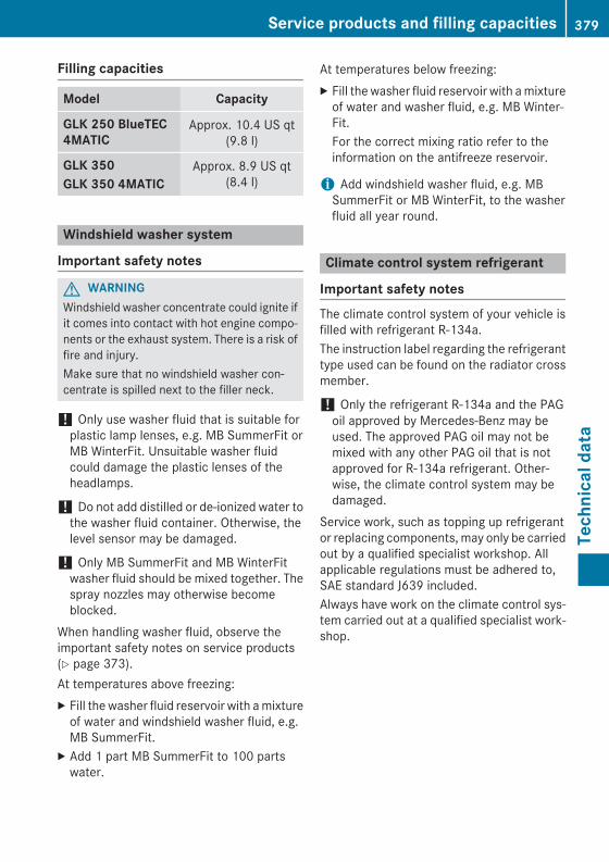
Filling capacities
Model Capacity
GLK 250 BlueTEC 4MATIC
Approx. 10.4 US qt(9.8 l)
GLK 350GLK 350 4MATIC
Approx. 8.9 US qt(8.4 l)
Windshield washer system
Important safety notes
G WARNINGWindshield washer concentrate could ignite ifit comes into contact with hot engine compo-nents or the exhaust system. There is a risk offire and injury.Make sure that no windshield washer con-centrate is spilled next to the filler neck.
! Only use washer fluid that is suitable forplastic lamp lenses, e.g. MB SummerFit orMB WinterFit. Unsuitable washer fluidcould damage the plastic lenses of theheadlamps.
! Do not add distilled or de-ionized water tothe washer fluid container. Otherwise, thelevel sensor may be damaged.
! Only MB SummerFit and MB WinterFitwasher fluid should be mixed together. Thespray nozzles may otherwise becomeblocked.
When handling washer fluid, observe theimportant safety notes on service products(Y page 373).At temperatures above freezing:X Fill the washer fluid reservoir with a mixture
of water and windshield washer fluid, e.g.MB SummerFit.
X Add 1 part MB SummerFit to 100 partswater.
At temperatures below freezing:X Fill the washer fluid reservoir with a mixture
of water and washer fluid, e.g. MB Winter-Fit.For the correct mixing ratio refer to theinformation on the antifreeze reservoir.
i Add windshield washer fluid, e.g. MBSummerFit or MB WinterFit, to the washerfluid all year round.
Climate control system refrigerant
Important safety notesThe climate control system of your vehicle isfilled with refrigerant R‑134a.The instruction label regarding the refrigeranttype used can be found on the radiator crossmember.
! Only the refrigerant R‑134a and the PAGoil approved by Mercedes-Benz may beused. The approved PAG oil may not bemixed with any other PAG oil that is notapproved for R-134a refrigerant. Other-wise, the climate control system may bedamaged.
Service work, such as topping up refrigerantor replacing components, may only be carriedout by a qualified specialist workshop. Allapplicable regulations must be adhered to,SAE standard J639 included.Always have work on the climate control sys-tem carried out at a qualified specialist work-shop.
Service products and filling capacities 379
Tech
nica
l dat
a
Z
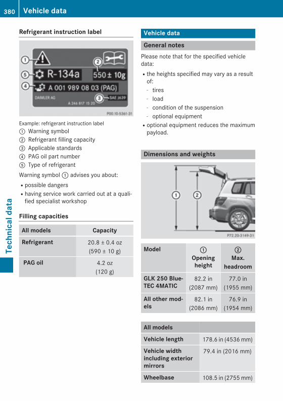
Refrigerant instruction label
Example: refrigerant instruction label: Warning symbol; Refrigerant filling capacity= Applicable standards? PAG oil part numberA Type of refrigerantWarning symbol : advises you about:Rpossible dangersRhaving service work carried out at a quali-
fied specialist workshop
Filling capacities
All models Capacity
Refrigerant 20.8 ± 0.4 oz(590 ± 10 g)
PAG oil 4.2 oz(120 g)
Vehicle data
General notesPlease note that for the specified vehicledata:Rthe heights specified may vary as a result
of:- tires- load- condition of the suspension- optional equipmentRoptional equipment reduces the maximum
payload.
Dimensions and weights
Model :
Openingheight
;
Max.headroom
GLK 250 Blue-TEC 4MATIC
82.2 in(2087 mm)
77.0 in(1955 mm)
All other mod-els
82.1 in(2086 mm)
76.9 in(1954 mm)
All models
Vehicle length 178.6 in (4536 mm)
Vehicle width including exterior mirrors
79.4 in (2016 mm)
Wheelbase 108.5 in (2755 mm)
380 Vehicle dataTe
chni
cal d
ata
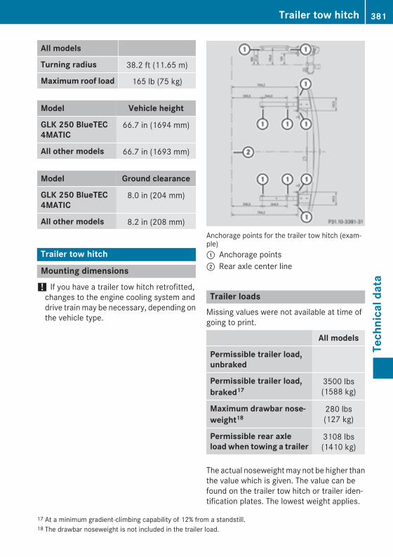
All models
Turning radius 38.2 ft (11.65 m)
Maximum roof load 165 lb (75 kg)
Model Vehicle height
GLK 250 BlueTEC 4MATIC
66.7 in (1694 mm)
All other models 66.7 in (1693 mm)
Model Ground clearance
GLK 250 BlueTEC 4MATIC
8.0 in (204 mm)
All other models 8.2 in (208 mm)
Trailer tow hitch
Mounting dimensions! If you have a trailer tow hitch retrofitted,
changes to the engine cooling system anddrive train may be necessary, depending onthe vehicle type.
Anchorage points for the trailer tow hitch (exam-ple): Anchorage points; Rear axle center line
Trailer loadsMissing values were not available at time ofgoing to print.
All models
Permissible trailer load, unbraked
Permissible trailer load, braked17
3500 lbs(1588 kg)
Maximum drawbar nose-weight18
280 lbs(127 kg)
Permissible rear axle load when towing a trailer
3108 lbs(1410 kg)
The actual noseweight may not be higher thanthe value which is given. The value can befound on the trailer tow hitch or trailer iden-tification plates. The lowest weight applies.
17 At a minimum gradient-climbing capability of 12% from a standstill.18 The drawbar noseweight is not included in the trailer load.
Trailer tow hitch 381
Tech
nica
l dat
a
Z
The maximum permissible trailer drawbarnoseweight is the maximum weight withwhich the trailer drawbar can be loaded. Limitfor Mercedes-Benz-approved trailer cou-plings.
382 Trailer tow hitchTe
chni
cal d
ata

383

384