getriebe-zubehör gear unit...
TRANSCRIPT

Maße / Dimensions in mm GG – 11/2013
Seite / Page
Ritzel- und Abtriebswellen Pinion and output drive shafts GG2 – GG4für Servo-Hochleistungsgetriebe for high-performance gear units
Verspannungs-Ritzelwellen Pre-load pinion shafts GG5 – GG7
Einstellschlüssel Adjusting wrench GG8
Schrumpfscheiben-Spannsätze Shrink-disc clamping sets GH1
Schmiereinheiten Lubrication units ZE5 – ZE6
Getriebe-ZubehörGear unit accessories
Maße / Dimensions in mmGG – 2 1/2015
x dwz dk b d1h6 d2 L1 I1 I2 I3 u t G a
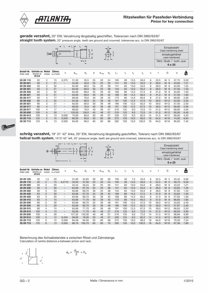
gerade verzahnt, 20° EW, Verzahnung längsballig geschliffen, Toleranzen nach DIN 3962/63/67straight tooth system, 20° pressure angle, teeth are ground and crowned, tolerances acc. to DIN 3962/63/67
Ritzelwellen für Passfeder-VerbindungPinion for key connection
u
d1
t
l1 l2 l3
b
d2
dw
zd
k
L1
G
schräg verzahnt, 19° 31‘ 42" links, 20° EW, Verzahnung längsballig geschliffen, Toleranz nach DIN 3962/63/67helical tooth system, 19°31’42" left, 20° pressure angle, teeth are ground and crowned, tolerances acc. to DIN 3962/63/67
d1
t
l1 l2 l3
G
d2
dw
z
dk
L1
b
u
a o
Berechnung des Achsabstandes a zwischen Ritzel und Zahnstange.Calculation of centre distance a between pinion and rack.
ao = dwz2
+ ho
20 29 120 32 1,5 20 – 31,83 34,83 20 20 26 100 40 7,5 45,0 6 22,5 M 5 33,42 0,6020 29 115 32 2 15 0,4172 33,50 37,50 25 20 24 105 28 13,5 50,0 6 22,5 M 5 39,75 0,5020 29 020 50 2 20 – 42,44 46,44 25 25 35 141 63 13,0 53,0 8 28,0 M 8 43,22 1,2120 29 330 50 2 30 – 63,66 67,70 25 25 38 141 63 13,0 53,0 8 28,0 M 8 53,83 1,2520 29 320 50 3 20 – 63,66 69,70 30 25 38 143 63 13,0 55,0 8 28,0 M 8 57,83 1,3320 29 430 63 2 30 – 63,66 67,70 25 28 42 166 80 14,5 57,5 8 31,0 M 8 53,83 1,5020 29 420 63 3 20 – 63,66 69,70 30 28 42 168 80 14,5 60,0 8 31,0 M 8 57,83 1,6020 29 415 63 4 15 – 63,66 71,70 40 28 42 173 80 14,5 65,0 8 31,0 M 8 66,83 1,8520 29 530 80 2 30 – 63,66 69,70 25 36 48 181 100 12,5 57,0 10 39,0 M 12 53,83 2,4020 29 520 80 3 20 – 63,66 69,70 30 36 48 186 100 12,5 62,0 10 39,0 M 12 57,87 2,4020 29 515 80 4 15 – 63,66 71,70 40 36 48 191 100 12,5 67,0 10 39,0 M 12 66,83 2,5020 29 615 100 4 15 – 63,66 71,70 40 48 57 216 125 9,0 72,0 14 51,5 M 12 66,83 3,9020 29 630 100 4 30 – 127,32 135,30 40 48 57 216 125 9,0 72,0 14 51,5 M 12 98,66 6,9020 29 612 100 5 12 0,434 68,00 78,00 50 48 57 226 125 9,0 82,0 14 51,5 M 12 68,00 4,2020 29 715 125 5 15 0,500 84,58 94,50 50 60 68 272 150 10,0 90,0 18 64,0 M 16 76,29 7,2420 29 713 125 6 13 0,500 88,76 100,70 60 60 70 282 150 10,0 100,0 18 64,0 M 16 87,38 7,89
20 28 115 32 2 15 0,375 31,50 35,5 25 20 24 105 28 13,5 50,0 6 22,5 M 5 37,75 0,5020 28 021 50 2 21 – 42,00 46,0 25 25 35 141 63 13,0 53,0 8 28,0 M 8 43,00 1,2120 28 332 50 2 32 – 64,00 68,0 25 25 38 141 63 13,0 53,0 8 28,0 M 8 54,00 1,2520 28 321 50 3 21 – 63,00 69,0 30 25 38 143 63 13,0 55,0 8 28,0 M 8 57,50 1,3320 28 432 63 2 32 – 64,00 68,0 25 28 42 166 80 14,5 57,5 8 31,0 M 8 54,00 1,5020 28 421 63 3 21 – 63,00 69,0 30 28 42 168 80 14,5 60,0 8 31,0 M 8 57,50 1,6020 28 417 63 4 17 – 68,00 76,0 40 28 42 173 80 14,5 65,0 8 31,0 M 8 69,00 2,0020 28 532 80 2 32 – 64,00 68,0 25 36 48 181 100 12,5 57,0 10 39,0 M 12 54,00 2,3520 28 521 80 3 21 – 63,00 69,0 30 36 48 186 100 12,5 62,0 10 39,0 M 12 57,50 2,5020 28 517 80 4 17 – 68,00 76,0 40 36 48 191 100 12,5 67,0 10 39,0 M 12 69,00 2,6520 28 617 100 4 17 – 68,00 76,0 40 48 57 216 125 9,0 72,0 14 51,5 M 12 69,00 4,0520 28 630 100 4 30 – 120,00 128,0 40 48 57 216 125 9,0 72,0 14 51,5 M 12 95,00 6,4020 28 613 100 5 13 0,500 70,00 80,0 50 48 57 226 125 9,0 82,0 14 51,5 M 12 69,00 4,2020 28 715 125 5 15 0,500 80,00 90,0 50 60 68 272 150 10,0 90,0 18 64,0 M 16 74,00 6,9420 28 713 125 6 13 0,500 84,00 96,0 60 60 68 282 150 10,0 100,0 18 64,0 M 16 85,00 7,45
x dwz dk b d1h6 d2 L1 I1 I2 I3 u t G aBestell-Nr. Order code
Bestell-Nr. Order code
Getriebe aoGearbox ao
HP/E/B
Zähnez.no. of teeth
Modulmodule
Getriebe aoGearbox ao
HP/E/B
Zähnez.no. of teeth
Modulmodule
h o
dw
z
EinsatzstahlCase hardening steel
einsatzgehärtetcase-hardened
Verz.-Qual. / tooth. qual.
6 e 25
EinsatzstahlCase hardening steel
einsatzgehärtetcase-hardened
Verz.-Qual. / tooth. qual.
6 e 25

Maße / Dimensions in mm GG – 31/2016
65 02 001 32 20 20 - 119,0 40 - 40 - - 6 6 22,5 22,5 - - 0,665 03 040 50 25 25 40 160,0 63 13,0 50 48 87 8 8 28,0 28,0 20 8,0 0,965 03 140 50 25 25 40 210,0 63 13,0 50 48 87 8 8 28,0 28,0 20 8,0 1,365 04 040 63 28 30 45 185,0 80 14,5 50 48 107 8 8 31,0 33,0 20 8,0 1,165 04 140 63 28 30 45 235,0 80 14,5 50 48 107 8 8 31,0 33,0 20 8,0 1,765 05 040 80 36 35 48 203,5 100 12,5 50 48 123 10 10 39,0 38,0 20 11,5 2,065 05 140 80 36 35 48 253,5 100 12,5 50 48 123 10 10 39,0 38,0 20 11,5 2,765 06 040 100 48 45 60 248,5 125 9,0 70 68 143 14 14 51,5 48,5 40 11,5 4,065 06 140 100 48 45 60 298,5 125 9,0 70 68 143 14 14 51,5 48,5 40 11,5 5,065 07 040 125 60 55 74 316,0 150 10,0 100 99 182 16 18 64,0 59,0 20 16,0 8,6
ohne Verzahnung aus 16 MnCr 5, WSt.-Nr. 1.7131without teeth, of 16 MnCr 5, Mat. No.1.7131
AbtriebswellenOutput drive shafts
Paarungs-abhängig
dep. onpairing
d1h6 d2j6 d3 L1 I1 I2 I3 l4 l5 l6 u1 u2 t1 t2 b1 b2
d2
u2
L1
l1 l2 l4l5
b2
d3
d3
l6 l3
b1
u1
d1
t 2 t 1
Bestell-Nr.Order code
Bei gehärteten Rädern, Schrumpfscheiben Befestigung der Räder, empfehlen wir eine Nachrechnung der Wellenfestigkeit.In the case of hardened gears and shrink-plate mounting of the gears we recommend to recalculate the shaft strength.
Getriebe aoGearbox ao
HP/E/B
Abtriebswellen für Schrumpfscheiben-VerbindungOutput drive for shrink-disc connection
65 03 080 50 25 25 40 168 50 48 113,5 8 28 20 8 0,865 03 180 50 25 25 40 218 50 48 113,5 8 28 20 8 1,265 04 080 50 63 28 30 45 200 50 48 141 8 33 20 8 1,065 04 180 50 63 28 30 45 250 50 48 141 8 33 20 8 1,665 05 080 63 80 36 35 48 226 50 48 170,5 10 38 20 11,5 1,865 05 180 63 80 36 35 48 276 50 48 170,5 10 38 20 11,5 2,565 06 080 80 100 48 45 60 273 70 68 196,5 14 48,5 40 11,5 3,865 06 180 80 100 48 45 60 323 70 68 196,5 14 48,5 40 11,5 4,865 07 080 100 125 60 55 74 329 100 99 220 16 64 20 16 8,0
d1h6 d2j6 d3 L1 I3 l4 l5 l6 u2 t2 b1 b2
ohne Verzahnung aus 16 MnCr 5, WSt.-Nr. 1.7131without teeth, of 16 MnCr 5, Mat.No.1.7131
Bestell-Nr. Order code
Paarungs-abhängig
dep. onpairing
d2
u2
t 2 d1
L1
d3
d3
l3
b1
l4l5
l6
b2
Bei gehärteten Rädern, Schrumpfscheiben Befestigung der Räder, empfehlen wir eine Nachrechnung der Wellenfestigkeit.In the case of hardened gears and shrink-plate mounting of the gears we recommend to recalculate the shaft strength.
Getriebe aoGearbox ao
HT/BG HP/E/B
Abtriebswellen für Passfeder-VerbindungOutput drive shafts for key connection
EinsatzstahlCase hardening steel
einsatzgehärtetcase-hardened
einschließlich Nutincl. keyway
EinsatzstahlCase hardening steel
einsatzgehärtetcase-hardened
einschließlich Nutincl. keyway

Maße / Dimensions in mmGG – 4 1/2015
Ritzelwellen für Schrumpfscheiben-VerbindungPinion for shrink-disc connection
gerade verzahnt, 20° EW, Verzahnung längsballig geschliffen, Toleranzen nach DIN 3962/63/67straight tooth system, 20° pressure angle, teeth are ground and crowned, tolerances acc. to DIN 3962/63/67
x dwz dk b d1h6 d2 d3 L1 I3 l4 a
schräg verzahnt, 19° 31‘ 42" links, 20° EW, Verzahnung längsballig geschliffen, Toleranzen nach DIN 3962/63/67helical tooth system, 19°31’42" left, 20° pressure angle, teeth are ground and crowned, tolerances acc. to DIN 3962/63/67
20 88 115 32 2 15 0,375 31,50 35,5 25 20 24 – 105 31,0 – 37,75 0,5020 88 021 50 2 21 – 42,00 46,0 25 25 35 31 148 34,0 28,5 43,00 1,2120 88 332 50 2 32 – 64,00 68,0 25 25 38 31 148 34,0 28,5 54,00 1,2520 88 321 50 3 21 – 63,00 69,0 30 25 31 – 150 36,5 – 57,50 1,3320 88 432 50 63 2 32 – 64,00 68,0 25 28 42 36 180 38,5 33,0 54,00 1,5020 88 421 50 63 3 21 – 63,00 69,0 30 28 42 36 183 41,0 35,5 57,50 1,6020 88 417 50 63 4 17 – 68,00 76,0 40 28 36 – 188 46,0 – 69,00 2,0020 88 532 63 80 2 32 – 64,00 68,0 25 36 48 – 203 32,5 – 54,00 2,3520 88 521 63 80 3 21 – 63,00 69,0 30 36 48 – 208 37,5 – 57,50 2,5020 88 517 63 80 4 17 – 68,00 76,0 40 36 48 – 213 42,5 – 69,00 2,6520 88 617 80 100 4 17 – 68,00 76,0 40 48 57 – 240 43,5 – 69,00 4,0520 88 630 80 100 4 30 – 120,00 128,0 40 48 57 – 240 43,5 – 95,00 6,4020 88 613 80 100 5 13 0,500 70,00 80,0 50 48 57 – 250 53,5 – 69,00 4,1020 88 715 100 125 5 15 0,500 80,00 90,0 50 60 68 – 275 55,0 – 74,00 6,3020 88 713 100 125 6 13 0,500 84,00 96,0 60 60 68 – 285 65,0 – 85,00 6,84
Bestell-Nr. Order code
GetriebegrößeGearbox size
HT/BG HP/E/B
Zähnez.no.of teeth
Modulmodule
20 89 120 32 1,5 20 – 31,83 34,83 20 20 26 – 100,25 26,0 – 33,40 0,5020 89 115 32 2 15 0,4172 33,50 37,50 25 20 24 – 105 31,0 – 38,75 0,5020 89 020 50 2 20 – 42,44 46,44 25 25 35 31 148 34,0 28,5 43,22 1,2120 89 330 50 2 30 – 63,66 67,70 25 25 38 31 148 34,0 28,5 53,83 1,2520 89 320 50 3 20 – 63,66 69,70 30 25 31 – 150 36,5 – 57,83 1,3320 89 430 50 63 2 30 – 63,66 67,70 25 28 42 36 180 38,5 33,0 53,83 1,6020 89 420 50 63 3 20 – 63,66 69,70 30 28 42 36 183 41,0 35,5 57,83 1,6020 89 415 50 63 4 15 – 63,66 71,70 40 28 36 – 188 46,0 – 66,83 1,8520 89 530 63 80 2 30 – 63,66 69,70 25 36 48 – 203 32,5 – 53,83 2,3520 89 520 63 80 3 20 – 63,66 69,70 30 36 48 – 208 37,5 – 57,83 2,4020 89 515 63 80 4 15 – 63,66 71,70 40 36 48 – 213 42,5 – 66,83 2,5020 89 615 80 100 4 15 – 63,66 71,70 40 48 57 – 240 43,5 – 66,83 3,9020 89 630 80 100 4 30 – 127,32 135,30 40 48 57 – 240 43,5 – 98,66 6,9020 89 612 80 100 5 12 0,434 68,00 78,00 50 48 57 – 250 53,5 – 68,00 4,1020 89 613 80 100 6 13 0,500 86,76 100,76 60 48 57 – 260 63,5 – 87,38 4,3020 89 715 100 125 5 15 0,500 84,58 94,50 50 60 70 – 275 55,0 – 76,29 6,5720 89 713 100 125 6 13 0,500 82,76 100,76 60 60 70 – 285 65,0 – 84,38 7,1320 48 713* 100 125 6 13 0,500 88,76 100,76 60 60 70 – 285 65,0 – 87,38 7,1320 48 715* 100 125 6 15 0,500 101,49 113,49 60 60 70 – 285 65,0 – 73,75 7,60
x dwz dk b d1h6 d2 d3 L1 I3 l4 aBestell-Nr. Order code
GetriebegrößeGearbox size
HT/BG HP/E/B
Zähnez.no.of teeth
Modulmodule
* Verzahnungsqualität 4 e 22 / Gearing quality 4 e 22
a o
Berechnung des Achsabstandes a zwischen Ritzel und Zahnstange.Calculation of centre distance a between pinion and rack.
ao = dwz2
+ ho
h o
dw
zd
wz
dw
z
EinsatzstahlCase hardening steel
einsatzgehärtetcase-hardened
Verz.-Qual.tooth. qual.
6 e 25
EinsatzstahlCase hardening steel
einsatzgehärtetcase-hardened
Verz.-Qual.tooth. qual.
6 e 25
Maße / Dimensions in mm GG – 51/2016
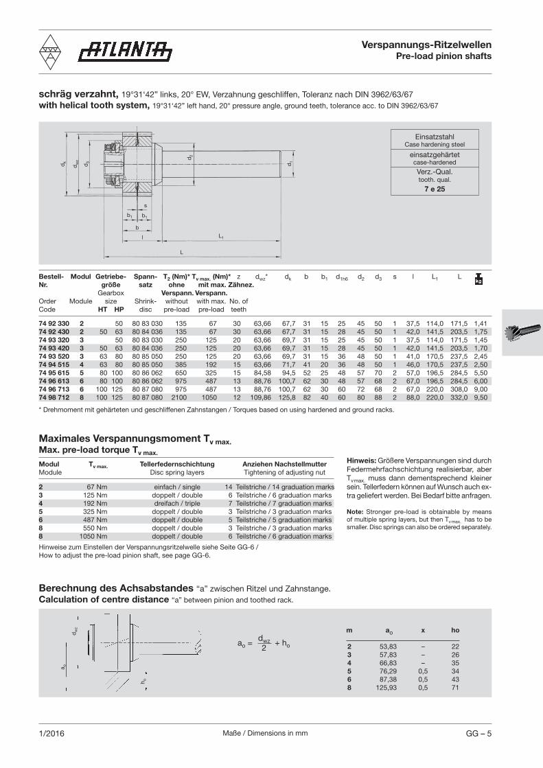
schräg verzahnt, 19°31‘42” links, 20° EW, Verzahnung geschliffen, Toleranz nach DIN 3962/63/67with helical tooth system, 19°31‘42” left hand, 20° pressure angle, ground teeth, tolerance acc. to DIN 3962/63/67
Maximales Verspannungsmoment Tv max. Max. pre-load torque Tv max.
Modul Tv max. Tellerfedernschichtung Anziehen Nachstellmutter Module Disc spring layers Tightening of adjusting nut
2 67 Nm einfach / single 14 Teilstriche / 14 graduation marks3 125 Nm doppelt / double 6 Teilstriche / 6 graduation marks4 192 Nm dreifach / triple 7 Teilstriche / 7 graduation marks5 325 Nm doppelt / double 3 Teilstriche / 3 graduation marks6 487 Nm doppelt / double 5 Teilstriche / 5 graduation marks8 550 Nm doppelt / double 3 Teilstriche / 3 graduation marks8 1050 Nm doppelt / double 6 Teilstriche / 6 graduation marks
Hinweis: Größere Verspannungen sind durch Federmehrfachschichtung realisierbar, aber Tv max. muss dann dementsprechend kleiner sein. Tellerfedern können auf Wunsch auch ex-tra geliefert werden. Bei Bedarf bitte anfragen.
Note: Stronger pre-load is obtainable by means of multiple spring layers, but then Tv max. has to be smaller. Disc springs can also be ordered separately.
Berechnung des Achsabstandes “a” zwischen Ritzel und Zahnstange.Calculation of centre distance “a” between pinion and toothed rack.
m ao x ho 2 53,83 – 22 3 57,83 – 26 4 66,83 – 35 5 76,29 0,5 34 6 87,38 0,5 43 8 125,93 0,5 71
Verspannungs-RitzelwellenPre-load pinion shafts
dw
z
b
dk
d3
d2
d1
s
b1 b1
l
L
L1
dw
z
h o
a o
Bestell- Modul Getriebe- Spann- T2 (Nm)* Tv max. (Nm)* z dwz* dk b b1 d1h6 d2 d3 s l L1 L Nr. größe satz ohne mit max. Zähnez. Gearbox Verspann. Verspann.Order Module size Shrink- without with max. No. of Code HT HP disc pre-load pre-load teeth
74 92 330 2 50 80 83 030 135 67 30 63,66 67,7 31 15 25 45 50 1 37,5 114,0 171,5 1,4174 92 430 2 50 63 80 84 036 135 67 30 63,66 67,7 31 15 28 45 50 1 42,0 141,5 203,5 1,7574 93 320 3 50 80 83 030 250 125 20 63,66 69,7 31 15 25 45 50 1 37,5 114,0 171,5 1,4574 93 420 3 50 63 80 84 036 250 125 20 63,66 69,7 31 15 28 45 50 1 42,0 141,5 203,5 1,7074 93 520 3 63 80 80 85 050 250 125 20 63,66 69,7 31 15 36 48 50 1 41,0 170,5 237,5 2,4574 94 515 4 63 80 80 85 050 385 192 15 63,66 71,7 41 20 36 48 50 1 46,0 170,5 237,5 2,5074 95 615 5 80 100 80 86 062 650 325 15 84,58 94,5 52 25 48 57 70 2 57,0 196,5 284,5 5,5074 96 613 6 80 100 80 86 062 975 487 13 88,76 100,7 62 30 48 57 68 2 67,0 196,5 284,5 6,0074 96 713 6 100 125 80 87 080 975 487 13 88,76 100,7 62 30 60 72 68 2 67,0 220,0 308,0 9,0074 98 712 8 100 125 80 87 080 2100 1050 12 109,86 125,8 82 40 60 80 88 2 88,0 220,0 332,0 9,50
* Drehmoment mit gehärteten und geschliffenen Zahnstangen / Torques based on using hardened and ground racks.
Hinweise zum Einstellen der Verspannungsritzelwelle siehe Seite GG-6 /How to adjust the pre-load pinion shaft, see page GG-6.
ao = dwz2
+ ho
EinsatzstahlCase hardening steel
einsatzgehärtetcase-hardened
Verz.-Qual.tooth. qual.
7 e 25

Maße / Dimensions in mmGG – 6 1/2013
FunktionsbeschreibungVerspannungs-Ritzelwellen bestehen aus einer Abtriebswelle, einem schrägverzahnten Zahnradpaar und einer Verspannungs-einheit. Das Zahnradpaar ist mit einem axialen Abstand, s = 1 mm (m = 2...4) und s = 2 mm (m = 5...8), gemeinsam gefertigt. Durch Verminderung dieses Abstandes (axiale Verschiebung des äußeren Rades) zwischen den Zahnrädern wird beim Zahn-eingriff mit der Zahnstange, das Zahnspiel reduziert bzw. die Verspannung eingeleitet. Über die Verspannungseinheit kann ein definiertes Verspannungsmoment zwischen Zahnstange und Zahnradpaar erzeugt werden.
Einstellanleitung Die Verspannungseinheit besteht aus:• einer Nachstellmutter, die über ein Siche -
rungsblech und einer Senkschraube gegen Verdrehen gesichert ist
• einem geschichteten Tellerfedernpaket • einer Druckscheibe. Auf der Rückseite der Druckscheibe sind 24, bei m = 2...4 bzw. 12 bei m = 5...8, und der Nachstellmutter 4 Markierungen (Teilstriche) eingeprägt. 1. Optimales Tragbild mit nicht verspann-
ter Ritzelwelle ermitteln. Dazu ist die Ritzelwelle mit Spalt „s“ (siehe oben) zu montieren.
2. Dabei sollte Flankenspiel zwischen Zahnstange und Radpaar < 0,1 mm sein.
3. Nachstellmutter anziehen (Senkschrau-be lösen) bis kein Zahnspiel mehr vorhanden ist, beide Flanken des Rad-paares sollten wechselseitig anliegen. Dies kann durch Abtasten der Zahn-flanken mit einer Messuhr nachgeprüft werden.
4. Definierte Verspannung (Tv) kann ein-geleitet werden, indem die Nachstell-mutter über eine bestimmte Anzahl der Teilstriche (TS) angezogen wird (siehe Einstelldiagramm).
Das Verspannungsmoment „Tv“ ist das Drehmoment das ein spielfreies Positionieren des Zahnstangentriebes gewährleistet. Das übertragbare Drehmoment außerhalb der Positionierstellen „T2max.“, kann nach der untenstehenden Formel ermittelt werden:
T2 max. = T2 - Tv Wenn: Tv max. = T2 max. dann ist der Antrieb über die gesamte Fahrstrecke spielfrei. Achtung: Die Verspannung wird im montierten Zustand einge-stellt, dazu muss die Stirnseite der Ritzelwelle zugänglich sein.Zum Verspannen empfehlen wir den Einstellschlüssel (Seite GG-8).
Schmierempfehlungen Filzzahnrad oder Gleitpinsel mit Fettzufuhr über elektronisch gesteuerte Schmierbuchse. Durch die Elastizität der Zähne kön-nen Filzräder auch dann eingesetzt werden wenn ein maximaler Spielausgleich stattfindet. Schmiermittel im Servo-Katalog, Seite ZE-2 bis ZE-9.
Description of operationPre-load pinion shafts consist of an output shaft, a helical split pinion and a pre-load unit. The split pinion is manufactured as a unit with an axial distance of s = 1 mm (m = 2...4) and s = 2 mm (m = 5...8). By reducing the distance between the pinions (axial displacement of the outer pinion) the backlash is reduced and pre-load initiated when teeth are in mesh with the rack. A defined pre-load torque between rack and split pinion can be produced by means of the pre-load unit.
Verspannungs-Ritzelwelle / Pre-load Pinion Shaft Funktionsbeschreibung und Einstellanleitung
Description of Operation and Adjusting Instructions
s m
m o
hne
Vors
pan
nung
/ w
ithou
t p
re-l
oad
1TS
Adjusting instructionsThe pre-load unit consists of:• an adjusting nut which is secured
against turning by means of a safety washer and a countersunk screw
• a disc spring assembly• a thrust plate.The reverse side of the thrust plate is pro-vided with 24 marks at m = 2...4 and 12 at m = 5...8, and the adjusting nut with 4 marks (graduations).1. Determine the optimal tooth contact
with non-preloaded split-pinion shaft. For this purpose mount the pinion shaft with gap „s“ (see above).
2. The backlash between rack and split pinion should be < 0.1 mm.
3. Tighten the adjusting nut (loosen the countersunk screw) until no backlash remains. The two flanks of the split pinion should be in mutual contact. This can be checked by scanning the tooth flanks with a dial indicator.
4. The specified degree of pre-load (Tv) can be produced by turning the adjust-ing nut by a definite number of gradua-tion marks (TS) (see adjusting diagram).
The pre-load torque „Tv“ is the torque which ensures backlash-free positioning of the rack and pinion drive. The transmissible torque outside the positioning points „T2max.“ can be determined according to the following formula:
T2max. = T2 - TvIf: Tv max. = T2 max. the drive is free from play throughout the travelling distance.Attention: The pre-load is adjusted in assembled condition; therefore the front side of the pinion shaft must be accessible.To adjust the pre-load, we recommend our adjusting wrench (page GG-8).
Lubrication recommendationsFelt gearwheel or sliding brush with grease supply by means of an electronically controlled lubricator. Due to the elasticity of the teeth, the felt gearwheels can be used even with maximum backlash compensation.Lubricants see Servo-Catalogue page ZE-2 to ZE-9.

Maße / Dimensions in mm GG – 71/2013
Verspannungs-Ritzelwelle / Pre-load Pinion Shaft Einstelldiagramm Verspannungsmoment Tv
Adjusting Diagram for Pre-load Torque Tv

Maße / Dimensions in mmGG – 8 1/2013
Verspannungs-Ritzelwelle – Einstellschlüssel Pre-load Pinion Shaft – Adjusting wrench
74 90 001 74 92 330 19 8 12 10,0 2,5 37 50 27,5 0,113 74 92 430 74 93 320 74 93 420 74 93 520 74 94 515 74 90 002 74 95 615 19 8 12 12,5 4,0 50 74 34,0 0,338 74 96 613 74 96 713
74 90 003 74 98 612 22 9 12 13,0 6,0 67 96 40,0 0,625 74 98 712
Sicherungsschraube der NachstellmutterLocking screw of the adjusting nut
HaltemagnetHolding magnet
StahlSteel
Attention:
Apply the adjusting wrench by hand.
Be careful to position the adjusting wrench correctly in relation to the locking screw.
Pins must engage the adjusting nut (do not tap).
The holding magnet holds the adjusting wrench in position.
Loosen the locking screw by the adjusting nut.
Mind the functional characteristics and adjusting instructions for making the adjustment.
Use the Allen wrench with width over flats SWi or the fork wrench with width over flats SWa for turning the adjusting wrench.
Tighten the locking screw by the adjusting nut.
Achtung:
Einstellschlüssel von Hand aufsetzen.
Stellung des Einstellschlüssels zur Sicherungsschraube beachten.
Stifte müssen in die Nachstellmutter eingreifen (nicht klopfen).
Haltemagnet hält den Einstellschlüssel in Position.
Sicherungsschraube an der Nachstellmutter lösen.
Zum Einstellen, Funktionsbeschreibung und Einstellanleitung der Verspannungs-Ritzelwelle beachten.
Zum Drehen des Einstellschlüssels, den Innensechskant SWi oder den Aussensechskant SWa benutzen.
Sicherungsschraube an der Nachstellmutter anziehen.
Bestell-Nr. Verspannungs- SWa la SWi li ds Lk d L RitzelwelleOrder code Pre-load T2 max pinion shafts