geotech environmental control module
TRANSCRIPT

Rev 06/06/2017 Part # 16110163
Geotech Environmental
Control Module
Installation and Operation Manual

0

1
Table of Contents
Section 1: System Description ................................................................................................4
Overview ............................................................................................................................................ 4 How the GECM works ........................................................................................................................ 4 General Description ........................................................................................................................... 4
Section 2: System Installation .................................................................................................6
Inspection .......................................................................................................................................... 6 GECM Panel Installation .................................................................................................................... 6 Input Power Guidelines ...................................................................................................................... 6 Access Ports and Conduit Hubs ......................................................................................................... 6 Install Chassis Ground ....................................................................................................................... 6 Install IS Ground ................................................................................................................................ 6 Wire Main Power................................................................................................................................ 6 Install Incoming Power to Motor Starters ............................................................................................ 7 Installing Blower Thermals ................................................................................................................. 7 Installing an 115VAC/230VAC to 12VDC Power Supply .................................................................... 7 Installing and implementing a Dry Contact ......................................................................................... 7 IS Wiring Installation Guidelines ......................................................................................................... 8 Wiring Reservoir, Tankfull, Sump and Water Pump Probes ............................................................... 8 Using a MeLabs Field Programmer .................................................................................................... 9
Section 3: System Operation ................................................................................................. 10
User Interface .................................................................................................................................. 10
Section 4: Display Definitions ............................................................................................... 13
SDFS/PSCAV Displays – ................................................................................................................. 13 Multiple SDFS/PSCAV Systems ...................................................................................................... 13 Additional Messages for Multiple SDFS/PSCAV Systems ................................................................ 14 WTDP Displays ................................................................................................................................ 14 LOPRO Displays - ............................................................................................................................ 15 SVE Displays ................................................................................................................................... 15 SVE with Transfer Pump and 3-position probe Displays – ............................................................... 15 SVE with Sparge Displays ............................................................................................................... 16 Sparge Displays ............................................................................................................................... 16 Telemetry Messages on GECM Display - ........................................................................................ 17
Section 5: Troubleshooting Guide ........................................................................................ 18
Section 6: System Specifications ......................................................................................... 21
Section 7: Parts and Accessories ......................................................................................... 22
Appendix A – Customer and Device Information ................................................................ 22
Appendix B - Glossary of Acronyms .................................................................................... 24
The Warranty ........................................................................................................................... 26

2
3
DOCUMENTATION CONVENTIONS
This manual uses the following conventions to present information:
An exclamation point icon indicates a WARNING of a situation or condition that could lead to personal injury or death. You should not proceed until you read and
thoroughly understand the WARNING message.
A raised hand icon indicates CAUTION information that relates to a situation or condition that could lead to equipment malfunction or damage. You should not proceed until you read and thoroughly understand the CAUTION message.
A note icon indicates NOTE information. Notes provide additional or supplementary information about an activity or concept.

4
Section 1: System Description Overview The Geotech Environmental Control Module (GECM) is a microprocessor-based industrial control panel for the operation of remediation and industrial equipment including, but not limited to Geotech branded equipment. The GECM is designed for installation in an unclassified location, with Intrinsically Safe (IS) circuit extensions into hazardous (classified) locations. The GECM has also been designed for ease of use and installation; a single panel can accommodate a wide variety of equipment control needs. A standard panel is capable of controlling up to eight devices from 24 IS probe inputs. Devices can vary from small signal relays to 75 HP motor starters. A panel can be easily expanded to accommodate up to 32 additional outputs and 96 additional IS probe inputs. This equipment should be installed in accordance with NEC NFPA 70. How the GECM works The GECM uses highly flexible microprocessor based electronics to provide a wide spectrum of capabilities that range from basic motor control to complex and sophisticated multi-panel networking. This built in versatility allows the GECM to be configured to match the unique requirements of a vast variety of industrial and remediation equipment control. Basic motor control is achieved by use of magnetic motor starters. All standard motor starters have built in over current protection. More sophisticated motor control techniques can be achieved by use of a Variable Frequency Drive (VFD) that can interface directly with the GECM. General Description The GECM has a wide variety of capabilities for automatically controlling electrical environmental remediation equipment. Site-specific needs can be met on an individual basis from a single flexible platform. Panels include a varied configuration to operate the following equipment:
Geotech Small Diameter Filter Scavenger (SDFS) with 12VDC product pump
Geotech Small Diameter Probe Scavenger (PSCAV) with 12VDC product pump
Water Table Depression Pumps (WTDP) up to 75 HP
LOPRO II and III Air Stripper blowers up to 75 HP
Soil Vapor Extractor (SVE) blowers up to 75 HP
Air Sparge Compressors up to 75 HP
Transfer Pumps up to 75 HP
Equipment up to 75 HP
Figure 1-1: Example of a GECM with SVE-HAZMAT system

5
Features and Options The GECM is available with a host of options to accomidate site needs and customer preference.
All components are housed in an easy to install weatherproof NEMA 4X (IP66) enclosure.
A bright 16 x 2 character Vacuum Fluorescent Display (VFD) shows users exactly what is happening with each individual component within the system. For example, a probe’s float position or an output device’s ON/OFF status can easily be viewed on the display, day or night.
A 4-button keypad can be used to scroll through menus and status displays.
Hand-Off-Auto (HOA) switch controls for direct control over individual system devices.
System run lights and alarm lights, mounted on the panel itself or mounted atop the panel so that a GECM’s operational status can be seen from a distance.
Optional, pre-wired circular connectors are available for probe connections to make installation fast and simple.
The design incorporates circuitry for wiring extensions into hazardous (classified) locations.
For lower, short-circuit rated systems, fused disconnect options are available.
Electro-mechanical runtime meters to track and monitor device active runtime.
ON/OFF timers for managing time-sensitive systems in community environments.
Remote monitoring of system faults and status via SMS (text message) telemetry, includes battery backup for power outage alerts.
In addition, each GECM will come with an Installation and Operation Manual containing device specifications unique to the unit’s application. A GECM Field Wiring Diagram is also included with each manual. The GECM Field Wiring Diagram illustrates the internal layout of the GECM panel and also contains wiring information pertinent to device installation and troublshooting.

6
Section 2: System Installation Inspection Inspect all components for physical damage. Installing and operating damaged equipment is dangerous and should not be performed. Verify that all components have arrived as per the Sales Order or packing list. GECM Panel Installation Even though the GECM electronics are enclosed within a NEMA 4 rated weatherproof box, it is advised that you place your GECM within a sheltered area, protecting the unit from direct exposure to water and sunlight. Input Power Guidelines All wiring must be carried out by a qualified electrician and be in accordance with state and local codes. Conduit runs must conform to current U.S. National Electrical Code (NEC). Do not run any power wires within 2” (5 cm) of intrinsically safe (IS) wires or terminals (NEC Article 508 for relevant codes). All equipment and controls are to be installed in accordance with Article 430 and 504 of the NEC. See also the GECM Field Wiring Diagram for specific connections to the back panel and Printed Circuit Board (PCB). Geotech provides a detailed Field Wiring Diagram with every GECM built. Copies of these diagrams can be obtained from Geotech when needed. Access Ports and Conduit Hubs To facilitate wiring, Geotech installs access ports and conduit hubs to the GECM enclosures that are hard mounted to the system being manufactured, i.e., a LOPRO or SVE. A GECM enclosure will not have this wiring option when built and shipped separately. When installing a GECM enclosure ensure that ports installed for IS wiring are placed within the upper sides of the enclosure (close to the PCB) and that all conduit hubs for main power, blowers, and pumps are installed along the bottom. To maintain the NEMA 4 weatherproof characteristics of your panel use weatherproof conduit hubs. Install Chassis Ground Before beginning the panel hookup procedures, run a wire from the bottom ground lug on the GECM back panel to a good earth ground, i.e., the circuit breaker panel enclosure. Install IS Ground Connect IS ground wires to the upper ground lug on the GECM back panel. Wire Main Power The GECM can be built to operate with 115VAC/1PH, 230VAC/1PH or 3PH (or a combination of both 1PH and 3PH), or 460VAC/3PH. Incoming power leads are normally connected to either a terminal strip or fused disconnect labeled L1 and L2 (single phase applications) or L1, L2 and L3 (three phase

7
applications). When a fused disconnect is installed for three phase power to the motor starters, Geotech will complete all wiring on the GECM side of the components. The following wiring descriptions are for standard GECM configurations. In conjunction with the GECM Field Wiring Diagram, always refer to the system diagrams and labels found within the device User Manuals, including those diagrams provided with custom built panels. Install Incoming Power to Motor Starters Most motor driven devices controlled by the GECM (LOPRO, SVE, Sparge, WTDP, Transfer Pump) require the use of a motor starter. Motor starters are installed to the back panel when the GECM is built. Run main power for the individual motor starters through the bottom of the enclosure. Each motor starter is labeled for the device they support. Refer to the wiring diagram for specific terminal connections. Attach all ground wires to the ground lug at the bottom of the panel.
Installing Blower Thermals The GECM incorporates thermal overload protection for those motors which are equipped. When a motor manufacturer provides thermal overload protection there will typically be two additional wires within the motor’s electrical box labeled “J”. These wires will run through the same port used for the motor power and are connected to the intrinsically safe PCB terminal, normally labeled THERMALS. Installing an 115VAC/230VAC to 12VDC Power Supply Geotech provides 115VAC and 230VAC Power Supply’s which are needed to operate the 12VDC product pump motors contained within SDFS and PSCAV systems. Power requirements and control are dependent upon the GECM and are probe activated. The GECM back panel will contain labeled relays with terminal strips (labeled PRODUCT PUMP) from which hot leads will be connected. These leads will then go to a designated power supply box and be converted to 12VDC for product pump operation.
Use the GECM Field Wiring Diagram to complete all wire connections between the GECM and the power supply box. Installing and implementing a Dry Contact The GECM is equipped with a Dry Contact which will change state when the GECM encounter’s a fault condition. This is useful if there is an influent or effluent system that is not controlled directly by the
DO NOT run power wires within two inches of IS wiring or terminals.
Power supply boxes should be installed as near to the well as possible to
reduce DC line loss in the cable connecting the product pump to the box.

8
GECM but is part of the process flow and needs to be alerted when the GECM’s devices shutdown Example of this includes an influent pump for a LOPRO Air Stripper system, or an air sparge system that can not run if the SVE has shutdown. The Dry Contact relay is connected to a 3-position terminal strip labeled NO (normally-open), NC (normally-closed), C (common); the user may choose if NO or NC is be suited for their application. See Figure 2-1 for example of a standard dry contact configuration. IS Wiring Installation Guidelines The GECM incorporates circuitry for IS circuit extensions into hazardous locations. All IS wiring must be at least 2” (5 cm) from all other non-IS wiring. All IS wire terminations must be securely tightened in screw terminals on the GECM PCB. It is recommended that you use only Geotech supplied probe cable (P/N ORS418005) for IS wiring and Geotech supplied IS float probes with jacketed cable. The maximum length of a Geotech probe cable that can be connected to IS circuitry is 500’ (152 m). Wiring Reservoir, Tankfull, Sump and Water Pump Probes These devices are wired to designated ports on the GECM PCB and are defined on the GECM Field Wiring Diagram provided. Wiring diagrams for the various equipment probes and devices can be found within the user manuals for the device they support. Common probes built by Geotech support the operation of the following devices: Reservoir Probe SDFS Water Pump Probe WTDP Motors and Transfer Pumps Tankfull Probe SDFS and PSCAV Sump Probe LOPRO II and III Air Strippers 3 Position Probe SVE and Custom Devices
Figure 2-2: Diagram of IS input terminal on GECM PCB
Figure 2-1: Diagram of Dry Contact

9
Using a MeLabs Field Programmer If for any reason the GECM needs to undergo a firmware update, Geotech will provide the new software on a MeLabs Field Programmer. Follow the instructions below to successfully update the GECM.
1. Verify SD card is properly inserted into card slot. Press the back of the SD card to ensure it is inserted as far as it will go. There will be a click to release or lock the card in.
* Do this a couple time to verify the card is in proper position. A small portion of the card will stick out from the end of the programmer housing.
2. Open GECM door and inner panel to gain access to controller board. 3. Remove the PCB Enclosure using a 5/16” wrench/nut driver or #2 Philips screwdriver. 4. At the top near the middle will be a 6 pin jack
* Black phone jack like housing. 5. Plug the cable of field programmer into the jack. 6. With power applied to the unit the LED will be lit up GREEN. 7. Press the program button on the face of the field programmer. 8. During programming LED will be a solid RED.
*If LED Flashes RED call Geotech at 1-800-833-7958 or 303-320-4764. 9. When programming is completed the LED will return to a solid GREEN. 10. Remove cable from controller board, reinstall the PCB enclosure and close up the GECM.
Unit is now ready for use.

10
Section 3: System Operation User Interface Display & Keypad Each GECM is equipped with a 16 x 2 character, extended temperature Display. Information regarding device status, probe levels (when applicable), and any alarm conditions are displayed. In an alarm condition, the display readout will show the most recent fault which halted system operation. Once fault condition is corrected the red RESET button can be pressed to resume system operation. A 4-button keypad enables menu and scroll views on the Display for all systems. Continued scrolling will provide access to various information and diagnostics screens and allows for the telemetry module to be configured and enabled/disabled. The keypad will provide an indepth view of how the system is operating. Custom panel application displays may vary according to customer requirements. Any custom display definitions will be included within the device specific GECM manual. Equipment status and alarm condition displays are specific to each panel and its required control application. A list of standard displays and their definitions can be found in Section 4: Display Definitions of this manual. A description of the abbreviated display responses/acronymns can be referenced in Appendix B. HOA Switches & Indicator Lights In addition to a Display and 4-button keypad, the GECM will provide HAND/OFF/AUTO (HOA) switches that control each device. HAND has a spring return and must be held in position to directly power the device, regardless of switch input. OFF will shutdown all controls and automation to the specific device. The GECM will remain powered on. AUTO latches the hardware and will run the device autonomously with inputs from various switches. AUTO should be used normally, but HAND may be used to verify device operation, i.e.: “bumping” the device motor. To “bump” a device’s motor when the GECM is in a fault condition, adjust device’s HOA switch to OFF position, then press the RESET button. HAND will now be active and will help to ensure devices are still in operational condition. In the case of a fault condition where both devices are powered down, AUTO will provide no device power.
Figure 4-1: Example of a
HAND/OFF/AUTO (HOA) Switch

11
RESET Button Each GECM is designed to automatically shutdown the system and associate devices whenever a fault condition occurs. Once the fault or condition has been corrected the system can be easily turned back on by pressing the red RESET button. This will clear the firmware fault and automatically turn on any equipment still set to AUTO. If you do not want a given device to turn back on, then set the appropriate switch to OFF prior to using the RESET button. Momentarily pressing the RESET button may also restore a blank or faulty display. However, contact Geotech should display problems occur that will not clear up with this method. Telemetry Enable/Disable and Configuration Stay in touch with deployed remediation systems via SMS (text message) Telemetry embedded within any GECMs. Systems equipped with Telemetry are optimized for simple send-and-receive queries that make remote sites convenient to monitor. Each control panel can be programmed with up to 5 cell-phone numbers. When the system enters into a fault condition, the programmed numbers will be notified through text message. POWER ON and POWER OUTAGE alerts are facilitated by an incorporated short-life battery backup. In addition, the control panel may be queried for operating status updates. Custom queries and configurations are available depending on site requirements. The unit must be powered on and the specified antenna connected to facilitate successful communication. Systems are connected through a cellular network and accounts are managed through Geotech. Costs will depend on size of systems, frequency of alert conditions and commands, and location relative to cellular service. Antenna types will depend on location and proximity to cell towers. A list of standard messages and their definitions can be found in Section 4: Display Definitions of this manual. A description of the abbreviated display responses/acronymns can be referenced in Appendix B. Setup Steps:
1. From the MAIN screen, place all HOA switches into the OFF position. 2. Press the RESET button to clear the GECM and its display of any fault conditions. 3. Simultaneously hold the LEFT & RIGHT arrow buttons on the 4-button keypad to enter into the
Factory Setup menu. 4. Use the flow chart (Figure 4.2) to enable and configure, or disable telemetry settings.
Once configured, using the UP/DOWN arrows on the keypad will display the programmed phone numbers.
Disabling Telemetry through the Factory Setup menu does not affect the cellular service plan, but is rather useful when installing/testing/troubleshooting Please contact your Geotech Customer Service Representative for all cellular plan service details.

12
Figure 4-2: Telemetry Enable/Configure User Interface flow chart

13
Section 4: Display Definitions The following pages describe status and fault displays used in a standard GECM configuration. Status and fault displays generated for unique GECM/system configurations will be further detailed within the customer’s Logic Description and individual device manual. The following displays are common to the equipments shown. System status, condition and fault messages are shown on Line 1 of the display preceded by the system name and unit # (when there are two or more of the same device). A device status will then be displayed on Line 2. Fault and condition messages will require a system inspection and that the device be RESET at the GECM. Use this section, in conjunction with the individual device manual, to troubleshoot any fault or condition messages.
SDFS/PSCAV Displays – Line 1 messages: HAND:Px H2Ox ORx
AUTO:Px H2Ox ORx
AUTO: TANKFULL (condition)
AUTO: H2O IN RES (fault - SDFS only)
AUTO: OVERRIDE (fault)
AUTO:PROBE FAULT (fault)
AUTO: AUX ALARM (fault)
Line 2 messages:
PRODnnnn H2Onnnn
Where x =H (high), M (middle), or L (low) nnnn = ON, OFF or HAND Multiple SDFS/PSCAV Systems - Line 1 messages:
SDFS SYSTEM # or PSCAV SYSTEM #
SDFS#: TANKFULL or PSCV#: TANKFULL (condition)
SDFS#:H2O IN RES (fault - SDFS only)
SDFS#: OVERRIDE or PSCV#: OVERRIDE (fault)
SDFS#:PROBEFAULT or PSCV#:PROBEFAULT (fault)
SDFS#: AUX ALARM or PSCV#: AUX ALARM (fault)
A GECM controlling more than one system configuration will take
advantage of up/down arrow buttons to review individual system displays.

14
Line 2 messages:
PRODnnnn H2Onnnn
Where # =1, 2, 3 or 4 (SDFS/PSCAV number) nnnn = ON, OFF or HAND
Additional Messages for Multiple SDFS/PSCAV Systems -
SDFS#: LEVELS or PSCAV #: LEVELS (fault)
OVERRIDE or OVERRIDE
SDFS#: LEVELS or PSCAV #: LEVELS (fault)
PROBE FAULT or PROBE FAULT
SDFS#: LEVELS or PSCAV #: LEVELS
Px H2Ox ORx or Px H2Ox ORx
Where # = 1, 2, 3 or 4 (SDFS/PSCAV number) x = H (high), M (middle), or L (low) WTDP Displays – Line 1 messages:
WTDP: H2Ox ORx
WTDP: OVERRIDE (fault)
WTDP: PROBEFAULT (fault)
WTDP: AUX ALARM (fault)
Line 2 messages: WATER PUMP nnnn
Where x =H (high), M (middle), or L (low) nnnn = ON, OFF or HAND
15
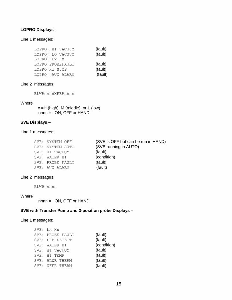
LOPRO Displays - Line 1 messages:
LOPRO: HI VACUUM (fault)
LOPRO: LO VACUUM (fault) LOPRO: Lx Hx
LOPRO:PROBEFAULT (fault)
LOPRO:HI SUMP (fault)
LOPRO: AUX ALARM (fault)
Line 2 messages: BLWRnnnnXFERnnnn
Where x =H (high), M (middle), or L (low) nnnn = ON, OFF or HAND SVE Displays – Line 1 messages:
SVE: SYSTEM OFF (SVE is OFF but can be run in HAND)
SVE: SYSTEM AUTO (SVE running in AUTO)
SVE: HI VACUUM (fault)
SVE: WATER HI (condition)
SVE: PROBE FAULT (fault)
SVE: AUX ALARM (fault)
Line 2 messages: BLWR nnnn
Where nnnn = ON, OFF or HAND SVE with Transfer Pump and 3-position probe Displays – Line 1 messages:
SVE: Lx Hx
SVE: PROBE FAULT (fault)
SVE: PRB DETECT (fault)
SVE: WATER HI (condition)
SVE: HI VACUUM (fault)
SVE: HI TEMP (fault)
SVE: BLWR THERM (fault)
SVE: XFER THERM (fault)

16
SVE: TANKFULL (fault)
SVE: AUX ALARM (fault)
Line 2 messages: BLWRnnnnXFERnnnn
Where x =H (high), M (middle), or L (low) nnnn = ON, OFF or HAND SVE with Sparge Displays – Line 1 messages:
SVE: SYSTEM OFF (SVE and Sparge are OFF, either unit can be run in HAND)
SVE: SYSTEM AUTO (SVE is running in AUTO – with or without Sparge)
SVE: HI VACUUM (fault)
SVE: WATER HI (condition)
SVE: PROBE FAULT (fault)
SVE: AUX ALARM (fault)
Line 2 messages: BLWRnnnnSPRGnnnn
Where nnnn = ON, OFF or HAND
Sparge Displays – Line 1 messages:
SPRG:SYSTEM OFF (Sparge is OFF but can be run in HAND)
SPRG:SYSTEM AUTO (Sparge running in AUTO)
SPRG:HI PRESSURE (fault)
SPRG:HI TEMP (fault)
SPRG:DRY CONTACT (fault)
SPRG: AUX ALARM (fault)
Line 2 messages: BLOWER nnnn
Where nnnn = ON, OFF or HAND HAND indicates that a device is in manual operation. Once corrected, the RESET button must be pressed to clear any occurring faults or conditions.

17
Telemetry Messages on GECM Display - Each GECM unit equipped and enabled with Telemetry will send a text message to the programmed phone numbers for every condition and fault for the specific device listed in the previous pages. The battery backup will send an additional “Power On” and “Power Outage” text message to inform the user of power status. Additional display and details correlating to the Telemetry package are listed below. Custom units may have varying Display and Telemetry alerts. Startup sequence:
Waiting on Modem
Startup
This indicates the modem is going through initiation routines and connecting to the cellular network. This will happen every time the system is powered on, and when telemetry is enabled through the keypad.
Sending SMS alert:
Sending msg #--
To phone [x] of [X]
This indicates the modem is currently sending a message to programmed phone numbers. Text messages correspond to the device and display definitions listed in the previous pages.
Receiving SMS Query:
Query [x] match
This indicates the modem has successfully received a query text message. This screen is followed by the “Sending SMS alert” display which is responding to the query.
System’s response to text message “STATUS?” (case sensitive):
System Standby System On, all HOA switches in the “OFF” position
System Running One or all HOA switches in the “ON” position
System In Alarm System experiencing fault, see last message received
If GECM is not responding to query messages, check that power is ON and that the antenna is attached. Damaged antennas should be replaced as soon as possible.

18
Section 5: Troubleshooting Guide Use this section, in conjunction with Section 4: Display Definitions, to troubleshoot any system problems.
No Apparent Power to the GECM –
Check all incoming wire connections.
Check fuses and breakers at power source, refer to wiring diagram. (Fuses can also be found on the GECM PCB. These can blow from a voltage spike or incorrect voltage applied to the GECM. Allow a Geotech technician to service these fuses.)
No Display or non-sensicle alpha-numerics –
Press RESET button.
Fuse is blown in the GECM PCB or faulty electronics. Return to Geotech for service. Blower Will Not Run –
Check device status on GECM display.
Check for blown fuses.
Check wire connections between device and GECM.
Check motor for over-heating, press RESET button on motor starter if necessary.
HI or LO vacuum switches preventing unit from starting up. Transfer Pump Will Not Run –
Check device status on GECM display.
Check for blown fuses.
Check wire connections between device and GECM.
Check motor for over-heating, press RESET button on motor starter if necessary.
Check sump and/or three position probe floats and verify that nothing is obstructing their movement.
Check probe wiring to GECM.
Pump may have over-amped due to obstruction in flow line. Clear line and restart pump. Transfer Pump Will Not Shut Off –
Check sump and/or three position probe floats and verify that nothing is obstructing their movement.
Check probe wiring to GECM.
The RESET button must be depressed to clear a system fault or condition. This will also automatically restart any devices still set to AUTO.

19
High Vacuum Message or Switch Not Working –
Verify wiring connections between GECM and switch.
See Troubleshooting Procedures for HI Vacuum conditions in the LOPRO or SVE User Manual. Low Vacuum Message or Switch Not Working –
Verify wiring connections between GECM and switch.
See Troubleshooting Procedures for LO Vacuum conditions in the LOPRO or SVE User Manual.
High Temp Message –
Verify wiring connections between GECM and switch.
See Troubleshooting Procedures in Sparge User Manual. High Pressure Message –
Verify wiring connections between GECM and switch.
See Troubleshooting Procedures in Sparge User Manual. Product Pump Will Not Run –
Check device status on GECM display.
Check for blown fuses (especially at power supply).
Check for a bad relay connection between GECM and power supply.
Check wire connections between device and GECM.
Check reservoir probe floats and verify that nothing is obstructing their movement.
Check that hydrocarbons are still present in well and that the SDFS/PSCAV unit is correctly positioned on the hydrocarbon/water interface.
Check probe wiring to GECM. Water Pump Will Not Run –
Check device status on GECM display.
Check for blown fuses.
Check wire connections between device and GECM.
Check reservoir probe floats and verify that nothing is obstructing their movement.
Check water level probe floats (when separate water pump in use).
Check that hydrocarbons are still present in well and that the SDFS/PSCAV unit is correctly positioned on the hydrocarbon/water interface.
Check probe wiring to GECM.
Pump may have over-amped due to obstruction, dry running, or damage. Inspect pump and flow route.
Dry Contact Message –
Check for circuit conflicts between GECM and other devices or switches.
Have the logic statements and operation of any custom built devices checked.

20
Probe Fault –
This error will occur when the HIHI float is in the up position and the HI/LO float is in the down position. Check for free movement on all floats.
A switch wire may have become disconnected or broken. Override Message (SDFS/PSCAV) –
Water override float is down and the HI/LO float is up (PSCAV). Check for free movement on all floats.
Water override float is down and the intake float cartridge is up (SDFS). Check for free movement on all floats.
A switch wire may have become disconnected or broken. H2O In RES Message (SDFS) -
Water in reservoir. Set Product Pump switch to hand to clear reservoir of water.
Intake cartridge screen needs to be re-primed to prevent water from entering the screen.
Unit is being placed below the intake cartridge travel. Tankfull Message –
Product recovery tank is full.
A switch wire may have become disconnected or broken. Auxiliary (AUX) Alarm Message -
External system (for example: an influent pump on LOPRO) has sent a dry contact message to the GECM, instructing the GECM to shutdown. Ensure external system’s faults are cleared in order to resume normal operation.
A wire may have become disconnected or broken, check wiring diagram.

21
Section 6: System Specifications Electrical: Operating Power: 10 Watts Input Voltage: 115VAC (1PH), 230VAC (1PH and 3PH), or 460VAC (3PH) (See individual device wiring diagrams and manuals for detailed electrical specifications) Environmental Conditions: 0-104º F (-17.8 - 40º C) A normal barometric pressure of one atmosphere. (Enclosure heaters and cooling fans available can extend the temperature range to -30 to 110° F (-34 to 43° C) Mechanical: Main enclosure: NEMA 4X (IP66) Enclosure material: Fiberglass External height:18” (45.7 cm) External width:16” (40.6 cm) External depth:10” (25 cm) Weight: 15 to 45 lbs (6.8 to 20 kgs) (depending on installed options) Polyester mounting brackets and stainless steel attachment screws are provided with each enclosure. In some systems, such as a LOPRO III Air Stripper or a system housed insite a Hazardous Materials enclosure, the GECM is pre-mounted to the larger skid assembly. GECMs may be ordered and specified to be “shipped as loose”, however electricial competency will be required for safe site installation.
22
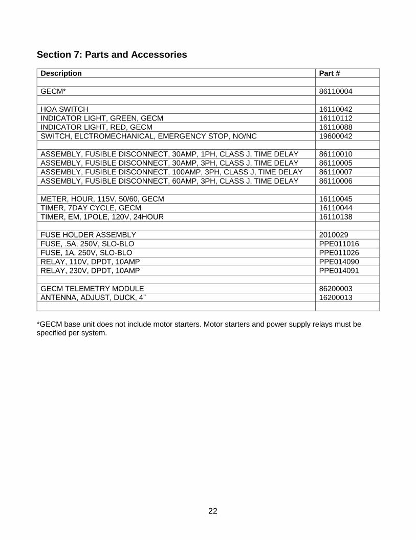
Section 7: Parts and Accessories
Description Part #
GECM* 86110004
HOA SWITCH 16110042
INDICATOR LIGHT, GREEN, GECM 16110112
INDICATOR LIGHT, RED, GECM 16110088
SWITCH, ELCTROMECHANICAL, EMERGENCY STOP, NO/NC 19600042
ASSEMBLY, FUSIBLE DISCONNECT, 30AMP, 1PH, CLASS J, TIME DELAY 86110010
ASSEMBLY, FUSIBLE DISCONNECT, 30AMP, 3PH, CLASS J, TIME DELAY 86110005
ASSEMBLY, FUSIBLE DISCONNECT, 100AMP, 3PH, CLASS J, TIME DELAY 86110007
ASSEMBLY, FUSIBLE DISCONNECT, 60AMP, 3PH, CLASS J, TIME DELAY 86110006
METER, HOUR, 115V, 50/60, GECM 16110045
TIMER, 7DAY CYCLE, GECM 16110044
TIMER, EM, 1POLE, 120V, 24HOUR 16110138
FUSE HOLDER ASSEMBLY 2010029
FUSE, .5A, 250V, SLO-BLO PPE011016
FUSE, 1A, 250V, SLO-BLO PPE011026
RELAY, 110V, DPDT, 10AMP PPE014090
RELAY, 230V, DPDT, 10AMP PPE014091
GECM TELEMETRY MODULE 86200003
ANTENNA, ADJUST, DUCK, 4” 16200013
*GECM base unit does not include motor starters. Motor starters and power supply relays must be specified per system.

23
Appendix A – Customer and Device Information
Customer Name:
Sales Order Number:
Build Date:
GECM Serial Number:
Voltage/Phase:
Device Name: Serial Number: Model Number:

24
Appendix B - Glossary of Acronyms AUX Auxiliary BLWR Blower ECM Electronic Control Module GECM Geotech Environmental Control Module H2O Water (when on 1st line of display on SDFS system) H2O Water pump (2nd line of message on SDFS/PSCAV system)) H2OL Water level low (SDFS intake cartridge or PSCAV water HI/LO float) H2OM Water level middle (SDFS intake cartridge or PSCAV water HI/LO float) H2OH Water level high (SDFS intake cartridge or PSCAV water HI/LO float) HI High HOA Hand-Off-Auto (switch) HP Horse Power IS Intrinsically Safe JB Junction Box LH HI/LO float high (Sump probe, 3 position probe) LL HI/LO float low (Sump probe, 3 position probe) LM HI/LO float middle (Sump probe, 3 position probe) LO Low LOPRO Low Profile Air Stripper ORH Override float (water) high (SDFS/PSCAV probe) ORL Override float (water) low (SDFS/PSCAV probe) ORS Oil Recovery Systems PCB Printed Circuit Board PH Phase (electrical term) PH Product float high (SDFS/PSCAV probe) PL Product float low (SDFS/PSCAV probe) PM Product float middle (SDFS/PSCAV probe) PSCV Probe Scavenger (4” Small Diameter PSCAV) PSCAV Probe Scavenger (4” Small Diameter PSCAV) PSI Pressure per Square Inch PROD Product pump RES Reservoir (SDFS) SDFS Small Diameter Filter Scavenger SN Serial Number SPRG Air Sparge unit SVE Soil Vapor Extractor (Extraction) VAC Voltage Alternating Current VDC Voltage Direct Current VFD Variable Frequency Drive, or Vacuum Fluorescent Display WTDP Water Table Depression Pump XFER Transfer Pump

25
DOCUMENT REVISIONS
EDCF# DESCRIPTION REV/DATE
- Previous Revision 11/7/2011
1544 Added WTDP Display Definitions in Section 3 3/13/2013
1544 Added Field Programmer Instructions in Section 2 10/1/2013
Project # 1518 Updated to include Auxilliary Alarm and Telemetry information, removed test
specifications (moved to device specific), general updates, SB 6/6/2017
26
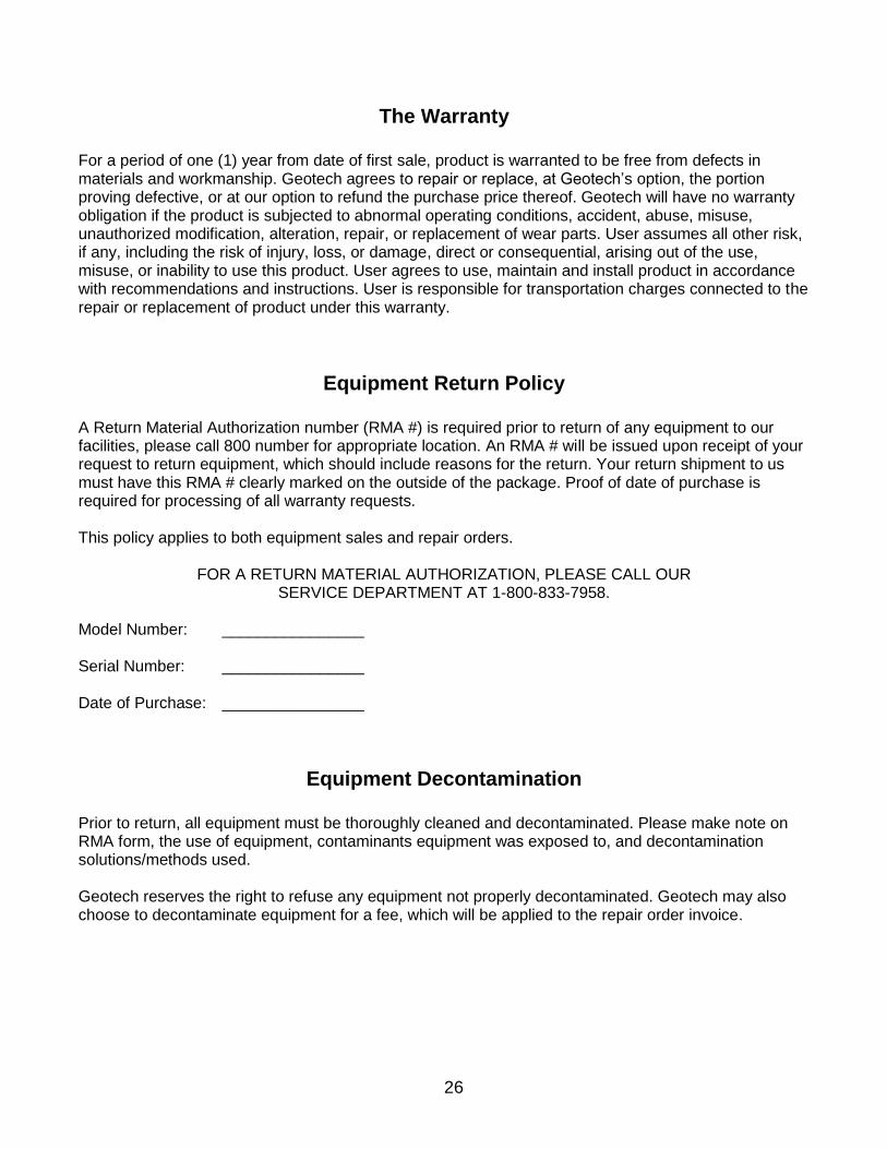
The Warranty
For a period of one (1) year from date of first sale, product is warranted to be free from defects in materials and workmanship. Geotech agrees to repair or replace, at Geotech’s option, the portion proving defective, or at our option to refund the purchase price thereof. Geotech will have no warranty obligation if the product is subjected to abnormal operating conditions, accident, abuse, misuse, unauthorized modification, alteration, repair, or replacement of wear parts. User assumes all other risk, if any, including the risk of injury, loss, or damage, direct or consequential, arising out of the use, misuse, or inability to use this product. User agrees to use, maintain and install product in accordance with recommendations and instructions. User is responsible for transportation charges connected to the repair or replacement of product under this warranty.
Equipment Return Policy
A Return Material Authorization number (RMA #) is required prior to return of any equipment to our facilities, please call 800 number for appropriate location. An RMA # will be issued upon receipt of your request to return equipment, which should include reasons for the return. Your return shipment to us must have this RMA # clearly marked on the outside of the package. Proof of date of purchase is required for processing of all warranty requests. This policy applies to both equipment sales and repair orders.
FOR A RETURN MATERIAL AUTHORIZATION, PLEASE CALL OUR SERVICE DEPARTMENT AT 1-800-833-7958.
Model Number: ________________ Serial Number: ________________ Date of Purchase: ________________
Equipment Decontamination
Prior to return, all equipment must be thoroughly cleaned and decontaminated. Please make note on RMA form, the use of equipment, contaminants equipment was exposed to, and decontamination solutions/methods used. Geotech reserves the right to refuse any equipment not properly decontaminated. Geotech may also choose to decontaminate equipment for a fee, which will be applied to the repair order invoice.

Geotech Environmental Equipment, Inc
2650 East 40th Avenue Denver, Colorado 80205 (303) 320-4764 ● (800) 833-7958 ● FAX (303) 322-7242
email: [email protected] website: www.geotechenv.com