geotech geocontrol pro - rice rentals manuals/geotech/geotech_geocontrol_pro... · unit must be...
TRANSCRIPT

Geotech
Geocontrol PRO
Installation and Operation Manual
Rev 08/20/2012 Part# 11150263

TABLE OF CONTENTS
DOCUMENTATION CONVENTIONS ..........................................................................................................2
NOTICES .....................................................................................................................................................2
CHAPTER 1: SYSTEM DESCRIPTION ......................................................................................................4
CHAPTER 2: SYSTEM INSTALLATION .....................................................................................................5
CHAPTER 3: SYSTEM OPERATION ..........................................................................................................6
CHAPTER 4: SYSTEM MAINTENANCE ....................................................................................................8
CHAPTER 5: SYSTEM TROUBLESHOOTING ..........................................................................................9
CHAPTER 6: SYSTEM SPECIFICATIONS ...............................................................................................11
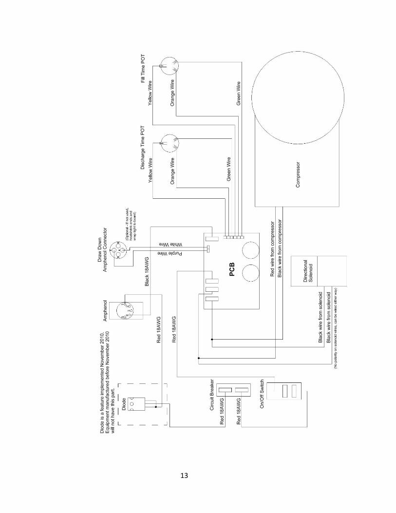
CHAPTER 7: SYSTEM SCHEMATIC........................................................................................................12
CHAPTER 8: REPLACEMENT PARTS LIST ............................................................................................15
THE WARRANTY ......................................................................................................................................17
EQUIPMENT RETURN POLICY ...............................................................................................................17
EQUIPMENT DECONTAMINATION .........................................................................................................17
DECLARATION OF CONFORMITY ..........................................................................................................18
1
DOCUMENTATION CONVENTIONS
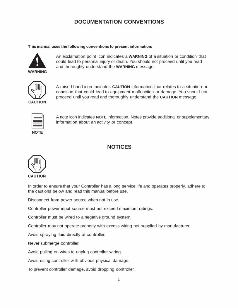
This manual uses the following conventions to present information:
WARNING
An exclamation point icon indicates a WARNING of a situation or condition that
could lead to personal injury or death. You should not proceed until you read
and thoroughly understand the WARNING message.
CAUTION
A raised hand icon indicates CAUTION information that relates to a situation or
condition that could lead to equipment malfunction or damage. You should not
proceed until you read and thoroughly understand the CAUTION message.
A note icon indicates NOTE information. Notes provide additional or supplementary
information about an activity or concept.
NOTE
NOTICES
CAUTION
In order to ensure that your Controller has a long service life and operates properly, adhere to
the cautions below and read this manual before use.
Disconnect from power source when not in use.
Controller power input source must not exceed maximum ratings.
Controller must be wired to a negative ground system.
Controller may not operate properly with excess wiring not supplied by manufacturer.
Avoid spraying fluid directly at controller.
Never submerge controller.
Avoid pulling on wires to unplug controller wiring.
Avoid using controller with obvious physical damage.
To prevent controller damage, avoid dropping controller.

2
NOTE
The Geotech Geocontrol PRO cannot be made dangerous or unsafe as a result of failure due to
EMC interference.
WARNING
Do not operate this equipment if it has visible signs of significant physical damage other than
normal wear and tear.
Notice for consumers in Europe:
This symbol indicates that this product is to be collected separately.
The following apply only to users in European countries:
• This product is designated for separate collection at an appropriate collection point.
Do not dispose of as household waste.
• For more information, contact the seller or the local authorities in charge of waste
management.
3
Chapter 1: System Description
Function and Theory The Geocontrol PRO is a unique controller for operating down well bladder type sampling
pumps. When an external 12 VDC power source is connected to the controller, the internal
air compressor is capable of producing a pressure of 100 PSI (7 bar). This pressure allows the
user to take samples from a depth to 180 feet (55 mm). The controller offers a variable cycle timer for controlling the portable compressor’s on-time
and off-time. While the compressor is on, air is pushed down well to the bladder pump, com-
pressing the internal bladder and evacuating the liquid in the pump. When the compressor
shuts off, the air pressure in the pump exhausts out of the system, allowing liquids to enter
the pump.
4
Chapter 2: System Installation
WARNING
Verify the 12V system to be used is rated and fuse protected for operation at 15 amps continu-
ous operation. Failure to verify system rating could result in damage to equipment. Over-heated
wiring and other materials or components in contact or near by the power delivery system
could pose a potential fire or burn hazard.
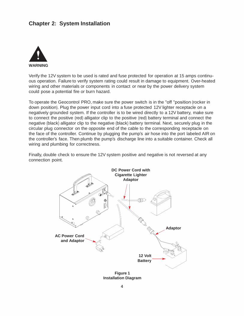
To operate the Geocontrol PRO, make sure the power switch is in the “off “position (rocker in
down position). Plug the power input cord into a fuse protected 12V lighter receptacle on a
negatively grounded system. If the controller is to be wired directly to a 12V battery, make sure
to connect the positive (red) alligator clip to the positive (red) battery terminal and connect the
negative (black) alligator clip to the negative (black) battery terminal. Next, securely plug in the
circular plug connector on the opposite end of the cable to the corresponding receptacle on
the face of the controller. Continue by plugging the pump’s air hose into the port labeled AIR on
the controller’s face. Then plumb the pump’s discharge line into a suitable container. Check all
wiring and plumbing for correctness.
Finally, double check to ensure the 12V system positive and negative is not reversed at any
connection point.
DC Power Cord with
Cigarette Lighter
Adaptor
AC Power Cord
and Adaptor
Adaptor
12 Volt
Battery
Figure 1
Installation Diagram
5
Chapter 3: System Operation
WARNING
Do not operate this equipment if it has visible signs of significant physical damage other than
normal wear and tear.
CAUTION
Operating the equipment in any way other than that described within this document could
potentially damage the equipment.
Disconnect power source when not in use.
Double check 12V system positive and negative are not reversed at any connection point.
Before turning the power switch “on” turn the Geocontrol PRO’s “Fill” and “Discharge” timer
knobs to adjust the cycle times. These knobs are located on the front face of the Geocontrol
PRO below the airline pressure gauge. To the left is Discharge time and to the right is Fill time.
Use the radial number scales around each timer knob to adjust timer values in seconds.
Discharge Time:
The time it takes to squeeze the bladder and push the water out of the pump. Increase this
time with increased depth to water and larger bladder pumps. Decrease this time with lower
depth to water and smaller bladder pumps. Timer can be set from approximately 2 to 60 sec.
Fill Time:
The time allowed for the bladder to refill. Increase this time with increased depth to water and
larger bladder pumps. Decrease this time with lower depth to water and smaller bladder
pumps. Timer can be set from approximately 2 to 60 seconds. Fill rate depends on hydrostatic
pressure (pressure from the water above the pump) and will vary depending on pump place-
ment within the water column. Therefore, the more water above the pump the faster it will fill.
Turn the controller power switch ON. In case of long fluid discharge lines it could take multiple
cycles for water to reach the outlet. If the fluid discharge from the pump falls off before the
discharge cycle is complete, the discharge time is set too high. This could result in a creased
bladder that will reduce per cycle pump volumes. Therefore, if the compressor is still running
and water has stopped coming out of the discharge tube, the discharge time should be
decreased. Pumping efficiency can be maximized by measuring the amount of fluid discharged.
If the volume of fluid after one pump cycle is less than the rated volume of the pump being
used, then the fill rate can be increased.
6
The air line pressure gauge can be utilized to maximize efficiency. As a general rule, the pressure
indicated on the gauge should not exceed an equivalent depth to water pressure. 1 PSI = 2.31
feet (1 bar=1.02 m) of water. Once the bladder in the pump is empty of liquids the pressure will in-
crease sharply. If a quick pressure increase is noticed, reduce the discharge time until the quick
pressure increase is no longer obvious.
For example, if the well you are sampling has a depth to water of 23 feet (7 m) you should not
expect to see a reading on the pressure gauge much over 10 PSI (.7 bar). When the discharge
cycle begins the reading on the pressure gauge will begin to rise. Once depth to water pressure
has been reached the reading will ‘stall’ at that pressure until the bladder is empty or discharged.
Once the bladder is compressed completely the pressure will again start to rise. For maximum
per cycle liquid pumping volume, this is the optimum point at which the discharge timer would
expire and the fill rate timer would begin. Reduced per cycle liquid pumping volume can be
achieved by further decreasing the discharge time, thus evacuating only part of the total blad-
der volume.
CAUTION
For use with negative (-) ground systems only.
Exceeding the recommended duty cycle will cause overheating.
Damage will result if the supply voltage exceeds 14 VDC.
7
Chapter 4: System Maintenance Maintenance Procedures
Disconnect power source when not in use.
Unit must be returned to Geotech Environmental Equipment for any service. In order to ensure a
long service life, keep the Geocontrol PRO clean. Often a soft, damp cloth can be used to remove
dust and dirt from the exterior surfaces of the Geocontrol PRO. In extreme cases, or to remove
aged caked on dirt and dust, a mild soap and water solution can be applied to a soft cloth and
used to clean the exterior surfaces of the Geocontrol PRO. Do not soak or directly spray liquids
on the Geocontrol PRO.
WARNING
Equipment should be repaired by Geotech Environmental Equipment factory trained repair
technicians only. Improper repair of equipment may result in degradation of performance
and/or service life. Disassembly exposes potentially dangerous moving components that could
injure someone who is not properly trained to repair this equipment.
Solenoid Maintenance
The following procedure outlines how to remove, dis-assemble and clean a stuck or clogged
breather vents on the solenoid.
• If you have brass breather vents and would like to replace them with the newer version of
stainless steel breather vents, contact Geotech Environmental Equipment and reference part #
11150333.
• Note: The space that you will be working in will be pretty tight, so you will might need to use
needle nose pliers to disassemble and reassemble the solenoid.
• Tools needed: Phillips head screwdriver
1/4” wrench
7/16” wrench
Needle nose pliers
1. Unplug unit.
2. Remove clear tubing that connects to the compressor and the air pressure gage. Note that you
should not remove this tubing at the connections on the solenoid. See Figure 4-1.

8
Figure 4-1
3. Remove the two screws that connect the solenoid to the casing. You do not have to disconnect
the 3 black wires from the solenoid, they should be long enough to allow you to set the solenoid
down on a flat surface for cleaning. See Figure 4-2.
Figure 4-2
9
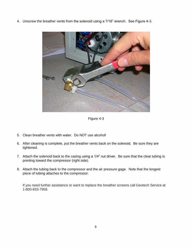
4. Unscrew the breather vents from the solenoid using a 7/16” wrench. See Figure 4-3.
Figure 4-3
5. Clean breather vents with water. Do NOT use alcohol!
6. After cleaning is complete, put the breather vents back on the solenoid. Be sure they are
tightened.
7. Attach the solenoid back to the casing using a 1/4” nut driver. Be sure that the clear tubing is
pointing toward the compressor (right side).
8. Attach the tubing back to the compressor and the air pressure gage. Note that the longest
piece of tubing attaches to the compressor.
If you need further assistance or want to replace the breather screens call Geotech Service at
1-800-833-7958.

10
Chapter 5: System Troubleshooting The Geocontrol PRO has been designed and manufactured to provide a long service life and
trouble free operation in the field. If the compressor, during charge cycles, becomes sluggish,
check supply voltage. If the supply voltage falls below 12 VDC, the compressor’s performance
will be directly affected. A fully charged battery will produce the best results.
Other sources of low pump output may be 12V lighter receptacles or plugs. Make certain these
connections are securely plugged in and clear of any debris. Once securely plugged in, rotating
the connection can often help if there is a dead spot in the connector. Also, check for connec-
tion and cable fatigue, cracks, surface oxidation, rust etc.
If the compressor does not turn on:
• Double check battery polarity is correct. In other words, the positive and negative cables are
connected positive to positive and negative to negative. The Geocontrol PRO is protected
from damage due to reverse polarity connection.
• Turn the power switch to the OFF position and let the unit sit in the OFF state for two
minutes. This will hard reset the electronic timer module.
• If ambient temperatures are in excess of 104°F (~40°C) then disconnect from power and let
sit in a cool location. Do not open the case for any reason. This will not hasten the cooling
process, but will invite debris into internal components that could result in reduced life or
immediate equipment failure.
• If the compressor still does not turn on the electronic timer module may have failed.
Call Geotech Service at 1-800-833-7958 to arrange for the equipment to be sent back to
a factory authorized repair location.
• If 15 Amp circuit breaker is tripped, push to reset. If it trips again, call Geotech Service
at 1-800-833-7958 to arrange the equipment to be sent back to a factory authorized
repair location.
Compressor turns on and fluid is being pumped but no pressure is indicated on the gauge.
• The pressure gauge has failed; however operation of the device may continue even though
the gauge feature is not operational. Call Geotech Service at 1-800-833-7958 to arrange for
the equipment to be sent back to a factory authorized repair location.
Fluid is not being pumped and the compressor turns on, no pressure is indicated on the gauge.
• Remove the air line from the front of the Geocontrol PRO. Block the air outlet on the front
of the Geocontrol PRO while the compressor is running to verify the pressure gauge needle
indicates an increase in pressure. Remove the blockage from the air outlet and observe
whether or not a small burst of compressed air is released. If pressure cannot be built at the
outlet on the front of the Geocontrol PRO, call Geotech Service at 1-800-833-7958 to arrange
for the equipment to be sent back to a factory authorized repair location.
• If pressure can be built at the air outlet on the front of the Geocontrol PRO while the compres-
sor is running:

11
1) Attach the air line only and block the end. Verify the pressure gauge needle indicates an
increase in pressure. Remove the blockage from the end of the air line and observe
whether or not a small burst of compressed air is released. If pressure cannot be built at
the end of the air line, check the air line for cuts, kinks and holes, especially at, and near,
the bladder pump hose barb or compression fitting connections.
• If pressure can be built at the end of the air line while the compressor is running:
1) Attach the air line to the bladder pump. Remove the fluid discharge tube from the blad-
der pump. While the compressor is running, very little air discharge should be felt at the
pump discharge fitting. The pressure gauge on the front of the Geocontrol PRO should in-
dicate a rise in pressure. If this does not occur and a continuous air flow can still be felt
at the pump fluid discharge fitting, then the bladder, or bladder seal, has been compro-
mised and should be repaired or replaced. Information on this procedure can be found in
the product manual specific to the bladder pump being used. Or call Geotech Service at
1-800-833-7958 for further assistance.
2) Reminder: Be careful not to over pressurize and crease the bladder inside the pump as
this will reduce the fluid flow during normal operation.

12
Chapter 6: System Specifications
Power Requirements:
72-84 W
12-14 VDC input at 7.5 Amps
Nominal Operating Current:
6 Amps DC
Over Current Protection:
15 Amps
Timer:
Discharge Time
Fill Time
1.8 sec. min. – 60 sec. max.
1.8 sec. min. – 60 sec. max.
Maximum Operating Depth:
180 ft. (55 m)
Maximum Operating Pressure:
100 PSI (7 bar) (self limited for safety)
Ambient Operational Temperature:
50°F-104°F (10°C-40°C)
Dimensions:
6.70" H x 4.80" x 11.40" W
(17.02cm H x 12.92cm D x 28.96cm W)
Weight:
9 lbs. (4 kg) total
Features
• Variable pump Discharge time control.
• Variable pump Fill time control.
• Interchangeable pump connection configurations.
• Operation with dedicated pump systems and special purpose well caps.
• Approx. 45 to 60 minute operation with 7.5Ah lead acid battery (Battery Module w/o
Charger, Geotech PN: 77250001).
• Reverse polarity protection.
• AC adapter optional for use with world mains connection.
13
14
27
:
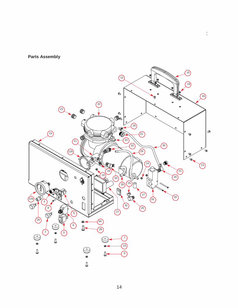
Parts Assembly
10
13
19
1b
32
23
25
1a 21
11 33
20 30
12b 29
14 13
24 22
14
20 20
28 25
17
12a 16 18
4
31 8 20
5
26
34
6
35 2 3
7
15
9
15
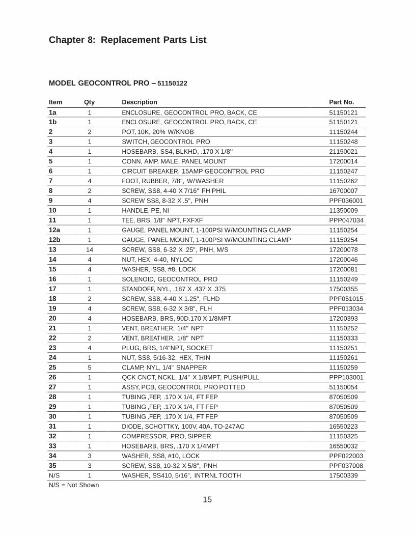
Chapter 8: Replacement Parts List
MODEL GEOCONTROL PRO – 51150122
Item Qty Description Part No.
1a 1 ENCLOSURE, GEOCONTROL PRO, BACK, CE 51150121
1b 1 ENCLOSURE, GEOCONTROL PRO, BACK, CE 51150121
2 2 POT, 10K, 20% W/KNOB 11150244
3 1 SWITCH, GEOCONTROL PRO 11150248
4 1 HOSEBARB, SS4, BLKHD, .170 X 1/8" 21150021
5 1 CONN, AMP, MALE, PANEL MOUNT 17200014
6 1 CIRCUIT BREAKER, 15AMP GEOCONTROL PRO 11150247
7 4 FOOT, RUBBER, 7/8", W/ WASHER 11150262
8 2 SCREW, SS8, 4-40 X 7/16" FH PHIL 16700007
9 4 SCREW SS8, 8-32 X .5", PNH PPF036001
10 1 HANDLE, PE, NI 11350009
11 1 TEE, BRS, 1/8" NPT, FXFXF PPP047034
12a 1 GAUGE, PANEL MOUNT, 1-100PSI W/MOUNTING CLAMP 11150254
12b 1 GAUGE, PANEL MOUNT, 1-100PSI W/MOUNTING CLAMP 11150254
13 14 SCREW, SS8, 6-32 X .25", PNH, M/S 17200078
14 4 NUT, HEX, 4-40, NYLOC 17200046
15 4 WASHER, SS8, #8, LOCK 17200081
16 1 SOLENOID, GEOCONTROL PRO 11150249
17 1 STANDOFF, NYL, .187 X .437 X .375 17500355
18 2 SCREW, SS8, 4-40 X 1.25", FLHD PPF051015
19 4 SCREW, SS8, 6-32 X 3/8", FLH PPF013034
20 4 HOSEBARB, BRS, 90D.170 X 1/8MPT 17200393
21 1 VENT, BREATHER, 1/4" NPT 11150252
22 2 VENT, BREATHER, 1/8" NPT 11150333
23 4 PLUG, BRS, 1/4"NPT, SOCKET 11150251
24 1 NUT, SS8, 5/16-32, HEX, THIN 11150261
25 5 CLAMP, NYL, 1/4" SNAPPER 11150259
26 1 QCK CNCT, NCKL, 1/4" X 1/8MPT, PUSH/PULL PPP103001
27 1 ASSY, PCB, GEOCONTROL PRO POTTED 51150054
28 1 TUBING ,FEP, .170 X 1/4, FT FEP 87050509
29 1 TUBING ,FEP, .170 X 1/4, FT FEP 87050509
30 1 TUBING ,FEP, .170 X 1/4, FT FEP 87050509
31 1 DIODE, SCHOTTKY, 100V, 40A, TO-247AC 16550223
32 1 COMPRESSOR, PRO, SIPPER 11150325
33 1 HOSEBARB, BRS, .170 X 1/4MPT 16550032
34 3 WASHER, SS8, #10, LOCK PPF022003
35 3 SCREW, SS8, 10-32 X 5/8", PNH PPF037008
N/S 1 WASHER, SS410, 5/16", INTRNL TOOTH 17500339
N/S = Not Shown
16
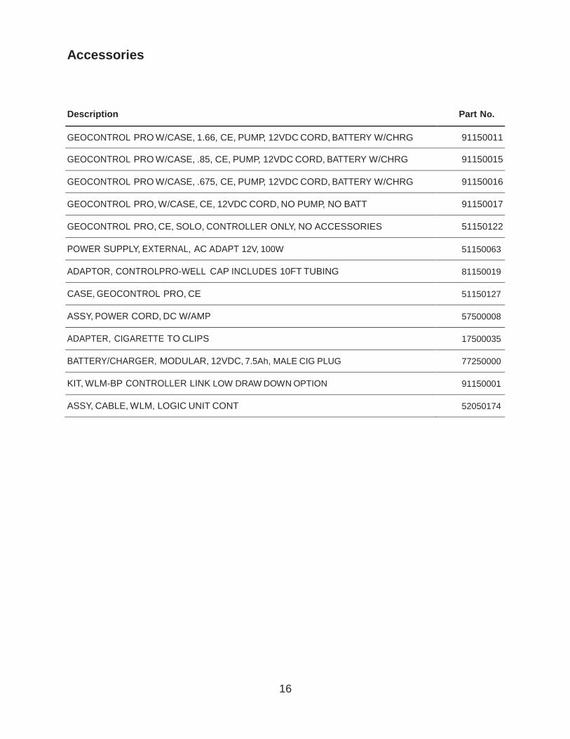
Accessories
Description Part No.
GEOCONTROL PRO W/CASE, 1.66, CE, PUMP, 12VDC CORD, BATTERY W/CHRG
91150011
GEOCONTROL PRO W/CASE, .85, CE, PUMP, 12VDC CORD, BATTERY W/CHRG
91150015
GEOCONTROL PRO W/CASE, .675, CE, PUMP, 12VDC CORD, BATTERY W/CHRG
91150016
GEOCONTROL PRO, W/CASE, CE, 12VDC CORD, NO PUMP, NO BATT
91150017
GEOCONTROL PRO, CE, SOLO, CONTROLLER ONLY, NO ACCESSORIES
51150122
POWER SUPPLY, EXTERNAL, AC ADAPT 12V, 100W
51150063
ADAPTOR, CONTROLPRO-WELL CAP INCLUDES 10FT TUBING
81150019
CASE, GEOCONTROL PRO, CE
51150127
ASSY, POWER CORD, DC W/AMP
57500008
ADAPTER, CIGARETTE TO CLIPS
17500035
BATTERY/CHARGER, MODULAR, 12VDC, 7.5Ah, MALE CIG PLUG
77250000
KIT, WLM-BP CONTROLLER LINK LOW DRAW DOWN OPTION
91150001
ASSY, CABLE, WLM, LOGIC UNIT CONT
52050174
17
THE WARRANTY For a period of one (1) year from date of first sale, product is warranted to be free from defects
in materials and workmanship. Geotech agrees to repair or replace, at Geotech’s option, the
portion proving defective, or at our option to refund the purchase price thereof. Geotech will
have no warranty obligation if the product is subjected to abnormal operating conditions, acci-
dent, abuse, misuse, unauthorized modification, alteration, repair, or replacement of wear parts.
User assumes all other risk, if any, including the risk of injury, loss, or damage, direct or conse-
quential, arising out of the use, misuse, or inability to use this product. User agrees to use,
maintain and install product in accordance with recommendations and instructions. User is
responsible for transportation charges connected to the repair or replacement of product
under this warranty.
Equipment Return Policy
A Return Material Authorization number (RMA #) is required prior to return of any equipment to
our facilities, please call Geotech Service for appropriate location. An RMA # will be issued
upon receipt of your request to return equipment, which should include reasons for the return.
Your return shipment to us must have this RMA # clearly marked on the outside of the package.
Proof of date of purchase is required for processing of all warranty requests.
This policy applies to both equipment sales and repair orders.
FOR A RETURN MATERIAL AUTHORIZATION, PLEASE CALL OUR SERVICE DEPARTMENT AT
1-800-833-7958
Model Number:
Serial Number:
Date of Purchase:
Equipment Decontamination
Prior to return, all equipment must be thoroughly cleaned and decontaminated. Please make
note on RMA form, the use of equipment, contaminants equipment was exposed to, and
decontamination solutions/methods used.
Geotech reserves the right to refuse any equipment not properly decontaminated. Geotech
may also choose to decontaminate equipment for a fee, which will be applied to the repair
order invoice.

18
Declaration of Conformity
Geotech Environmental Equipment Inc.
2650 E 40th Avenue
Denver, CO 80205
Following products are covered:
Geotech product PN
81150018 Geocontrol Pro w/case .675 PBP
81150017 Geocontrol Pro w/case .85 PBP
81150016 Geocontrol Pro w/case 1.66 PBP
81150012 Geocontrol Pro w/case
These products comply with the directive 2004/108/EC (EMC), harmonized standard
EN 61010-1 2001-12-07, emissions class A.
These products comply with harmonized standard EN 61326-1 May 2006.
Signatory:
Joe Leonard
Product Development
Year of manufacture: 2010
EMC conformity established 8/14/2009.
This declaration is issued under the sole responsibility of
Geotech Environmental Equipment Inc.
Model
Serial Number


Geotech Environmental Equipment, Inc. 2650 East 40th Avenue • Denver, Colorado 80205 (303)
320-4764 • (800) 833-7958 • FAX (303) 322-7242
email: [email protected] website: www.geotechenv.com In the EU
Geotech Equipos Ambientales S.L.
Abat Escarré # 12 Mollet del Valles, Barcelona 08100, España
Tlf: 93 5445937
email: [email protected] • website: www.geotechenv.com/spain.html
Printed in the United States of America
Rev. 10/25/2011 Part #11150263