genrad 1413 precision decade capacitor
TRANSCRIPT

♦ PRECISION INSTRUMENTS FOR TEST AND MEASUREMENT ♦
GenRad 1413 Precision
Decade Capacitor
User and Service Manual

ii
Contents
WARRANTY ........................................................................................... iiiWARNING ............................................................................................... vCAUTION................................................................................................ vSection 1
INTRODUCTION .......................................................................... 11.1 Purpose .................................................................................. 11.2 Description ............................................................................. 11.3 Controls and Connectors ....................................................... 11.4 Inspection and Unpacking .................................................... 2
Section 2SPECIFICATIONS ......................................................................... 3
Section 3OPERATION PROCEDURE ....................................................... 4
3.1 Dimensions ............................................................................ 43.2 Mounting ................................................................................ 43.3 Connections ........................................................................... 5
3.3.1 Three-Terminal Capacitor ............................................. 5Section 4
THEORY .......................................................................................... 64.1 Circuit Description .................................................................. 64.2 Frequency Characteristics ..................................................... 6
Section 5SERVICE .......................................................................................... 7
5.1 Customer Service .................................................................. 75.2 Instrument Return .................................................................. 7
Section 6MAINTENANCE ............................................................................ 8
6.1 Minimum Performance Standards ......................................... 86.1.1 General .......................................................................... 86.1.2 Capacitance ................................................................... 86.1.3 Terminal Capacitance .................................................... 86.1.4 Insulation Resistance ..................................................... 9
6.2 Adjustments ......................................................................... 116.3 Knob Removal and Replacement ........................................ 11
Section 7PARTS LISTS AND DIAGRAMS .............................................. 12

iii
FiguresFigure 1-1. Elementary schematic diagram of the Type 1413 Decade
Capacitor. Connections for all 24 capacitors are similar to those for the three capacitors shown. .............................................. 1
Figure 1-2. Front panel on the Capacitor.Six 11-position switches with knobs and dials to set desired value
of capacitance between HIGH and LOW terminals. ............ 2Figure 1.3 Connection on the rear panel of the 1413. .............................. 2Figure 3-1. Dimensions of the bench and relay-rack models. .................. 4Figure 6-1. Top interior view of the Capacitor. ....................................... 10Figure 7-2. Schematic circuit diagram for the 1413 Precision Decade Ca-
pacitor. Switches are shown in zero position. ...................... 12
WARNING
OBSERVE ALL SAFETY RULES WHEN WORKING WITH HIGH VOLTAGES OR LINE VOLTAGES.
Dangerous voltages may be present inside this instrument. Do not open the case Refer servicing to qulified personnel
HIGH VOLTAGES MAY BE PRESENT AT THE TERMINALS OF THIS INSTRUMENT
WHENEVER HAZARDOUS VOLTAGES (> 45 V) ARE USED, TAKE ALL MEASURES TO AVOID ACCIDENTAL CONTACT WITH ANY LIVE COMPONENTS.
USE MAXIMUM INSULATION AND MINIMIZE THE USE OF BARE CONDUCTORS WHEN USING THIS INSTRUMENT.
Use extreme caution when working with bare conductors or bus bars.
WHEN WORKING WITH HIGH VOLTAGES, POST WARNING SIGNS AND KEEP UNREQUIRED PERSONNEL SAFELY AWAY.
CAUTION
DO NOT APPLY ANY VOLTAGES OR CURRENTS TO THE TERMINALS OF THIS INSTRUMENT IN EXCESS OF THE MAXIMUM LIMITS INDICATED ON
THE FRONT PANEL OR THE OPERATING GUIDE LABEL.

1INTRODUCTION
1413 Series
Section 1Introduction
connected together, form the third terminal of the ca-pacitor.
The stability of the 1413 (refer to Specifications) issuch that it should not require readjustment with nor-mal service. However, should it become desirable,the four lower decades contain trimmer capacitorsthat are accessible for this purpose (refer to Section5.4).
1.3 Controls and Connectors
The controls and connectors on the front and rear ofthe 1413 are shown in Figures 1-2 and 1-3.
1.1 Purpose
The Type 1413 Precision Decade Capacitor is both ahigh-quality, wide-range standard and a reliable com-ponent for systems. It can be used as a bench modelfor versatility, or it can be rack-mounted.
This six-decade capacitor features fine adjustmentover a wide range of capacitance, with excellent ac-curacy. Any value in the range of 0 to 1.111 11 µFcan be set, with a resolution of 1 pF.
1.2 Description
The six decades have steps of 1, 10, 100, 1000 pF,and 0.01 and 0.1 �F. Air capacitors are used for thetwo lower decades, with precision silvered-mica ca-pacitors for the others. Air trimmers are used for trim-ming the two lowest silvered-mica decades.
The connections to the inner shield and to the caseare shown in Figure 1-1. Low terminal-to-guard anddetector-input capacitances are obtained by dividingthe shielding into two parts. When the two parts areconnected together, the 1413 becomes a well-shieldedthree-terminal capacitor with extremely low zero ca-pacitance. The connections are made by means ofBNC connectors on the rear of the cabinet. The in-ner contacts provide the connections to the capaci-tors. The outer shells connect to the shields and, when
Figure 1-1. Elementary schematic diagram of theType 1413 Decade Capacitor. Connections for all24 capacitors are similar to those for the threecapacitors shown.
2 INTRODUCTION
1413 Series
1.4 Inspection and Unpacking
Inspection - If the shipping carton appears damaged,contact the carrier immediately and request that theiragent be present when the instrument is unpacked. Ifthe instrument appears to be damaged when unpacked,have the agent witness its condition, take photos ofthe instrument and carton, and retain the carton untilthe matter is resolved. Perform an electrical checkimmediately to determine if any internal damage has
occurred and file any required claims with the car-rier.
Unpacking - The instrument is wrapped in plastic, anddesiccant may be included if the environmental con-ditions and destination warrant. Do not unwrap theinstrument until ready to use or install. For bench use,the bail will raise the front of the instrument if de-sired. Refer to 2.2 for rack-mounting instructions.
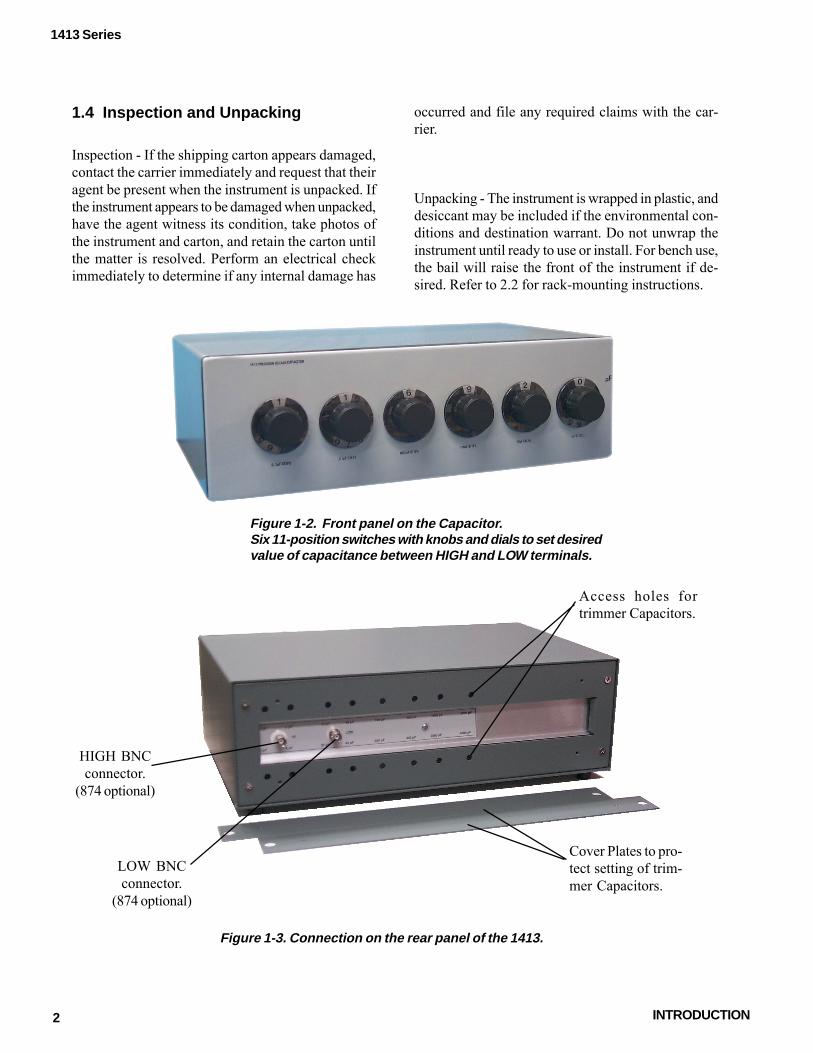
Figure 1-2. Front panel on the Capacitor.Six 11-position switches with knobs and dials to set desiredvalue of capacitance between HIGH and LOW terminals.
Figure 1-3. Connection on the rear panel of the 1413.
Cover Plates to pro-tect setting of trim-mer Capacitors.
Access holes fortrimmer Capacitors.
HIGH BNCconnector.
(874 optional)
LOW BNCconnector.
(874 optional)

3SPECIFICATIONS
1413 Series
Section 2Specifications
Range: 0 to 1.11111 µF. controlled by six in-line-readout dials.
Accuracy: ±(0.05% + 0.5 pF) at 1 kHz.
Stability: ±(0.01% +0.1 pF) per year.Temperature coefficient:
<<20 ppm/oC from 10 to 50°C.
Zero Capacitance: <0.1 pF.
Voltage Rating: 500 V pk max up to 10 kHz.
Interface: Connections, 2 rear-mounted bnc connec-tors, adaptable to most other types.
Available: 0480-9703 Rack Adaptor Set to convertbench models to rack models.
Mechanical: Convertible bench/rack cabinet.Dimensions (w x h x d):17 x 5.59 x 11.96 in. (432 x 142 x 304 mm);rack 19 x 5.22 x 10.9 in. (483 x 133 x 505 mm).Weight: Bench 23 lb (10.5 kg) net, 29 lb (13.5 kg)shipping; rack 24 lb (11 kg) net, 30 lb (14 kg) ship-
CatalogNumber Description
1413-9700 Bench Model1413-9701 Rack Model0480-9703 Rack-Adaptor Set

4 OPERATING PROCEDURE
1413 Series
mounting (P/N 1413-9701), it is shipped with Rack-Adaptor Set P/N 0480-9703, which includes all hard-ware necessary for mounting the instrument in a stan-dard 19-in. rack or cabinet (refer to Table 3-1). (Or-der the Rack-Adaptor set alone if a bench model is tobe converted for rack mounting.)
Section 3Operating Procedure
3.1 Dimensions
The dimensions of both the bench and relay-rackmodels of the 1413 are shown in Figure 3-1,and are also listed in Section 2.
3.2 Mounting
The 1413 may be ordered enclosed in a cabinet forbench use (P/N 1413-9700). If ordered for rack
Figure 3-1. Dimensions of the bench and relay-rack models.

5OPERATING PROCEDURE
1413 Series
CAUTIONRemove the cabinet only when converting the instru-ment from bench to rack mounting or vice versa. Useextreme care. Do not change the position of the leadsor components, as doing so may alter the calibration.
recommends taking accurate spot readings be-fore and after this procedure in order to verify thatthe instrument’s electrical characteristics have notbeen affected. Cover the unit with a plastic sheet whenworking on the cabinet. Clean the inside of the cabi-net thoroughly when installation is complete. Replacethe instrument in the cabinet as soon as possible afterthe work is completed.
To install the instrument in a rack:a. Loosen the four captive 10-32 screws in the rear
of the cabinet until the chassis is free; slide thechassis forward, out of the cabinet.
b. Match drill the cabinet for proper positioning ofthe rack-mount adaptors.
c. Remove the four feet and the bail from the cabi- net if required for clearance.
d. Attach one Rack Adaptor Assembly (G) to eachside of the cabinet using the hardware supplied.
e. Install the instrument in the cabinet and lock it inplace with the four captive screws in the rearpanel that were loosened in step a.
f. Slide the entire assembly into the relay rack andinstall it with the four 9/16-inch screws withcaptive nylon cup washers (E). Use two screwson each side and tighten them by inserting ascrewdriver through the holes in the handles.
To reconvert the instrument for bench use, reversethe above procedure. Seal the mounting holes if theworking environment warrants such action.
3.3 Connections
CAUTIONThe voltage rating of the 1413 is 500 V pk maximumup to 10 kHz, varying approximately inversely withfrequency above 10 kHz. Do not exceed these val-ues.
3.3.1 Three-Terminal Capacitor
When the 1413 is used as a three-terminal capacitor,the outer conductors (shells) of the two bnc connec-tors must be connected together, to provide completeshielding.
If binding-post connections are desired, these can beprovided by standard adaptors plugged into the bncconnectors on the rear of the 1413. Plug the adaptorsinto the 1413 with the shield binding posts adjacent toeach other. These shield posts can then be connectedtogether with a shorting link .
Table 3-1PARTS INCLUDED IN RACK-ADAPTOR SET
P/N 0480-9703Fig. 3-2 No. Ref Used Description Part No. C 2 Rack-Adaptor Assembly (handle) 0480-4903
1 Hardware Set 0480-3080Includes:
D 4 Screws, BH 10-32x 5/16" E 4 Screws, BH 10-32x9/16",
with nylon cup washers
GR

6 THEORY
1413 Series
An elementary schematic is shown in Figure 1-1 andthe complete schematic circuit diagram is given inFigure 7-1.
4.2 Frequency Characteristics
Typical variations of capacitance and dissipation fac-tor with frequency are shown in Section 2.
4.1 Circuit Description
Each decade consists of four capacitors with valuesin the ratio of 1-2-2-5. They are connected in parallelin different combinations to provide ten equal stepsof capacitance. Individual capacitors that are not usedat a particular setting of the switches are completelydisconnected from the circuit and their high side isconnected to the inner or “guard” shield. The innershield and the wiring are arranged to keep the ca-pacitance at the zero setting to a very low value (<0.1 pF) and to keep the capacitance from HIGH tocase and from HIGH and LOW to the inner shield toa minimum.
Section 4Theory

8 MAINTENANCE
1413 Series
6.1.2 Capacitance
The equipment required to check the capacitancevalues of the 1413 is listed in Table 6-1.
Connect the UNKNOWN H and L terminals on the1620 Capacitance Measuring Assembly to the HIGHand LOW terminals, respectively, on the 1413. Makethe measurements at 1 kHz with the 3-terminal con-nection. Use appropriate patch cords up to 0.1 µFand twist them together for measurements above 0.01µF to reduce the error due to inductance of the cables.
At 0.1 µF and higher, low-resistance connections arenecessary to reduce the dissipation-factor errorscaused by lead resistance. Install bnc-to-binding-postadaptors on the 1413. Place the instruments so thatthe binding posts on the adaptors are close to the bridgebinding posts. Make the connections, with #12 AWGcopper wire, from the bridge H and L terminals to the1413 HIGH and LOW terminals. Connect a short cliplead from bridge GND to the shells of both bnc con-nectors on the 1413.
Maximum dissipation-factor readings are given in theSpecifications.
6.1.3 Terminal Capacitance
Use the 1620 Capacitance Measuring Assembly tomake the various terminal-capacitance measurements.The connections are given in Table 6-2.
Section 6Maintenance
--Store the instrument for short periods in a benignand dust-free environment (23 ± 10° C and <60%relative humidity); a laboratory environment is best.For long-term storage, seal the instrument in plastic--with desiccant if possible--and store at temperaturesbetween 10° C and 50° C and humidity <80%; Cali-brate before use. Since the 1413 is a precision instru-ment, recommends that any storage be in a labo-ratory environment.--Clean the external surfaces of the instrument witha soft, dry cloth that may be moistened with a mild,general-purpose cleaner; compressed air may alsobe used. Keep the 1413 connectors and any matingconnectors clean. Do not open the cabinet, and keepthe rear cover plates in place, in order to keep theinside of the instrument dust-free.--Replace the rear cover plates immediately after anyadjustments are completed.
6.1 Minimum Performance Standards
6.1.1 General
The following tests can be used for incoming inspec-tion, periodic checks, or recalibration of the 1413. Therequired equipment is listed in Table 6-1.
GR
9MAINTENANCE
1413 Series
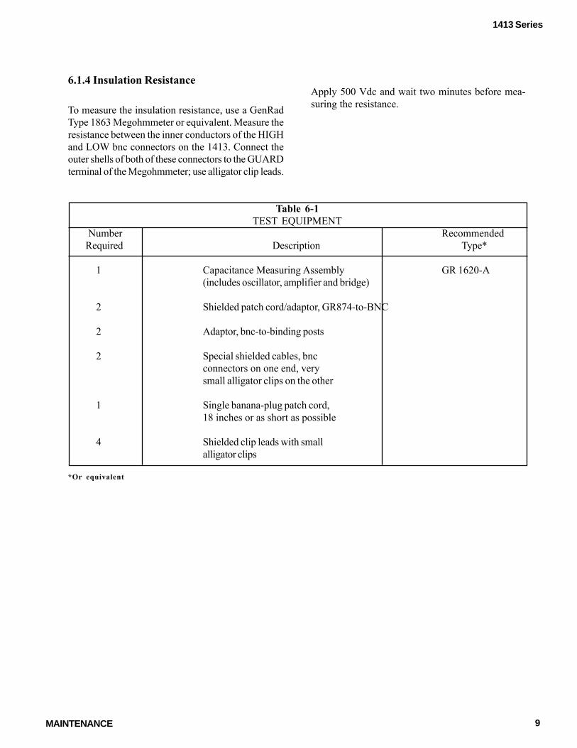
Table 6-1TEST EQUIPMENT
Number RecommendedRequired Description Type*
1 Capacitance Measuring Assembly GR 1620-A(includes oscillator, amplifier and bridge)
2 Shielded patch cord/adaptor, GR874-to-BNC
2 Adaptor, bnc-to-binding posts
2 Special shielded cables, bncconnectors on one end, verysmall alligator clips on the other
1 Single banana-plug patch cord,18 inches or as short as possible
4 Shielded clip leads with smallalligator clips
*Or equivalent
Apply 500 Vdc and wait two minutes before mea-suring the resistance.
6.1.4 Insulation Resistance
To measure the insulation resistance, use a GenRadType 1863 Megohmmeter or equivalent. Measure theresistance between the inner conductors of the HIGHand LOW bnc connectors on the 1413. Connect theouter shells of both of these connectors to the GUARDterminal of the Megohmmeter; use alligator clip leads.

10 MAINTENANCE
1413 Series
Table 6-2Connections for Terminal-Capacitance Measurements
Measurement Connection Lead TypeHIGH to Case Bridge L to 1413 HIGH Patch cord
Bridge H to outer shell of 1413 LOW Shielded clip leadBridge GND to inner conductor of Single banana plug1413 LOW patch cord
HIGH to Guard Bridge H to shell, and L to inner conductor Shielded clip leadsof 1413 HIGHBridge GND to shell and inner Patch cord withconductor of 1413 LOW alligator clips
LOW to Guard Bridge L to 1413 LOW Patch cordBridge H to shell of 1413 HIGH Shielded clip leadBridge GND to inner conductor of Single banana plug1413 HIGH patch cord
Figure 6-1. Top interior view of the Capacitor.

11MAINTENANCE
1413 Series
6.2 Adjustments
Most of the capacitance in the four highest decadesof the 1413 Decade Capacitor is provided by high-quality, precision, sealed, mica capacitors. The ca-pacitance in the two lowest decades (1 pF/step and10 pF/step) is provided by small adjustable air ca-pacitors (see Figure 6-1). Similar capacitors are pro-vided for trimming the next two decades (100 pF/step and 1000 pF/step).
When they are readjusted, a precision three-termi-nal bridge such as the 1620 Capacitance MeasuringAssembly should be used. Set the bridge for three-terminal measurements and connect the capacitorto it with BNC-to-874 patch cords.
Remove the two cover plates over the adjustmentholes (Figure 6-2) on the rear of the case. Do notremove the instrument from its case. Adjust the fourtrimmers in the decade (e.g.. those for the 10 pF/step decade, labelled 10, 20, 40, 50) in order, startingwith the smallest. These numbers refer to the corre-sponding pF dial settings for that decade. Make theadjustments with a non-metallic screwdriver throughthe hole marked with the corresponding pF value.
Set the switch for that decade to the pF value beingadjusted, with all other switches set to zero. For ex-ample, to adjust the 10 pF/step decade, set that dial at10. and adjust the trimmer marked 10 to give 10 pFfrom the HIGH to LOW terminals. Change the dialsetting to 2 and adjust the trimmer marked 20 for 20pF. Proceed similarly with 40 pF and 50 pF.
In the 1-pF/step decade, the capacitors are set to 1.01,2.01, 4.01, and 5.01 pF, respectively. All other de-cades are set to the exact nominal value. When allvalues have been set. it is usually desirable to repeatthe adjustment for a slight “touch-up.”
6.3 Knob Removal and Replacement
If it should become necessary to remove a knob fromthe front panel to change one that has been damaged,proceed as follows:
a. Note the setting of the dial on the shaft, so that itcan be replaced property; then loosen the colletnut in the hub of the dial and slide the dial off ofthe shaft.
b. To replace the knob, reverse the above proce-dure.

12 PARTS LISTS AND DIAGRAMS
1413 Series
Rot
ary
switc
h se
ctio
ns ar
e sho
wn
as v
iew
ed fr
omth
e pa
nel e
nd o
f th
e sh
aft T
he f
irst d
igit
of th
eco
ntac
t num
ber
refe
rs to
the
sect
ion
The
sec
-tio
n ne
ares
t the
pan
el is
1, t
he n
ext s
ectio
n ba
ckis
2, e
tc T
he n
ext t
wo
digi
ts re
fer t
o th
e co
ntac
tC
onta
ct 0
1 is
the
first
pos
ition
clo
ckw
ise
from
ast
rut s
crew
(us
ually
the
scre
w a
bove
the
loca
t-in
g ke
y), a
nd th
e ot
her
cont
acts
are
num
bere
dse
quen
tially
(02,
03,
04,
etc
), pr
ocee
ding
clo
ck-
wis
e aro
und
the s
ectio
n A
suff
ix F
or R
indi
cate
sth
at t
he c
onta
ct i
s on
the
fro
nt o
r re
ar o
f th
ese
ctio
n, r
espe
ctiv
ely
Figu
re 7
-2 S
chem
atic
circ
uit d
iagr
am fo
r the
141
3P
reci
sion
Dec
ade
Cap
acito
r S
witc
hes
are
sho
wn
in z
ero
po
sitio
n
Section 7PARTS LISTS AND DIAGRAMS

13PARTS LISTS AND DIAGRAMS
1413 Series
ELECTRICAL PARTS LIST
Ref Des Description Part No.
CAPACITORS
Cl Air Dielectric, 1.4-5.0 pF 4380-3500C2 Air Dielectric, 1.4-5.0 pF 4380-3500C3 Air Dielectric, 1.4-5.0 pF 4380-3500C4 Air Dielectric, 1.7-8.7 pF 4380-3600C5 Quartz, Var., 0.6-1.8 pF, 4910-1180C11 Air Dielectric, 2.7-19.6 pF 4380-3700C12 Air Dielectric, 2.7-19.6 pF 4380-3700C13 Air Dielectric, 2.7-19.6 pF 4380-3700C14 Air Dielectric, 2.7-19.6 pF 4380-3700C15 Ceramic, 33 pF ±5%, NPO, 500V 4410-0335C21 96.3 pF ±1 pF 0505-4030C22 196.0 pF ±1 pF 0505-4031C23 196.0 pF ±1 pF 0505-4031C24 496.0 pF ±1.3 pF 0505-4032C25 Air Dielectric, 1.7-8.7 pF 4380-3600C26 Air Dielectric, 1.7-8.7 pF 4380-3600C27 Air Dielectric, 1.7-8.7 pF 4380-3600C28 Air Dielectric, 1.7-8.7 pF 4380-3600C31 986.1 pF ±2.1 pF 0505-4033C32 1989 pF ±5 pF 0505-4034C33 1989 pF ±5 pF 0505-4034C34 4989 pF ±5 pF 0505-4035C35 Air Dielectric, 2.7-19.6 pF 4380-3700C36 Air Dielectric, 2.7-19.6 pF 4380-3700C37 Air Dielectric, 2.7-19.6 pF 4380-3700C38 Air Dielectric, 2.7-19.6 pF 4380-3700C41 10,000 pF ±2.5 pF 0505-4036C42 20,000 pF ±5 pF 0505-4037C43 20,000 pF ±5 pF 0505-4037C44 .05 µF ±12.5 pF 0505-4038C51 0.1 µF ±12.5 pF 0505-4039C52 0.2 µF ±50 pF 0505-4040C53 0.2 µF ±50 pF 0505-4040C54 0.5 µF ±125 pF 0505-4041

1413 Series
MECHANICAL PARTS LIST
Front View (See Fig 1-2)
IET Qty Ref Description Pait No.
1 1 Cabinet asm., includes: 4181-2901 1 Bail* 1 Gasket (mat'l.) 0051-0006 1 Foot, left front* 1 Foot, iight front* 2 Foot, l & r, rear*
*Pait of foot/bail kit 6 2 Knob/Dial assembly 350020
6 3 Cap, knob 350019
Rear View (See Fig 1-3)
IET Qty Ref Description Pait No.
1 1 Connector, bnc, isolated (Std.) 31-10/800-2540-03 (Other types optional)
1 2 Connector, bnc 31-221/UG-1094 (Other types optional)
2 3 Cover Plate 1413-8190
14 PARTS LISTS AND DIAGRAMS