genrad · futuredata advanced microprocessor development system reference manual genrad...
TRANSCRIPT

Futuredata
Advanced Microprocessor
Development System
Reference Manual
GenRad future@@JC~@)
5
MICROCOMPUTER SYSTEMS

Futuredata
Advanced Microprocessor
Development. System
Reference Manual 5

Futuredata Advanced Microprocessor Development System
Reference Manual
copyright 1980
Genrad Futuredata Computer Corporation
All rights reserved.
Preliminary-edition
Genrad
5730 Buckingham Park Way Culver City CA 90230
TABLE OF CONTENTS
1 How to Use this Manual
2 Introduction to Microprocessor Development
3 Beginning Operation
4 Conventions
5 Command Files
6 File Manager
7 Editor
8 Assembler
9 Assembler Macros & Conditional Statements
10 Program Segment Linker
11 Debugger
12 Emulator
13 EPROM Programming


Section 1
How to Use This Manual
This manual is designed to allow easy access to information needed by
the user of the Futuredata Advanced Microprocesser Development System.
Sections Sections are placed in the order of use. The beginning of
each section may be found by fanning the manual pages slightly and matching
the appropriate black block on the edge of the Table of Contents page with
that of the section. Sections of more than three pages are indexed.
Pages Each page has one or two lines across the top. If the page
holds information about a command or other input to the AMDS system, there
is one line. If the page holds purely explanatory information, there are
two lines.
Conventions An explanation of the conventions used to describe
commands is given in Section 4.
QUICK INTRODUCTION TO AMDS
For a quick introduction to AMDS features and capabilities, read
only the page headings, the information shown under the subheading PURPOSE
if that subheading is given, and look at the photographs of the keyboard
and the various displays.
PRELIMINARY EDITION
This is a preliminary edition of this manual. The next edition will
be automatically mailed to each AMDS user.
Futuredata AMDS Reference Manual 12/07/78 1-1

Section 2
Introduction to Microprocessor Development
SOFTWARE DEVELOPMENT
The Futuredata Advanced Microprocessor Development System provides
all of the software tools necessary for the rapid development of large
microcomputer programs. Four major functions of the AMDS are used for soft
ware development. These are the Editor, Assembler, Linker, Debugger, and
File Manager.
Software development typically proceeds in the following manner.
First a program in assembly language (or Basic) is typed into the Editor.
The Editor provides a large number of features for easy entry and editing
of text. The finished program is then stored on diskette.
Then the Assembler translates the assembly language program on the
diskette to binary microprocessor instructions. The Assembler is capable
of detecting a number of syntax errors. If there are errors, the program
is edited using the Editor and assembled again. The executable binary
program is stored on disk.
Often the program is written in modules which may be located any
place in memory, and which must be linked together. Relocation and linking
is performed by the Linker. The linked program is stored on a diskette
file.
The program is then executed by the Debugger which prov~des powerful
features for testing. The Debugger displays the contents of memory and the
microprocessor registers. Changes can be made where necessary.
Normally there are execution errors in a program when it is first
written. After the errors are found using the Debugger, changes are made
in the assembly language program using the Editor. The program is assem
bled, linked and tested again. THis process is repeated if necessary until
the program is perfect.
Futuredata AMOS Reference Manual 12/07/78 2-1

Hardware Development Microproces,sor Development
HARDWARE DEVELOPMENT
A hardware prototype is developed using the Emulator, which is pro
vided with a plug which fits directly into a microprocessor socket.
To the prototype, the Emulator appears almost ,exactly as though a
microprocessor were plugged into the socket. However, the keyboard, dis
play, and all of the other features of the AMOS are available to the user
during emulation. This makes testing of the prototype extremely efficient.
The prototype clock, interrupts, control lines, direct memory access,
I/O, and memory may be tested separately.
Futuredata AMOS Reference Manual 12/07/78 2-2

TURNING ON POWER
Section 3
Beginning Operation
To begin operation:
1) Plug diskette drive cable into connector on AMOS back panel.
2) Plug in AMOS power line cord.
3) Turn on switch on back panel.
4) Turn on diskette drive unit.
5) Insert system diskette in drive O. For proper method of insertion see
USING DISKETTES on page 3-3.
6) Wait 5 seconds for drive speed to stabilize.
7) Type J{system-character} to begin operation of one of the Futuredata
system programs. system-character is one of the following:
M File Manager E Editor A Assembler L Linker D Debugger U Utility B Basic Interpreter C Basic Compiler
TURNING OFF POWER
To turn off power:
1) Remove all diskettes. If a diskette is in the drive when power is
turned off, it is possible that the magnetic information stored on
the diskette will be changed.
2) Turn off diskette drive unit.
3) Turn off switch on AMOS back panel.
Futuredata AMOS Reference Manual 12/07/78 3-1

qsinq Diskettes Beginning Operation
HANDLING DISKETTES
A diskette is a flexible disk coated with magnetic material and en
closed in a plastic jacket. A paper envelope is supplied for storage.
Observing the following rules will insure diskette reliability:
1) Never touch the magnetic recording surfaces of the diskette. These
surfaces can be seen through the holes punched in the jacket.
2) When a diskette is not loaded in a diskette drive, it should at all
times be kept in the envelope provided.
3) Never bend a diskette.
4) Never subject a diskette to magnets or magnetic influence. Diskettes
should not be stored near power transformers or motors.
5) Diskettes must be used and stored at a temperature within 50oF. This is
equivalent to 100e to 520 C.
6) Always insert a diskette into the diskette drive carefully.
7) Do not write on the plastic jacket with a lead pencil or ball-point
pen. Use a felt tip pen.
8) Heat and contamination from a carelessly dropped ash can damage a
diskette.
9) Do not expose a diskette to sunlight.
10) Do not attempt to clean the magnetic surface. Abrasions may cause loss
of stored data.
Futuredata AMOS Reference Manual 12/07/78 3-2

Using Diskettes Beginning" Operation
INSERTION INTO DRIVE
The proper position of insertion is shown in the drawing below. To
insert a diskette, depress the drive door latch. Insert the diskette with
the label to the right until a click is heard. Close the drive door.
Once the click is heard on insertion, it is not possible to remove
the diskette until the door is closed and opened again.
PHYSICAL WRITE PROTECTION
A diskette drive will not write on a diskette which has an open write
protection hole or notch. To write magnetic information on a diskette it is
necessary to cover the hole or notch with a tab or label. Tabs or labels are
supplied with the diskette. The magnetic information on a diskette may be
read regardless of write protection. System write protection is also avail
able, see page 6-11.
UNPROTeCTED
Write ProtC TaO
Futuredata AMOS Reference Manual 12/07/78
O V= o© c QCl
o WRITe "'OTecTeo
3-3

LV I ~
Futuredata AMDS keyboard The special keys on the
left are used in text editing. The arrow keys on the right scroll or
space through text (Editor) or memory (Debugger).
the far right are hardware control function keys.
The keys on
It is important to note that the bracket and brace keys to the right
of the Pare never used for entering commands. They are only used when
they are part of text. Brackets and braces in this manual show only the
syntax of commands or required input.

COMMANDS
Section 4
Conventions
All commands and command parameters are printed in Large type.
In Sections 8, 9, and 10, Assembler and Linker input is also shown in
large type.
Command Letters Command letters, which must be typed exactly as
shown, are printed in upper case.
Command Parameters Parameters, which require a choice by the user,
are shown in lower case. If a parameter is optional, it is shown in
brackets: [parameter] If a parameter is required, it is shown in braces:
{required-parameter} Do nvt type the brackets or D£a~es. They only show
syntax and are not part of any command or required input.
Dots in Syntax ..• A series of dots in a command syntax shows that
the parameter previous to the dots may be repeated indefinitely. Vertical
dots have the same meaning.
Blank Spaces No blanks are allowed within system commands, and none
are shoWn. Blanks shown for Assembler and Linker input are required.
Special Keys are Shown with Rectangles A rectangle drawn around a
letter, series of letters, or a word indicates that a special key must be
depressed on the keyboard. The letters shown inside the rectangle are the
same as the letters printed on the key top. Here is an example:
IRETURNI (depress the return key)
Command Entry After each keyboard input the return key must be
depressed to indicate to the system that what was typed is ready to be
entered.
Futuredata AMDS Reference Manual 12/07/78 4-1

File Name Conventions Conventions
FILE NAME CONVENTIONS·
Drive Number Prefix In any case where a file name is required as a
command parameter or an input, d:, where d is the diskette drive number,
must be prefixed to the file name unless the diskette is loaded in drive o. If the prefix is not given, drive 0 is assumed.
Create File Prefix In any case where the file name of an output file
is required as a command parameter or an input, N: (new) may be prefixed to
the file name to create the file before writing to it. The create command
described on page 6-5 may also be used to create a file, but this command
can only be used during File Manager operation, whereas N: may always be
used.
Use of Both Prefixes When both prefixes are used, the sequence
is:
[N:] [d:]file-name
Futuredata AMOS Reference Manual 12/07/78 4-2

INTRODUCTION
Section 5
Command Files
The AMOS allows the user to save frequently used sequences of
commands on a diskette file and later to use this file for command input.
Provision is made for accepting input from the keyboard, prompting for
input, and for passing parameters to commands when initiating command
file operation.
IMPORTANT NOTE
The Assembler and Linker wait for I RETURN I before accepting input
again after operation. A command file must contain a blank line at this
point to ensure that these system programs terminate properly.
Futuredata AMOS Reference Manual 12/07/78 5-1

writing a Command File
Return to Keyboard for Input Command Files
RETURN FOR ONE LINE
[prompt]"L
prompt will be displayed when Command File processing
reaches this line on the diskette file.
Typing I RETURN I causes the AMDS to continue reading commands from the file.
ADDENDUM
prompt must be part of a command. No messages or characters
which are not part of a command are allowed in a
command file. Characters entered at the keyboard must,
when substituted into the line in which the carat L
occurred, become part of a legal command. The command
may continue after the carat L, and other carat L
instructions may be placed in the same line.
RETURN UNTIL A IS INPUT
[prompt]"K
prompt will be displayed.
No characters are allowed after the K.
PURPOSE
This command allows input from the keyboard until " is typed. The
AMOS then continues reading commands from the command file.
ADDENDUM
prompt must be part of a conmand. It may be absent. No char-
acters which are not part of a command are allowed
in a command file.
Futuredata AMOS Reference Manual 12/07/78 5-2

Writing a Command File
Accepting Parameters Command Files
COMMAND
A{n}
n may be any integer from 1 to 9.
PURPOSE
This sequence within a command in a command file will be replaced by
the nth parameter entered at initiation of command file processing.
EXPLANATION
Parameters will replace this sequence by direct substitution. The
command in which the sequence occurs will be expanded or contracted to fit
the parameter.
Futuredata Reference Manual 12/07/78 5-3
Initiating Reading of Command File
Aborting Operation
INITIATING READING
JA{file-name}[,parameter].
Command Files
file-name is the name of the file on which commands have been stored.
parameter is a string of characters which will be directly substituted
into commands on the file.
PURPOSE
This command causes the AMDS to accept further command input from
the file file-name.
EXPLANATION
Reading of this file for command input is terminated when the end-of
the file is reached, or if command file processing is aborted. Up to 9
parameters may be entered.
ABORTING OPERATION
SHIFT: r BREAK I
Command file processing may be aborted by holding the shift key down while
depressing the break key.
Futuredata AMOS Reference Manual 12/07/79

Messages Command Files
NOT A COMMAND FILE
The file specified in a JA file-name command does not have the "C"
attribute.
FIRST CHARACTER OF FILE NOT "J"
The first line of a command file must start with a J command.
Futuredata AMDS Reference Manual 12/07/78 5-5


INTRODUCTION
Section 6
File Manager
The File Manager is a computer program which allows the user to
create, delete, and copy diskette files.
A file is any collection of information such as a program, data, or
binary computer instructions. Each collection of information is
referenced by a file name. A file is first created by executing a command
which writes the file name into the diskette file directory and allocates
to this file at least one track of the 76 available on the diskette. As
information is written to the file, the system automatically allocates
additional tracks as needed. One track at a time is added, unless a
greater number is specified when the file is created.
BEGINNING FILE MANAGER OPERATION
Enter JMIRETURNI to begin operation.
Futuredata AMOS Reference Manual 12/07/78 6-1
Initialize Diskette (I) File Manager
COMMAND
I [drive-number]
drive-number may be 0 or 1.
drive-number may be omitted; the system will specify drive 1.
PURPOSE
Initialization A diskette must be initialized before it can be used
for the first time.
Erasure Initialization erases any information previously stored on
a diskette.
EXPLANATION
As supplied by the manufacturer, diskettes have no magnetic infor
mation written on them. Initialization causes the boundaries of the tracks
which later will hold file information to be defined and formats a file
directory. Before initialization begins, the File Manager displays the
message: INITIALIZE DISKETTE ON UNIT n? Typing Y (yes) starts
initialization. Pressing the jRETURNI key bypasses initialization.
Futuredata AMOS Reference Manual 12/07/78 6-2

Display Diskette Directory (D)
COMMAND
D[drive-number][P]
drive-number may be the integer 0 or 1.
If drive-number is not specified, the value assumed is o. If P is appended, the directory will be printed.
PURPOSE
File Manager
This command displays the file directory information which is on
the diskette loaded in the specified diskette drive. Included in the
directory display are: 1) the drive number in which the diskette is loaded,
2) file names, 3) file attributes, 4) the number of tracks allocated to each
file, 5) the number of tracks on the diskette which have not yet been
allocated.
Futuredata AMDS Reference Manual 12/07/78 6-3

File Name Conventions
Command Conventions File Manager
NAME CONVENTIONS
Each collection of information stored on diskette is called a file
and is referenced by a file name. The File Manager will accept only names
which follow these conventions:
EXAMPLES
1) File names must be one to ten characters in length.
2) The first character must be a letter or a number. After the
first, any other ASCII character which results in a displayed
symbol may be used, such as slash, period, or hypehn.
3) No blanks, commas, or colons are allowed within the name.
These are legal file names:
A
COUNTERS23
COUNT.R
2
Q-B//3
DATA
COMMAND CONVENTIONS
[N:] [drive-number:] {file-name}
N: specifies that the file is to be created.
drive-number: specifies the drive number in which the diskette is loaded.
It may be 0 or 1. If this parameter is not included, 0 is assumed.
EXPLANATION
N: and/or drive-number: may be prefixed to a file-name in any
command in which a file name is one of the parameters. The usage of N: must be appropriate; the file name it prefices must be one that will be
written.
Futuredata AMOS Reference Manual 12/07/78 6-4

Create a File (C or N:) File Manager
CREATE COMMAND
C{file-name}[,tracks[,extension-size]]
tracks is an integer which specifies the initial number of tracks to be
allocated to the newly created file. If omitted, the value used
is 1.
extension-size is an integer which specifies the number of tracks which will
be added to the total allocation of t~acks each time information
written to the file overflows the former allocation. If omitted,
the val~e used is 1.
PREFIX CREATE COMMAND
N: prefixed to any new file name specifies that the system will create the
file before writing to it. See Command Conventions on the previous
page.
Futuredata AMDS Reference Manual 12/07/78 6-5

Scratch a File (S)
Free Unused Space in File (F) File -Manager
SCRATCH FILE COMMAND
S{file-name}
The system will request verification: SCRATCH THIS FILE? Type Y (yes).
Pressing the IRETURij key causes the command to be ignored.
PURPOSE
This command deletes the file name from the directory and releases
the diskette tracks which had been allocated to that file.
The scratch command requires writing to the directory. If the file
has the P attribute (permanent) or if the d{skette is physically write
protected, deletion cannot take place. (See Specify File Attributes
Command in this section for information on the P attribute. See Section 3
for further information on physical write protection.)
FREE UNUSED SPACE IN FILE
F{file-name}
PURPOSE
This command releases unused diskette tracks from a file.
EXPLANATION
If new file information is written over the information on an
existing file, and the new file information does not require as much space
as the overwritten file, the unneeded diskette tracks may be returned to
system availability.
Futuredata AMOS Reference Manual 12/07/78 6-6

Rename File CR)
Exchange File Names (E) File Manager
RENAME FILE COMMAND
R{current-file-name},{new-file-name}
PURPOSE
This command renames a file, leaving all other information
unchanged.
EXCHANGE FILE NAMES COMMAND
E{file-name-one},{file-name-two}
PURPOSE
This command exchanges the names of two files, leaving all other
information unchanged.
Futuredata AMDS Reference Manual 12/07/78 6-7

Copy File File Manager
COMMAND
M{from-file-name},{to-file-name}
M{[d:]from-file-name},{[N:](d: to-file-name} (creates new file)
d is the drive number. It may be 0 or 1.
PURPOSE
Copies (moves) all information stored under from-file-name to the
file to-file-name. to-file-name may be prefixed by N: to indicate that it
is a new file which must be created. In this case, the new file will be
given the same attributes as the "from-file."
d: may be prefixed to any file name to indicate the diskette· drive
number.
EXAMPLE
MFILE-A,N:l:FILE-B
This example creates the file FILE-B and copies the information on
FILE-A to FILE-B. FILE-B is on diskette drive 1.
MFILE-A,N:FILE-B
FILE-B is on diskette drive O.
Futuredata AMOS R~f~r~n("A M;:lnll..-:11 1?/n7/7A

Copy Diskette (X) File Manager
COMMAND
X{from-dr;ve-number},{to-dr;ve-number}[,type]
drive-number may be 0 or 1.
type may be anyone of the following characters:
A copy all files
S copy only files with a Z attribute (system files)
If type is omitted, only files without a Z attribute will be copied.
PURPOSE
This command allows easy bulk copying. It is recommended that at
least one copy be made of an important diskette to insure against loss in
case the original is damaged or lost.
EXPLANATION
The name of each file is displayed as it is being copied. If a
file to be copied already exists on the "to-drive" and has the sa~e name
as a file on the "from-drive," the name of the file and the message WRITE
INTO EXISTING FILE? will be displayed. Typing Y (yes) authorizes writing
over the existing file. Pressing the RETURN key will bypass the copying
of that one file.
Futuredata AMOS Reference Manual 12/07/78 6-9

Specify File Attributes (A) File-Manager
COMMAND
A{file-name}[,attribute[attribute) ... ]
attribute may be any combination of the following characters:
PURPOSE
Data Type Attributes
S source file (text)
C command file (text)
R relocatable object file (binary)
o absolute object file (binary)
Z system file
File Protection Attributes
P permanent file (cannot be deleted)
W write-protected file (cannot be overwritten)
B blind file (not listed in the file directory)
File attributes help prevent the misuse or accidental destruction of
files. Except for a blind file, file attributes are listed in the file
directory display; they are a useful bookkeeping aid.
EXPLANATION
Data Type Attributes Data Type Attributes specify the kind of
information contained in the file. These are helpful in preventing file
misuse. For example, the Assembler will not attempt to assemble a file
with attribute R (relocatable object file). Instead, the system will
display the message:~NOT A SOURCE FILE.
Futuredata AMDS Reference Manual 12/07/78 6-10
specify File Attributes (A) File Manager
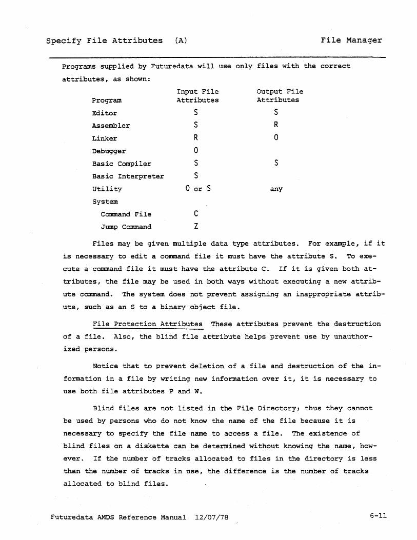
Programs supplied by Futuredata will use only files with the correct
attributes, as shown:
Program
Editor
Assembler
Linker
Debugger
Basic Compiler
Basic Interpreter
Utility
System
Command File
Jump Command
Input File Attributes
S
S
R
0
S
S
0 or S
C
Z
Output File Attributes
S
R
o
s
any
Files may be given multiple data type attributes. For example, if it
is necessary to edit a command file it must have the attribute S. To exe
cute a command file it must have the attribute C. If it is given both at
tributes, the file may be used in both ways without executing a new attrib
ute command. The system does not prevent assigning an inappropriate attrib
ute, such as an S to a binary object file.
File Protection Attributes These attributes prevent the destruction
of a file. Also, the blind file attribute helps prevent use by unauthor
ized persons.
Notice that to prevent deletion of a file and destruction of the in
formation in a file by writing new information over it, it is necessary to
use both file attributes P and W.
Blind files are not listed in the File Directory~ thus they cannot
be used by persons who do not know the name of the file because it is
necessary to specify the file name to access a file. The existence of
blind files on a diskette can be determined without knowing the name, how
ever. If the number of tracks allocated to files in the directory is less
than the number of tracks in use, the difference is the number of tracks
allocated to blind files.
Futuredata AMDS Reference Manual 12/07/78 6-11

Messages File Manager
FILE NOT FOUND
The requested file was not found on the specified di.skette. Ei ther
the file does not exist, or an erroneous drive number was specified, or the
file name was type incorrectly.
DUPLICATE NAME
The new file name specified for creating or renaming already exists
on the specified diskette. Choose another name.
DRIVE NOT READY
The disk drive specified for use is not ready. This message is
generated when the referenced drive is unloaded. It will also be generated
if a recently loaded drive is referenced before it has come up to speed.
This takes appro~imately 5 to 10 seconds. Wait a few seconds, and try
again.
There are several conditions that will prevent a drive from becoming
ready for use. Probably the most likely is that the diskette is inserted
incorrectly or is defective. If this message is generated even when a new
diskette is used, it is possible that there is a hardware fault.
PERM FILE
The file referenced for deletion has the permanent liP" attribute and
cannot be deleted. If the attribute is changed, it can then be deleted.
WRITE PROTECT
A file has been selected for output that has the write protect "W"
attribute. The file may be read from, but not written into. If rewriting
is necessary, change the file attributes.
DISK FULL
This message is generated when space is requested

Messages File Manager
and none is available on the diskette. The message may occur when a new
file is being created, or when more space is required while writing into
an existing file. The space should be obtained on another diskette or by
deleting superfluous files on the full diskette.
NOT SOURCE FILE
This message is generated when a file without the source "s"
attribute is specified as a file to be read by one of the system functions
that require source file input.
NOT OBJECT FILE
This message is generated when a file without the object "0"
attribute is specified as a file to be ready by one of the system functions
that require object file input.
PARM ERR
When displayed after a "J" command, this message indicates that the
requested function could not be found on the system diskette. This message
usually occurs when there was an invalid parameter character.
PERM I/O ERR
A permanent error has been detected. During a seek or read, the
system retries the operation 10 times before the message is generated.
During a write, the system rereads the data to see that it was written
successfully. If this read is unsuccessful, the write followed by read
check is also retried 10 times.
The message is most likely caused by a worn or defective diskette.
If it persists after trying several ndw diskettes, it may be a hardware
problem.
Futuredata AMDS Reference Manual 12/07/78 6-13

Messages File Manager
END-FILE
A read operation has attempted to read beyond the end-of-file.
The following messages may be generated only when the user program call the
Disk I/O routines directly:
PARM ERR
A specification error was detected in the parameter list passed to
the Disk I/O routine.
FILE NOT OPEN
A function was attempted on a file that is not open.
Futuredata AMOS Reference Manual 12/01/;8 6-14

INTRODUCTION
Section 7
Text Editor
The text Editor is a computer program which allows easy creation and
correction of files of text. Examples of text include command files and
computer instructions in Assembly language or Basic.
BEGINNING EDITOR OPERATION
Enter JE IRETURNI to begin editor operation. The display will then
show two dashed lines across the center.
~uturedata AMOS Reference Manual 12/07/78 7-1

Edi tor·· Display Editor
DISPLAY EXAMPLE
This is an example of an Editor display which has been filled with
text, in this case part of an assembly language program:
Notice that the cursor is on the command line. This indicates
that the Editor is ready to accept commands.
Futuredata AMDS Reference Manual 12/07/78 7-2

Editor Definitions Editor
There are always two dashed lines across the display during Editor
operation. These are a visual guide to the line used for text entry and
editing (edit line).
Tab Line The dashed line just above the center of the display is
called the tab line. Vertical lines (+'s) on the tab line show the
position of tab stops. Tabs are set at positions 10, 18 and 42 automati-
cally upon entering the Editor.
of assembly language mnemonics.
commands. )
These positions are convenient for entry
(Tabs may be set or cleared using the T
Edit Line The center line of the. display, which is between the
two dashed lines, is the edit line. All text entry and editing is done
on this line.
Entry Cursor The entry cursor is a blinking rectangle. This cursor
is present at the command line during entry of commands and at the edit
line during entry of text. The cursor is positioned at the bottom of the
display when the Editor expects a command as the next entry at the key
board. The cursor is positioned on the edit line when the Editor expects
text as .the next entry at the keyboard.
Command Line The command line is at the extreme bottom of the
display. When the entry cursor (the blinking rectangle) is positioned on
this line, commands to the Editor may be entered ..
Message Line This line is the second from the bottom of the display
and is just above the command line. When an error is made in the entry of
a command, an error message appears here. Some Editor commands request
verification on this line. If there is no message, this line will be blank
or contain text.
Workspace The workspace is a part of computer memory which holds
more than a thousand lines of text (with 48K memory). The text may have
been read from a diskette file or entered at the keyboard.
Display There is a special definition of the display during Editor
operation: The display is that part of the workspace which is visible.
Futuredata AMOS Reference Manual 12/07/78 7-3

Editor Definitions Editor
The display is 24 lines high and 80 characters wide. Twenty-one
lines of text are visible, and 3 lines are used for tab, dashed visual
guide lines, and commands. Messages to th.e user temporarily overwrite
the bottom text line.
Input File, Output File The Editor retains file names so that once
they have been specified in commands, they need not be included again.
Futuredata AMOS Reference Manual 12/07/78 7-4
Editor File Management
Load Workspace from Fi~e (L) Editor
COMMAND
L [file-name]
If file-name is omitted, text will be loaded from the input file previously
specified in an L command.
PURPOSE
This command causes the workspace area of computer memory to be
loaded with text from the input file.
If a file name is specified, that file then becomes the new Input
file. When an L command without file name is executed, the Editor uses
the last specified Input file.
EXPLANATION
The first 11 lines of the loaded text will be ~ediately visible
on the display. Other area of the workspace can be viewed using commands
described later.
Information stored on the Input file is not altered.
The first time an L command is executed, text is loaded starting at
the beginning of the file and continuing until the workspace is full or
the end of the file is reached.
Second and subsequent executions of the L command load the workspace
starting at the line after the last line loaded during the previous
execution.
If an attempt is made to load into the workspace after the end of
the file has been reached, the message END FILE is displayed.
Futuredata AMOS Reference Manual 12/07/78 7-5

Editor File Management
Write Workspace to File {W) Editor
COMMAND
W[$][*][file-name]
If file-~ame is not specified, text will be written to .the output file
previously specified in a W command.
If the file file-name has not yet been created, it is necessary to create
it by prefixing the file name with the characters N:
If $ is specified, only that part of the workspace from the beginning up
to but not including the text entry line will be written to the
output file.
If * is specified, the text which was written to the output file will not
be removed from the workspace.
Both $ and * may be used in the same command, only in the order shown.
PURPOSE
This command writes the workspace to the output file.
EXPLANATION
If a file name is specified, that file then becomes the new output
file used when an output command is executed withOut specifying a file
name. The command can also cause an output file to be created.
When a new output file is specified, the system displays the
message: END OUTPUT FILE? The user must type Y (yes) to end the old
output file and begin with the new file as the output file.
Futuredata AMOS Reference Manual 12/07/78 7-6

Editor File Management
Write Workspace Then Load (N) Editor
COMMAND
N
Both input and output filenames must have been previously specified.
PURPOSE
This command is the equivalent of a W command followed by an L command.
The entire workspace is written to the previously specified output
file and completely removed from the workspace. Then the workspace is
filled from the previously specified input file.
Futuredata AMOS Reference Manual 12/07/78 7-7

Editor File Management
End Output File (E) Editor
COMMAND
E
PURPOSE
This command terminates use of the present output file.
Futuredata AMOS Reference Manual 12/07/78 7-8

Enter Commands
DISPLAY
Keyboard Modes
(Command Mode) Editor
The Editor is in the command mode when the blinking cursor is on the
command line (at the bottom of the display).
If a command is entered in error, a message is written on the error
line above the command line.
EXPLANATION
See the Keyboard Editing Operations table on Page 7-13 for an
explanation of command mode editing features.
Futuredata AMOS Reference Manual 12/07/78 7-9

Insert Text Lines
Keyboard Modes
(Line Insert Mode) (I) Editor
COMMAND
I IRETURNI Enter Line Insert Mode
[RETURNI IRETURN' Leave Line Insert Mode
PURPOSE I
This command allows entry of text to the workspace.
EXPLANATION
Execution of this command allows entry of a new line of text between
the edit line present before execution and the line above the edit line.
At execution, the edit line present before execution and all the
lines below it in the workspace are pushed down one line; the edit line is
then blank. Characters may then be entered to the edit line at the
keyboard.
At the end of entry of the new line, the IRETUR@ key is depressed
and the entire process described above is repeated.
Two successive depressions of the IRETU~ key, with no keystrokes
in between, cause the Editor to leave the text entry mode; the Editor is
then ready to accept a new command.
The character insert sub-mode may be entered from this mode by
depressing the IINSRTI key.
See the Keyboard Editing Operations table on Page 7-13 for an
explanation of editing features.
Futuredata AMOS Reference Manual 12/07/78 7-10

Keyboard Modes
Edit Text (Line Editing Mode) (X)
COMMAND
x IRETURN)
(RETURN)
PURPOSE
Enter line editing mode
Leave line editing mode
Text may be edited efficiently in this' mode.
EXPLANATION
Editor
This command moves the blinking cursor to the edit line to enable
editing that line. The character insert sub-mode may be entered from the
mode by depressing the [INSRT I key. The scrolling keys rn and [I] may be
used in line editing mode to move other lines to the edit line. The cursor
does not move during scrolling.
See the Keyboard Editing Operations table on Page 7-13 for an
explanation of editing features.
Futuredata AMOS Reference Manual 12/07/78 7-11

Insert Characters
Keyboard Modes
(Character Insert Sub-Mode) Editor
COMMAND
IINSRT\ Depressing this key turns this mode on or off.
PURPOSE
Characters may be inserted or deleted using this sub-mode without
re-typing the rest of the line.
EXPLANATION
The Editor is in Character Insert Sub-mode when there is an
asterisk on the dashed line below the edit line.
This sub-mode may be used in either the Line Insert Mode (I)
or the Line Editing Mode (X).
See the Keyboard Editing Operations table on Page 7-13 for an
explanation of editing features.
Futuredata AMOS Reference Manual 12/07/78 7-12

Special Keyboard Editing Operations Mode:
@i~!J (delete)
~ (cancel)
IRETURNI
ElG
I SPACE I
other
Conunand
Removes character under cursor and all of line to right of cursor.
Removes entire line.
Scrolls text, blanks command line.
Enters command.
Spaces cursor right or left, does not affect text.
Enters a blank under blinking cursor, moves cursor right one space.
Line Insert (I)
Removes character above cursor and moves all of line to right of cursor one space left.
same
Returns Editor to conunand mode.
Depressing IRETURij key twice causes Editor to leave line insert mode and returns to conunand mode.
same
same
Moves cursor left one same space, removes character under cursor.
Enters character corresponding to key.
same
Line Edit (X)
same as Line Insert.
same
Scrolls text, cursor remains on edit line.
Editor leaves line editing mode, returns to conunand mode.
same
same
same
same
7-13
Editor
Character Insert (a submode, works with line insert and line edit modes)
same as Line Insert.
same
Leave character insert mode, scroll text.
Editor leaves character insert mode. Continues in line insert or line edit mode.
. same
Moves cursor, character under cursor, and all of line to right of cursor one space right. Inserts blank at former cursor position.
Removes character to left of cursor. Cursor and all of line to right of cursor move one space left. Adds blank in right end of line.
Moves cursor, character under cursor, and all of line to right. Inserts character corresponding to key at former cursor position.

Advance Displayed Text
Back Up Displayed Text Editor
ADVANCE TEXT KEY
Each depression of this key advances the text one line.
ADVANCED TEXT COMMAND
An
n is the number of lines to advance. The number must be less than 256.
A$ advances the text to the end of the workspace.
BACK UP TEXT K:::Y
Each depression pf this key backs up the text one line.
BACKUP TEXT COMMAND
Bn
n is the number of lines to backup. The number must be less than 256.
B$ backs up the text to the beginning of the workspace.
Futuredata AMOS Reference Manual 12/07/78 7-14
Advance Displayed Text
Back Up Displayed Text Editor
EXPLANATION
The following comparison explains the use of the words "advance"
and "back up." Compare the workspace to a very long sheet of paper with
the text typed on it. Compare the display to a small window which is in
front of one area of the paper.
As the text is advanced, the paper is moved upward, and the section
which can be seen through the window is closer to the end of the text.
As the text is backed up, the paper is moved downward and the
section which can be seen is closer to the beginning of the text.
Futuredata AMDS Reference Manual 12/07/78 7-15

Find (and Replace) a String in Workspace (F) Editor
COMMAND
F[{delim}{string}{delim}l{rstring}{delim}[A] [V]]]
delim is any character occuring in neither string nor r.string
string is any series of display characters, including blanks.
If string is not specified, the previously specified string is used.
A (all) specifies that all matches of string from the current edit line to
the end of workspace be replaced.
V (verify) specifies that the system ask for verification before replacing
a string. Type Y to replace, RETURN! to continue without replacing,
and N to terminate the F command.
PURPOSE
This command searches for a match between string and a character or
series of characters in the workspace. The command may display the first
line found containing a match. Also, it may replace the characters string with rstring in the first line or all lines containing a match.
EXPLANATION
Finding a String When this command is used to find a string of
characters in workspace, searching begins on, the first line following the
current edit line. The first line in which a match occurs is displayed.
Since the parameters of the previous F command are saved, subsequent
searches may be initiated merely by executing the command F \RETVRNt. After a line is displayed, it is possible to enter the line edit mode
(X command) and change the text on the edit line or any of the surrounding
lines.
Finding and Replacing a String When this command is used to replace
a string of characters, searching begins on the current edit line. If A (all) is specified, searching and replacing continues to the end of
workspace.
Futuredata AMOS Reference Manual 12/07/78 7-16
Find (and Replace) a S.tring in Workspace (F) Editor
It is possible to use this command to delete characters from lines
in workspace. This is done by specifying a null replacement string by
typing the second and third delimiters with no intervening characters
or spaces. This causes the characters in string to be deleted. The
characters after string.
EXAMPLES
These are legal F commands:
Notice that th~ command
F
F/OLDSTRING TO BE DISPLAYED/
F*BAD*GOOD*AV
F.TEST.
would find two matches in the line:
THIS IS A TEST OF THE FITTEST.
Not only would the command find the word TEST, it would also match the last
syllable of FITTEST. This can be prevented by specifying a string with
blanks on both sides:
R. TEST •
This command would match only occurrences of the word TEST.
Futuredata AMOS Reference Manual 12/07/78 7-17

Get {and Replace) a Strinq in File (G) Editor
COMMAND
G{{delim}{string}{del im} [{rstri ng}{del im} [Al [V]]]
delim is any character occurrinq in neither string nor -rstring string is any series of display characters, includinq blanks.
If string is not specified, the previouslyspecifiedstrinq is used.
A (all) specified that all matches of string from the current edit-line to
the end of the Input file be replaced.
V (verify) specifies that the system ask for verification before replacing
a string. Type Yto replace, IRETURNI to continue without replacing,
and N to terminate execution of the G command.
PURPOSE
This command searches for a match between string and a character or
series of characters in the workspace and Input file. The command may
display the first line found containing a match. Also, it may replace the
characters string with rstring in the first line or in all lines containing
a match.
EXPLANATION
'!'he G (Get) command is identical to the F command except that it
searches both the workspace and the Input file. Searching· begins as in
the F command. If the end of the workspace is reached during a search, all
the text in the workspace is written to the OUtput file, the workspace is
filled again with text from the Input file, and the search continues until
a match between the text and the string is found or the end of the Input
file is re.ched.
Except for the field of search, the explanation of the F command
applies to the G command.
Futuredata AMOS Reference Manual 12/07/78 7-18

Delete Lines (DEL)
Clear Workspace (CLR) Editor
DELETE LINES COMMAND
DEL n
If n is not specified, only the edit line is deleted. n must be less
than 256.
PURPOSE
This command deletes the edit line and n-l lines beneath the edit
line toward the end of the workspace.
CLEAR WORKSPACE COMMAND
CLR
PURPOSE
This command clears the display and all of the computer memory
devoted to workspace.
Futuredata AMDS Reference Manual 12/07/78 7-19

set Tabs lTcolumn-number)
Clear Tabs (T)
SET TABS COMMAND
T{column-number}[,column-number].
Editor
Column-number is an integer between I and 80 inclusive. If column-number
is not specified, all tabs are cleared.
PURPOSE
This command sets tabs to which the cursor will be advanced when the
tab key is depressed.
EXPLANATION
Each tab stop appears as a + symbol on the tab line. If the Tab key
is depressed when the cursor is at or past the last tab stop, the cursor
will appear at the first ch~racter on the line.
CLEAR TABS COMMAND
T
PURPOSE
The T command without parameters clears all tabs.
EXPLANATION
It is not possible to clear fewer than all the tabs.
Futuredata AMOS Reference Manual 12/07/78 7-20

Display Upper/Lower Case (SU,SL) Editor
COMMANDS
SU
SL
PURPOSE
The SU command causes all keyboard 'alphabetic entries to be entered
as upper case only, even though the shift key is not used.
The SL command allows entry of both upper and lower case characters,
as on a typewriter.
EXPLANATION
The SU command is useful for entry of assembly language mnemonics,
which must all be upper case. The SL command is useful for typing long
comments or text because of the greater clarity of upper and lower case
text.
Futuredata AMOS Reference Manual 12/07/78 7-21

Messages Editor
SYNTAX
There is a syntax error in the command.
OVERFLOW
While inserting lines into the Editor workspace, the workspace has
become full. Allor part of the workspace should be written to the output
file. Use the W command on page 7-6.
NOT FOUND
In an F (find) or G (get) command, a character string match was not
found in the field of search.
NOT SOURCE FILE
The file which was designated in a L (load) command does not have
as S attribute. See File Manager, page 6-10, for a discussion of file
attributes.
FILE NOT SPECIFIED
An L (load) or W (write) or N command was entered without
specifying a file name and without having previously specified either an
Input or Output file.
END PREVIOUS FILE?
An attempt was made to write to a new Output file without ending use
of the old file (E command). Typing Y (yes) ends the previous file.
Typing Nor IRETURNI cancels the write command.
END-FILE
The Editor has reached the end of the Input file.
Futuredata AMDS Reference Manual 12/07/78 i-22

Messages Editor
SAVE DATA'?
An attempt was made to execute another Futuredata system program
without writing the workspace to an Output file.
REPLACE THIS LINE
This message is a request for verification before replacing a string
in the line displayed on the edit line (F or G command). Type Y (yes) to
replace, IRETU~ to continue without replacement, or N to cancel
execution of the command.
Futuredata AMDS Reference Manual 12/07/78 7-"

INTRODUCTION
Section 8
Assembler
An assembler is a computer program which converts mnemon~cs, chosen
for the ease with which they remind the programmer-of the function of an
instruction, to binary instructions, chosen according to the architecture
and ease of design of the computer.
The input to the Assembler is assembly source code in ASCII charac
ters. The Assembler evaluates the input on a line-by-line oasis. Each line
is either an assembler statement, which results in a binary computer in
struction, or an assembler directive, which directs the Assembler to perform
some other operation that mayor may not result in the generation of binary.
There are two categories of assembler directives. There are direc
tives which do not result in the generation of binary. These are sometimes
called pseudo-instructions, pseudo operations, or pseudo-ops; in this manual
they will be referred to simply as assembler directives.
There are two kinds of assembler directives which do result in the
generation of binary. There are Macros, which allow the programmer to de
fine an assembler statement that produces many computer instructions, and
there are Conditional Assembly Directives, which generate different se
quences of binary depending on simple ,specifications at the beginning of the
program. Macros and Conditional Assembly are described in the next section,
Section 9. Instruction mnemonics and assembler directives are collectively
called assembly language.
The Futuredata Assembler provides a single standard set of rules of
use, options, and assembler directives for several microprocessors. This is
an important advantage, since the programmer need only learn one assembler.
In all cases the assembler mnemonics are identical to those specified
by the microprocessor manufacturer.
Futuredata AMOS Reference Manual 12/07/78 8-1
Beginning Assembler Operation Assembler .
BEGINNING ASSEMBLER OPERATION
Type JA @ETUR@ to begin Assembler operation. A list of Assembler
options will appear on the screen.
Futuredata AMOS Reference Manual 12/07/78 8-2

Assembler Options Assembler
ASSEMBLER OPTIONS
L Display a program listing on the screen. This option is affected by the
T and E options.
M This option selects the use of a macro library. If the assembler does
not find a macro definition on the input file, it will search the
macro library file. The definitions of commonly used macros may be
kept on the file, making it unnecessary to write them into programs.
A macro file is originated using the Editor. The library file is
read until it reaches the end of the file or encounters a statement
which is not part of a macro definition. The only statements which
may appear between macro definitions are printer control directives.
(See page 8-18). Comments may not appear between macro definitions.
Any legal statement may appear inside a definition. This feature
allows the use of a source program file which has macros defined at
the beginning as a macro library.
o Write a binary object file to diskette. When this option is selected, an
object file is always written, even if there are errors in the
assembly.
T Truncate lines of the display to 80 characters.
truncated. )
(Printer lines are never
The T option limits listings of the DC directive to a one line. If this
option is not specified, all lines generated by the directive are
output, one byte per line. This feature of the T option operates
identically for printer or display.
E Only lines containing errors flagged by the assembler are displayed if
L or T is specified, or printed if P, B or L is specified.
S Include a table of symbolic labeLS at the end of the binary
object file. (During debugging, memory locations can be referenced
by their label names if a symbol table is written by the
assembler, selected as a Linker option, and loaded by the Debugger.)
Z This option for the Z-80 assembler only will flag all lines which contain
Futuredata AMOS Reference Manual 12/07/78 8-3
Assembler Options Assembler
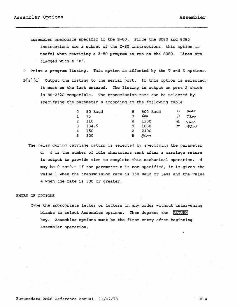
assembler mnemonics specific to the Z-80. Since the 8080 and 8085
instructions are a subset of the Z-80 instructions, this option is
useful when rewriting a Z-80 program to run on the 8080. Lines are
flagged with a "P".
P Print a program listing. This option is affected by. the T and E options.
B[s][d] Output the listing to the serial port. If this option is selected,
it must be the last entered. The listing is output on port 2 which
is RS-232C compatible. The transmission rate can be selected by
specifying the parameter s according to the following table:
0 50 Baud 6 600 Baud c ~"()
1 75 7 '00 l) 72.G>o 2 110 8 1200 E 9'(J() 3 134.5 9 1800 1= /9~~O
4 150 A 2400 5 300 B ~o
The delay during carriage return is selected by specifying the parameter
d. d is the number of idle characters sent after a carriage return
is output to provide time to complete this mechanical operation. d
may be 0 to-9.·- If the parameter n is not specified, it is given the
value 1 when the transmission rate is 150 Baud or less and the 7alue
4 when the rate is 300 or greater.
ENTRY OF OPTIONS
.Type the appropriate letter or letters in any order without intervening
blanks to select Assembler options. Then depress the (RETURNI key. Assembler options must be the first entry after· beginning
Assembler operation.
Futuredata AMDS Reference Manual 12/07/78 8-4

Specifying Assembler Files
Assembly Begins.
SPECIFYING ASSEMBLER FILES
Assembler
After the assembler options are entered, the assembler will display
the message SPECIFY INPUT FILE. Type the file name (which must have an "s"
attribute) and depress the ~TURNI key.
M option If the M option was selected, the message SPECIFY MACRO
LIBRARY will be displayed. Enter the name of the file on which the library
resides. (The file must have an "s" attribute.)
o option If the 0 option was selected, the message SPECIFY OBJECT
FILE i3 displayed. Enter the file name. The file may be created upon entry
to the assembler by prefixing the name with N: (See page 6-4). An object
file must have an "0" attribute. If the file is created on entry to the
assembler, it will be given this attribute.
ASSEMBLY BEGINS
Pass 1 After the last file name is entered, assembly begins. State
ments are processed in 2 passes. On the first pass, the asser.~ler assigns
values to symbolic labels and stores a symbol table. The message PASS 1 is
displayed.
Pass 2 During pass 2 the assembler analyzes each statement on the
input file and generates binary. If the assembler recognizes errors, they
are flagged and no binary is generated for that statement.
Stopping Assembly During assembly, pressing the IRETURN key causes
the assembler to pause and display the message RESTART? To abort the
assembly, type Y. To continue the assembly, depress the IRETURij key.
Futuredata AMOS Reference Manual 12/07/78 8-5

Assembler statement Syntax
Statement Fields Assembler
Assembly language programs are composed of three types of statements:
instruction mnemonics, assembler directives, and comment statements. Each
statement is one line of a maximum of 80 characters.
Statements are made up of four components or fields, as shown below.
Each field is separated from the next on the line by a blank space or series
of blanks.
Label Field The label field of a statement may contain a symbolic
name which is used to reference the statement from other statements, or
which will be assigned a value by an EQU directive. This field is optional.
If included, it must begin in the first character position on the line.
Operation Code Field The operation code (also called opcode) field
contains either a microprocessor instruction mnemonic or an assembler
directive. This field must always be present unless the entire line is a
comment. See Assembler Comments, page 8-14. Operation code fields must
begin in the second character position on the line or later, and must be
six characters or shorter.
Operand Field This field contains additional parameters called
operands associated with the mnemonic or directive in the operation code
field. Operands are not always required.
Comment Field The comment field is the last field. It is not
processed by the assembler but is printed or displayed in the program
listing. This field allows the programmer to document the action or purpose
of the statement. (Note that there is also a comment statement, which
occupies an entire line~ See Comment Statement, page 8-1~) If the operand
field is absent, and the operation code field allows optional operands, the
first character of a comment field should bea semicolon, to avoid ambigu
ity. A semicolon terminates assembler processing on the line in which it
appears.
Statement Diagram Assembler statement fields are represented on
later pages by the following diagram. The field being described is in bold.
label opcode operand comment
Futurerlata AMOS Reference Manual 12/07/78 8-6

Assembler Statement Syntax
Label Field Assembler
label opcode operand comment
A label may be invented and included on statements which must be
referenced by other statements in the program. Labels are optional and
should be used only where needed.
The EQU directive assigns a value to a label.
Label Name Conventions Labels must be 1 to 8 characters long and
begin with a letter. Characters in a label after the first must be letters
or numbers.
Labels may not be the same as the mnemonics used for microprocessor
instructions, registers, or condition codes. See the appropriate Futuredata
microprocessor reference manual for reserved names. Labels may also not be
the same as assembler directives.
Assembler Processing During assembly, a value is assigned to each
symbol.
In absolute program segments, the value assigned is the absolute
address of the memory location in which the instruction will be stored.
In relocatable program segments, the value assigned to a label is the
local address within the segment. (When the segment becomes part of a
program, the absolute memory address of the first word of the segment is
added to the local address of the label.)
When the assembler directive EQU is used, the label is assigned the
value of the operand field. This directive is described on page 8-16.
Symbol Table The assembler writes each label name, the address of
the label, and other information in a symbol table. Label names are
represented in ASCII. Each character of a label name requires one byte of
memory; short labels conserve memory space.
Futuredata AMDS Reference Manual 12/07/78 8-7

Assembler Statement Syntax
Operation Code Field
label opcode operand comment
Assembler
The opcode is a 3 or 4 character microprocessor instruction mnemonic
or an assembler directive of up to six characters. All instruction
mnemonics are those assigned by the microprocessor manufacturer. Each
mnemonic causes the assembler to generate one to three bytes of binary.
Refer to this manual for all information on assembler directives.
Futuredata AMOS Reference Manual 12/07/78 8-8

Assembler Statement Syntax
Operand Field Assembler
label opcode operand comment
The operand field contains operands which may be required in
instructions or assembler directives. Each operand is separated by a comma.
~. blank space terminates the operand field. If a blank is inad
vertently included in the field, the rest of the line after the blank will
be treated as a comment.
OPERAND TYPES
Five types of operands are used in the operand field: decimal
constants, hexadecimal constants, ASCII character constants, symbolic
labels, an asterisk used as a symbol for the address of the first byte of
the statement in which it appears, and expressions combining the previous
types.
Hexadecimal Constants Hexadecimal constants are made up of the
hexadecimal digits 0 to 9 and A to F. The digits must be enclosed in single
quotes. An X must prefix the first quote.
Single byte constants may be 1 or 2 digits. Two byte (address)
constants may be 1 to 4 digits in length. When less than the maximum
number of digits are used, the constant is treated as if leading zeroes
were supplied.
Examples of single byte hexadecimal constants are:
X'l' (same as X'Ol')
X'A3'
Examples of two byte (address) constants are:
X'103'
X'BF2A'
(same as X'Ol03')
Decimal Constants Decimal constants are numbers made up of the
digits 0 to 9. Single byte decimal constants may range from 0 to 255. Two
byte decimal constants may range from 0 to 65,535.
Futuredata &~S Reference Manual 12/07/78 8-9

Assembler Statement Syntax
Operand Field Assembler
ASCII Character Constants Each character of a character constant is
given an eight bit value defined by the American Standard Code for Informa
tion Interchange (ASCII). The high order bit is always zero. Examples are:
'ABC' f f ~
is equal to X'4l4243'
(blank) is equal to X'20'
Symbolic Address Labels Values assigned to address labels are listed
in a symbol table by the assembler during Pass 1, as is discussed under
Label Field, Page 8-16.
Symbolic Address Labels During assembly, each statement is scanned
and all address labels are listed in the symbol table with their assigned
values. (See page 8-16 for a discussion of labels. This is accomplished
during pass 2 of the assembler. During pass 2 the value assigned to a label
is substituted wherever it occurs as an operand.
Asterisk Parameter (*) An asterisk used as an operand causes the
assembler to substitute the value of the location counter at the first byte
of the statement in which the asterisk occurs.
Futuredata AMOS Reference Manual 12/07/78 8-10
Assembler Statement Syntax
Expressions in Operands Assembler
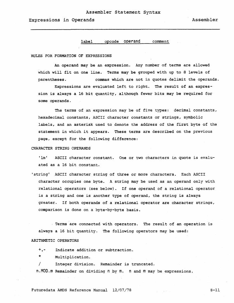
label opcode operand comment
RULES FOR FORMATION OF EXPRESSIONS
An operand may be an expression. Any number of terms are allowed
which will fit on one line. Terms may be grouped with up to 8 levels of
parentheses. commas which are not in quotes delimit the operands.
Expressions are evaluated left to right. The result of an expres
sion is always a 16 bit quantity, although fewer bits may be required for
some operands.
The terms of an expression may be of five types: decimal constants,
hexadecimal constants, ASCII character constants or strings, symbolic
labels, and an asterisk used to denote the address of the first byte of the
statement in which it appears. These terms are described on the previous
page, except for the following difference:
CHARACTER STRING OPERANDS
'1m' ASCII character constant. One or two characters in quote is evalu
ated as a 16 bit constant.
'string' ASCII character string of three or more characters. Each ASCII
character occupies one byte. A string may be used as an operand only with
relational operators (see below). If one operan~ of a relational operator
is a string and one is another type of operand, the string is always
greater. If both operands of a relational operator are character strings,
comparison is done on a byte-by-byte basis.
Terms are connected with operators. The result of an operation is
always a 16 bit quantity. The following operators may be used:
ARITHMETIC OPERATORS
+,
* Indicate addition or subtraction.
Multiplication.
/ Integer division. Remainder is truncated.
n.MOD.m Remainder on dividing n by m. nand m may be expressions.
Futuredata AMDS Reference Manual 12/07/78 8-11

Assembler Statement Syntax
Expressions in Operands Assembler
LOGICAL OPERATORS
.AND. Bit by bit logical AND
.OR. Bit by bit logical OR
.NOT. Complements each bit of the following one byte operand •
. XOR. Performs bit by bit exclusive or operation (a or b but not both)
REGISTER SHIFT OPERATORS
.SHL.n Shifts the previous one-byte operand or the lower byte of a two-byte
operand or expression n bits to the left. The leftmost n bits are
lost. n may be an expression. "
.SHR.n Shifts the previous one-byte operand or expression right n bits.
This is an arithmetic right shift. The highest order bit is
considered the sign bit and is not shifted or changed. If the
highest order bit is a one, ones are shifted into the bit positions
vacated by the right shift. If the highest order bit is a 0, zeroes
are shifted into the vacated bit positions. The rightmost n bits are
lost.
RELATIONAL OPERATORS
n=m Compare operator. If n is equal to m, 16 bit result is set to an
integer one. If not equal, the result is zero.
n>m If n is greater than m, the result is set to an integer one. If not
greater, the result is zero.
n<m n>=m n<=m
Less than operator. True is integer one. False is zero.
More than or equal to. The > and = may be interposed.
Less than or equal to.
BYTE EXTRACTION OPERATORS
The high or low order 8 bits of an expression may be extracted for
use as a parameter by enclosing the expression in parentheses and prefixing
wi th H (high) or L (los). These ope'rators are used when an expression,
Futuredata AMDS Reference Manual 12/07/78 8-12
Assembler Statement Syntax
Expressions in Operands Assembler
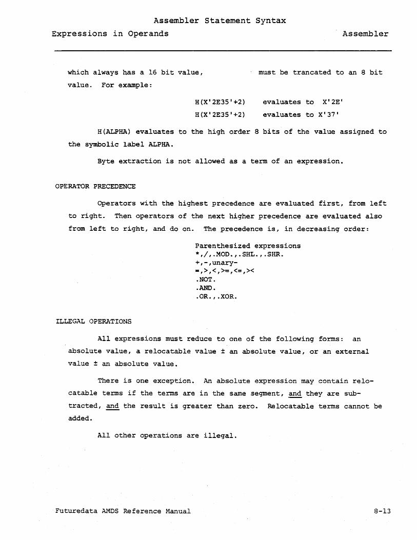
which always has a 16 bit value,
value. For example:
. must be trancated to an 8 bit
H(X'2E3S'+2)
H(X'2E35'+2)
evaluates to X'2E'
evaluates to X'37'
H{ALPHA) evaluates to the high order 8 bits of the value assigned to
the symbolic label ALPHA.
Byte extraction is not allowed as a term of an expression.
OPERATOR PRECEDENCE
Operators with the highest precedence are evaluated first, from left
to right. Then operators of the next higher precedence are evaluated also
from left to right, and do on. The precedence is, in decreasing order:
ILLEGAL OPERATIONS
Parenthesized expressions *,/,.MOD.,.SHL.,.SHR. +,-,unary-=,>,<,>=,<=,>< .NOT . • AND • . OR. , .XOR.
All expressions must reduce to one of the following forms: an
absolute value, a relocatable value ± an absolute value, or an external
value ± an absolute value.
There is one exception. An absolute expression may contain relo
catable terms if the terms are in the same segment, and they are sub
tracted, and the result is greater than zero. Relocatable terms cannot be
added.
All other operations are illegal.
Futuredata AMOS Reference Manual 8-13

Assembler Comments Assembler
COMMENT FIELDS
label opcode operand comment
The comment field starts after at least one blank space after the
operand field. This field is not processed by the assembler, but is printed
or displayed in the program source listing. Comments fields are used to
document the action or purpose of the statement in which they appear.
A semicolon anywhere on a line, but not within quotes, also
terminates assembler processing and should be used wherever there could be
ambiguity. For example, if the operand field is absent, and the operation
code field allows optional operands, a semicolon should be used before a
comment so that the comment is not processed as an operand.
COMMENT STATEMENTS
If there is an asterisk in the first character position on a line,
the entire line will be treated as a comment. Comment statements are useful
for documentation which requires more space than is available in a comment
field.
A line which has a semicolon as the first character (but in any
character position) is also processed as a comment statement.
Comment statements which are not inside macro definitions will
terminate reading of a macro library.
Futuredata AMDS Reference Manual 12/07/78 8-14

Assembler Directives
Segment Control Directives
ORG {expression}
Assembler
The ORG (origin) directive specifies the location in memory at which
subsequent statement are assembled. The expression must be absolute if it
is an absolute program segment and relocatable if it is in a relocatable
segment.
ASEG
The ASEG directive defines the beginning of an absolute program
segment. The assembler begins an absolute program segment at location zero
or at a location defined in an ORG directive. After intervening relocatable
segments (RSEG's), the ASEG directive will reset the location counter to one
plus the address of the end of the previous absolute segment.
RSEG trs.eg-name}
The RSEG directive defines a relocatable program segment. Up to 8
segments are allowed in an assembly, each identified by a unique name in the
operand field. A previous RSEG may be started again where it was left off
by another RSEG directive with the previous name
GLBL {label}[,label] ...
The GLBL directive is used to list all the external references and
entry points in an assembly. There may be a maximum of 255 external
references.
Futuredata AMDS Reference Manual 12/07/78 8-15
Assembler Directives END Directive lrequiredl
EQU Directive Assembler
END [expression]
The END directive terminates assembler operation. It must always be
the last statement in a program.
The expression specifies a program entry point -at which execution
will begin.
{label} EQU {expression}
The EQU directive assigns a value to a symbolic name. The symbol in
the label field is assigned the value of the exp~ession in the operand
field. The expression is evaluated during pass 1 of the assembler. The
symbol name may be referenced in the operand fields of statements occurring
before and after the EQU directive. However, -symbols in the expression
in the operand field must have been previously defined.
Futuredata AMOS Reference Manual 12/07/78 8-16

Assembler Directives
Data Block Directives Assembler
[1 abe 1 ] DC {operand}[,operand] ...
The DC directive is used to place data in memory, beginning at the
value in the location counter. Multiple operands are stored in successive
memory locations.
There are three ways that operands can be evaluated: 1) The value
of an expression is truncated to the lower eight bits and is stored in one
byte of memory. 2) An ASCII character string is stored one byte per
character. The string is enclosed in single quotes. A single quote within
the string is represented by two single successive quotes. 3) The 16 bit
value of an expression is stored in two succeeding bytes. If the expression
is enclosed in parentheses and preceded by an A, the high order byte will
be stored before the low order byte. If an expression is enclosed in
parentheses and preceded by a B, the low order byte will be stored ahead of
the high order byte. Two-byte operands can be intermixed with single-byte
operands in the same DC statement.
LOC DC H(BETA),A(ALPHA+X'23')
DC 'ABC' 'D'
[label] DS {expression}
This directive reserves memory space. The number of memory locations
reserved is determined by the value of the expression.
It cannot be assumed that the contents of the memory locations
reserved is zero.
If a symbol name is used as the expression or a term of the expres
sion, it must have been previously defined.
Futuredata AMDS Reference Manual 12/07/78 8-17

Assembler Directives
Printer Control Directives Assembler
SPACE
EJE
This directive is replaced by a blank line in the listing. It is
used to improve readability. No operands are processed.
The eject directive causes the assembler to skip to the top of the
next page. It is used to improve readability. No operands are processed.
PRINT OFF This directive suppresses printing of all following source lines.
The directive itself is not printed.
PRINT ON All source lines are listed except 1) lines in a macro, 2) lines
skipped due to conditional assembly directives, 3) the conditional
directives themselves. Lines are printed after set substitution takes
place.
PRINT GEN This directive operates the same as PRINT ON except that it also
causes lines in a macro to be printed. Lines in a macro are printed after
para~eter substitution takes place. Lines are printed after set symbol
substitution takes place.
PRIUT ALL This directive causes prin~ing of all source lines including those
skipped due to conditional assembly directives. Conditional assembly
directives themselves are printed. Lines skipped will have no location
counter value or object code printed. Lines are printed after set symbol
and macro parameter substitution takes place.
Futuredata AMOS Reference Manual 12/07/78 8-18

Messages
INVALID LABEL
INVALID OPCODE
INVALID OPERAND
IMMEDIATE VALUE >127 OR <-128
RELATIVE JUMP OUT OF RANGE (Z-80 only)
RELATIVE JUMP TO EXTERNAL SYMBOL <Z-80 only)
RELATIVE JUMP TO DIFFERENT RSEG (Z-80 only)
DUPLICATE SYMBOL
INVALID FORWARD REFERENCE
UNDEFINED SYMBOL
EXPRESSION HAS MORE THAN 1 RELOCATABLE FACTOR
SYMBOL TABLE OVERFLOW
MORE UNPRINTABLE ERRORS
SOURCE LINE TOO LARGE - TRUNCATED
UNDEFINED SET SYMBOL
INVALID MACRO PARAMETER NAME
MISSING ENDM
MACRO DEFINITION OUT OF PLACE
MISSING ENDIF
MISSING ENDDO
EXITM OUT OF PLACE
ENDM OUT OF PLACE
OPERAND LONGER THAN 32 CHARS
OVER 255 EXTERNALS
ERROR WHILE WRITING OBJECT FILE
MACRO NESTING EXCEEDS 127
MISSING END-
ENDDO OUT OF PLACE
ENDIF OUT OF PLACE
ELSE OUT OF PLACE
Futuredata AMOS Reference Manual 12/07/78
Assembler
8-20

Section 9
Macros & Conditional Assembly
MACROS
The macro facility allows a user to define an opcode which causes a
series of instructions to be assembled. For example, using the 8080, the
following series of instructions will add 10 to the Hand L registers,
using only the A register.
MOV A,L ADI 10 MOV L,A MOV A,H ACI a MOV H,A
If there are many such sequences in a program, it will be more
efficient (in time and disk space) and less error prone to define a macro
that will cause the sequence of instructions to be assembled whenever its
name appears in the opcode field:
ADDla MACRO A,L MOV A,L ADI 10 MOV L,A MOV A,H ACI a MOV H,A ENDM
The macro definition is begun by the MACRO pseudo-ope The label
field of the MACRO pseudo-op defines the name of the macro, in example 1,
ADDla. Statements following the MACRO pseudo-op represent the body of the
macro definition. These statements will be processed by the assembler
when the macro name occurs in the opcode field (when the macro is "called").
The ENDM pseudo-op ends the macro definition. The macro definition must be
placed at the beginning of the assembler source file, only the EJE, SPC,
and PRNT pseudo-ops may occur before the macro definitions.
Futuredata AMOS Reference Manual 12~a7-78 9-1

Macros Macros & Conditional Assembly
Macro Library All macro definitions must be placed at the beginning
of the source input file. However, by specifying tile M option, a second
source file of macro definitions may be included in the assembly. As in
the main input file, the first statement other than EJE, SPC. and print
which is not in a ma~ro definition will terminate reading of macro /
definitions.
Duplicate Macro Definitions If two macros with the same name are
defined, the last macro definition read will be the one used. Thus macro
definitions in the main source file take precedence over macro definitions
in the macro library.
Macro Calls Within Macros A macro definition may include a state
ment which calls another (or the same) macro. These calls may be nested to
any level (depending on the symbol table space available). A macro defini
tion may not have another macro defined in its body.
EXITM Statement When processed. the EXITM statement causes
immediate termination of the current or named macro. The next statement
processed will be the first one following the macro call. The syntax is:
EXITM [macro-name]
Note that no label is allowed.
Macro Parameters Obviously, a macro definition like ADDlO is of
limited use. How many times would you add the number 10 to the H and L
registers? It is much more likely that similar rather than identical
sequences of instructions occur in a program. Allowing a macro definition
to have variables that may have various values when the macro is called is
one way of doing this. For example, if we make the actual value added to
the H and L registers a macro parameter, the user can define a macro that,
when call.ed, will generate statements that will add any number from 0 to 255
to the H and L registers:
Futuredata AMOS Reference Manual 12-07-78 9-2

Macros Macros & Conditional Assembly
ADDX MACRO NUM MOV A,L ADI &NUM
MOV L,A MOV A,H ADI 0 MOV H,A ENDM
If the macro is called in the following way:
"LHLD
ADDX SHLD
VALADR" 5 VALADR
The following statements will be generated:
LHLD VALADR MOV' A,L ADI 5 MOV L,A ACI 0 MOV H,A SHLD VAIADR
What happens is that in the macro definition, the names of all the
macro parameters are listed (separated by commas) in the operand field of
the MACRO pseudo-op. When the macro is called, the actual values to be
used are listed in the operand field of the calling statement (separated by
commas). Then, wherever a macro parameter name a~pears in the body of the
macro definition, preceeded by an ampersand, the actual value of the para
meter is substituted in place of the ampersand and name. Note that this
substitution is done character for character (up to 32 characters per
parameter). The macro parameters need not be numeric. Also, the substi
tution may occur in the label, opcode, operand, comment, or any combination
of fields. For example, for the macro definition:
SAVEA MACRO & TYPE ENDM
Futuredata AMOS Reference Manual 12-07/78
TYPE,LOC &LOC
9-3
!v!acros Macros & Conditional Assembly
The call:
SAVEA STA,VAL
will result in:
STA VAL
while the call:
SAVEA STAX,D
will result in:
STAX D
Macro Parameter Delimiters As stated, when a macro is called, the
actual values of the parameters are listed in the operand field of the
calling statement, separated by commas. However, commas and blanks may
exist in a parameter if they occur between quotes. Also, there must be
an even number of quotes in any parameter. The following are examples of
valid parameters:
20 X' 40 I
I A,B "+' B ,C' AIIC
ABC
Concatenating Parameters In the previous example, the value of
parameter INDX, was ap~ended in the right of the characters AB simply by
wri ting the parameter name, preceeded by an ampersand, to the immediate
right of the characters AS: AB&INDX. If, also, the user wished to append
an A to the right of the value of parameter INDX, a problem would have
arisen:
JP AB&INDXA
The macro processor would have interpreted this to mean: Substitute
the value for parameter INDXA. To solve this problem, the macro processor
recognizes a parameter name delimiter: ! whose only function is to indicate
the end of a parameter name. The correct way to append an A to the right
of the value of parameter INDX is:
Futuredata AMOS Reference Manual 9-4

Macros Macros & Conditional Assembly
JP AB&INDX!A
JP ABOOOOlA
Note that is appears anywhere other than after a macro parameter
(or a set symbol), it will be treated as a normal character.
Literal Ampersand Since the ampersand signals the macro processor
to substitute a parameter value, a special set of characters is needed to
tell the macro processor that rather than substituting, an actual ampersand
character is wanted. For example, if the user wants to put an ampersand
into the A register, he might think to write:
MVI A,'&'
However, for reasons explained under Advanced Considerations, when
ever a single ampersand is wanted in the generated statement, four
ampersands must be written in the actual source:
MVI A,' &&&& '
Generating Unique Labels A macro call may generate statements with /
labels. For example, the following definition: (to makeD,E=absolute value /
of 0, E)
ABSD MACRO MOV A,D ORA A
JP ENDABSD CMA
MOV D,A MOV E,A CMA
MOV E,A INX 0
ENDABSD EQU * ENDM
The first time ASsn is called, label ENDABSD will be defined.
Unfortunately, the second time ABSD is called, ENDABSD will also be defined
and a duplicate definition error will result. What is needed is a way to
generate a unique label each time the .macro is called. The Futuredata
Futuredata AMOS Reference Manual 12-07/78 9-5

Macros Macros & Conditional Assembly
Macro Assembler provides this capability by pre-defining a special
parameter - lNDX - which will always have a unique 5 digit numeric value
each time a macro is called. The macro ABSD may now be defined in the
following way:
ABSD MACRO MOV A,D ORA A JP AB&lNDX w'1A MOV O,A MOV A,E CMA MOV E,A lNX 0
AB&lNDX EQU * ENDM
Assuming that this is the only macro defined and that there are
exactly two calls made, the first call defines the label ABOOOOI and the
second call defines the label AB00002. Note that a label on the actual
macro call statement takes on the current location counter value at the
beginning of the call.
Futuredata AMDS Reference·Manual 12/07/78 9-6

Conditional Assembly Macros & Conditional Assembly
CONDITIONAL ASSEMBLY
These statements allow a programmer to selectively assemble state
ments in a source file. For example, if a programmer did not know whether
the program was going to be used with a tape or disk, both the calls to the
tape subroutine and disk subroutine could be included in the source file,
and conditional statements used to actually assemble the one needed:
DEVICE DEFG
IF LHLD CALL ELSEIF LHLD CALL ENDIF
'TAPE'
• &DEVICE'=' TAPE' TAPEFCB TAPEIO , &DEVICE' =' DISK' DISKFCB DISKIO
More often, conditional statements will be used to implement more
complex macros. For example, the ADDX macro defined earlier could be ex
panded to add a number between 0 and 255 to the BO, DE, or HL registers:
ADDXY MACRO REG,NUM IF ' ®' =' BC'
REGH DEFL ' ~' REGL DEFL 'c'
ELSEIF ' ®' =' DE' REGH DEFL I D' REGL DEFL 'E'
ELSE REGH DEFL 'H I
REGL DEFL I L I
ENDIF MOV A,®L ADI &NUM MOV ®L,A MOV A,®H ACI 0 MOV ®H,A ENDM
Futuredata AMOS Reference Manual 12/07/78 9-7

Conditional Assembly Macros & Conditional Assembly
ADDXY could be expanded further to add a number between 0 and 65537
to the BC, DE, or HL registers:
ADDXY MACRO REG,NUM IF '® '=' BC'
REGH DEFL '""S • ""
REGL DEFL 'e" ELSEIF '®'='DE'
REGH OEFL '0' REGL DEFL '"E'
ELSE REGH DEFL 'H' REGL DEFL '"L'
ENDIF NUMH DEFL &NUM/256 NUML DEFL &NUM.MOD.256
MOV A,®L ADI &NtJML MOV ®L,A MOV A,®H ACI &NUMH MOV ®H,A ENDM
One of the more common uses of conditional statements is to generate
tables that would be long, tedious, and error prone to enter by hand. The
following example generates a table that could be used to check whether a
character is numeric:
TABLE CHAR
CHAR
EQU DEFG DO IF DC ELSE DC ENDIF DEFG ENDDO
* 0 256 &CHAR< '0' .OR.&CHAR>' 9' 0
X' FF I
&CHAR+l
Set Symbols Set symbols (and macro parameters) are the variables used
by the conditional statements. Their value may be either numeric (0 to
65537) or a character string (0 to 32 characters long). The values are set
by using the DEFG (define global) and DEFL (define local) statements.
Futuredata AMOS Reference Manual 12/07/78 9-8

Conditional Assembly Macros & Conditional Assembly
DEFL Statement This statement is used to define (and redefine) a
local set symbol." A local set symbol is only known in the macro in which
it is defined. A set symbol of the same name defined in a different macro
is actually a different set symbol. The syntax is:
{set-symbol-name} DEFL {expression}
or:
{set-symbol-name} DEFL { 'string' }
If quotes are placed around the operand, it is treated as a
character string and may be a maximum of 32 characters long. Quotes
embedded in the string must be doubled. They are, however, stored as
double, not single, quotes. If quotes are not placed around the operand,
it is treated as an integer expression. Labels may appear in the
expression only if they have been previously defined.
Note that when defining a set symbol, an ampersand must not preceed
the name in the label field. When using the set symbol, an ampersand must
preceed the name.
DEFG Statement This statement is used to define (and redefine) a
global set symbol. A global set symbol is known in all macros unless a
local set symbol of the same name is defined in a'particular macro. In
this case, the global set symbol will become unknown, in that particular
macro only, as soon as the like named local set symbol is defined. The
syntax is:
{set-symbol-name} DEFG {expression}
or:
{set-symbol-name} DEFG {"stringl}
Futuredata AMDS Reference Manual 12/07/78 9-9

Conditional Assembly Macros & Conditional Assembly
If quotes are placed around the operand, it is treated as a
character string and may be a maximum of 32 characters long. Quotes
embedded in the string mus·t be doubled. If quotes are not placed around
the operand, it is treated as an integer expression. Labels may appear in
the expression only if they have been previously defined.
Note that when defining a set symbol, an ampersand must not preceed
the name in the label field. When using the set symbol, an ampersand must
preceed the name.
IF Block An IF block begins with an IF statement and ends with an
ENDIF statement. IF blocks may be nested within IF blocks or DO blocks to
any level.
IF Statement The IF statement begins an IF block. It may have an
optional name in the label field which may be referred to in the EXITIF
statement. If the expression in the operand field of the IF statement is
non-zero, the statements following the IF statement up to the first
ELSE, or EXITIF statement at the same nesting level will be processed. If
the expression is zero, the statements following the IF up to the first
ELSEIF, ELSE, or ENDIF statement at the same nesting level will be ignored.
The syntax is:
[if-black-name] IF {exp~ess;on}
ELSEIF Statement The ELSEIF statement is used in conjunction with
an I~ :tatement to test an alternate condition without going to a deeper
nesting level. If the expression in the IF statement was ° and the
expressions in all previous ELSEIF statements at this nesting level were 0,
and the expression in this ELSEIF statement is non-zero, statements up to
the next ELSEIF, ELSE, or END IF statement at this nesting level will be
processed. The syntax is:
ELSEIF {expression}
Note that no label is allowed.
Futuredata AMOS Reference Manual 12/07/78 9-10

Conditional Assembly Macros & Conditional Assembly
ELSE Statement The ELSE statement is used in conjunction with an IF
statement to indicate the last alternative. It is identical to:
ELSEIF 1
That is, if the expressions in the IF statement and all subsequent
ELSEIF statements at this nesting level are 0, the statements after the
ELSE statement up to the closing ENDIF statement are processed. The
syntax is:
ELSE
Note that no label or operand is allowed:
EXITIF Statement The EXITIF statement when processed will cause all
statements up to the closing ENDIF statement in the named or current IF
block to be ignored. The syntax is:
EXITIF' [if-black-name]
Note that no label is allowed.
ENDIF Statement The ENDIF statement terminates an IF block. The
syntax is:
ENDIF
Note that no label or operand is allowed.
DO Block A DO block begins with a DO statement and ends with an
ENDDO statement. It causes repetitive assemb~y of the statements within
the block. DO blocks may be nexted within IF blocks or DO blocks to any
level.
DO Statement The DO statement begins a DO block. It may have an
optional name in the label field which may be referred to 'in the EXITDO and
NEXTDO statements. The expression in the operand field is evaluated ONCE
at the entry to the DO block and is stored as the DO COUNT - the number of
Futuredata AMOS Reference Manual 12/07/78 9-11

Conditional Assembly Macros & Conditional Assembly
times the statements within the block are processed. The syntax is:
[do-black-name] DO [expression]
If the expression is omitted, the block will be processed 65538
times (essentially indefinitely).
EXITDO Statement The EXITDO statements, when processed, causes the
assembler to immediately terminate processing statements in the current or
named 00 block and begin at the first statement after the closing ENDDO
statement. The syntax is:
EXITDO [do-block-name]
Note that no label is allowed.
NEXTOO Statement The NEXTDO statement, when processed, causes the
assembler to immediately begin processing the next iteration of the current
or named DO block. That is, if this is not the last iteration, the next
statement processed will be the first statement after the DO statement.
The syntax is:
NEXTDO [do-black-name]
Note that no label is allowed.
ENnDO Statement The ENDDO statement terminates a 00 block. The
syntax is:
ENODO
Note that no label or operand is allowed.
Futuredata AMOS Reference ~anual 12/07/78 9-12

Conditional Assembly Macros & Conditional Assembly
SUBSTR Statement The SUBSTR (substring)statement assigns a part of
a string to a set· symbol. If the set-symbol has not been previously
defined, a new local set-symbol will be defined. The syntax is:
{set-symbol-name} SUBSTR {expression-a},{expression-b},{"string l}
express;on-a defines the beginning character position of the sub
string. The first character is position 1. expression-b defines the
length of the substring. If expression-b is 0, the substring will begin
with the character defined by expression-a and continue to the end of the
string.
LENGTH Statement The LENGTH statement assigns the length of a
string to a set symbol. If the set-symbol has not been previously defined,
a new local set-symbol will be defined. The syntax is:
{set-symbol-name} LENGTH 'string l
Futuredata AMOS Reference Manual 12/07/78 9-13

Advanced Considerations Macros & Conditional Assembly
ADVANCED CONSIDERATIONS
Each source line is scanned twice before processing for ampersands
which signal set symbol or macro parameter substitution. During each scan
any set symbol names preceeded by ampersands have their values substituted
for the ampersand and name. Any doubled ampersands are replaced by a single
ampersand. This allows the following capabilities:
Subscripted Set Symbols The following statement will define a set
symbol whose name is based on the value of another set symbol:
A&l DEFL 'A'O
If &1 has the integer value 4, the set symbol A00004 will be defined
to have the value A. The following statement uses the set symbol:
MVI B, '&&A&I"
On the first scan, the && is replaced by & and &1 is replaced by
00004 leaving:
MVI B, '&A00004'
On the second scan, &A00004 is replaced by A leaving:
MVI B, 'A'
By varying the value of the set symbol I, set symbols may be defined
and referenced which are indexed using I as a subscript.
Indirect Set Symbols The following statements will define a set
symbol whose value is the name of another set symbol:
A
B DEFG OEFG
'ABC' 'A'
The following statement will use the set symbol B as an indirect
reference to the value of set symbol A:
IF O'&&&B'o= 'ABC'
On the first scan, the first two ampersands will be replaced by a
single ampersand and &B will be replaged by A leaving:
IF '&A= 'ABC'
Futuredata AMOS Reference Manual 12/07/78 9-14
Advanced Considerations Macros & Conditional Assembly
On the second scan, &A will be replaced by ABC leaving:
IF . 'ABC' =tABC'·
Futuredata AMOS Reference Manual 12/07/78 9-15
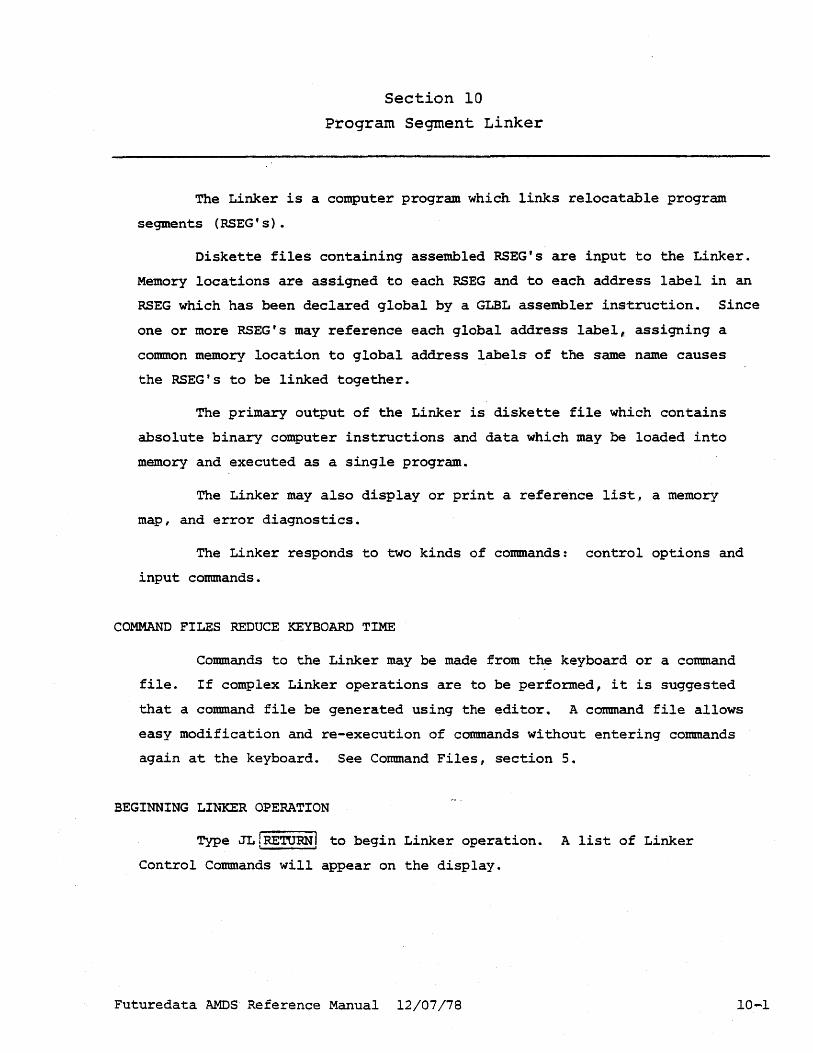
Section 10
program Segment Linker
The Linker is a computer program which links relocatable program
segments (RSEG's).
Diskette files containing assembled RSEG's are input to the Linker.
Memory locations are assigned to each RSEG and to each address label in an
RSEG which has been declared global by a GLBL assembler instruction. Since
one or more RSEG's may reference each global address label,. assigning a
common memory location to global address labels of the same name causes
the RSEG's to be linked together.
The primary output of the Linker is diskette file which contains
absolute binary computer instructions and data which may be loaded into
memory and executed as a single program.
The Linker may also display or print a reference list, a memory
map, and error diagnostics.
The Linker responds to two kinds of commands: control options and
input commands.
COMMAND FILES REDUCE KEYBOARD TIME
Commands to the Linker may be made from the keyboard or a command
file. If complex Linker operations are to be performed, it is suggested
that a command file be generated using the editor. A command file allows
easy modification and re-execution of commands without entering commands
again at the keyboard. See Command Files, section 5.
BEGINNING LI~lCER OPERATION
Type JL!RETURN! to begin Linker operation. A list of Linker
Control Commands will appear on the display.
Futuredata AMOS Reference Manual 12/07/78 10-1

Linker Control Options Linker
CONTROL OPTIONS
Option Letter
o
D
S
Action Taken by Linker
Write an absolute binary object file to diskette. This
option must be selected if the linked RSEG's are to be
executed. This option may be omitted if the Linker is
being run only to get display, printer, or serial port
output.
Only RSEG's which are specifically named in the command
file or by keyboard entry are input to the Linker;
others are deleted. If D is selected, unspecified RSEG's
are deleted from both the binary and display output.
The symbol tables (which may be placed at the end of
each RSEG by the assembler) are written at the end of
the absolute binary object file. These tables are
required for symbolic debugging. The 0 option must
also be selected when S is specified.
L Display the memory map and reference list.
P Print the memory map and reference list.
B[speed] [delay] Output the memory map and reference list to the serial
port. Speed is a number designating baud rate and
delay is a number designating the number of idle char
acters transmitted after each line. See Utilities,
Section 14. This must be the last entry.
PURPOSE
Linker control options specify combinations of input and output
available to the user.
EXPLANATION
Control options may be entered only immediately after the beginning
Linker operation. Each option is selected by typing the appropriate
letter. Multiple options may be selected by typing the corresponding
letters in any order without intervening blanks.
Futuredata AMOS Reference Manual 12/07/78 10-2

Linker Input Commands
COMMANDS
input-file-name [input-file-name]
[object-file-name]
#ORG {absolute-address}
{rseg-name-a} [,rseg-b] [rseg-name-c]
IIORS {absolute-addres~} rseg-name-d
lEND [global-name]
Notes:
Linker
Explanation
As many input files as needed may be
specified, one per depression of the
fRETURNI key.
One object file must be entered if the 0
control option was selected.
Specify the absolute address of the start
of the first RSEG which will be entered.
Then specify a list of RSEG's, as many as
desired, which will be loaded in the order
given starting at the address in the #ORG
statement.
More starting addresses, each with a list
of RSEG's, may be specified.
global-name is used as the entry point of
the program. If none is specified, the
first byte of the first RSEG will be the
entry point. Only one #END command can be
used.
1) If Linker control option D is not selected, all RSEG's which were not
specified in #ORG commands are included after the last named RSEG in
both the binary and display output.
2) If there is more than one RSEG of the same name in the input files
the first one encountered by the Linker will be used.
3) It is possible using #ORG commands to define the origin of an RSEG
at the location of a previous RSEG. If this is done, the overlaid
RSEG will be flagged by an "0" in the length column of the memory
map.
Futuredata AMDS Reference Manual 12/07/78 10-3
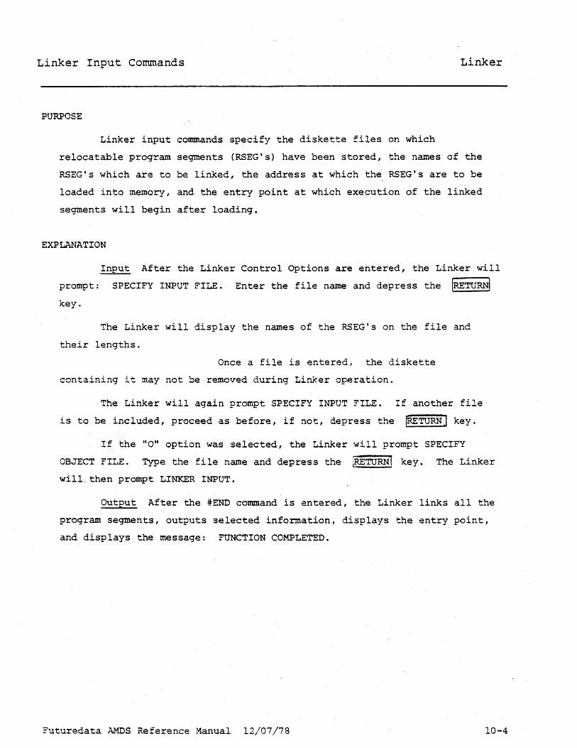
Linker Input Commands Linker
PURPOSE
Linker input commands specify the diskette files on which
relocatable program segments (RSEG's) have been stored, the names of the
RSEG's which are to be linked, the address at which the RSEG's are to be
loaded into memory, and the entry point at which execution of the linked
segments will begin after loading.
EXPLANATION
Input After the Linker Control Options are entered, the Linker will
prompt: SPECIFY INPUT FILE. Enter the file name and depress the IRETURNI key.
The Linker will display the names of the RSEG's on the file and
their lengths.
Once a file is entered, the diskette
containing it may not be removed during Linker operation.
The Linker will again prompt SPECIFY INPUT FILE. If another file
is to be included, proceed as before, if not, depress the IRETURN] key.
If the "0" option was selected, the Linker r,olill prompt SPECIFY
OBJECT FILE.. Type the file name and depress the iRETURN! key. The Linker
will. then prompt LINKER INPUT.
Output After the #END command is entered, the Linker links all the
program segments, outputs selected information, displays the entry point,
and displays the message: FUNCTION COMPLETED.
Futuredata AMDS Reference Manual 12/07/78 10-4

Memory Map Output
This is an. example of a Linker memory map:
FUTUREDATA LINKAGE EDITOR
":'CDF\ i~!3EO
(:,400 KE'y'E; 040B CIJU'· ... T 0414 INC l\)OO TEr'lF'
FILE
KE'{B. R COUNT. INC. R COUNT.
R
R
LENGTH
0001:: O(iG9 OOO~5
0001
Linker
1) Memory locations of the RSEG's are listed in the order in which they
were input to the Linker. If the operands' of the #ORG commands were
input in ascending order then the listed memory locations will also
be in ascending order.
2) The RSEG name, the name of the file from which the RSEG was taken,
and the RSEG memory length in hexadecimal are also listed.
3) If an RSEG was deleted (control option D was specified) the name of
the RSEG will appear in the memory map but the address will be
flagged with a "D".
4) If an RSEG is overwritten by another RSEG, the overwritten RSEG will
be flagged with an "0" in the memory map.. (See Linker Input
Commands. )
Futuredata AMOS Reference Manual 12-07-78 10-5

Reference List Output Linker
This is an actual example of a Linker reference list:
::: ~. It:': I J. _I ••
KE·YE:. f~:.
FIL.E CiJUN T. f,~
i:"~ L.E ~~i~·Ji='i F\:
F;~!:;EO
:<EYE:
OLOE:AL~:; KE"{ 1::
R:3EG COUNT TEt1P
OLCtE:AL~:;
COUNr
R:::;EO INC
I3LOI:;~L~=;
INC
ENfRY POINT 0000
ADOR LEi\~GTI·f
U400 0001::
t=iDDR. LENGTH i)40E: 0009 1.000 OOOi
0401:: COUNT 1
AD[lf~ L.Ei-iGTH ~:;4 i. 4 O(il)5
04i4 INCR
L I r'l I T
1) The Linker reference list shows each disk file from which RSEG's
were input,
2) the name of each RSEG,
3) the hexadecimal memory address of ~~e beginning of each RSEG,
4) the hexadecimal length of the RSEG.
5) The list also shows global address labels with the absolute memory
address which was assigned to each label.
6) The last line of the reference list is the entry point address at
which program execution will begin.
Futuredata .~~S Reference Manual 12-07-78 lO~6

Linker Error Messages Linker
NOT A RELOCATABLE FILE - The Linker input file was not created by
the Futuredata Relocating Assembler or the "Rn attribute has beer. changed
using the File Manager
PARM ERR ••• RESPECIFY - Syntax error in tbe Linker input.
(label) **DUPLICATE GLOBAL IN (filename) - The first occurrence of
a global label is used for address references. All additional definitions
are flagged as an error.
(label) **UNRESOLVED REFERENCE IN (filename) - The external
reference was not found in the global symbol table.
**DELETED RSEG REFERENCED IN (filename) - An RSEG which was not in
cluded is needed to resolve address references.
**RELOCATION ERROR IN (filename) - Input file was not correctly
assembled with the Futuredata Relocating dssembler.
**TABLE OVERFLOW - The Linker needs more memory.
**SYMBOL TABLE NOT FOUND IN (filename) - The symbol table was not
included when the program was assembled.
**SEQUENCE ERROR IN (RELOCATABLE FILE NAME) - records in (relocat
able file name) are not in proper order. Reassemble.
Futuredata AMOS Reference Manual 12-07-78 10-7

INTRODUCTION
Section 11
Symbolic Debugger
The Futuredata Debugger is called symbolic because memory locations
may be referenced by the symbolic address labels used in the program
being debugged.
The Debugger is an extremely powerful tool for finding and
correcting errors in a program. The Debugger allows the user to see and
change the contents of memory and registers. A program may be executed
beginning at any point at processor speed or may be executed one instruction
per keystroke. The user may set breakpoints which stop execution and return
control to the keyboard. Trace execution allows the user to view the state
of the program counter, registers, and status bits for the 20 instructions
executed prior to a breakpoint. Memory addresses may be referenced by the
address labels used in assembly language source programs. Sections of
memory may be write-protected.
Debugger Information Specific to a Microprocessor Information on
debugging which is microproce-sor dependent may be found in the micropro
cessor reference manual. For example, for the 8080 further information is
in the Debugger section of the Futuredata 8080 Reference Manual.
BEGINNING DEBUGGER OPERATION
Type JOIRETURN! to begin debugger operation.
Futuredata AMOS Reference Manual 12/07/78 11-1

Debugger Display Debugger
This is an ex~ple of the debugger display for the 8080:
Register Display The first line of the display shows the letters
assigned by the manufacturer of the microprocessor to the 8080 internal
registers.
The second line displays the contents in hexadecimal of the registers
and program status byte. These first two lines vary depending on the
microprocessor since the registers and letter designations vary.
The rest of the display is split into two halves which are separately
controlled by debugger commands.
Disassembly Display, left side. The left half shows 10 micropro
cessor instructions ..
The first column on the left shows the hexadecimal memory address of
the instruction. If a mu1tibyte instruction is used, ~~e address of the
Futuredata ~~s Reference ~anual 12/07/78 11-2

Debugger Display Debugger
first byte is displayed. The address is suffixed with an * if it is write
protected, or a + if it is in the user system during emulation.
The second and third columns show the assembly mnemonic assigned by
the microprocessor manufacturer to that instruction.
Disassembly is performed as though memory contained program. Since
disassembly may start at any byte in memory, and the memory locations may
contain data rather than program, the disassembly display may ~e meaning
less. It is up to the user to position the left half of the display so
that disassebmly starts at the first byte·o·f an instruction.
Memory Map, right side. The first column of the right side of the
display lists the hexadecimal address of the first of eight memory locations
on each line. If a location in memory is write protected it is suffixed
with an asterisk. If, during emulation, a location in memory is placed in
the user system, it is suffixed with a plus.
The next eight columns are the contents of memory in hexadecimal.
The first column is the contents of the addresses shown. The addresses of
the others may be obtained by counting.
The last column is the ASCII representation of 'the contents of each
of the locations in the memory map. This feature is useful if the contents
of the memory displayed is alphabetic data. If a byte does not contain a
printing ASCII character a dot is displayed.
Memory Pointers. These are tw~ pointers, one on each side of the
display, which point to the displayed contents of memory. These memory
pointers indicate the byte at which execution would begin after an execute
or single step command. The cursor address is also used as input by 3
other commands.
Command Entry Cursor There are two more pointers on the command
line. The blinking rectangle command entry cursor may be positioned in
front of either by depressing the tab key. When the blinking cursor is on
the left side, commands may be entered which affect only the left half of
the display. When the blinking cursor is on the right side, commands affect
that side. The side on which the cursor is located is called the active
side of the display.
Futuredata AMDS Reference Manual 12/07/78 11-3

Load Program (L) Debugger
COMMAND
L{file-name}[,[offset] [,symbol-table-address]]
file-name is the name of the absolute object file.
offset is a constant or expression which specifies the number of memory
locations to be added to the load address given in the object file.
If not specified, the offset value is zero. This parameter is used
in programming EPROM's. (See Section 14, EPROM programming.)
symbol-table-address is a constant or an expression which specifies the
beginning address at which the program symbol table is to be loaded.
Notice that if this parameter is specified, but the offset parameter
is not, the table parameter must be separated from file-name by two
commas. If symbol-table-address is not specified, the table will
not be loaded.
Note: This command will set the program counter to the entry point of the
loaded program.
PURPOSE
This command loads absolute binary object programs so that they may
be examined, changed, and executed using the Debugger.
EXPLANAT!ON
See page 11-20 for rules for formation of expressions. Symbols from
a previously loaded symbol table may be used as terms of an expression in
this command.
EXAMPLES
The following are legal forms of the Load command:
LPF!LE,lOB+F8,lOB+F8+3000 LCOUNTER"BOB8-AOF (no offset param) LCALC,lOOO (no symbol table)
Futuredata AMDS Reference Manual 12/07/78 11-4
Loading for Symbolic Debugging Debugger
Symbolic d~bugging requires that a symbol table which was generated
by the Assembler (S option), and output to a diskette file by the Linker (S
option), be loaded into memory by the Debugger (symbol-table-address
parameter) .
On completion of loading, the Debugger displays the hexadecimal
length of the symbol table. If there is insufficient memory for the symbol
table, or if the memory into which it would be loaded is write-protected,
the message PARTLY LOADED is displayed. Symbols which were loaded can be
referenced. In order to load the complete symbol table, it is necessary to
add more memory or specify a lower symbol table address.
To determine which symbols were loaded, position the display at an
address near the end of the symbol table. The names of the symbols are
shown on the. ri~ht side of the display as ASCII characters. Each entry in
the symbol table occupies 4 bytes past the last character of the symbol
name. (See the Assembler, Section 8, for a complete description of the
symbol table.)
Futuredata AMOS Reference Manual 12/07/78 11-5
Swap Command Cursor Debugger
COMMAND
ITABlsuccessive keystrokes swap the command cursor left and right.
PURPOSE
This command selects which half of the display the next command
will affect.
EXPLANATION
The Debugger display is formatted into two halves. Commands operate
on each half independently. The left half displays assembler mnemonics
obtained by disassembling the program in memory. The right half displays
memory addresses and the contents of each address.
Futuredata AMDS Reference Manual 12/07/78 11-6

Display Memory (D) Debugger
COMMAND
D{expression}
expression may be a constant, an arithmetic expression, an indirect address,
a relative address, a symbolic reference or a combination or the
above.
D($]
This form of the command returns the previous display to the screen.
PURPOSE
This command displays the contents of memory both in hexadecimal
(right side of display) and in microprocessor mnemonics obtained by
disassembly (left side).
EXPLANATION
For rules for formation of expressions, see page 11-20.
Futuredata AMOS Reference Manual 12/07/78 11-7

position Memory Pointer Debugger
COMMANDS
m advance 1 line
W back up 1 line
G advance 1 byte
G back up 1 byte
PURPOSE
These keys change the position of the memory pointer by one byte or
one line (eight bytes) .
EXPLANATION
The side of the display which is affected is indicated by the
position of the command cursor.
Futuredata AL~S Reference Manual 12/07/78 11-8

Store Data In Memory (S) Debugger
COMMAND
S{constant}[,constant].
The constants are stored beginning at the memory pointer address, one per
location.
con-stant is a one or two digit hexadecimal number or a single ASCII
character surrounded by single quotes. If a single digit is used, the
high order four bits stored will be zeroes'.
PURPOSE
This command stores data entered at the keyboard directly into
memory.
EXPLANATION
The side of the display at which data is stored in memory is
indicated by the rosition of the command cursor.
EXAMPLE
. SlE, 'A' , 'B'
This example stores the hexadecimal constant lE in the address
indicated by the memory pointer. The eight bit ASCII representation of
the letters A and B are stored one in each of the two succeeding memory
locations.
Futuredata AMOS Reference Manual 12/07/78 11-9

Store Data in Register (Z) Debugger
COMMAND
Z{reg=constant}[,reg=constant].
reg may be any register shown at the top of the display, except the program
counter.
If reg is an 8 bit register, constant may be a one or two digit hexadecimal
number or a single ASCII character surrounded by single quotes.
If a single hexadecimal digit is specified, the high order four bits
stored will be zeroes.
If reg is a 16 bit register, constant may be a one to four digit hexadecimal
number or one or two ASCII characters surrounded by single quotes.
If less than four hexadecimal digits or only one ASCII character is
specified, the high order bits stored will be zeroes.
PURPOSE
This command stores data entered at the keyboard directly into a
register.
EXPLANATION
If an attempt is made to set the program counter, the message SYNTAX
is displayed and no action is taken.
EXAMPLE (8080 microprocessor)
The command
ZSP=AIOO,B='H' ,e=3
stores the hexadecimal number AIDa in the stack pointer, a 16 bit register.
It also stores the hexadecimal number 48, which is the hexadecimal represen
tation of the character H in ASCII, in the B register. It stores hexa
decimal 03 in the C register.
Futuredata AMOS Reference Manual 12/07/78

Find Data in Memory (F) Debugger
COMMAND
F[constant] [,constant].
constant is a one or two digit hexadecimal number or a single ASCII
character surrounded by single quotes. If a single digit is used,
the high order four bits will be zeroes.
If no parameters are specified, the previous constant or constants specified
in an F command is used.
PURPOSE
The F command searches through memory, starting at the address of the memory
pointer on the active side of the display, for a match between the constants
specified and a byte or series of bytes in memory.
EXPLANATION
Each constant occupies one byte. A match occurs when ~~e bytes
specified in the F command are identical to a series of bytes in memory.
When a match is found, the F command positions the memory pointer at the
first byte of the match.
The F command begins searching for a matc~ at the memory pointer
address of the active side of the display.
Unless a match is found, the command searches to the end of memory
(FFF), begins searching again at the beginning of memory (000), and
continues to the memory pointer address, where is stops.
Futuredata AMOS Reference Manual 12/07/78 11-11

Set Breakpoint (BS)
Display Breakpoint (BD) Debugger
SET BREAKPOINT COMMAND
BS{n}
n is an integer between ° and 4.
If n = 0, the hardware breakpoint will be used.
PURPOSE
This command sets a breakpoint at the cursor address.
DISPLAY BREAKPOINT COMMAND
BD{n}
n is an integer between ° and 4.
PURPOSE
This command positions the memory cursor at the address of the
nth breakpoint.
EXPLANATION
See page 11-14 for an explanation of breakpoints.
Futuredata AMDS Reference Manual 12/07/78 11-12

Reset Breakpoint (BR)
Clear All Breakpoints
RESET BREAKPOINT COMMAND
BR
PURPOSE
(BC) Debugger
This command removes the breakpoint at the address indicated by the
memory pointer and restores the former instruction. If there is no break
point at this address, the message NOT ACTIVE is displayed and no action
is taken.
CLEAR ALL BREAKPOINTS
Be
PURPOSE
All breakpoints are removed and for.mer instructions restored.
EXPLANATION
See page 11-14 for an explanation of breakpoints.
Futuredata AMOS Reference Manual 12/07/78 11-13

Explanation of Breakpoint Commands Debugger
A breakpoint is a location is a program being debugged at which execution is stopped and control is returned to the Debugger. Breakpoints are useful for splitt~ng a program into pieces which may then be executed separately. This makes debugging a complex program a much more manageable job.
If n=O in the breakpoint set command, a hardware interrupt is used to return control to the Debugger. This is a hardware breakpoint.
If n is 1 to 4, a microprocessor interrupt instruction is used to return control to the Debugger. This is a software breakpoint. The numbering serves to uniquely identify each breakpoint.
When a software breakpoint is set,. a microprocessor interrupt instruction (hexadecimal F7 for the 8080, 3F for the 6800) is stored at the memory location of the breakpoint. This instruction replaces one of the instructions in the program, but since the last instruction of the piece of the program being debugged is just before the breakpoint, the change does not affect execution.
The instruction which was in the memory location occupied by a software breakpoint is automatically restored when the breakpoint is cleared.
When a breakpoint returns control to the Debugger after execution, the "memory pointer is positioned one byte after the breakpoint.
To resume execution at the last instruction in the program which was not executed, it is necessary to back up the memory pointer one byte, clear the breakpoint, and enter an E (execute) command.
EXAMPLE
If a breakpoint is set at the first byte of a subroutine call instruction, program execution will stop and control will be returned to the debugger instead of calling the subroutine. It is then possible to check the parameters that are to be passed to the subroutine and verify that they are correct.
Then a breakpoint may be set at the subroutine's instruction, the call instruction restored by clearing the former breakpoint, and execution begun at the call instruction. Execution will stop at the new breakpoint, at which time the output of the subroutine may be verified. Debugging continues throughout the entire program in this manner.
Futuredata AMOS Reference Manual 12/07/78 11-14

Execute Program eE) Execute Single Instruction
EXECUTE PROGRAM COMMAND
EIexpression]
Debugger
Execution starts at the address specified by the value of the expression.
If the expression is omitted, execution is begun at the memory pointer
address of the active side of the display. (See explanation below.)
E$
Execution starts at the address specified in the program counter.
EXECUTE SINGLE INSTRUCTION (SINGLE STEP)
'STEPI
A single instruction at the cursor address is executed.
EXPLANATION
See page 11-20, for rules for formation of expressions.
The memory pointer is moved to the next address indicated by the
program counter, which is the address· of the next instruction to be
executed.
If the executed instruction was a branch, jump or call, the dis
play may show a totally different area of memory than before execution.
Type 0$ to return to the former display.
For a discussion of starting execution when the cursor is positioned
at a breakpoint, see Page 11-14.
The display goes blank during execution. This is not noticeable
if execution requires a short period of time.
Futuredata AMOS Reference Manual 12/07/78 11-15

Write Program to File (W) Debugger
COMMAND
W{file-name}{,start-addr,end-addr}[,start-addr,end-addr] ... [,entry-addr]
All addresses are expressions or hexadecimal constants.
The specified memory addresses will be written to the file filename in
absolute .object format.
If entry-addr is omitted, the first start-addr will be used as the entry
point address.
PURPOSE
Any series of memory locations may be written to a diskette file as
absolute binary using this command.
EXPLANATION
See page 11-20 for rules for formation of expressions.
The contents of memory is not affected by this command.
If N: is prefixed to the file na~e, the file will first be created.
Futuredata AMOS Reference ~anual 12/07/78 11-16

Trace Execution Debugger
COMMAND
T[express;on]
Trace execution starts at the address specified by the value of the
expression.
If the expression is omitted, trace execution is begun at the memory
pointer address of the active side of the display.
T$
Trace execution starts at the address specified in the program counter.
PURPOSE
This command allows the user to save the contents of the program
counter, registers, and status byte after the execution of each of 20
instructions prior to a breakpoint. (See example of trace display on
page 11-18.)
EXPLANATION
For rules for formation of expressions, see page 11-20.
This command interrupts execution after every instruction to save
the contents of all registers. Twenty of these "traces" are saved, with
new traces added at the bottom of a stack in memory, and old ones removed
from the top. When a breakpoint is reached, and execution is returned to
the Debugger, the traces may be displayed.
Futuredata AMDS Reference Manaul 12/07/78 11-17

Display Trace Data Debugger
COMMAND
TR
PURPOSE
This command displays the data saved in a T (Trace Execution)
command.
EXAMPLE (Z-80)
Each line of this photograph shows the contents of the registers of
a Z-80 after the execution of one of twenty instructions prior to a break
point. The letter register designations at the top are those of the manu
facturer. The last set of data or "trace" taken is at the bottom.
Futuredata AMOS Reference Manual 12/07/78 11-18

Write Protect Memory Debugger
COMMAND
x
Switches protection on or off for the 1024 (decimal) block of memory
locations in which the memory pointer of the active side of the
display is located.
PURPOSE
This command prevents writing to memory. Write protection assures
that a faulty program will not write into memory locations which contain
program or data meant only to be read.
Futuredata AMOS Reference Manual 12/07/78 11-19

Rules for Formation of Expressions Debugger
Many debugger commands allow the use of expressions as parameters.
The foliowing elements may be combined to make an expression:
{digit}[digit][digit][digit] hexadecimal constant, 1-4 digits
'character' ASCII constant (8 bits per character)
+ or - indicates binary addition or subtraction
#(file-name:] [symbol] symbolic address
Suffixes
* causes the Debugger to treat the previous term of the expression as an
indirect address.
% causes the Debugger to treat the previous term of the expression as a
relative address.
EXPLANATION
Terms may be written in any order. Each expression must evaluate to
a 16 bit memory address.
ASCII Constants ASCII constants must be enclosed in single quotes.
Svrnbolic Addresses Memory locations may be referenced by the address
labels which were used when the program was written. To use this feature,
the symbol table must have been loaded into memory. (see Loading for
Symbolic Debugging, page 11-5.)
file-name may be specified to distinguish between identical address
labels in different program segments which are in different files.
If a symbol is referenced which is not in the symbol table, the De
bugger displays the message: UNDEFINED SYMBOL.
Suffixes An * suffixed to a term evaluates to the contents of the
memory location specified by the term.
A % suffixed to a term evaluates to the contents of the memory
location specified by the term plus the contents of the first memory
location after the one specified by the term. This suffix is meant to be
used with the Z-80 relative branch i~struction. However, it always operates
as described.
Futuredata AMOS Reference Manual 12/07/78 11-20

Messages Debugger
SYNTAX
There is a syntax error in the command.
NOT FOUND
The F (find command) did not find a match after searching all of
memory.
NOT IN USE
1) An attempt was made to display a numbered software breakpoint
which is not in use.
2} An attempt was made to reset the hardware breakpoint. It is not
in use.
3) An attempt was made to reset a software breakpoint. The memory
pointer of the active side of the display was not positioned at a break
point.
SP NOT IN RAM
A p.rogram will not be executed unless the stack pointer is located
in RAM.
NOT OBJECT FILE
The file being read by a L (load) command, or the file bring written
by a W (write) command does not have the "0" attribute designating it as a
binary object file. See File Manager, page 6-10 for a discussion of file
attributes.
Futuredata AMDS Reference Manual 12/07/78 11-21

Messages Debugger
UNDEFINED SYMBOL
An expression used as a parameter of a command contains a symbol
which is not in the symbol table.
SYMTABLENGTH = xxxx PARTLY LOADED
There is insufficient room in memory for the symbol table.
NAME ERR
A file name was entered with incorrect syntax.
Futuredata AMOS Reference Manual 12/07/78 11-22
INTRODUCTION
Section 12
Emulator
The Emulator is a hardware feature with which the AMOS can emulate
a microprocessor. A connector on the end of a cable-attached to the AMOS
is plugged directly into a microprocessor socket. The powerful capabilities
of the AMOS can then be used to aid hardware development.
Initially the AMOS is used to debug the software. Then, with the
software in the AMOS, the user may command the AMOS to switch timing control
to the clock in the hardware prototype. After proper operation of the
prototype clock is verified, control lines and I/O can be switched from
the AMOS to the prototype for debugging and verification of operation.
The level of emulation is decreased bit by bit until a~l functions
are in the prototype. Then the AMDS plug is removed from the microprocessor
socket and a microprocessor is substituted. This step-by-step hardware
debugging is extremely effective and efficient.
EMULATOR REFERENCE MANUAL
For a complete discussion of the Emulator and emulation techniques,
see the Futuredata Emulator Reference Manual.
BEGINNING EMULATOR OPERATION
Emulator commands are available during Debugger operation. The AMDS
must have emulator hardware installed to use this function.
IMPORTANT NOTE
The AMOS automatically sets the stack pointer to point to a suitable
location in memory. The user must set the stack pointer in a stand-alone
prototype so that it points to an available area in RAM.
Futuredata AMDS Reference Manual 12/07/78 12-1

Select Level of Emulation (M) Emulator
COMMAND
M [mode] [mode] •
mode may be any combination of the following:
C Enables the prototype clock. This mode causes the AMOS to 3witch from
the AMOS internal clock to the prototype clock.
o Enables direct memory access. This 'mode causes the AMDS to suspend
processing in response to prototype direct memory access requests so
that the prototype can gain access to the AMOS system bus.
8080, 8085 Switches HOLD and HLDA lines.
Z-80 Switches BUSRQ and BUSAK lines.
6800, 6802 Switches TSC, HALT and BA lines.
I Enables prototype control lines.
Z-8·J Allows the prototype to control INT-, NMI-, RESET-, WAIT-, and to
respond to I/O reads and writes. (In this mode the Z-80 will not
generate any internal I/O requests.)
6800, 6802 Allows the prototype to control INTR-, NMI-, and RESET-.
M Z-80 Enables prototype memory map.
p 6800, 6802 Disables AMOS I/O when running prototype. This mode is
especially useful in disabling the memory protect registers so that
the prototype program cannot clear the protect registers and then
clear memory. (Not required in 8080 and Z-80 because of separate
I/O lines.)
E Full Emulation mode.
8080, 8085 Enables clocks, RESET, READY, and INTERUPT lines and direct
memory access.
6800, 6802. Enables clocks , NMI-, INTR-, RESET-, TSC-, HALT-, DMA, and
memory map.
Z-80 Enablesclocks NMI-, INT-, RESET-, WAIT-, DMA, I/O requests, and
memory map.
Futuredata AMDS Reference Manual 12-2

Select Level of Emulation (M) Emulator
Unless otherwise specified in an M command, the AMOS clock will be used,
the system will not respond to external reset or control lines.
PURPOSE
The M (mode) command controls the mode or level of emulation of the
AMOS Emulator.
EXPLANATION
Se.e the Fururedata Emulator Reference Manual.
ADDENDUM TO PREVIOUS PAGE, MODE COMMAND
mode may also be one of the following:
U 8080,8085· Enables the prototype RESET, READY, and INTERRUPT lines.
6800, 6802 Enables the prototype clock and the memory map command. The memory map is under the control, of the U c011llland (See page l2-4).
R Disables AMOS display refresh for use with protoype systems which make DMA requests. This mode can only be used when the AMOS is e~pped with a high speed static RAM.
Futuredata AMOS Reference Manual 12/07/78 12-3

Map User Memory Emulator
COMMAND
U{addr} [,mask]
addr is an expression which defines the beginning of a 2048 byte region.
mask is a hexadec~al constant. Each bit represents a 256 byte block of
the 2048 byte region to be mapped.
PURPOSE
This command specifies which 256 byte blocks of memory will be in
the prototype and which will be in the AMDS.
EXPLANATION
If addr is not on a 2048 byte boundary the message NOT ON 2K boundary
will be displayed.
Futuredata AMDS Reference Manual 12/07/78 12-4

INTRODUCTION
Section 13
EPROM PROGRAMMING
~he Futuredata AMOS EPROM programmer programs four different
UV-erasable memories, the 2704, 2708, 2758, and 2716. Commands are provided
to check that an EPROM is fully erased, to program an EPROM, to input EPROM
data into the AMDS memory, and to verify that data in the AMOS memory is
the same as data in an EPROM.
BEGINNING EPROM PROGRAMMING
EPROM Programming commands are available during Debugger operation.
EPROM Programming requires that Emulator hardware be installed in the AMOS.
Futuredata AMOS Reference Manual 12/07/78 13-1

Check for EPROM Empty
Program EPROM EPROM Programming
CHECK FOR EPROM EMPTY
C [type] [ ,length]
type is the EPROM type. It may be 2704, 2708, 2758, or 2716. If type is
omitted, 2708 is assumed.
length i$ the number of bytes beginning at byte zero which will be checked.
If omitted, the entire EPROM is checked.
EXPLANATION
If an EPROM being checked is empty, the message EPROM IS EMPTY is
displayed. Otherwise the message NOT EMPTY AT XXXX appears, where XXXX is
the four digit hexadecimal address of the first location not empty. An
EPROM is empty if all bits are high.
PROGRAM EPROM
P [type] [ ,length]
type is as defined above.
length is the number of bytes, beginning at,byte zero, which will be
programmed. If omitted, the entire EPROM is programmed.
Data from the AMDS memory will: be transferred beginning at the memory
pointer address of the_" "actiye side of the display.
EXPLANATION
The EPROM is cfiecked after it has been programmed. If there is an
error, the message MISMATCH AT XXXX is displayed, where XXXX is the hexa
decimal EPROM address of the first byte which does not match.
Futuredata AMDS Reference Manual 12/07/78 13-2

Input Data from EPROM
Verify Data in EPROM EPROM programming
INPUT DATA COMMAND
I [type] [ ,length]
type is the EPROM type. It may be" 2704 , 2708, 2758, or 2716. If type is omitted, 2708 is assumed.
length is the number of bytes beginning at byte zero of the EPROM· which
will be input to the AMDS.
Input data is stored in AMOS memory beginning at the memory pointer address
of the active side of the display.
VERIFY DATA
v [type] [ ,length]
type is as defined above.
length is the number of bytes in the EPROM to verify. If omitted, the
entire EPROM is verified.
Data in the EPROM is verified against data in the AMOS memory beginning at
the memory pointer address of the active side of the display.
EXPLANATION
If there is a mismatch, the message MISMATCH AT XXXX is displayed,
where XXXX is the four digit hexadecimal EPROM address of the first byte
which does not verify.
Futuredata AMOS Reference Manual 12/07/78 13-3

Index Command Files
.- Introduction 5-1
= Important Note 5-1
Return to Keyboard for Input 5-2 .
Return for One Line 5-2
Return Until Carat is Input 5-2
Accepting Parameters 5-3
Initiating Reading of Command File 5-4
~orting Command File Operation 5-4
= Messages 5-5
Futuredata AMOS Reference Manual 12/07/78

Index File Manager
= Introduction 6-1
Beginning Operation 6-1
initialize Diskette Command (I) 6-2
Display Diskette Directory (D) 6-3
= Photograph of Directory Display 6-3
= File N~e Conventions 6-4
= Command Conventions 6-4
Create a File Command (C) ,
6-5
Prefix Create File Command (N: ) 6-5
Scratch a File (S) 6-6
Free Unused Space in File (F) 6-6
Rename a File (R) 6-7
Exchange File Names (E) 6-7
Copy File (M) 6-8
Copy Diskette (X) 6-9
Specify File Attributes (A) 6-10,6-11
Data Type Attributes 6-10
File Protection Attributes 6-11
= File Manager Messages 6-12 to 6-14
Futuredata AMOS Reference Manual 12/07/78

Index Editor
= Introduction
Beginning Operation
= Editor Display Example
= Editor Definitions
Editor File Management Commands
Load Workspace from file (L)
Write Workspace to file (W)
Write Workspace Then Load (N)
End Output File (E)
Keyboard Modes
Enter Conunands
Insert Text Lines (Line Insert Mode) (I)
Edit Text (Line Editing Mode) (X)
Insert Characters (Character Insert Sub-mode)
S~ecial Keyboard Operations Table
- Advance Displayed Text
Back Up Displayed Text
Find (and Replace) a String in Workspace (F)
Get (and Replace) a String in File (G)
Delete Lines (DEL)
Clear Workspace (CLR)
Set Tabs (Tcolumn-number)
Clear Tabs (T)
Display Upper!Lower Case (SU,SL)
= Editor Messages
Futuredata ~~S Reference Manual 12/07/78
7-1
7-1
7-2
7-3,7-4
7-5 to
7-5
7-6
7-7
7-8
7-9 to
7-9
7-10
7-11
7-12
7-13
7-8
7-13
7-14,7-15
7-14,7-15
7-16,7-17
7-18
7-19
7-19
7-20
7-20
7-21
7-22,7-23

Index
= Introduction
Beginning Assembler Operation
Assembler Options
Entry of Options
Specifying Assembler Files
Assembly Begins
Statement Fields
Label Field
Operation Code Field
Operand Field
Expressions in Operands
Assembler Comments
Assembler Directives
Segment Control Directives
END Directive
EQU Directive
Data Block Directives
Printer Control Directives
= Error Flags
= Messages
Futuredata AMOS Reference Manual 12/07/78
8-1
8-2
8-3,8-4
8-4
8-5
8-5
8-6 to 8-14
8-7
8-8
8-9,8-10
8-11 to 8-13
8-14
8-15 to 8-18
8-15
8-16
8-16
8-17
8-18
8-19
8-20
Assembler
Index
Macros Introduction
Macro Library
Duplicate Macro Definitions
Macro Calls Within Macros
EXI'lM Statement
Macro Parameters
Macro Parameter Delimiters
Concatenating Parameters
Literal Ampersand
Generating Unique Labels
Conditional Assembly
Set Symbols
DEFL Statement
OEFG Statement
IF Block
IF Statement
ELSEIF Statement
ELSE Statement
EXITIF Statement
ENDIF Statement
DO Block
DO Statement
EXITDO Statement
NEXTDO Statement
ENDDO Statement
SUBSTR Statement
LENGTH Statement
Advanced Considerations
Subscripted Set Symbols
Indirect Set Symbols
Futuredata AMOS Reference Manual 12/07/78
Macros & Conditional Assembly
9-1
9-2
9-2 .
9-2
9-:-2
9-2,9-3
9-4
9-4
9-5
9-5,9-6
9-7,9-8
9-8
9-9
9-9
9-10
9-10
9-10
9-11
9-11
9-11
9-11
9-11,9-12
9-12
9-12
9-12
9-13 .
9-13
9-14
9-14
9-14,9-15

INDEX
Introduction
Command Files Reduc.e Keyboard Time
Beginning Linker Operation
Linker Control Options
Linker Input Commands
Memory Map Output
Reference List Output
Linker Messac:.Jes
Futuredata AMDS Reference Manual 12/07/78
10-1
10-1
10-1
10-2
10-3,10-4
10-5
10-6
10-7
Linker

Index
= Introduction
Beginninq Debuqqer Operation
= Debuqger Display
- Load Proqram (L)
= Loadinq for Symbolic Debuqqinq
Swap Command Cursor
Display Memory (D)
Position Memory Cursor
Store Data in Memory (5)
Store Data in Register (Z)
Find Data in Memory (F)
Breakpoints
Set (BS)
Display (BD)
Reset (BR)
Clear (Be)
Explanation of Breakpoint Commands
Execute Program (E)
- Execute Sinqle Instruction (Single Step)
- Write Proqram to File (W)
- Trace· Execution (T)
Display Trace Data (TR)
• Trace Display Example
- Write Protect Memory (X)
a Rules for Formation of Expressions
- Messaqes
Futuredata AMOS Reference Manual 12/07/78
11-1
11-1
11-2,11-3
11-4
11-5
11-6
11-7
11-8
11-9
11-10
11-11
11-12
11-12
11-13
11-13
11-14
11-15
11-15
11-16
11-17
11-18
11-18
11-19
11-20
11-21,11-22
Debugger

(future@@~®)
11205 SOUTH LA CIENEGA BOULEVARD LOS ANGELES CA 90045